JP2006279008A - Heater and heating apparatus having the same - Google Patents
Heater and heating apparatus having the same Download PDFInfo
- Publication number
- JP2006279008A JP2006279008A JP2005191222A JP2005191222A JP2006279008A JP 2006279008 A JP2006279008 A JP 2006279008A JP 2005191222 A JP2005191222 A JP 2005191222A JP 2005191222 A JP2005191222 A JP 2005191222A JP 2006279008 A JP2006279008 A JP 2006279008A
- Authority
- JP
- Japan
- Prior art keywords
- heater
- lamp unit
- filament
- filaments
- power supply
- Prior art date
- Legal status (The legal status is an assumption and is not a legal conclusion. Google has not performed a legal analysis and makes no representation as to the accuracy of the status listed.)
- Pending
Links
Images


Classifications
-
- H—ELECTRICITY
- H01—ELECTRIC ELEMENTS
- H01L—SEMICONDUCTOR DEVICES NOT COVERED BY CLASS H10
- H01L21/00—Processes or apparatus adapted for the manufacture or treatment of semiconductor or solid state devices or of parts thereof
- H01L21/02—Manufacture or treatment of semiconductor devices or of parts thereof
- H01L21/04—Manufacture or treatment of semiconductor devices or of parts thereof the devices having at least one potential-jump barrier or surface barrier, e.g. PN junction, depletion layer or carrier concentration layer
- H01L21/18—Manufacture or treatment of semiconductor devices or of parts thereof the devices having at least one potential-jump barrier or surface barrier, e.g. PN junction, depletion layer or carrier concentration layer the devices having semiconductor bodies comprising elements of Group IV of the Periodic System or AIIIBV compounds with or without impurities, e.g. doping materials
- H01L21/26—Bombardment with radiation
-
- H—ELECTRICITY
- H01—ELECTRIC ELEMENTS
- H01K—ELECTRIC INCANDESCENT LAMPS
- H01K7/00—Lamps for purposes other than general lighting
-
- H—ELECTRICITY
- H01—ELECTRIC ELEMENTS
- H01K—ELECTRIC INCANDESCENT LAMPS
- H01K9/00—Lamps having two or more incandescent bodies separately heated
- H01K9/08—Lamps having two or more incandescent bodies separately heated to provide selectively different light effects, e.g. for automobile headlamp
-
- H—ELECTRICITY
- H01—ELECTRIC ELEMENTS
- H01L—SEMICONDUCTOR DEVICES NOT COVERED BY CLASS H10
- H01L21/00—Processes or apparatus adapted for the manufacture or treatment of semiconductor or solid state devices or of parts thereof
- H01L21/67—Apparatus specially adapted for handling semiconductor or electric solid state devices during manufacture or treatment thereof; Apparatus specially adapted for handling wafers during manufacture or treatment of semiconductor or electric solid state devices or components ; Apparatus not specifically provided for elsewhere
- H01L21/67005—Apparatus not specifically provided for elsewhere
- H01L21/67011—Apparatus for manufacture or treatment
- H01L21/67098—Apparatus for thermal treatment
- H01L21/67115—Apparatus for thermal treatment mainly by radiation
-
- H—ELECTRICITY
- H05—ELECTRIC TECHNIQUES NOT OTHERWISE PROVIDED FOR
- H05B—ELECTRIC HEATING; ELECTRIC LIGHT SOURCES NOT OTHERWISE PROVIDED FOR; CIRCUIT ARRANGEMENTS FOR ELECTRIC LIGHT SOURCES, IN GENERAL
- H05B3/00—Ohmic-resistance heating
- H05B3/0033—Heating devices using lamps
-
- H—ELECTRICITY
- H05—ELECTRIC TECHNIQUES NOT OTHERWISE PROVIDED FOR
- H05B—ELECTRIC HEATING; ELECTRIC LIGHT SOURCES NOT OTHERWISE PROVIDED FOR; CIRCUIT ARRANGEMENTS FOR ELECTRIC LIGHT SOURCES, IN GENERAL
- H05B2203/00—Aspects relating to Ohmic resistive heating covered by group H05B3/00
- H05B2203/032—Heaters specially adapted for heating by radiation heating
Abstract
Description
本発明は、ヒータ及びヒータを備えた加熱装置に係り、特に、被処理物を加熱する目的で放射される光を被処理物に照射するためのヒータ及び該ヒータを備えた加熱装置に係る。 The present invention relates to a heater and a heating device including the heater, and more particularly, to a heater for irradiating the processing object with light emitted for the purpose of heating the processing object and a heating device including the heater.
一般に、半導体製造工程においては、成膜、酸化拡散、不純物拡散、窒化、膜安定化、シリサイド化、結晶化、イオン注入活性化等様々なプロセスにおいて、加熱処理が採用されている。半導体製造工程における歩留まりや品質の向上には、急速に半導体ウエハ等の被処理物の温度を上昇させたり下降させたりする急速熱処理(RTP:Rapid Thermal Processing)が望ましい。RTPにおいては、白熱ランプ等の光源からの光照射を用いた光照射式加熱処理装置が広く用いられている。 Generally, in a semiconductor manufacturing process, heat treatment is employed in various processes such as film formation, oxidation diffusion, impurity diffusion, nitridation, film stabilization, silicidation, crystallization, and ion implantation activation. In order to improve yield and quality in the semiconductor manufacturing process, rapid thermal processing (RTP: Rapid Thermal Processing) that rapidly raises or lowers the temperature of an object to be processed such as a semiconductor wafer is desirable. In RTP, a light irradiation type heat treatment apparatus using light irradiation from a light source such as an incandescent lamp is widely used.
光透過性材料からなる発光管の内部にフィラメントが配設されてなる白熱ランプは、投入電力の90%以上が全放射され、被処理物を接触することなく加熱することが可能であることから、光を熱として利用できる代表的なランプである。このような白熱ランプを、ガラス基板や半導体ウェハの加熱用熱源として使用した場合、抵抗加熱法に比して被処理物の温度を高速にて昇降温させることができる。
すなわち、光照射式加熱処理によれば、例えば、被処理物を1000℃以上の温度にまで、十数秒から数十秒で昇温させることが可能であり、光照射停止後、被照射体は急速に冷却される。このような光照射式加熱処理は、通常、複数回に渡って行われる。
An incandescent lamp in which a filament is arranged inside a light-emitting tube made of a light-transmitting material emits 90% or more of the input power, and can heat the workpiece without contacting it. It is a typical lamp that can use light as heat. When such an incandescent lamp is used as a heat source for heating a glass substrate or a semiconductor wafer, the temperature of the object to be processed can be raised or lowered at a higher speed than the resistance heating method.
That is, according to the light irradiation type heat treatment, for example, it is possible to increase the temperature of the object to be processed to a temperature of 1000 ° C. or more in tens of seconds to tens of seconds. Cools rapidly. Such light irradiation type heat treatment is usually performed a plurality of times.
ここで、被処理物が例えば半導体ウエハであるとき、半導体ウエハを加熱する際に半導体ウエハに温度分布の不均一が生じると、半導体ウエハにスリップと呼ばれる現象、すなわち結晶転移の欠陥が発生し不良品となる恐れがある。そのため、光照射式加熱処理装置を用いて、半導体ウエハのRTPを行う場合は、半導体ウエハ全面の温度分布が均一になるように、加熱、高温保持、冷却を行う必要がある。すなわち、RTPにおいては、被処理物の高精度な温度均一性が求められている。 Here, when the object to be processed is, for example, a semiconductor wafer, if the temperature distribution in the semiconductor wafer becomes uneven when the semiconductor wafer is heated, a phenomenon called slip, that is, a defect in crystal transition occurs in the semiconductor wafer. There is a risk of becoming a good product. Therefore, when RTP of a semiconductor wafer is performed using a light irradiation type heat treatment apparatus, it is necessary to perform heating, high temperature holding, and cooling so that the temperature distribution on the entire surface of the semiconductor wafer is uniform. That is, in RTP, high-precision temperature uniformity of the workpiece is required.
従来の加熱装置として、特許文献1には、ガラス基板や半導体ウェハの加熱に白熱ランプから放射される光を利用する加熱装置が開示されている。この加熱装置は、図11に示すように、光透過性材料で形成されたチャンバー内に被処理物を収納し、このチャンバー外の上下両段に複数本の白熱ランプを上下で対向し、かつ互いに交差するように配置し、これらの白熱ランプによって被処理物を両面から光照射して加熱するように構成されている。
As a conventional heating device,
図12は、前記装置を簡略化して上下両段に設けられる加熱用白熱ランプと被処理物とを取出して示した斜視図である。同図に示すように、上下両段に設けられる加熱用白熱ランプは、管軸が交差するように配置されているので、被処理物を均一に加熱することができる。また、この装置によれば、被処理物のエッジ部分での放熱作用による温度低下を防止することができる。例えば、被処理物に対して、上段の両端にある加熱用白熱ランプL1,L2のランプ出力を中央部の加熱用ランプL3のランプ出力に比べて大きくすることにより、被処理物のエッジ部分A1−A2、B1−B2の温度を上げることが可能であり、また、被処理物に対して下段の両端にある加熱用白熱ランプL4、L5のランプ出力を中央部の加熱用白熱ランプL6のランプ出力に比べて大きくすることにより、被処理物のエッジ部分A1−B1、A2−B2の温度を上げることが可能である。
しかし、上記従来の加熱装置においては以下に示すような問題が生じることが判明した。具体的には、例えば被処理物が半導体ウェハである場合、半導体ウェハ表面にスパッタリング法などにより金属酸化物からなる膜が形成され、また、イオン注入により不純物添加物がドーピングされていることが一般的であるが、このような金属酸化物の膜厚及び不純物イオンの注入具合にバラツキが生じることがあることにより、かかる要因に影響を受けて半導体ウェハに温度分布が生じることがある。このような温度分布は、図12に示す線状のエッジ部分A1−A2、B1−B2、A1−B1、A2−B2などに限らず、例えばA1部周辺のみといった狭小な領域で生じる場合がある。 However, it has been found that the above-described conventional heating apparatus has the following problems. Specifically, for example, when the object to be processed is a semiconductor wafer, a film made of a metal oxide is formed on the surface of the semiconductor wafer by sputtering or the like, and an impurity additive is generally doped by ion implantation. As a matter of fact, variations in the thickness of the metal oxide and the degree of implantation of impurity ions may cause temperature distribution in the semiconductor wafer due to such factors. Such a temperature distribution is not limited to the linear edge portions A1-A2, B1-B2, A1-B1, A2-B2, and the like shown in FIG. 12, but may occur in a narrow region, for example, only around the A1 portion. .
然るに、上記従来の加熱装置によれば、被処理物のエッジ部分A1−A2、B1−B2、A1−B1、A2−B2などの線状のエッジ部分での温度低下を防止することはできるものの、図12におけるA1−A2の線状のエッジ部分において、A1部周辺とB1部周辺が別々の温度低下傾向を示す場合には、この両方を適切な温度状態に制御することができない。すなわち、狭小な領域において温度を制御することができないことから、被処理物の処理温度に温度分布が生じることにより、被処理物に所望な機能を損なってしまうという問題が生じる。 However, according to the conventional heating apparatus, it is possible to prevent a temperature drop at the linear edge portions such as the edge portions A1-A2, B1-B2, A1-B1, A2-B2 of the workpiece. In the linear edge portion of A1-A2 in FIG. 12, when the periphery of the A1 portion and the periphery of the B1 portion show different temperature lowering trends, both cannot be controlled to an appropriate temperature state. That is, since the temperature cannot be controlled in a narrow region, a temperature distribution occurs in the processing temperature of the object to be processed, thereby causing a problem that a desired function is impaired in the object to be processed.
ここで、例えば特許文献2には、図13に示すように、ランプハウス内に、U字形状を有しフィラメントへの給電装置が発光管の両端部に設けられているダブルエンドランプを紙面に対し平行方向及び垂直方向に複数個並べて構成される第1のランプユニットと、この第1のランプユニットの下方側に配設された、直線形状を有しフィラメントへの給電装置が発光管の両端部に設けられているダブルエンドランプを紙面に沿って紙面と垂直方向に複数個並べて構成される第2のランプユニットとを備えて構成され、第2のランプユニットの下方に配設された半導体ウェハ等の被処理体に対し加熱処理を行なうための熱処理装置が開示されている。
Here, for example, in
このような熱処理装置によれば、被処理体において、他の部分に比して温度が低くなる傾向にある、被処理体を戴置するサポートリングとの接続部の温度を上昇させるため、接続部の上方に位置する第1のランプユニットに属するU字形状のランプを高出力にするよう制御する機構を備えてなることが示されている。 According to such a heat treatment apparatus, in the object to be processed, the temperature tends to be lower than that of other parts, so that the temperature of the connection part with the support ring on which the object to be processed is placed is increased. It is shown that a mechanism for controlling the U-shaped lamp belonging to the first lamp unit located above the unit to have high output is provided.
特許文献2には、このような熱処理装置を、概略、以下のように使用することが示されている。まず、被処理物である半導体ウエハの加熱領域を中心対称で同心の複数のゾーンに分割する。そして、第1、第2のランプユニットの各ランプによる照度分布を組み合わせて、各ゾーンに各々対応する半導体ウエハの中心に対して中心対称である合成照度分布パターンを形成して、各ゾーンの温度変化に応じた加熱を行うというものである。その際、ランプからの光の照度バラつきの影響を抑制するために、被処理物である半導体ウエハを回転させている。すなわち、同心に配置される各ゾーンを個別の照度で加熱することが可能となっている。
従って、特許文献2に示される技術によれば、被処理体において狭小な領域での温度制御が可能であることから、上記の問題点を良好に解決することができると考えられる。
Therefore, according to the technique disclosed in
このような熱処理装置は、実用上は以下に示すような問題点が生じるおそれがあると考えられる。U字形状を有するランプは、水平部と一対の垂直部とから構成されているが、発光に寄与するのは内部にフィラメントが配設されている水平部のみである。そして、各ランプの内部に配設されたフィラメントは、ランプの水平部と同軸上において隣接するランプの内部に配設されたフィラメントとの間に、各垂直部を構成する石英ガラス壁が2つ介在している。さらに、水平部と垂直部との境界に曲面が形成されて水平部と垂直部とが一体となっているため、隣接するフィラメント間には、かなりの全長を有する発光に寄与しない空間が存在することになる。従って、この空間の直下に対応する部分では温度分布が生じる、という問題が生ずるものと考えられる。 Such a heat treatment apparatus is considered to cause the following problems in practice. A lamp having a U-shape is composed of a horizontal portion and a pair of vertical portions, but only the horizontal portion in which a filament is disposed contributes to light emission. The filaments arranged in each lamp have two quartz glass walls constituting each vertical part between the horizontal part of the lamp and the filament arranged coaxially in the adjacent lamp. Intervene. Furthermore, since a curved surface is formed at the boundary between the horizontal part and the vertical part and the horizontal part and the vertical part are integrated, there is a space between the adjacent filaments that does not contribute to light emission having a considerable length. It will be. Therefore, it can be considered that there is a problem that a temperature distribution occurs in a portion corresponding to the space immediately below.
すなわち、各ゾーンに対応する、第1、第2のランプユニットの各ランプによる照度分布を組み合わせて半導体ウエハ中心対称の合成照度分布を形成したとしても、上記空間の直下に対応する部分では照度が比較的急峻に変化(低下)する。よって、各ゾーンの温度変化に応じた加熱を行おうとしても、上記空間の直下に対応する部分近傍で生じる温度分布を小さくすることは、比較的難しいものと考えられる。 That is, even if the illuminance distribution by each lamp of the first and second lamp units corresponding to each zone is combined to form a composite illuminance distribution that is symmetrical with respect to the center of the semiconductor wafer, the illuminance is low in the portion corresponding to the space immediately below Changes (decreases) relatively steeply. Therefore, it is considered that it is relatively difficult to reduce the temperature distribution generated in the vicinity of the portion corresponding to the space immediately below the space, even if heating is performed according to the temperature change in each zone.
さらに、このような熱処理装置は、近年、ランプユニットを配設するためのスペース(主として高さ方向)を極力小さくする傾向にあることから、U字形状を有するランプを使用すると、ランプの垂直部に対応するスペースが必要となるため、高さ方向における省スペース化の観点からは好ましくない。 Further, in recent years, such a heat treatment apparatus tends to reduce the space (mainly in the height direction) for arranging the lamp unit as much as possible. Therefore, when a lamp having a U-shape is used, the vertical portion of the lamp is used. Is necessary from the viewpoint of space saving in the height direction.
本発明は、以上のような事情に基づいてなされたものであり、熱処理される基板上における場所的な温度変化の度合いの分布が、基板形状に対し非対称である場合においても、基板を均一に加熱することが可能である。また、狭い領域において温度分布の均一性を失わしめる要因となる温度変化が生じた場合であっても、被処理物を均一に加熱することができるとともに、小型化することが可能な加熱装置を提供することを目的とする。 The present invention has been made based on the above situation, and even when the distribution of the degree of local temperature change on the substrate to be heat-treated is asymmetric with respect to the substrate shape, the substrate is made uniform. It is possible to heat. In addition, a heating apparatus that can uniformly heat a workpiece and can be downsized even when a temperature change that causes a loss of uniformity of temperature distribution in a narrow region occurs. The purpose is to provide.
本発明のヒータは、光透過性材料からなる1本の発光管の内部にフィラメントが配設されてなるヒータにおいて、前記フィラメントは、軸方向で複数に分割され、各分割されたフィラメントがそれぞれ独立に給電されることを特徴とする。
さらに、前記各フィラメント間に、絶縁体が配設されたことを特徴とする。
さらに、前記各フィラメントに電気的に接続された給電線は、それぞれ前記発光管の反対端部に導出されていることを特徴とする。
さらに、前記各フィラメントに電気的に接続された給電線は、それぞれ前記発光管の同一端部に導出されていることを特徴とする。
さらに、前記給電線は、前記フィラメントに対向する箇所が絶縁管で被覆されてなることを特徴とする。
さらに、前記発光管は、その断面が長円形状を有することを特徴とする。
The heater according to the present invention is a heater in which a filament is disposed inside one arc tube made of a light transmissive material. The filament is divided into a plurality of pieces in the axial direction, and each divided filament is independent. It is characterized by being fed with power.
Furthermore, an insulator is disposed between the filaments.
Further, the feeder line electrically connected to each filament is led out to the opposite end of the arc tube.
Further, the power supply line electrically connected to each filament is led out to the same end of the arc tube.
Further, the power supply line is characterized in that a portion facing the filament is covered with an insulating tube.
Further, the arc tube has an oval cross section.
本発明の加熱装置は、上記ヒータを複数本並列配置してなることを特徴とする。 The heating device of the present invention is characterized in that a plurality of the heaters are arranged in parallel.
また、本発明の加熱装置は、上記ヒータからなるランプユニットを有し、当該ランプユニットから放出される光を被処理物に照射して被処理物を加熱する加熱装置であって、上記ランプユニットは上記ヒータが複数本並列配置してなることを特徴とする。 The heating device of the present invention is a heating device that has a lamp unit including the heater and heats the object to be processed by irradiating the object to be processed with light emitted from the lamp unit. Is characterized in that a plurality of the heaters are arranged in parallel.
この場合、上記ランプユニットを構成するヒータの本数をn、各ヒータが有する分割されたフィラメントの個数をmとするとき、上記ランプユニットが備えるn×m個のフィラメントの少なくとも2つが共通の給電手段により給電されるように構成してもよい。 In this case, when the number of heaters constituting the lamp unit is n and the number of divided filaments of each heater is m, at least two of the n × m filaments included in the lamp unit are common power supply means. You may comprise so that it may be electrically fed by.
あるいは、本発明の加熱装置は、上記ヒータが複数本並列配置してなる第1のランプユニットと、上記ヒータが複数本並列配置してなる第2のランプユニットとを有し、当該第1のランプユニットおよび第2のランプユニットから放出される光を被処理物に照射して被処理物を加熱する加熱装置であって、上記第1のランプユニットと上記第2ランプユニットとは互いに対向する位置に配置されていて、 上記第1のランプユニットを構成する各ヒータの軸方向と上記第2のランプユニットを構成する各ヒータの軸方向とは互いに交差していることを特徴とする。
この場合、被処理物を上記第1のランプユニットと上記第2ランプユニットとの間の空間に配置するようにしてもよい。
Alternatively, the heating device of the present invention has a first lamp unit in which a plurality of the heaters are arranged in parallel, and a second lamp unit in which the plurality of heaters are arranged in parallel. A heating device that irradiates a workpiece with light emitted from the lamp unit and the second lamp unit and heats the workpiece, wherein the first lamp unit and the second lamp unit face each other. The axial direction of each heater that constitutes the first lamp unit and the axial direction of each heater that constitutes the second lamp unit intersect with each other.
In this case, the object to be processed may be arranged in a space between the first lamp unit and the second lamp unit.
また、上記第1のランプユニットを構成するヒータの本数をn1、上記ヒータが有する分割されたフィラメントの個数をm1とし、上記第2のランプユニットを構成するヒータの本数をn2、上記ヒータが有する分割されたフィラメントの個数をm2とするとき、上記第1のランプユニットおよび第2のランプユニットが備えるn1×m1+n2×m2個のフィラメントの少なくとも2つが共通の給電手段により給電されるように構成してもよい。 The number of heaters constituting the first lamp unit is n1, the number of divided filaments of the heater is m1, the number of heaters constituting the second lamp unit is n2, and the heater has When the number of the divided filaments is m2, at least two of the n1 × m1 + n2 × m2 filaments included in the first lamp unit and the second lamp unit are fed by a common feeding means. May be.
さらに、本発明の加熱装置は、各ヒータ毎にフィラメントの全長を被処理物に適合するよう変えたことを特徴とする。 Further, the heating device of the present invention is characterized in that the total length of the filament is changed for each heater so as to fit the workpiece.
本発明のヒータによれば、光透過性材料からなる発光管の内部にフィラメントが配設され、このフィラメントが軸方向で複数に分割され、各分割されたフィラメントがそれぞれ独立に給電される構成である。よって、本発明のヒータを有する光照射式加熱装置を用いて被処理物を加熱処理する際、被処理物において狭小な領域で温度分布が不均一になったとしても、当該領域に位置するヒータのフィラメントに対する給電を調整することが可能である。これにより、従来構造のフィラメントを備えるヒータを有する光照射式加熱装置を使用した場合に比して、被処理物上の狭小な領域における温度を調整することができることから、被処理物の全体にわたって均一な温度分布を実現することができる。さらには、必要な箇所のみの温度を上昇させることが可能であり、必要な電気エネルギーを最小限に抑えられることから、環境保全の観点からも優れている。 According to the heater of the present invention, the filament is arranged inside the arc tube made of the light transmissive material, the filament is divided into a plurality of parts in the axial direction, and the divided filaments are independently supplied with power. is there. Therefore, even when the temperature distribution becomes nonuniform in a narrow area of the object to be processed when the object to be processed is heated using the light irradiation type heating apparatus having the heater of the present invention, the heater located in the area It is possible to adjust the power supply to the filament. As a result, the temperature in a narrow region on the workpiece can be adjusted as compared with the case where a light irradiation type heating device having a heater having a filament having a conventional structure is used. A uniform temperature distribution can be realized. Furthermore, since it is possible to raise the temperature of only a necessary part and the required electric energy can be minimized, it is excellent also from the viewpoint of environmental conservation.
しかも、1本の発光管の内部に、発光管の軸方向に複数の分割されたフィラメントが発光管の軸に沿って配置されてなる構成のヒータを複数並べて配置したランプユニットを有する加熱装置を構成することにより、従来の装置の如く、個々のフィラメント間において、2つの石英ガラス壁が介在する等の理由によりかなりの全長を有する発光に寄与しない空間が存在することがなく、個々のフィラメント間の離間距離を極めて小さくすることができるため、従来の装置に比して被処理物の温度分布を均一にすることができるとともに、ヒータを配設するのに必要なスペース(主として高さ方向)が小さくなることにより、加熱装置の小型化を実現することができる。 Moreover, a heating device having a lamp unit in which a plurality of heaters having a configuration in which a plurality of divided filaments are arranged along the axis of the arc tube is arranged in a single arc tube. By configuring, there is no space that does not contribute to light emission having a considerable length due to the fact that two quartz glass walls are interposed between individual filaments as in the conventional apparatus, and between the individual filaments. Can be made extremely small, so that the temperature distribution of the object to be processed can be made uniform as compared with the conventional apparatus, and the space necessary for disposing the heater (mainly in the height direction). By reducing the size, the size of the heating device can be reduced.
また、上記したランプユニットを有する加熱装置によれば、ランプユニットから所定の距離だけ離間した被処理物上の照度分布を精密、かつ、任意の分布に設定することが可能となる。よって、被処理物上の照度分布を被処理物形状に対して非対称に設定することが可能となる。そのため、被処理物である熱処理される基板上における場所的な温度変化の度合いの分布が基板形状に対し非対称である場合においても、それに対応して、被処理物上の照度分布を設定することが可能となり、被処理物を均一に加熱することが可能となる。
In addition, according to the heating device having the lamp unit described above, the illuminance distribution on the object to be processed that is separated from the lamp unit by a predetermined distance can be set precisely and arbitrarily. Therefore, it is possible to set the illuminance distribution on the workpiece to be asymmetric with respect to the workpiece shape. Therefore, even when the distribution of the degree of local temperature change on the substrate to be processed which is to be processed is asymmetric with respect to the substrate shape, the illuminance distribution on the processing target should be set accordingly. It becomes possible to heat the object to be processed uniformly.
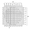
以下、本発明の加熱装置の構成例について、図1及び図2を用いて説明する。図1は、本発明の加熱装置の構成例を示す正面断面図である。図2は、図1に示す第1のランプユニット10及び第2のランプユニット20の各ヒータ1の配列例を示す平面図である。
Hereinafter, the structural example of the heating apparatus of this invention is demonstrated using FIG.1 and FIG.2. FIG. 1 is a front sectional view showing a configuration example of a heating device of the present invention. FIG. 2 is a plan view showing an arrangement example of the
図1に示すように、加熱装置100は、第1のランプユニット10、第2のランプユニット20、反射板2、第1のランプ固定台(不図示)、第2のランプ固定台3、石英窓4を備えて構成され、第1のランプユニット10及び第2のランプユニット20から放射された光を直接或いは反射板2で反射させ固定台5に固定された被処理物6に対して照射し、被処理物6を加熱する。
As shown in FIG. 1, the
反射板2は、例えば無酸素銅からなる母材に金をコートしてなり、第2のランプユニット20の上方に配置され、第1のランプユニット10及び第2のランプユニット20から上方に向けて照射された光を被処理物6側へ反射する。反射板2は、断面が円の一部、楕円の一部、放物線の一部又は平板状の場合が多い。このような反射板2は、後述の冷却風供給ノズル81によって空冷されている。なお、反射板2は水冷されていても良い。
The
第1のランプ固定台は第1のランプユニット10の各ヒータ1(図2に示すヒータ1a、1b、1c、1d、1e、1f、1g、1h、1i、1j)を支持し、第2のランプ固定台3は第2のランプユニット20の各ヒータ1(図2に示すヒータ1k、1l、1m、1n、1o、1p、1q、1r、1s、1t)を支持している。固定台5は、石英、シリコン(Si)、シリコンカーバイド(SiC)等により構成されることが好ましい。
The first lamp fixing base supports each heater 1 (
さらに、加熱装置100は、電源部7に繋がる電源供給ポート71、冷却ユニット8に繋がる冷却風供給ノズル81、温度計9に繋がる温度測定部91を備えている。温度計9は、電源部7に繋がる温度制御部92を備えている。
Furthermore, the
加熱装置100の内部は、冷却風ユニット8から供給され冷却風供給ノズル81から導入された冷却風が被処理物6を冷却することを防止するため、石英窓4によってランプユニット収納空間S1及び処理空間S2に仕切られている。このランプユニット収納空間S1には、冷却風供給ノズル81から冷却風が導入され、ランプユニット10及びランプユニット20における各ヒータ1に冷却風を吹き付けることにより各ヒータ1を構成する発光管(例えば、後述する発光管11)を冷却する。冷却風供給ノズル81の吹出し口82は、後述する各ヒータ1の封止部に対向して配置され、各ヒータ1の封止部を優先的に冷却する。これは、ヒータの封止部は他の箇所に比して耐熱性が低いことによる。
In order to prevent cooling air supplied from the cooling
一組の電源供給ポート71は、第1のランプユニット10及び第2のランプユニット20を固定する第1のランプ固定台及び第2のランプ固定台3に電気的に接続されている。第1のランプ固定台は第1のランプユニット10における各ヒータの給電装置(例えば、後述する外部リード18a〜18f等)と電気的に接続されている。また、第2のランプ固定台3は第2のランプユニット20における各ヒータの給電装置(例えば、後述する外部リード18a〜18f等)と電気的に接続されている。このような構成により、第1のランプユニット10及び第2のランプユニット20における各ヒータ1に電源部7から給電がなされる。図1では、1組の電源供給ポートが示されているが、ヒータの個数、後述するヒータ内のフィラメントの分割数や、複数のヒータの電気回路的な分割のさせ方等に応じて、一組の電源供給ポートの個数は決められる。
The set of
被処理物6の寸法に応じた個数の温度測定部91は、熱電対や光ファイバが使用され、被処理物6に当接或いは近接して各々配置されている。温度計9は、被処理物6からの熱エネルギーに応じた情報が温度測定部91から送信され、この情報に応じた電気信号を温度制御部92に送信する。温度制御部92は、被処理物の種類に応じて目標温度が設定され、被処理物6の温度が当該目標温度に一致するように電源部7から各ヒータ1に供給される給電量を調整する。
Thermocouples and optical fibers are used for the number of
加熱装置の加熱源を構成する複数のヒータは、上記したように、例えば、光透過性材料からなる発光管の内部にフィラメントが配設されてなる白熱ランプ構造を採用したものである。
そして、上記加熱源は、発光管の軸方向に少なくとも1つ以上のフィラメントが並ぶように構成されるヒータが、複数並列に配置されたランプユニットを複数有する。
As described above, the plurality of heaters constituting the heating source of the heating device adopts an incandescent lamp structure in which a filament is disposed inside an arc tube made of a light transmissive material.
The heating source includes a plurality of lamp units in which a plurality of heaters configured such that at least one filament is arranged in the axial direction of the arc tube are arranged in parallel.
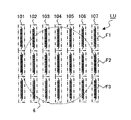
図3は、ランプユニットの概念図である。ランプユニットLUは、例えば、複数のヒータ101,102,103,104,105,106,107から構成される。各ヒータ101,102,103,104,105,106,107は、例えば、それぞれ複数のフィラメントF1,F2、F3を有する。
上記複数のフィラメントF1,F2、F3は、それぞれ独立に給電可能な構成となっている。図3の場合は、21個のフィラメントが、それぞれ独立に点灯可能となっている。
FIG. 3 is a conceptual diagram of the lamp unit. The lamp unit LU is composed of a plurality of
The plurality of filaments F1, F2, and F3 are configured to be able to supply power independently. In the case of FIG. 3, 21 filaments can be lit independently.
なお、当然ながら、各ヒータの個数、各ヒータがそれぞれ有するフィラメントの個数は、上記した例に限られるわけではなく、任意に設定することが可能である。 Of course, the number of heaters and the number of filaments each heater has are not limited to the above-described example, and can be arbitrarily set.
すなわち、ランプユニットLUの各ヒータにおけるフィラメントF1,F2,F3は、それぞれ個別の給電装置に接続されている。図4は、ヒータ101の各フィラメントと電源部との接続例を説明する概念図である。
図4に示すように、ヒータ101のフィラメントF1は給電装置PS1に接続されている。同様に、フィラメントF2は給電装置PS2に、フィラメントF3は給電装置PS3に接続されている。給電装置PS1、PS2、PS3は、図1に示す電源部7に相当する。主制御部MCは、給電装置PS1、PS2、PS3の動作を制御することにより、ヒータ101のフィラメントF1,F2,F3への給電を個別に制御することが可能である。
That is, the filaments F1, F2, and F3 in each heater of the lamp unit LU are connected to individual power supply devices. FIG. 4 is a conceptual diagram illustrating an example of connection between each filament of the
As shown in FIG. 4, the filament F1 of the
このようにランプユニットLUを構成することにより、ランプユニットLUから所定の距離だけ離間した被処理物上の照度分布を精密、かつ、任意の分布に設定することが可能となる。
よって、被処理物上の照度分布を被処理物形状に対して非対称に設定することが可能となる。そのため、被処理物である熱処理される基板上における場所的な温度変化の度合いの分布が基板形状に対し非対称である場合においても、それに対応して、被処理物上の照度分布を設定することが可能となり、被処理物を均一に加熱することが可能となる。
By configuring the lamp unit LU in this way, the illuminance distribution on the object to be processed that is separated from the lamp unit LU by a predetermined distance can be set precisely and arbitrarily.
Therefore, it is possible to set the illuminance distribution on the workpiece to be asymmetric with respect to the workpiece shape. Therefore, even when the distribution of the degree of local temperature change on the substrate to be processed which is to be processed is asymmetric with respect to the substrate shape, the illuminance distribution on the processing target should be set accordingly. It becomes possible to heat the object to be processed uniformly.
なお、被処理物6の比較的中央部において、隣り合うヒータの有するフィラメントであって、比較的近接して配置される複数のフィラメントから放射される光の強度分布がほぼ等しくなるように設定してもよい場合は、これらの複数のフィラメントへの電力供給は、同一の給電装置を用いて行っても良い。
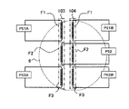
例えば、図5に示すように、被処理物6の比較的中央部において、隣り合うヒータ103,104の各フィラメントF2,F2から放射される光の強度分布がほぼ等しくなるように設定してもよい場合は、ヒータ103のフィラメントF1、F3、ヒータ104のフィラメントF1、F3への給電をそれぞれ独立の給電装置PS1A、PS3A,PS1B,PS3Bで行い、ヒータ103,104の各フィラメントF2,F2への給電は同一の給電装置PS2で行っても良い。
Note that the intensity distribution of light emitted from a plurality of filaments that are adjacent to the filaments of the adjacent heater and relatively close to each other is set to be approximately equal at the relatively central portion of the
For example, as shown in FIG. 5, the intensity distribution of the light emitted from the filaments F2 and F2 of the
また、被処理物6の比較的中央部において、各ヒータの隣り合うフィラメントから放射される光の強度分布がほぼ等しくなるように設定してもよい場合は、これらの隣り合うフィラメントへの電力供給は、同一の給電装置を用いて行っても良い。
例えば、図6に示すように、被処理物6の比較的中央部において、ヒータ103の隣り合うフィラメントF2,F3から放射される光の強度分布がほぼ等しくなるように設定してもよい場合、また、ヒータ104の隣り合うフィラメントF2,F3から放射される光の強度分布がほぼ等しくなるように設定してもよい場合は、ヒータ103のフィラメントF1、F4、ヒータ104のフィラメントF1、F4への給電をそれぞれ独立の給電装置PS1A、PS3A,PS1B,PS3Bで行い、ヒータ103の隣り合うフィラメントF2,F3への給電は同一の給電装置PS2Aで行い、ヒータ104の隣り合うフィラメントF2,F3への給電は同一の給電装置PS2Bで行っても良い。
In the case where the intensity distribution of the light emitted from the adjacent filaments of the heaters may be set to be substantially equal at the relatively central portion of the
For example, as shown in FIG. 6, when the intensity distribution of light emitted from the adjacent filaments F <b> 2 and F <b> 3 of the
すなわち、ランプユニットを構成するヒータの本数をn、各ヒータが有する分割されたフィラメントの個数をmとするとき、ランプユニットが備えるn×m個のフィラメントの少なくとも2つが共通の給電装置により給電されるようにしてもよい。
また、ランプユニットが2組ある場合、第1のランプユニットを構成するヒータの本数をn1、各ヒータが有する分割されたフィラメントの個数をm1とし、第2のランプユニットを構成するヒータの本数をn2、各ヒータが有する分割されたフィラメントの個数をm2とするとき、第1のランプユニットおよび第2のランプユニットが備えるn1×m1+n2×m2個のフィラメントの少なくとも2つが共通の給電装置により給電されるようにしてもよい。
That is, when the number of heaters constituting the lamp unit is n and the number of divided filaments of each heater is m, at least two of the n × m filaments included in the lamp unit are fed by a common feeding device. You may make it do.
When there are two lamp units, the number of heaters constituting the first lamp unit is n1, the number of divided filaments of each heater is m1, and the number of heaters constituting the second lamp unit is n2, where m2 is the number of divided filaments that each heater has, at least two of the n1 × m1 + n2 × m2 filaments included in the first lamp unit and the second lamp unit are fed by a common feeding device You may make it do.
まとめると、ランプユニットLUに含まれる全てのフィラメント各々に個別に給電装置を設けるのではなく、所望の照度分布によっては、複数のフィラメントを1台の給電装置に接続するようにしてもよい。言い換えれば、複数のヒータの電気回路的な分割のさせ方は、所望の照度分布に応じて任意に設定してよい。
なお、前記図4ないし図6においては、ヒータ101、103、104の各フィラメントF1,F2,F3,F4の両端と給電装置PS1、PS1A、PS1B、PS2、PS2A、PS2B、PS3、PS3A、PS3Bとを接続する各給電線は、ヒータ101、103、104の両端部以外から引き出されているように示されている。これは、フィラメントと給電装置との接続様態の理解を容易にするため概念的に示したものであり、実際は、後述する図7ないし図10に示すように、上記各給電線は全てヒータ101、103、104の両端部から引き出される。
例えば、後述する図7においては、フィラメント14aと給電装置19aとを接続する給電線は、給電線15a、15dがヒータ1の両端にそれぞれ設けられた封止部12a、12bから外部に突出する外部リード18a、18dと金属箔13a、13dを介して接続される構造を取ることにより、ヒータ1の両端から引き出されている。同様に、フィラメント14bと給電装置19bとを接続する給電線は、給電線15b、15cが封止部12a、12bから外部に突出する外部リード18b、18cと金属箔13b、13cを介して接続される構造を取ることにより、ヒータ1の両端から引き出されている。
In summary, a plurality of filaments may be connected to one power supply device depending on a desired illuminance distribution, instead of individually providing a power supply device for each filament included in the lamp unit LU. In other words, how to divide the plurality of heaters in an electric circuit may be arbitrarily set according to a desired illuminance distribution.
4 to 6, both ends of the filaments F1, F2, F3, and F4 of the
For example, in FIG. 7, which will be described later, the power supply line connecting the
上記した加熱装置100が備える第1のランプユニット10、第2のランプユニット20は、ランプユニットLUの概念を踏襲しており、各ヒータ1は、発光管の軸方向に少なくとも1つ以上のフィラメントが並ぶように構成されている。
The
図1、2に示すように、第1のランプユニット10は、被処理物6の上方において、紙面に垂直方向に10個のヒータ1(1a,1b,・・・・・1j)が並列配置されてなり、第2のランプユニット20は、被処理物6の上方においてランプユニット10の上方に接触乃至離間して配置され、紙面に平行に10個のヒータ1(1k,1l,・・・・・1t)が並列配置されてなる。
そして、各ヒータ1は、被処理物外の領域に無駄な光が照射されることを極力低減すべく、その発光領域(後述のフィラメントの全長)が、被処理物において各フィラメントが横切る領域の長さに少なくとも対応しているように構成してもよい。「少なくとも対応している」とは、各フィラメントの全長が、被処理物においてフィラメントが横切る領域の長さと同一である場合のみならず、被処理物において各フィラメントが横切る領域の長さを若干超えている場合も意味するものとする。
As shown in FIGS. 1 and 2, the
Each
ここで、発光領域が、被処理物において各フィラメントが横切る領域の長さに少なくとも対応するように設定する場合、各ヒータ1(1a,1b,・・・・・1j)、(1k,1l,・・・・・1t)におけるフィラメントの個数を調整してもよい。例えば、図2において、ヒータ1a、1jにおけるフィラメントの個数を1、ヒータ1b、1iにおけるフィラメントの個数を2、ヒータ1c、1hにおけるフィラメントの個数を3といったように調整してもよい。
Here, when the light emitting region is set so as to correspond at least to the length of the region traversed by each filament in the workpiece, each heater 1 (1a, 1b,... 1j), (1k, 11, ... The number of filaments in 1t) may be adjusted. For example, in FIG. 2, the number of filaments in the
あるいは、各ヒータ1(1a,1b,・・・・・1j)、(1k,1l,・・・・・1t)におけるフィラメントの個数は同数で、1個あたりのフィラメントの長さを各ヒータ1(1a,1b,・・・・・1j)、(1k,1l,・・・・・1t)で相違するようにしてもよい。例えば、ヒータ1bの各フィラメントF1,F2,F3の長さを、ヒータ1aの各フィラメントF1,F2,F3の長さより長く構成し、ヒータ1cの各フィラメントF1,F2,F3の長さを、ヒータ1bの各フィラメントF1,F2,F3の長さより長く構成して、各フィラメントF1,F2,F3の全長が、被処理物においてフィラメント(F1,F2,F3)が横切る領域の長さに少なくとも対応するように設定してもよい。
Alternatively, the number of filaments in each heater 1 (1a, 1b,... 1j), (1k, 1l,... 1t) is the same, and the length of each filament is set to each
また、フィラメントの個数、長さ双方を考慮してもよい。 Moreover, you may consider both the number of filaments and length.
なお、被処理物6は、第1のランプユニット10と第2のランプユニット20の間に配置しても良い。
The
第1のランプユニット10、第2のランプユニット20の具体的構成例としては、例えば、特許文献2に記載されている第1のランプユニットの構成をそのまま採用することも可能である。しかしながら、上記したように、特許文献2に記載されている第1のランプユニットに用いられている水平部と一対の垂直部とから構成されているU字形状を有するランプは、個々のランプが無視できない程度の空間を介在して離間して配置されることとなるため、この空間の直下に対応する部分では照度が比較的急峻に変化(低下)する。
そのため、各ランプを個別に点灯したり、各ランプへの供給電力を個別に調整して、被処理物上の照度分布を任意に設定しようとしても、上記空間の影響により、被処理物上の照度分布設定が著しく制限され、実用上、問題となる可能性が大きい。さらに、U字形状を有するランプを使用すると、ランプの垂直部に対応するスペースが必要となるため、小スペース化の観点からは好ましくない。
そこで、発明者らは、上記した特許文献2に記載されている第1のランプユニットの構成から生じる実用上の不具合を回避するために、下記に示す新しい構造のヒータを考案した。
As specific configuration examples of the
For this reason, even if each lamp is turned on individually or the power supplied to each lamp is individually adjusted to set the illuminance distribution on the object to be processed, the above-mentioned space affects the object. The illuminance distribution setting is remarkably limited, which is likely to cause a problem in practical use. Furthermore, when a lamp having a U-shape is used, a space corresponding to the vertical portion of the lamp is required, which is not preferable from the viewpoint of reducing the space.
Therefore, the inventors have devised a heater having a new structure shown below in order to avoid a practical problem resulting from the configuration of the first lamp unit described in
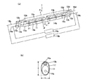
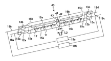
以下、本発明の第1の実施形態に係るヒータについて図7を用いて説明する。図7(a)は斜視図を示し、図7(b)は図7(a)に示すA−A´線にて切断した断面図を示す。 Hereinafter, the heater according to the first embodiment of the present invention will be described with reference to FIG. FIG. 7A is a perspective view, and FIG. 7B is a cross-sectional view taken along the line AA ′ shown in FIG.
図7に示すように、ヒータ1は、例えば石英ガラス等の光透過性材料からなり、その軸方向に直交する平面で切断した場合の断面が長円形状を有する発光管11を備える。「長円形状」とは、前記断面における長手方向の長さaが、長手方向に垂直な方向の長さbに比して大きい形状(例えば、楕円形状等)の全てを意味するものとする。なお、発光管11は、前記断面が円形状のものであっても良い。
発光管11は、一端側に金属箔13a,13bが埋設されピンチシールにより封止部12aが形成され、他端側に金属箔13c,13dが埋設されて一端側と同様にして封止部12bが形成され、発光管内部が気密に封止されている。発光管11の内部には、例えばタングステンからなり、発光管11の軸方向において2つに分割されたフィラメント14a,14bが、同一軸上に発光管11の軸に沿って空間L1を隔てて配設されている。
この空間L1は、フィラメント14a、14bが存在しない空間であって非発光領域であるため、空間L1の全長が大きすぎる場合、被処理物上での照射光の強度分布にバラツキが生じる。そのため空間L1の全長はできるだけ小さい方が望ましい。しかしながら、空間L1の全長が小さすぎる場合、長手方向において対向するフィラメント14aと14bとの間で不所望な放電が発生し易くなる。そのため空間L1の全長は、ある程度大きい必要がある。これらの知見を踏まえ、実験した結果、被処理物上における照射光の強度分布のバラツキを極力小さくすることができ、かつ、長手方向において対向するフィラメント14aと14bとの間で不所望な放電が発生することのないようにするには、空間L1の全長が2mm〜8mmの範囲に設定されることが好ましいことが判明した。空間L1の全長は2mm〜5mmの範囲に設定されることが特に好ましく、例えば5mmである。
As shown in FIG. 7, the
In the
Since the space L1 is a space where the
本発明のヒータは、上記2つに分割されたフィラメントがそれぞれ独立に給電されることが特徴であり、詳細には以下のとおりである。
フィラメント14aは、一端側に金属箔13aに接続された給電線15aが電気的に接続され、他端側に金属箔13dに接続された給電線15dが電気的に接続されている。詳細には、給電線15dは、フィラメント14bと対向する箇所の外側が、例えば石英ガラスからなる絶縁管16bで被覆され、フィラメント14aの他端側に接続されている。これにより、対向するフィラメント14bと給電線15dの間で不所望な放電が発生することを確実に防止することができる。
フィラメント14bは、フィラメント14aと同様にして、一端側に金属箔13cに接続された給電線15cが電気的に接続され、他端側に金属箔13bに接続された給電線15bが電気的に接続されている。給電線15bは、フィラメント14aと対向する箇所が、例えば石英ガラスからなる絶縁管16aで被覆され、フィラメント14bの他端側に接続されている。
The heater according to the present invention is characterized in that the two divided filaments are independently supplied with power, and the details are as follows.
One end of the
In the same manner as the
このようなフィラメント14a及び14bは、発光管11の軸方向に複数個配設された、発光管11の内壁と絶縁管16a或いは16bの間に挟持されたアンカー17によって支持されている。
A plurality of
さらに、封止部12a側の金属箔13a及び13bには、それぞれ封止部12aから外部に導出する外部リード18a及び18bが電気的に接続され、封止部12b側の金属箔13c及び13dにも同様にして、それぞれ外部リード18c及び18dが電気的に接続されている。これにより、フィラメント14aは外部リード18a及び18dに電気的に接続され、フィラメント14bは外部リード18b及び18cに電気的に接続されている。
Furthermore,
そして、上記構成のヒータ1は、外部リード18aと18dの間に第1の給電装置19aが接続され、外部リード18bと18cの間に第2の給電装置19bが接続され、フィラメント14a及び14bがそれぞれ別個の給電装置によって独立に給電されることにより、ヒータが点灯駆動する。給電装置19a及び19bは、可変電源であり、例えば後述のように、フィラメント14a直下の被処理物の温度が、フィラメント14bの直下の被処理物の温度よりも低いような場合においては、フィラメント14aへの給電を増加させることにより、フィラメント14aから放射される光量を増加させるよう調整することができる。
In the
上記した第1の給電装置19a、第2の給電装置19bは、図1に示した加熱装置における電源部7に対応する。ここで、ヒータ1(1a、・・・、1j、1k、・・・、1t)それぞれが図7に示すような構造であって、各フィラメント各々に給電装置が接続されている場合は、40個の給電装置が上記した電源部7に相当する。
なお、各給電装置は、フィラメントに対して、DC電力を供給するものでもよいし、AC電力を供給するものでもよい。
The first
Each power supply device may supply DC power or supply AC power to the filament.
以上のような本発明の第1の実施形態に係るヒータによれば、図7に示すように、フィラメント14aに電気的に繋がる一対の外部リード18a及び18dが発光管の両端に連続する封止部12a及び12bからそれぞれ外部に導出し、フィラメント14bに電気的に繋がる一対の外部リード18b及び18cが封止部12a及び12bからそれぞれ外部に導出していることにより、ヒータに高電圧を印加する場合に、一対の外部リードが同一の封止部に存在しないため、絶縁抵抗不良や漏電などの不具合が発生しにくい、などの効果がある。
According to the heater according to the first embodiment of the present invention as described above, as shown in FIG. 7, a pair of
ここで、第1の給電装置19a、第2の給電装置19bが、各フィラメント14a及び14bにDC電力を供給する場合を考える。第1の給電装置19aの高電圧側が外部リード18aに接続され、第2の給電装置19bの低電圧側が外部リード18bに接続された場合、外部リード18aと外部リード18bとの電位差が大きくなる。よって、場合によっては、封止部12aにおいて、絶縁抵抗不良や漏電などの不具合が発生する可能性も無いとは言えない。よって、同一の封止部に存在する各フィラメントの各外部リードへの給電は、各外部リード間の電位差が大きくならないように設定することが望ましい。
図7に示すヒータの場合、例えば、第1の給電装置19aの高電圧側を外部リード18aに接続するとともに、第2の給電装置19bの高電圧側を外部リード18bに接続するように構成する。
Here, consider a case where the first
In the case of the heater shown in FIG. 7, for example, the high voltage side of the first
一方、第1の給電装置19a、第2の給電装置19bが、各フィラメント14a及び14bにAC電力を供給する場合を考える。ここで、一対の外部リード18a及び18dに第1の給電装置19aから印加される電圧の電圧波形の位相と、一対の外部リード18b及び18cに第2の給電装置19bから印加される電圧の電圧波形の位相とにずれが生じた場合、ある時点においては、封止部12aにおける外部リード18aと外部リード18bとの電位差や封止部12bにおける外部リード18cと外部リード18dとの電位差が大きくなる。よって、場合によっては、封止部12aおよび12bにおいて、絶縁抵抗不良や漏電などの不具合が発生する可能性も無いとは言えない。
よって、外部リード18aと外部リード18bの双方、もしくは外部リード18cと外部リード18dの双方は接地されていることが望ましい。
On the other hand, consider a case where the first
Therefore, it is desirable that both the
また、給電線15b及び15dは、フィラメント14a及び14bに対向する箇所が絶縁管16a及び16bで被覆されているため、対向するフィラメント14a及び14bとの間で不所望な放電が生じることを確実に防止することができる。
In addition, since the
さらに、発光管がその軸方向に直交する平面で切断した場合の断面が長円形状を有することにより、図7に示す如く、フィラメント14a及び14bと、給電線15b及び15dを被覆する絶縁管16a及び16bとを、縦方向(図7(b)に示すa方向)において発光管の軸方向に沿って並列配置する、という構成を容易に実現することができる。
Further, since the cross section when the arc tube is cut by a plane orthogonal to the axial direction has an oval shape, as shown in FIG. 7, the insulating
そして、本発明の第1の実施形態に係るヒータを備えた加熱装置によれば、光透過性材料からなる発光管11の内部にフィラメント14が配設され、各分割されたフィラメント14a及び14bがそれぞれ独立に給電される、という構成のヒータ10を備えることにより、以下の効果を奏するものである。
And according to the heating apparatus provided with the heater which concerns on the 1st Embodiment of this invention, the filament 14 is arrange | positioned inside the arc_tube | light_emitting_tube 11 which consists of a light-transmitting material, and each divided
すなわち、図2に示す被処理物6のうち、例えばヒータ1bとヒータ1m乃至1oとが交差する箇所の直下の周辺領域(以下、領域1ともいう)の温度が、被処理物6における他の領域(以下、領域2ともいう)の温度に比して低いような場合、もしくは、領域1における温度上昇の度合いが領域2における温度上昇の度合いより小さいと予め判明しているような場合において、ヒータ1bの領域1に対応するフィラメントへの給電を増加させフィラメントからの発光光量を増加させることにより、領域1と領域2の間に温度分布が生じることを確実に防止し、被処理物6の全体にわたって均一な温度分布を実現することができる。
That is, among the objects to be processed 6 shown in FIG. 2, for example, the temperature of a peripheral region (hereinafter also referred to as region 1) immediately below a portion where the
しかも、1本の発光管11の内部に、発光管の軸方向に複数の分割されたフィラメントが、同一軸上に発光管の軸に沿って配置されてなる構成のヒータ1を複数並べて配置して加熱装置を構成することにより、個々のフィラメント14aと14bの間の空間L1の全長を、被処理物上における照射光の強度分布のバラツキを極力小さくすることができ、かつ、長手方向において対向するフィラメント14aと14bとの間で不所望な放電が発生することのない範囲、すなわち、2〜8mmの範囲であって、特に好ましくは2mm〜5mmの範囲と極めて小さくすることができるため、従来の装置に比して被処理物6の温度分布を均一にすることができるとともに、ヒータを配設するのに必要なスペース(主として高さ方向)が小さくなることにより、加熱装置を小型化することができる。
In addition, a plurality of
また、被処理物6が円形状を有する半導体ウェハであるとき、半導体ウエハ表面を、径方向の幅が略同一で、同心状の複数の円環状仮想領域に分割した場合を考える。なお、一番内側の領域は円形領域とする。この場合、半導体ウエハのエッジ部分を含む最も外側に位置する円環状仮想領域は、領域の外側の円の直径が、他の円環状仮想領域と比較して最大となる。よって、最も外側に位置する円環状仮想領域の面積は、他の円環状仮想領域と比較して最大となる。
一方、エッジ部分近傍は、端面からの放熱が発生し、また半導体ウエハを支持する固定台5と接触する部分でもあるため、他の中心に近い円環状仮想領域より、熱が逃げ易く、結果として温度分布が生じやすい。そのため、最も外側に位置する円環状仮想領域は、他の仮想領域と比較して、半導体チップが不良となりやすい。特に、上記したように最も外側に位置する円環状仮想領域は他の領域と比較して面積が最大であるため、不良となる半導体チップの数の多さを無視できない。
よって、本発明のヒータを有する加熱源を制御して、最も外側に位置する円環状仮想領域における温度分布が小さくなるように放射する光の強度分布を変えて設定し、温度変化が生じ易い箇所である半導体ウェハのエッジ部分の温度分布を均一にすることにより、多数の良質な半導体チップを供給することが可能となる。
Further, when the
On the other hand, the vicinity of the edge part generates heat from the end face, and is also a part in contact with the fixed
Therefore, by controlling the heating source having the heater according to the present invention, the intensity distribution of the emitted light is changed and set so that the temperature distribution in the outer annular virtual region is reduced, and the temperature is likely to change. By making the temperature distribution of the edge portion of the semiconductor wafer uniform, a large number of high-quality semiconductor chips can be supplied.
被処理物において各ヒータ1の各フィラメントが横切る領域と各フィラメントの全長が同一であると、上記各フィラメントが横切る領域の端部は、フィラメントと給電線との境界部分に相当する。給電線は発光しないので、当該領域への光照射には、ヒータの発光している部分と発光していない部分とが関係する。一方、当該領域以外の光照射は、ヒータの発光部分のみが関係する。結果として、当該領域に照射される光量は、当該端部以外の領域に照射される光量と比較して小さくなり、被処理物のエッジ部分の温度が上記領域の他の箇所に比して低下することにより温度分布が生じる可能性がある。
一方、各フィラメントの全長が当該領域を大幅に上回っているとヒータに余分なエネルギーが投入されるので、光エネルギーの利用効率が低くなる。
ここで、各ヒータ1において、そのフィラメントの全長を、被処理物において各フィラメントが横切る領域の長さに少なくとも対応させ、特に、各フィラメントの全長が被処理物において各フィラメントが横切る領域の長さを若干超えているように設定することにより、放射される光強度が小さいフィラメントの端部を被処理物のエッジ部分から遠ざけることが可能となり、また、被処理物外の領域に無駄な光が照射されることを極力低減することができる。よって、上記したような問題を生じる心配がない。
In the object to be processed, when the region traversed by each filament of each
On the other hand, if the total length of each filament is significantly greater than the region, excess energy is input to the heater, so that the light energy utilization efficiency is lowered.
Here, in each
次に、本発明の第2の実施形態に係るヒータについて、以下に図8を用いて説明する。図8は、本発明の第2の実施形態に係るヒータを示す斜視図である。なお、図8において、図7と同一乃至相当する部分については同一符号で示す。 Next, a heater according to a second embodiment of the present invention will be described below with reference to FIG. FIG. 8 is a perspective view showing a heater according to the second embodiment of the present invention. In FIG. 8, parts that are the same as or correspond to those in FIG.
図8に示すように、第2の実施形態に係るヒータ40は、軸方向において分割された2つのフィラメント14aと14bが、同一軸上に発光管11の軸に沿って配設されている。フィラメント14aと14bの間には、例えば石英ガラスからなる絶縁体41が、フィラメント14a及び14bとの間に空間が存在するよう介設されている。なお、絶縁体41とフィラメント14a及び14bとは当接していても良い。給電線15dは、絶縁体41に設けられた貫通孔42を通過するとともに、フィラメント14bと対向する箇所の外側が絶縁管16bで被覆され、一端側が金属箔13dに電気的に接続され、他端側がフィラメント14aに電気的に接続されている。給電線15bは、絶縁体41に設けられた貫通孔43を通過するとともに、フィラメント14aと対向する箇所の外側が絶縁管16aで被覆され、一端側が金属箔13bに電気的に接続され、他端側がフィラメント14bに電気的に接続されている。
As shown in FIG. 8, in the
絶縁体41の軸方向における厚みL2は、フィラメント14aと14bの間で不所望な放電が生じることのないよう1mm〜3mmの範囲であって、例えば2mmである。絶縁体41とフィラメント14a及び/または14bとの間に空間が介在する場合は、被処理物上における照射光の強度分布のバラツキを極力小さくすることができ、かつ、長手方向において対向するフィラメント14aと14bとの間で不所望な放電が発生することのないよう、フィラメント14aと14bとの離間距離L3は、3mm〜8mmの範囲であることが好ましく、特に3mm〜5mmの範囲であることが好ましく、例えば5mmである。
A thickness L2 of the insulator 41 in the axial direction is in a range of 1 mm to 3 mm so as not to cause an undesired discharge between the
このような第2の実施形態に係るヒータ40によっても、第1の実施形態に係るヒータと同様の効果を奏する。すなわち、ヒータ40を備えた加熱装置において、被処理物6の全体にわたって均一な温度分布を実現する、小型化できる等の効果を奏することができる。
しかも、フィラメント14a及び14bの間に絶縁体41が介設されていることにより、フィラメント14aと14bの間で不所望な放電が生じることを確実に防止することができる。さらに、フィラメント14a及び14bに繋がる給電線15d及び15bが、絶縁体41に設けられた貫通孔42及び貫通孔43を通過していることにより、給電線15dと15bとが絶縁体41によって仕切られるため、両給電線が接触して短絡することを確実に防止することができる。
The
In addition, since the insulator 41 is interposed between the
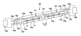
さらに、本発明の第3の実施形態に係るヒータについて、以下に図9を用いて説明する。図9は、本発明の第3の実施形態に係るヒータを示す斜視図である。なお、図9において、図7と同一乃至相当する部分については同一符号で示す。 Furthermore, a heater according to a third embodiment of the present invention will be described below with reference to FIG. FIG. 9 is a perspective view showing a heater according to the third embodiment of the present invention. In FIG. 9, parts that are the same as or correspond to those in FIG.
図9に示すように、ヒータ50は、発光管11の内部に、2つのフィラメント組立体51及び52が絶縁体53を介在して対向して配設され、発光管11の軸方向において分割された2つのフィラメント14aと14bが、同一軸上に発光管11の軸に沿って配設されている。絶縁体53は、フィラメント14a及び14bとの間に空間が介在するよう配設されている。フィラメント14aと14bとの離間距離L4は、被処理物上における照射光の強度分布のバラツキを極力小さくすることができ、かつ、長手方向において対向するフィラメント14aと14bとの間で不所望な放電が発生することのないよう、3mm〜8mmの範囲であることが好ましく、特に3mm〜5mmの範囲であることが好ましく、例えば5mmである。
As shown in FIG. 9, the
フィラメント組立体51は、フィラメント14a、給電線15a、給電線15b、絶縁管16aから構成され、該組立体における給電線15bが、フィラメント14aに接続される側の端部がコ字状に折り曲げられて形成され、フィラメント14aと対向する箇所である、コ字状部分に繋がる直線部分が絶縁管16aで被覆されている。
フィラメント組立体52は、フィラメント14b、給電線15c、給電線15d、絶縁管16bから構成され、該組立体における給電線15dが、フィラメント14bに接続される側の端部がコ字状に折り曲げられて形成され、フィラメント14bと対向する箇所である、コ字状部分に繋がる直線部分が絶縁管16bで被覆されている。
フィラメント14aに電気的に繋がる外部リード18a及び18bが封止部12aからそれぞれ外部に導出し、フィラメント14bに電気的に繋がる外部リード18c及び18dが封止部12bからそれぞれ外部に導出している。
The
The
External leads 18a and 18b that are electrically connected to the
そして、図9に示すように、ヒータ50は、外部リード18aと18bの間に給電装置19aが電気的に接続され、さらに、外部リード18cと18dの間に給電装置19bが電気的に接続され、フィラメント14a及び14bへの給電をそれぞれ別個の給電装置によって独立に行なう構成である。
As shown in FIG. 9, in the
このような第3の実施形態に係るヒータ50によっても、第1の実施形態に係るヒータと同様の効果を奏する。すなわち、ヒータ50を備えた加熱装置において、被処理物6の全体にわたって均一な温度分布を実現する、小型化できる等の効果を奏することができる。
しかも、ヒータ50によれば、フィラメント14aに対し封止部12a側の外部リード18a及び18bによって給電し、フィラメント14bに対し封止部12b側の外部リード18c及び18dによって給電していることから、フィラメント14aと14bの間に介設された絶縁体53には給電線を通過させるための貫通孔を設けずとも両給電線が短絡するおそれがないため、ヒータ作製に要するコストを低減することができる。
The
Moreover, according to the
なお、ヒータ50においては、フィラメント14aに電気的に繋がる一対の外部リード18a及び18bが同一の封止部12aからそれぞれ外部に導出し、フィラメント14bに電気的に繋がる一対の外部リード18c及び18dが同一の封止部12bからそれぞれ外部に導出している。よって、ヒータに高電圧を印加する場合、絶縁構造、漏電対策等を考慮する必要がある。
In the
さらに、本発明の第4の実施形態に係るヒータについて、以下に図10を用いて説明する。図10は、本発明の第4の実施形態に係るヒータを示す正面図である。なお、図10において、図7と同一乃至相当する部分については同一符号で示す。 Furthermore, a heater according to a fourth embodiment of the present invention will be described below with reference to FIG. FIG. 10 is a front view showing a heater according to the fourth embodiment of the present invention. 10, parts that are the same as or correspond to those in FIG. 7 are denoted by the same reference numerals.
図10に示すように、ヒータ60の発光管11は、一端側に金属箔13a、13b及び13cが埋設されピンチシールされることにより封止部12aが形成され、他端側に金属箔13d、13e、13fが埋設されピンチシールされることにより封止部12bが形成され、発光管内部が気密に封止されている。このような発光管11の内部には、軸方向において3つに分割されたフィラメント14a,14b,14cが、同一軸上に発光管11の軸に沿って配設されている。フィラメント14aと14bとの間には絶縁体61aが介設され、フィラメント14bと14cとの間には絶縁体61bが介設されている。さらに、金属箔13a、13b、13c、13d、13e、及び13fには、それぞれ、外部リード18a、18b、18c、18d、18e、及び18fが電気的に接続されている。
As shown in FIG. 10, the
フィラメント14aは、一端側に金属箔13aに接続された給電線15aが電気的に接続され、他端側に金属箔13fに接続された給電線15fが電気的に接続されている。詳細には、給電線15fは、絶縁体61aに設けられた貫通孔611a、フィラメント14bと対向する絶縁管16c、絶縁体61bに設けられた貫通孔611b、及びフィラメント14cと対向する絶縁管16fを通過し、金属箔13fに接続される。
フィラメント14bは、一端側に、絶縁体61aに設けられた貫通孔612a、及びフィラメント14aと対向する絶縁管16aを通過するとともに、金属箔13bに接続された給電線15bが電気的に接続されている。フィラメント14bの他端側には、絶縁体61bに設けられた貫通孔612b、及びフィラメント14cと対向する絶縁管16eを通過するとともに、金属箔13eに接続された給電線15eが電気的に接続されている。
フィラメント14cは、一端側に金属箔13cに接続された給電線15cが電気的に接続され、他端側に金属箔13dに接続された給電線15dが電気的に接続されている。詳細には、給電線15cは、絶縁体61bに設けられた貫通孔613b、フィラメント14bと対向する絶縁管16d、絶縁体61aに設けられた貫通孔613a、及びフィラメント14aと対向する絶縁管16bを通過し、金属箔13cに接続されている。
One end of the
One end of the
One end of the filament 14c is electrically connected to a
ヒータ60は、外部リード18aと18fの間に第1の給電装置62が接続され、外部リード18bと18eの間に第2の給電装置63が接続され、外部リード18cと18dの間に第3の給電装置64が接続されている。すなわち、フィラメント14a、14b、及び14cは、それぞれ別個の給電装置によって独立に給電されることにより、ヒータが点灯駆動する。給電装置62、63、及び64は、可変電源であり、必要に応じて給電量を調整することができる。
The heater 60 has a first
ここで、上記した給電装置62、63、64は、図1に示した加熱装置における電源部7に対応する。ここで、ヒータ1(1a、・・・、1j、1k、・・・、1t)それぞれが図10に示すような構造であって、各フィラメント各々に給電装置が接続されている場合は、60個の給電装置が上記した電源部7に相当する。
なお、各給電装置は、フィラメントに対して、DC電力を供給するものでもよいし、AC電力を供給するものでもよい。
Here, the above-described
Each power supply device may supply DC power or supply AC power to the filament.
このような第4の実施形態に係るヒータによれば、軸方向において3つに分割されたフィラメント14a、14b、及び14cが、同一軸上に発光管11の軸に沿って配設されているとともに、それぞれのフィラメントへの給電量を別個の給電装置によって調整することができるため、それぞれのフィラメントから放射される光量を自在に調整することができる。これにより、上記実施形態1乃至3に係るヒータに比して、さらに狭小な領域における温度を調整することができるため、被処理物6の温度分布の均一性をさらに向上させることができる、という効果を奏する。
さらに、第1乃至第3の実施形態に係るヒータと同様に、加熱装置を小型化することができる等の効果を奏する。
According to the heater according to the fourth embodiment as described above, the
Further, as with the heaters according to the first to third embodiments, the heating device can be reduced in size and the like.
以下、本発明に係るヒータを備えた加熱装置の数値例を示す。本発明は、以下に示す数値例に限定されるものではない。
発光管(11)は、石英ガラスからなり、発光管の軸に直交する平面を含む断面において、図7(b)に示すaが11mmであり、同図に示すbが8mmである。また、発光管(11)は、肉厚が1mmであり、全長(両封止部(12)を加えた長さ)が447mmの直管状のものである。
フィラメント(14)は、線径0.53mmのタングステン線を0.66mmのピッチで巻き回すことにより、外径3.86mmのコイル状に構成され、フィラメント14a及び14bの全長がそれぞれ200mmである。
絶縁管(16)は、石英ガラスからなり、外径が2mm、内径が1mm、全長が205mmの直管状のものである。
Hereinafter, numerical examples of a heating device including the heater according to the present invention will be shown. The present invention is not limited to the numerical examples shown below.
The arc tube (11) is made of quartz glass, and in a cross section including a plane orthogonal to the axis of the arc tube, a shown in FIG. 7B is 11 mm, and b shown in FIG. 7 is 8 mm. The arc tube (11) is a straight tube having a thickness of 1 mm and a total length (length including both sealing portions (12)) of 447 mm.
The filament (14) is formed in a coil shape with an outer diameter of 3.86 mm by winding a tungsten wire with a wire diameter of 0.53 mm at a pitch of 0.66 mm, and the total length of the
The insulating tube (16) is made of quartz glass and is a straight tube having an outer diameter of 2 mm, an inner diameter of 1 mm, and a total length of 205 mm.
なお、上記第1乃至第4の実施形態のヒータによれば、分割された各フィラメントが同一軸上に配設された形態が示されているが、本発明はこれに限定されるものではない。すなわち、本発明は、分割された各フィラメントが同一軸上に配設されていない構成を採用しても良い。 In addition, according to the heater of the said 1st thru | or 4th Embodiment, although each divided | segmented filament was shown on the same axis | shaft, the form is shown, This invention is not limited to this. . That is, the present invention may adopt a configuration in which the divided filaments are not arranged on the same axis.
1 ヒータ
2 反射板
3 ランプ固定台
4 石英窓
5 固定台
6 被処理物
7 電源部
71 電源供給ポート
8 冷却風ユニット
81 冷却風供給ノズル
82 吹出し口
9 温度計
91 温度測定部
92 温度制御部
10 第1のランプユニット
11 発光管
12 封止部
13 金属箔
14 フィラメント
15 給電線
16 絶縁管
17 アンカー
18 外部リード
19 給電装置
20 第2のランプユニット
40 ヒータ
41 絶縁体
42 貫通孔
43 貫通孔
50 ヒータ
51 フィラメント組立体
52 フィラメント組立体
53 絶縁体
60 ヒータ
61 絶縁体
62 給電装置
63 給電装置
64 給電装置
611 貫通孔
612 貫通孔
613 貫通孔
100 加熱装置
MC 主制御部
LU ランプユニット
F1 フィラメント
F2 フィラメント
F3 フィラメント
F4 フィラメント
PS1 給電装置
PS2 給電装置
PS3 給電装置
PS1A 給電装置
PS2A 給電装置
PS3A 給電装置
PS1B 給電装置
PS2B 給電装置
PS3B 給電装置
DESCRIPTION OF
Claims (14)
前記フィラメントは、軸方向で複数に分割され、各分割されたフィラメントが、それぞれ独立に給電されることを特徴とするヒータ。 In a heater in which a filament is disposed inside one arc tube made of a light transmissive material,
The filament is divided into a plurality of pieces in the axial direction, and each divided filament is supplied with power independently.
上記ランプユニットは上記ヒータが複数本並列配置してなることを特徴とする加熱装置。 A heating device that has a lamp unit comprising the heater according to claim 1 and irradiates the object to be processed with light emitted from the lamp unit.
The lamp unit comprises a plurality of the heaters arranged in parallel.
上記第1のランプユニットと上記第2ランプユニットとは互いに対向する位置に配置されていて、
上記第1のランプユニットを構成する各ヒータの軸方向と上記第2のランプユニットを構成する各ヒータの軸方向とは互いに交差していることを特徴とする加熱装置。 A first lamp unit in which a plurality of heaters according to claim 1 are arranged in parallel, and a second lamp unit in which a plurality of heaters according to claim 1 are arranged in parallel. , A heating device for heating the object to be processed by irradiating the object to be processed with light emitted from the first lamp unit and the second lamp unit,
The first lamp unit and the second lamp unit are arranged at positions facing each other,
A heating apparatus, wherein an axial direction of each heater constituting the first lamp unit and an axial direction of each heater constituting the second lamp unit intersect each other.
The heating apparatus according to claim 9, wherein the total length of the filament is changed for each heater so as to fit the workpiece.
Priority Applications (7)
| Application Number | Priority Date | Filing Date | Title |
|---|---|---|---|
| JP2005191222A JP2006279008A (en) | 2005-03-02 | 2005-06-30 | Heater and heating apparatus having the same |
| TW095100084A TW200633166A (en) | 2005-03-02 | 2006-01-02 | Heater and heating device with heaters |
| KR1020060009885A KR100859401B1 (en) | 2005-03-02 | 2006-02-02 | Heater and heating device having the heater |
| EP06003999A EP1699071B1 (en) | 2005-03-02 | 2006-02-28 | Heater and heating device with heaters |
| DE602006007049T DE602006007049D1 (en) | 2005-03-02 | 2006-02-28 | Heating element and heating device with heating elements |
| US11/362,788 US7656079B2 (en) | 2005-03-02 | 2006-02-28 | Heater and heating device with heaters with lamps having an independently powered multiple part filament |
| CN2008100996426A CN101295632B (en) | 2005-03-02 | 2006-03-02 | Heating device |
Applications Claiming Priority (2)
| Application Number | Priority Date | Filing Date | Title |
|---|---|---|---|
| JP2005057803 | 2005-03-02 | ||
| JP2005191222A JP2006279008A (en) | 2005-03-02 | 2005-06-30 | Heater and heating apparatus having the same |
Related Child Applications (2)
| Application Number | Title | Priority Date | Filing Date |
|---|---|---|---|
| JP2010285312A Division JP2011103475A (en) | 2005-03-02 | 2010-12-22 | Heater lamp |
| JP2010285313A Division JP2011103476A (en) | 2005-03-02 | 2010-12-22 | Heating device with heater lamp |
Publications (2)
| Publication Number | Publication Date |
|---|---|
| JP2006279008A true JP2006279008A (en) | 2006-10-12 |
| JP2006279008A5 JP2006279008A5 (en) | 2007-06-28 |
Family
ID=36481395
Family Applications (1)
| Application Number | Title | Priority Date | Filing Date |
|---|---|---|---|
| JP2005191222A Pending JP2006279008A (en) | 2005-03-02 | 2005-06-30 | Heater and heating apparatus having the same |
Country Status (6)
| Country | Link |
|---|---|
| US (1) | US7656079B2 (en) |
| EP (1) | EP1699071B1 (en) |
| JP (1) | JP2006279008A (en) |
| KR (1) | KR100859401B1 (en) |
| DE (1) | DE602006007049D1 (en) |
| TW (1) | TW200633166A (en) |
Cited By (23)
| Publication number | Priority date | Publication date | Assignee | Title |
|---|---|---|---|---|
| JP2008135313A (en) * | 2006-11-29 | 2008-06-12 | Matsushita Electric Ind Co Ltd | Heating element unit and heating device |
| JP2008166073A (en) * | 2006-12-27 | 2008-07-17 | Ushio Inc | Filament lamp and light irradiation heating device |
| EP1962323A1 (en) | 2007-02-26 | 2008-08-27 | Ushiodenki Kabushiki Kaisha | Filament lamp and light irradiation type heat treatment apparatus |
| EP1998358A2 (en) | 2007-05-29 | 2008-12-03 | Ushiodenki Kabushiki Kaisha | Filament lamp and light-irradiation-type heat treatment device |
| JP2008300073A (en) * | 2007-05-29 | 2008-12-11 | Ushio Inc | Filament lamp |
| EP2003677A2 (en) | 2007-05-29 | 2008-12-17 | Ushiodenki Kabushiki Kaisha | Filament lamp and light irradiation type heat treatment device |
| WO2009008673A2 (en) * | 2007-07-10 | 2009-01-15 | Jusung Engineering Co., Ltd. | Substrate heating apparatus |
| JP2009009927A (en) * | 2007-05-29 | 2009-01-15 | Ushio Inc | Filament lamp and light irradiation type heat-treatment device |
| JP2009093941A (en) * | 2007-10-10 | 2009-04-30 | Ushio Inc | Filament lamp, and light-irradiating type heating treatment device |
| EP2059089A2 (en) | 2007-11-06 | 2009-05-13 | Ushiodenki Kabushiki Kaisha | Light irradiation type heat treatment device |
| EP2058839A2 (en) | 2007-11-08 | 2009-05-13 | Ushiodenki Kabushiki Kaisha | Filament lamp and light irradiation type heat treatment device |
| JP2009200401A (en) * | 2008-02-25 | 2009-09-03 | Ushio Inc | Light irradiation type heating method and light irradiation type heating apparatus |
| EP2105948A2 (en) | 2008-03-27 | 2009-09-30 | Ushiodenki Kabushiki Kaisha | Filament lamp |
| EP2107596A2 (en) | 2008-03-31 | 2009-10-07 | Ushiodenki Kabushiki Kaisha | Filament lamp |
| JP2010033857A (en) * | 2008-07-29 | 2010-02-12 | Ushio Inc | Filament lamp |
| EP2154707A2 (en) | 2008-07-28 | 2010-02-17 | Ushio Denki Kabushiki Kaisha | Filament lamp |
| JP2010040230A (en) * | 2008-08-01 | 2010-02-18 | Ushio Inc | Filament lamp |
| JP2010055763A (en) * | 2008-08-26 | 2010-03-11 | Ushio Inc | Filament lamp, and light irradiation type heating treatment device |
| EP2166561A1 (en) | 2008-09-22 | 2010-03-24 | Ushiodenki Kabushiki Kaisha | Filament lamp |
| EP2169705A2 (en) | 2008-09-26 | 2010-03-31 | Ushiodenki Kabushiki Kaisha | Filament lamp |
| JP2015216254A (en) * | 2014-05-12 | 2015-12-03 | 東京エレクトロン株式会社 | Heater feeding mechanism and temperature control method of stage |
| CN107526269A (en) * | 2016-06-20 | 2017-12-29 | 株式会社东芝 | Heater and heater |
| JP2019057613A (en) * | 2017-09-21 | 2019-04-11 | 株式会社Screenホールディングス | Heat treatment apparatus |
Families Citing this family (17)
| Publication number | Priority date | Publication date | Assignee | Title |
|---|---|---|---|---|
| JP4692249B2 (en) * | 2005-11-30 | 2011-06-01 | ウシオ電機株式会社 | Filament lamp |
| JP4893159B2 (en) | 2006-08-24 | 2012-03-07 | ウシオ電機株式会社 | Filament lamp and light irradiation type heat treatment equipment |
| ITMI20061648A1 (en) * | 2006-08-29 | 2008-02-29 | Star Progetti Tecnologie Applicate Spa | HEAT IRRADIATION DEVICE THROUGH INFRARED |
| KR100918103B1 (en) * | 2008-03-25 | 2009-09-22 | 강병호 | Heating pipe |
| KR101103180B1 (en) | 2008-03-27 | 2012-01-04 | 우시오덴키 가부시키가이샤 | Filament lamp |
| EP2409321A4 (en) * | 2009-03-16 | 2013-07-24 | Alta Devices Inc | Reactor lid assembly for vapor deposition |
| KR101031226B1 (en) * | 2009-08-21 | 2011-04-29 | 에이피시스템 주식회사 | Heater block of rapid thermal processing apparatus |
| WO2013096748A1 (en) * | 2011-12-23 | 2013-06-27 | Applied Materials, Inc. | Methods and apparatus for cleaning substrate surfaces with atomic hydrogen |
| US9049758B2 (en) * | 2012-10-17 | 2015-06-02 | Elwha Llc | Multiple-filament tungsten-halogen lighting system having managed tungsten redeposition |
| US8970110B2 (en) * | 2012-10-17 | 2015-03-03 | Elwha Llc | Managed multiple-filament incandescent lighting system |
| KR102347317B1 (en) * | 2013-09-05 | 2022-01-06 | 어플라이드 머티어리얼스, 인코포레이티드 | Lamp cross-section for reduced coil heating |
| TWI674071B (en) | 2014-12-15 | 2019-10-11 | 瑞士商菲利浦莫里斯製品股份有限公司 | Aerosol-generating systems and methods for guiding an airflow inside an electrically heated aerosol-generating system |
| WO2016126381A1 (en) * | 2015-02-05 | 2016-08-11 | Applied Materials, Inc. | Rapid thermal processing chamber with linear control lamps |
| JP2016206484A (en) * | 2015-04-24 | 2016-12-08 | 株式会社リコー | Heater, fixing device, and image forming apparatus |
| JP6473659B2 (en) * | 2015-05-13 | 2019-02-20 | 株式会社Screenホールディングス | Heat treatment method and heat treatment apparatus |
| JP7082514B2 (en) * | 2018-04-04 | 2022-06-08 | 株式会社Kelk | Fluid heating device |
| CN114126101B (en) * | 2021-11-02 | 2024-01-26 | Tcl华星光电技术有限公司 | Quartz infrared heating device and method for heating substrate by same |
Citations (5)
| Publication number | Priority date | Publication date | Assignee | Title |
|---|---|---|---|---|
| JPS61181087A (en) * | 1985-02-05 | 1986-08-13 | ミノルタ株式会社 | Halogen heat generating body for heater |
| JPS62167397A (en) * | 1986-01-17 | 1987-07-23 | オリザ油化株式会社 | Separation of fatty acid from crude oils and fats |
| JPH0221667A (en) * | 1988-07-08 | 1990-01-24 | Mitsubishi Electric Corp | Photodetecting element |
| JPH04286319A (en) * | 1991-03-15 | 1992-10-12 | Sony Corp | Halogen lamp and heat treatment furnace |
| JP2000036469A (en) * | 1998-07-21 | 2000-02-02 | Dainippon Screen Mfg Co Ltd | Heat treatment furnace for substrate |
Family Cites Families (10)
| Publication number | Priority date | Publication date | Assignee | Title |
|---|---|---|---|---|
| NL76426C (en) * | 1935-02-08 | |||
| US3443144A (en) * | 1964-12-31 | 1969-05-06 | Sylvania Electric Prod | Infrared incandescent lamp |
| JPH0737833A (en) * | 1993-07-22 | 1995-02-07 | Dainippon Screen Mfg Co Ltd | Light emission system heat treater for substrate |
| JPH0716353U (en) | 1993-08-31 | 1995-03-17 | ウシオ電機株式会社 | Tube lamp |
| JP3988338B2 (en) * | 1999-10-07 | 2007-10-10 | ウシオ電機株式会社 | Control device for light irradiation type rapid heat treatment equipment |
| JP3528042B2 (en) | 2000-01-24 | 2004-05-17 | ウシオ電機株式会社 | Light heating device |
| DE10024709B4 (en) | 2000-05-18 | 2008-03-13 | Steag Rtp Systems Gmbh | Device for the thermal treatment of substrates |
| JP4948701B2 (en) * | 2000-12-28 | 2012-06-06 | 東京エレクトロン株式会社 | Heating apparatus, heat treatment apparatus having the heating apparatus, and heat treatment control method |
| US6614008B2 (en) * | 2001-12-14 | 2003-09-02 | Xerox Corporation | Universal voltage fuser heater lamp |
| US20040182847A1 (en) * | 2003-02-17 | 2004-09-23 | Kazuaki Ohkubo | Radiation source for gas sensor |
-
2005
- 2005-06-30 JP JP2005191222A patent/JP2006279008A/en active Pending
-
2006
- 2006-01-02 TW TW095100084A patent/TW200633166A/en not_active IP Right Cessation
- 2006-02-02 KR KR1020060009885A patent/KR100859401B1/en active IP Right Grant
- 2006-02-28 DE DE602006007049T patent/DE602006007049D1/en active Active
- 2006-02-28 EP EP06003999A patent/EP1699071B1/en not_active Revoked
- 2006-02-28 US US11/362,788 patent/US7656079B2/en not_active Expired - Fee Related
Patent Citations (5)
| Publication number | Priority date | Publication date | Assignee | Title |
|---|---|---|---|---|
| JPS61181087A (en) * | 1985-02-05 | 1986-08-13 | ミノルタ株式会社 | Halogen heat generating body for heater |
| JPS62167397A (en) * | 1986-01-17 | 1987-07-23 | オリザ油化株式会社 | Separation of fatty acid from crude oils and fats |
| JPH0221667A (en) * | 1988-07-08 | 1990-01-24 | Mitsubishi Electric Corp | Photodetecting element |
| JPH04286319A (en) * | 1991-03-15 | 1992-10-12 | Sony Corp | Halogen lamp and heat treatment furnace |
| JP2000036469A (en) * | 1998-07-21 | 2000-02-02 | Dainippon Screen Mfg Co Ltd | Heat treatment furnace for substrate |
Cited By (39)
| Publication number | Priority date | Publication date | Assignee | Title |
|---|---|---|---|---|
| JP2008135313A (en) * | 2006-11-29 | 2008-06-12 | Matsushita Electric Ind Co Ltd | Heating element unit and heating device |
| JP2008166073A (en) * | 2006-12-27 | 2008-07-17 | Ushio Inc | Filament lamp and light irradiation heating device |
| EP1962323A1 (en) | 2007-02-26 | 2008-08-27 | Ushiodenki Kabushiki Kaisha | Filament lamp and light irradiation type heat treatment apparatus |
| JP2008210623A (en) * | 2007-02-26 | 2008-09-11 | Ushio Inc | Filament lamp and optically irradiated heat treating apparatus |
| KR101195666B1 (en) | 2007-02-26 | 2012-10-30 | 우시오덴키 가부시키가이샤 | Filament lamp and light illumination type thermal processing apparatus |
| EP1998358A2 (en) | 2007-05-29 | 2008-12-03 | Ushiodenki Kabushiki Kaisha | Filament lamp and light-irradiation-type heat treatment device |
| JP2008300077A (en) * | 2007-05-29 | 2008-12-11 | Ushio Inc | Filament lamp and light irradiation type heat treatment device |
| JP2008300073A (en) * | 2007-05-29 | 2008-12-11 | Ushio Inc | Filament lamp |
| EP2003677A2 (en) | 2007-05-29 | 2008-12-17 | Ushiodenki Kabushiki Kaisha | Filament lamp and light irradiation type heat treatment device |
| JP2009009927A (en) * | 2007-05-29 | 2009-01-15 | Ushio Inc | Filament lamp and light irradiation type heat-treatment device |
| WO2009008673A2 (en) * | 2007-07-10 | 2009-01-15 | Jusung Engineering Co., Ltd. | Substrate heating apparatus |
| WO2009008673A3 (en) * | 2007-07-10 | 2009-03-05 | Jusung Eng Co Ltd | Substrate heating apparatus |
| JP2009093941A (en) * | 2007-10-10 | 2009-04-30 | Ushio Inc | Filament lamp, and light-irradiating type heating treatment device |
| EP2061069A1 (en) | 2007-10-10 | 2009-05-20 | Ushiodenki Kabushiki Kaisha | Filament lamp and heat treatment device of the light irradiation type |
| EP2059089A2 (en) | 2007-11-06 | 2009-05-13 | Ushiodenki Kabushiki Kaisha | Light irradiation type heat treatment device |
| JP2009117585A (en) * | 2007-11-06 | 2009-05-28 | Ushio Inc | Light irradiation type heat treatment device |
| EP2058839A2 (en) | 2007-11-08 | 2009-05-13 | Ushiodenki Kabushiki Kaisha | Filament lamp and light irradiation type heat treatment device |
| JP2009117237A (en) * | 2007-11-08 | 2009-05-28 | Ushio Inc | Filament lamp, and light irradiation type heat treatment device |
| JP2009200401A (en) * | 2008-02-25 | 2009-09-03 | Ushio Inc | Light irradiation type heating method and light irradiation type heating apparatus |
| EP2105948A2 (en) | 2008-03-27 | 2009-09-30 | Ushiodenki Kabushiki Kaisha | Filament lamp |
| JP2009238552A (en) * | 2008-03-27 | 2009-10-15 | Ushio Inc | Filament lamp |
| JP4670886B2 (en) * | 2008-03-31 | 2011-04-13 | ウシオ電機株式会社 | Filament lamp |
| JP2009245720A (en) * | 2008-03-31 | 2009-10-22 | Ushio Inc | Filament lamp |
| EP2107596A2 (en) | 2008-03-31 | 2009-10-07 | Ushiodenki Kabushiki Kaisha | Filament lamp |
| KR101057302B1 (en) | 2008-03-31 | 2011-08-16 | 우시오덴키 가부시키가이샤 | Filament lamp |
| EP2154707A2 (en) | 2008-07-28 | 2010-02-17 | Ushio Denki Kabushiki Kaisha | Filament lamp |
| US8488953B2 (en) | 2008-07-28 | 2013-07-16 | Ushio Denki Kabushiki Kaisha | Filament lamp |
| JP2010033857A (en) * | 2008-07-29 | 2010-02-12 | Ushio Inc | Filament lamp |
| JP2010040230A (en) * | 2008-08-01 | 2010-02-18 | Ushio Inc | Filament lamp |
| JP2010055763A (en) * | 2008-08-26 | 2010-03-11 | Ushio Inc | Filament lamp, and light irradiation type heating treatment device |
| EP2166561A1 (en) | 2008-09-22 | 2010-03-24 | Ushiodenki Kabushiki Kaisha | Filament lamp |
| JP2010080250A (en) * | 2008-09-26 | 2010-04-08 | Ushio Inc | Filament lamp |
| EP2169705A2 (en) | 2008-09-26 | 2010-03-31 | Ushiodenki Kabushiki Kaisha | Filament lamp |
| JP2015216254A (en) * | 2014-05-12 | 2015-12-03 | 東京エレクトロン株式会社 | Heater feeding mechanism and temperature control method of stage |
| US11121009B2 (en) | 2014-05-12 | 2021-09-14 | Tokyo Electron Limited | Power feeding mechanism and method for controlling temperature of a stage |
| US11756807B2 (en) | 2014-05-12 | 2023-09-12 | Tokyo Electron Limited | Power feeding mechanism and method for controlling temperature of a stage |
| CN107526269A (en) * | 2016-06-20 | 2017-12-29 | 株式会社东芝 | Heater and heater |
| JP2019057613A (en) * | 2017-09-21 | 2019-04-11 | 株式会社Screenホールディングス | Heat treatment apparatus |
| US11183403B2 (en) | 2017-09-21 | 2021-11-23 | SCREEN Holdings Co., Ltd. | Light irradiation type heat treatment apparatus |
Also Published As
| Publication number | Publication date |
|---|---|
| EP1699071A1 (en) | 2006-09-06 |
| DE602006007049D1 (en) | 2009-07-16 |
| TW200633166A (en) | 2006-09-16 |
| KR100859401B1 (en) | 2008-09-22 |
| KR20060096275A (en) | 2006-09-11 |
| US7656079B2 (en) | 2010-02-02 |
| TWI348208B (en) | 2011-09-01 |
| EP1699071B1 (en) | 2009-06-03 |
| US20060197454A1 (en) | 2006-09-07 |
Similar Documents
| Publication | Publication Date | Title |
|---|---|---|
| JP2006279008A (en) | Heater and heating apparatus having the same | |
| JP5282409B2 (en) | Light irradiation type heating method and light irradiation type heating device | |
| JP2011103475A (en) | Heater lamp | |
| JP4935417B2 (en) | Light irradiation type heat treatment equipment | |
| JP4692249B2 (en) | Filament lamp | |
| US7639930B2 (en) | Filament lamp and light-irradiation-type heat treatment device | |
| JP4893474B2 (en) | Filament lamp and light irradiation type heat treatment equipment | |
| JP5282393B2 (en) | Light irradiation type heat treatment equipment | |
| JP4821819B2 (en) | Filament lamp and light irradiation type heat treatment equipment | |
| JP2008071787A (en) | Heating device of light irradiation type and heating method of light irradiation type | |
| JP2007149614A (en) | Filament lamp and optical irradiation type heat-treatment device equipped with filament lamp | |
| US20080298786A1 (en) | Filament lamp and light irradiation type heat treatment device | |
| JP2007012846A (en) | Photoirradiation type heating device and method therefor | |
| JP4915532B2 (en) | Filament lamp and light irradiation type heat treatment equipment | |
| JP4687615B2 (en) | Filament lamp | |
| US20090243461A1 (en) | Filament lamp | |
| JP5041332B2 (en) | Filament lamp |
Legal Events
| Date | Code | Title | Description |
|---|---|---|---|
| A521 | Written amendment |
Free format text: JAPANESE INTERMEDIATE CODE: A523 Effective date: 20070510 |
|
| A621 | Written request for application examination |
Free format text: JAPANESE INTERMEDIATE CODE: A621 Effective date: 20070510 |
|
| A977 | Report on retrieval |
Free format text: JAPANESE INTERMEDIATE CODE: A971007 Effective date: 20101008 |
|
| A131 | Notification of reasons for refusal |
Free format text: JAPANESE INTERMEDIATE CODE: A131 Effective date: 20101102 |
|
| A521 | Written amendment |
Free format text: JAPANESE INTERMEDIATE CODE: A523 Effective date: 20101222 |
|
| A02 | Decision of refusal |
Free format text: JAPANESE INTERMEDIATE CODE: A02 Effective date: 20110524 |