JP2006271959A - Ceramic knife - Google Patents
Ceramic knife Download PDFInfo
- Publication number
- JP2006271959A JP2006271959A JP2006049181A JP2006049181A JP2006271959A JP 2006271959 A JP2006271959 A JP 2006271959A JP 2006049181 A JP2006049181 A JP 2006049181A JP 2006049181 A JP2006049181 A JP 2006049181A JP 2006271959 A JP2006271959 A JP 2006271959A
- Authority
- JP
- Japan
- Prior art keywords
- blade
- ridge
- ceramic
- edge
- cutting
- Prior art date
- Legal status (The legal status is an assumption and is not a legal conclusion. Google has not performed a legal analysis and makes no representation as to the accuracy of the status listed.)
- Pending
Links
Images


Abstract
Description
本発明はセラミックスからなる刃体を有する包丁等のセラミック製の刃物に関する。 The present invention relates to a ceramic blade such as a kitchen knife having a blade made of ceramics.
一般的に広く使用されている包丁は、鋼やステンレス等の金属製の物が多い。 In general, kitchen knives widely used are made of metal such as steel and stainless steel.
鋼製の包丁は一般的に製作し易く、安価であるという特徴を持っているものの、使用に伴う刃先の磨耗によって当初の良好な切れ味が低下し、また錆が発生しやすいことから一層切れ味が悪化することが多い。そのために、頻繁な刃研ぎが必要になる。また使用後には水分を拭い去り、錆止めを施しておく必要がある。更に包丁の鉄成分が食物に乗り移り易い事から、金気臭が付着して料理の味を損なうという欠点がある。かかる鋼製包丁の不都合を回避すべく、発錆し難いステンレス鋼で作られた物も安価で多く使用されているが、鋼と比べて硬度が低い為に刃先が鈍り易く、切れ味がすぐに劣化する傾向にある。また、さらに発錆し難く高硬度のモリブデン、タングステンなどを含んだ特殊ステンレス合金鋼で構成した包丁も市販されているが、値段の割には切れ味の持続性が良くない。 Steel knives are generally easy to manufacture and inexpensive, but the sharpness of the cutting edge is reduced due to wear of the cutting edge during use, and rust is likely to occur, so that the sharpness is further improved. Often worse. Therefore, frequent sharpening is necessary. Moreover, after use, it is necessary to wipe off moisture and to give rust prevention. Furthermore, since the iron component of the kitchen knife is easily transferred to food, there is a drawback that the smell of gold adheres and the taste of the dish is impaired. In order to avoid the inconvenience of such steel knives, the ones made of stainless steel that is hard to rust are also cheap and often used, but because the hardness is lower than steel, the cutting edge is easy to dull and the sharpness is immediately It tends to deteriorate. In addition, knives made of special stainless alloy steel containing molybdenum, tungsten, etc., which are hard to rust and have high hardness, are also commercially available, but their sharpness is not good for the price.
このように、従来の金属包丁は硬度が低いために、切れ味の劣化が早く、頻繁な研ぎが必要である。また、錆び易く、食物に金気が付くそして酸、アルカリに弱く腐食がしやすいという問題点がある。 Thus, since the conventional metal knife has low hardness, the sharpness deteriorates quickly and frequent sharpening is required. In addition, there is a problem that it is easily rusted, food is gold-like, and it is weak against acids and alkalis and easily corrodes.
金属製包丁のこれらの問題点を改善するために、ジルコニアセラミックスに代表されるセラミック製の包丁が実用化されている(特許文献1、2参照)。
In order to improve these problems of metal knives, ceramic knives represented by zirconia ceramics have been put into practical use (see
これら従来のセラミック製の包丁11は、図4(a)の側面図、(b)の刃部13の部分拡大断面図に示すように、柄部12と、柄部12に取り付けられた刃部13を有しており、この刃部13には切刃稜辺14と、該切刃稜辺14と互いに背面の関係にある幅細の背面稜辺15、並びに、背面稜辺15から切刃稜辺14へかけて連続して傾斜した大刃部16と、先端に所定の曲率半径を有する円弧状先端稜辺17を備えるとともに、上記切刃稜辺14から円弧状先端稜辺17にかけて大刃刃先表面を荒らした粗面部18を有するものである。
These conventional ceramic knives 11 include a handle portion 12 and a blade portion attached to the handle portion 12 as shown in a side view of FIG. 4A and a partially enlarged sectional view of the blade portion 13 of FIG. 13, and the blade portion 13 has a cutting edge ridge edge 14, a narrow
金属製の刃部を有する刃物の場合には、刃部の先端においてもその切れ味を保持するために先端が尖っている形状となっているものがあるが、セラミック製の包丁の場合には尖った形状であると欠けやクラックが生じやすいため、図4(a)に示すように円弧状に形成されたものが提案されている。
しかしながら、刃部の先端を円弧状に形成することにより、刃先先端部の欠け、クラックの発生を抑制することはできるが、セラミック製の刃物は金属に比較して靭性が低いため、刃部先端に関わらず、刃先部分での欠けの発生が多いことが、依然問題として残されていた。従来のセラミック製の刃物では、切れ味を良くするため、大刃のみを形成することにより刃先先端を鋭角な形状としていた。そのため、切れ味は優れているが、刃先部分での欠けが多く発生する問題を有していた。 However, by forming the tip of the blade in an arc shape, it is possible to suppress chipping and cracking at the tip of the blade, but since the ceramic blade has lower toughness than metal, the tip of the blade Regardless, the fact that there are many chippings at the blade edge portion still remained a problem. In a conventional ceramic blade, in order to improve the sharpness, only the large blade is formed to make the tip of the blade edge have an acute shape. Therefore, although the sharpness is excellent, there is a problem that a lot of chipping occurs at the blade edge portion.
また、金属製の刃物においても、刃先先端を円弧状に形成されたものがあるが、これは安全面を考慮したものであり、刃先先端部には刃をつけていないため、切っ先を使った飾り切り、隠し包丁といった包丁本来の機能を活用できないものであった。 Also, some metal blades have an arc tip at the tip of the blade, but this is for safety reasons, and the tip is not attached to the tip of the blade. The original functions of knives such as decorative cutting and hidden knives could not be used.
本発明は、上記課題に鑑み案出されたもので、その目的は包丁本来の機能、使い勝手を損ねず、セラミック製刃物の刃先の欠けの発生を抑制することにある。 The present invention has been devised in view of the above-described problems, and an object of the present invention is to suppress the occurrence of chipping of the cutting edge of a ceramic knife without impairing the original function and usability of the knife.
上記に鑑みて本発明は、柄部と、該柄部に取り付けられたセラミック製の刃部とからなり、該刃部は、切刃稜辺と、該切刃稜辺と互いに背面の関係にある背面稜辺と、刃部の先端部に設けられ前記切刃稜辺に連続し所定の曲率半径を有する円弧状先端稜辺とを有するセラミック製刃物であり、前記刃部の少なくとも一側面は、前記背面稜辺から切刃稜辺へ向かって傾斜した大刃面と、該大刃面から切刃稜辺にわたって前記大刃面よりも大きな角度で傾斜した小刃面とからなり、該小刃面は少なくとも前記切刃稜辺から円弧状先端稜辺を通って該稜辺の円弧が終了する位置にかけて形成されているセラミック製刃物であることを特徴とする。 In view of the above, the present invention comprises a handle portion and a ceramic blade portion attached to the handle portion, the blade portion being in a relationship between the cutting edge and the cutting edge. It is a ceramic blade having a certain back ridge and an arcuate tip ridge that is provided at the tip of the blade and is continuous with the cutting edge and has a predetermined radius of curvature, and at least one side surface of the blade is A large blade surface inclined from the back ridge to the cutting edge ridge, and a small blade surface inclined from the large blade surface to the cutting edge by a larger angle than the large blade surface. The blade surface is a ceramic blade formed at least from the ridge edge of the cutting blade through the arcuate tip ridge edge to a position where the arc of the ridge edge ends.
さらに、前記小刃面は、前記切刃稜辺から3.0mm以下の範囲に設けられているものであることを特徴とする。 Furthermore, the small blade surface is provided in a range of 3.0 mm or less from the cutting edge ridge.
さらに、前記大刃面は、該大刃面の刃先部表面を切刃稜辺から円弧状先端稜辺にわたって粗面部を備えるものであることを特徴とする。 Furthermore, the said large blade surface is provided with a rough surface part from the cutting-edge ridge edge to the circular-arc-shaped front-end ridge edge on the surface of the blade edge | tip part of this large blade surface, It is characterized by the above-mentioned.
さらに、前記大刃面の角度が0.1〜15°であり、前記小刃面の角度が20〜55°であることを特徴とする。 Furthermore, the angle of the large blade surface is 0.1 to 15 °, and the angle of the small blade surface is 20 to 55 °.
さらに、前記大刃面の角度が1〜5°であり、前記小刃面の角度が30〜45°であることを特徴とする。 Furthermore, the angle of the large blade surface is 1 to 5 °, and the angle of the small blade surface is 30 to 45 °.
さらに、前記大刃面および小刃面を、刃部の両側面に形成したものであることを特徴とする。 Furthermore, the large blade surface and the small blade surface are formed on both side surfaces of the blade portion.
さらに、前記大刃面は、切刃稜辺方向の中央部分での垂直断面において、曲率半径(R)が400〜800mmの曲面で形成されているものであることを特徴とする。 Further, the large blade surface is formed by a curved surface having a curvature radius (R) of 400 to 800 mm in a vertical cross section at a central portion in a cutting edge ridge side direction.
さらに、前記刃部がジルコニアセラミック製であることを特徴とする。 Furthermore, the blade portion is made of zirconia ceramic.
本発明のセラミック刃物は、切刃稜辺から円弧状先端稜辺の曲率が終了する点にかけ大刃に連続して小刃を形成し、刃先部の角度を大きくすることにより、刃先部での欠けを大幅に抑制することができる。しかも、切れ味を損なわない小刃角を設定しており、包丁本来の機能、使い勝手を損ねず、セラミック製刃物の刃先の欠け発生を抑制できる。 The ceramic blade of the present invention forms a small blade continuously from the edge of the cutting edge to the point where the curvature of the arcuate tip edge ends, and increases the angle of the blade edge portion by increasing the angle of the blade edge portion. Chipping can be greatly suppressed. In addition, a small blade angle that does not impair the sharpness is set, so that the original function and usability of the knife are not impaired, and chipping of the cutting edge of the ceramic blade can be suppressed.
図1は、本発明のセラミック製刃物の一実施形態である包丁1を示す側面図である。
FIG. 1 is a side view showing a
本発明のセラミック製包丁1は、柄部2と、該柄部2に取り付けられたセラミック製の刃部3とからなり、該刃部3に切刃稜辺4と、該切刃稜辺4と互いに背面の関係にある幅細の背面稜辺5、並びに、これら背面稜辺5から切刃稜辺4へかけて連続して傾斜した大刃6と、先端に上記切刃稜辺4に連続し、所定の曲率半径を有する円弧状先端稜辺7を備え、上記切刃稜辺4から円弧状先端稜辺7にかけて大刃6の刃先には、その表面を荒らした粗面部8を有するものである。粗面部8は好ましくは算術平均表面粗さ1〜100μmが好ましく、これにより、対象物を滑らずに切ることができる。
The
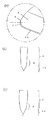
また、図2(a)は、本発明のセラミック製包丁の刃部3における刃先部の部分拡大側面図、同図(b)、(c)はその断面図である。
FIG. 2 (a) is a partially enlarged side view of the blade tip portion of the
ここで、本発明のセラミック製包丁1は、少なくとも上記切刃稜辺4から円弧状先端稜辺7の曲率が終了する点9にかけて上記大刃6に連続して小刃10を形成したことが重要である。
Here, in the
従来、この小刃10は円弧状先端稜辺7まで備えたものはなく、この大刃6に連続した小刃10を円弧状先端稜辺7まで設けることで、円弧状先端稜辺7の刃先角度が大きくなり、円弧状先端稜辺7での欠けを大幅に抑制することができる。しかも、切れ味を損なわない小刃10の角度を設定することにより、包丁本来の機能、使い勝手を損なうことがない。また、円弧状先端稜辺7、即ち包丁の刃先の最先端も切刃として使用できるので使い勝手が良く、包丁の先端で食材を切っているときに食材のどこが実際に切れているか実感し易く、飾り切り等の細かい作業を容易に、確実に行うことができる。
Conventionally, there is no
また、上記大刃6、小刃10は、両側面に設けることが好ましいが、一方の側面にのみ設けてもよい。
The
また、大刃6は平面で形成してもよいが、図2(c)に示すように、刃体の強度を持たすとともに、切断した食材等が刃に張り付くのを防ぐため、R400〜R800mmの曲面で形成するのが好ましい。
Moreover, although the
さらに、小刃10は、少なくとも上記切刃稜辺4から円弧状先端稜辺7の曲率が終了する点9にかけて設ければよいが、曲率が終了する点9を越えて形成されていてもよい。
Furthermore, the
またさらに、上記大刃6の角度は1〜5度に設定することが好ましい。
Furthermore, the angle of the
この角度が1度より小さい場合、刃部3の強度が著しく低下し、欠け、折れが頻繁に発生する恐れがある。また、角度が5度より大きい場合には、食材等の切断時の負荷が大きくなり、切れ味が悪化する。
When this angle is smaller than 1 degree, the strength of the
また、小刃10の角度は、20〜45度に設定することが好ましい。小刃の角度が20度より小さい場合、刃先の強度が著しく低下し、刃先の欠けが頻繁に発生する恐れがある。一方、角度が45度より大きい場合には、切れ味が著しく悪化する。
The angle of the
さらに、小刃10は、刃の両側面に設けることが好ましいが、一方の側面にのみ設けてもよい。
Further, the
また、このような小刃10を有するセラミック製包丁1を作製するためには、まず、1.5〜3モル%のイットリア粉末を含むジルコニア粉末に対しアクリル系、ワックス系もしくはPEG系バインダーを2〜10質量%添加し、平均粒径が10〜150ミクロンの顆粒を作成する。次にこの顆粒を金型で成形圧力700〜2000Kg/cm2にて図3に示すような所定形状に成形し、その後、1300〜1500℃で焼成し、ジルコニア焼結体を得る。その後、公知の方法で、刃付けを行う。円弧状先端部に小刃をつける方法は、従来通り切刃部分に小刃を連続的に形成させながら、先端部に来た際、先端部を中心として回転させるようにして小刃をつけるようにする。
In order to produce the
成形体の成形方法としては上記以外にも、鋳込む方法や可塑成型法(たとえばインジェクション成形法)、ラバープレス法、ホットプレス法等の周知の成形方法を用いても良い。また得られたジルコニア焼結体を1300〜1500℃で焼結後、圧力1500〜2500Kg/cm2で2〜5h保持するいわゆるHIP法を使用することもできる。
As a molding method of the molded body, in addition to the above, a known molding method such as a casting method, a plastic molding method (for example, an injection molding method), a rubber press method, a hot press method, or the like may be used. The so-called HIP method in which the obtained zirconia sintered body is sintered at 1300 to 1500 ° C. and held at a pressure of 1500 to 2500 Kg /
次いで、本発明の実施例について説明する。 Next, examples of the present invention will be described.
先ず、大刃の角度を0.5〜10度、小刃の角度を25〜50度とし、ジルコニアセラミック製の包丁を上述の製造方法によって作製した。得られた包丁における刃先の耐衝撃性試験を行った。 First, the angle of the large blade was set to 0.5 to 10 degrees, the angle of the small blade was set to 25 to 50 degrees, and a knife made of zirconia ceramic was produced by the above-described manufacturing method. The impact resistance test of the blade edge in the obtained kitchen knife was performed.
また、比較例として、小刃を形成していない従来品についても同様の試験を行った。 As a comparative example, a similar test was performed on a conventional product in which a small blade was not formed.
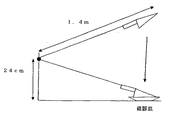
図3に耐衝撃性試験方法を示す。長さ1.4mの棒の一方を回転の中心とし、高さ24cmの位置にスムーズな動きができる様にセットする。もう一方の先端に包丁を固定し、包丁を50cmの高さまで持ち上げ、静かに手を離して、自然落下にて衝突させる。衝突部には磁器製の皿を置く。上記のようにセットすることにより、刃体の中央部または先端が磁器性の皿に衝突することになる。上記衝撃テストを繰り返し30回行い、テスト後の刃先の状態を、「○:変化無し(0.3mmより小さな欠け発生)」、「△:0.3〜1.0mmの欠け発生」、「×:1.0mmより大きな欠け発生」で評価した。 FIG. 3 shows the impact resistance test method. Set one of the 1.4m-long bars as the center of rotation, and set it at a height of 24cm so that it can move smoothly. Fix the kitchen knife to the other end, lift the kitchen knife to a height of 50 cm, gently release your hand and let it collide with natural fall. Place a porcelain dish in the collision area. By setting as described above, the center or tip of the blade body collides with the porcelain dish. The impact test was repeated 30 times, and the state of the blade edge after the test was determined as “◯: no change (occurrence of chipping smaller than 0.3 mm)”, “Δ: generation of chipping of 0.3 to 1.0 mm”, “× : Chipping larger than 1.0 mm ”.
また、これら包丁における切れ味について、モニターによる評価を実施した。モニターとして十名の主婦に評価をお願いした。その結果を、「○:9人以上が切れ味が良いと判断」、「△:5〜8人が切れ味が良いと判断」「×:切れ味が良いと判断した人が4人以下」で評価した。 In addition, the sharpness of these knives was evaluated by a monitor. We asked 10 housewives to evaluate as a monitor. The results were evaluated according to “○: 9 or more people judged that sharpness was good”, “△: 5-8 people judged that sharpness was good”, “×: 4 or less people judged that sharpness was good”. .
衝撃性試験、切れ味テストの結果を表1に示す。衝撃性試験結果より、大刃角が1度より小さい場合、あるいは小刃角が30度より小さい場合に耐衝撃性が低下することが確認できる。また、切れ味テスト結果より、大刃角が5度より大きい場合、あるいは小刃角が45度より大きい場合に切れ味が悪化することが確認できる。 Table 1 shows the results of the impact test and the sharpness test. From the impact test results, it can be confirmed that the impact resistance decreases when the large blade angle is smaller than 1 degree or when the small blade angle is smaller than 30 degrees. In addition, from the sharpness test result, it can be confirmed that the sharpness deteriorates when the large blade angle is larger than 5 degrees or when the small blade angle is larger than 45 degrees.
以上の結果から、大刃角1〜5度、小刃角30〜45度にそれぞれ設定することによって、耐衝撃性、切れ味ともに兼ね備えることができることが分かる。

1・・セラミック製包丁
2・・柄部
3・・刃部
4・・切刃稜辺
5・・背面稜辺
6・・大刃
7・・円弧状先端稜辺
8・・大刃粗面部
9・・曲率の終点
10・・小刃
11・・セラミック製包丁
12・・柄部
13・・刃部
14・・切刃稜辺
15・・背面稜辺
16・・大刃
17・・円弧状先端稜辺
18・・大刃粗面部
1. ・
Claims (8)
Priority Applications (1)
| Application Number | Priority Date | Filing Date | Title |
|---|---|---|---|
| JP2006049181A JP2006271959A (en) | 2005-03-03 | 2006-02-24 | Ceramic knife |
Applications Claiming Priority (2)
| Application Number | Priority Date | Filing Date | Title |
|---|---|---|---|
| JP2005059108 | 2005-03-03 | ||
| JP2006049181A JP2006271959A (en) | 2005-03-03 | 2006-02-24 | Ceramic knife |
Related Child Applications (1)
| Application Number | Title | Priority Date | Filing Date |
|---|---|---|---|
| JP2012110471A Division JP2012148160A (en) | 2005-03-03 | 2012-05-14 | Ceramic edged tool |
Publications (1)
| Publication Number | Publication Date |
|---|---|
| JP2006271959A true JP2006271959A (en) | 2006-10-12 |
Family
ID=37207248
Family Applications (1)
| Application Number | Title | Priority Date | Filing Date |
|---|---|---|---|
| JP2006049181A Pending JP2006271959A (en) | 2005-03-03 | 2006-02-24 | Ceramic knife |
Country Status (1)
| Country | Link |
|---|---|
| JP (1) | JP2006271959A (en) |
Cited By (3)
| Publication number | Priority date | Publication date | Assignee | Title |
|---|---|---|---|---|
| JP2012148160A (en) * | 2005-03-03 | 2012-08-09 | Kyocera Corp | Ceramic edged tool |
| JP6427699B1 (en) * | 2018-03-26 | 2018-11-21 | 株式会社レーベン販売 | Cookware and method of manufacturing the same |
| WO2024069386A1 (en) * | 2022-09-29 | 2024-04-04 | 武汉苏泊尔炊具有限公司 | Knife and manufacturing method therefor |
Citations (8)
| Publication number | Priority date | Publication date | Assignee | Title |
|---|---|---|---|---|
| GB488543A (en) * | 1938-02-26 | 1938-07-08 | Albert Thomas Lees | Improvements in or relating to knife blades |
| JPS412785Y1 (en) * | 1964-05-14 | 1966-02-19 | ||
| JPS60164369U (en) * | 1984-04-09 | 1985-10-31 | 株式会社 井之口刃物製作所 | knife |
| JPS61159982A (en) * | 1984-12-29 | 1986-07-19 | 京セラ株式会社 | Kitchen knife made of zirconia ceramic |
| JPH0318394A (en) * | 1989-06-15 | 1991-01-25 | Hasegawa Hamono Kk | Cutlery such as kitchen knife or the like and manufacture of the same |
| JPH079263U (en) * | 1993-05-25 | 1995-02-10 | 株式会社貝印刃物開発センター | Structure to prevent blades from sticking to blades |
| JPH1199287A (en) * | 1997-09-26 | 1999-04-13 | Ryota Hirai | Edged tool made by powder metallurgy |
| JP3084623U (en) * | 2001-09-11 | 2002-03-29 | 下村企販株式会社 | Kitchen knife |
-
2006
- 2006-02-24 JP JP2006049181A patent/JP2006271959A/en active Pending
Patent Citations (8)
| Publication number | Priority date | Publication date | Assignee | Title |
|---|---|---|---|---|
| GB488543A (en) * | 1938-02-26 | 1938-07-08 | Albert Thomas Lees | Improvements in or relating to knife blades |
| JPS412785Y1 (en) * | 1964-05-14 | 1966-02-19 | ||
| JPS60164369U (en) * | 1984-04-09 | 1985-10-31 | 株式会社 井之口刃物製作所 | knife |
| JPS61159982A (en) * | 1984-12-29 | 1986-07-19 | 京セラ株式会社 | Kitchen knife made of zirconia ceramic |
| JPH0318394A (en) * | 1989-06-15 | 1991-01-25 | Hasegawa Hamono Kk | Cutlery such as kitchen knife or the like and manufacture of the same |
| JPH079263U (en) * | 1993-05-25 | 1995-02-10 | 株式会社貝印刃物開発センター | Structure to prevent blades from sticking to blades |
| JPH1199287A (en) * | 1997-09-26 | 1999-04-13 | Ryota Hirai | Edged tool made by powder metallurgy |
| JP3084623U (en) * | 2001-09-11 | 2002-03-29 | 下村企販株式会社 | Kitchen knife |
Cited By (3)
| Publication number | Priority date | Publication date | Assignee | Title |
|---|---|---|---|---|
| JP2012148160A (en) * | 2005-03-03 | 2012-08-09 | Kyocera Corp | Ceramic edged tool |
| JP6427699B1 (en) * | 2018-03-26 | 2018-11-21 | 株式会社レーベン販売 | Cookware and method of manufacturing the same |
| WO2024069386A1 (en) * | 2022-09-29 | 2024-04-04 | 武汉苏泊尔炊具有限公司 | Knife and manufacturing method therefor |
Similar Documents
| Publication | Publication Date | Title |
|---|---|---|
| JP2012148160A (en) | Ceramic edged tool | |
| KR100874694B1 (en) | Sharp cutting tools | |
| JPWO2011090066A1 (en) | Blade structure for a blade and a blade provided with the blade structure | |
| EP1207212A3 (en) | Nickel alloy composition | |
| CN101657303A (en) | Cutting eleemnt, electric shaver provided with a cutting element and method for producing such element | |
| JP2010154981A (en) | Carbide bar for dental technology | |
| JP2006271959A (en) | Ceramic knife | |
| CN205286554U (en) | Cermet dentistry bistrique | |
| US6447569B1 (en) | Diamond containing edge material | |
| JP3905062B2 (en) | Ceramic knife | |
| CN113352353B (en) | Bimetal composite cutter and manufacturing method thereof | |
| JPH0649111B2 (en) | Zirconia ceramic knife | |
| JPS605401B2 (en) | Cutting tools | |
| JPS59108585A (en) | Ceramic scisiors | |
| JP2001029672A (en) | Bread cutting knife made of ceramics | |
| JPH1199287A (en) | Edged tool made by powder metallurgy | |
| KR20180107667A (en) | A knife | |
| JP7108049B2 (en) | kitchen knife and blade | |
| JP2007168001A (en) | Knife edge sharpening auxiliary implement | |
| CN214819845U (en) | Novel cambered surface processing single crystal cutter | |
| JP4518666B2 (en) | Grater | |
| JP6905668B2 (en) | A cutting blade for forming a slit and a method for manufacturing a rubber valve for medical use with a slit using the cutting blade. | |
| CN207205472U (en) | A kind of dome screw tap | |
| KR102030057B1 (en) | Knives that can be used for a long time without food sticking | |
| CN211839958U (en) | High-strength upper-lower matching cutter assembly |
Legal Events
| Date | Code | Title | Description |
|---|---|---|---|
| A621 | Written request for application examination |
Effective date: 20080818 Free format text: JAPANESE INTERMEDIATE CODE: A621 |
|
| A977 | Report on retrieval |
Effective date: 20110531 Free format text: JAPANESE INTERMEDIATE CODE: A971007 |
|
| A131 | Notification of reasons for refusal |
Effective date: 20110607 Free format text: JAPANESE INTERMEDIATE CODE: A131 |
|
| A521 | Written amendment |
Effective date: 20110802 Free format text: JAPANESE INTERMEDIATE CODE: A523 |
|
| A02 | Decision of refusal |
Free format text: JAPANESE INTERMEDIATE CODE: A02 Effective date: 20120214 |
|
| A521 | Written amendment |
Free format text: JAPANESE INTERMEDIATE CODE: A523 Effective date: 20120514 |
|
| A911 | Transfer of reconsideration by examiner before appeal (zenchi) |
Effective date: 20120521 Free format text: JAPANESE INTERMEDIATE CODE: A911 |
|
| A912 | Removal of reconsideration by examiner before appeal (zenchi) |
Effective date: 20120928 Free format text: JAPANESE INTERMEDIATE CODE: A912 |