JP2006248564A - Packaging material container - Google Patents
Packaging material container Download PDFInfo
- Publication number
- JP2006248564A JP2006248564A JP2005066701A JP2005066701A JP2006248564A JP 2006248564 A JP2006248564 A JP 2006248564A JP 2005066701 A JP2005066701 A JP 2005066701A JP 2005066701 A JP2005066701 A JP 2005066701A JP 2006248564 A JP2006248564 A JP 2006248564A
- Authority
- JP
- Japan
- Prior art keywords
- film roll
- film
- container
- packaging material
- material container
- Prior art date
- Legal status (The legal status is an assumption and is not a legal conclusion. Google has not performed a legal analysis and makes no representation as to the accuracy of the status listed.)
- Granted
Links
Images



Classifications
-
- B—PERFORMING OPERATIONS; TRANSPORTING
- B65—CONVEYING; PACKING; STORING; HANDLING THIN OR FILAMENTARY MATERIAL
- B65B—MACHINES, APPARATUS OR DEVICES FOR, OR METHODS OF, PACKAGING ARTICLES OR MATERIALS; UNPACKING
- B65B41/00—Supplying or feeding container-forming sheets or wrapping material
- B65B41/12—Feeding webs from rolls
Landscapes
- Engineering & Computer Science (AREA)
- Mechanical Engineering (AREA)
- Containers And Plastic Fillers For Packaging (AREA)
- Storage Of Web-Like Or Filamentary Materials (AREA)
- Packaging Of Machine Parts And Wound Products (AREA)
- Details Of Rigid Or Semi-Rigid Containers (AREA)
Abstract
【課題】 輸送中における衝撃や損傷からフィルムロールを保護するとともに、納入後はそのまま包装機へ装填することが可能なフィルムロールを入れるための包装材容器を提供する。
【解決手段】 容器10は、フィルムロール9を収納している。容器10は、外壁部10a、2つの側壁部10b、開口部10cおよび一方の側壁部10bに形成された穴部10gを備えている。外壁部10aは、フィルムロール9のフィルム面を覆うように形成された筒状の部材である。側壁部10bは、フィルムロール9の軸芯9aの両端を覆うように形成された板状の部材である。開口部10cは、外壁部10aの一部として形成されており、内部に収納しているフィルムロール9のフィルムFの始端F1を取り出す開口である。穴部10gは、フィルムロール9を容器10ごと製袋包装機3に対して装填する際に、容器10を製袋包装機3に対して固定する。
【選択図】 図4
PROBLEM TO BE SOLVED: To provide a packaging material container for storing a film roll which can be loaded into a packaging machine as it is after delivery, while protecting the film roll from impact and damage during transportation.
A container 10 contains a film roll 9. The container 10 includes an outer wall portion 10a, two side wall portions 10b, an opening portion 10c, and a hole portion 10g formed in one side wall portion 10b. The outer wall portion 10 a is a cylindrical member formed so as to cover the film surface of the film roll 9. The side wall portion 10b is a plate-like member formed so as to cover both ends of the shaft core 9a of the film roll 9. The opening part 10c is formed as a part of the outer wall part 10a, and is an opening for taking out the starting end F1 of the film F of the film roll 9 accommodated therein. The hole 10g fixes the container 10 to the bag making and packaging machine 3 when the film roll 9 is loaded into the bag making and packaging machine 3 together with the container 10.
[Selection] Figure 4
Description
本発明は、包装機に対して装填されるフィルムロールを内部に収納する包装材容器に関する。 The present invention relates to a packaging material container that houses therein a film roll loaded into a packaging machine.
従来より、樹脂製の長尺のフィルムを巻き付けたフィルムロールからフィルムを引き出して食品等の商品の包装を行う包装機が用いられている。 2. Description of the Related Art Conventionally, a packaging machine that draws a film from a film roll wound with a long resin film and packages products such as foods has been used.
例えば、特許文献1および特許文献2には、包装機に装填されるフィルムロールについて、段ボール等の包装紙によって包まれた状態で輸送用の箱の中に入れて搬送することが開示されている。このように、使用前のフィルムロールを箱に入れて輸送することで、物流時におけるフィルムロールへの異物の混入やフィルムロールの損傷等の問題の発生を防止することができる。
しかしながら、上記従来のフィルムロールでは、以下に示すような問題点を有している。 However, the conventional film roll has the following problems.
すなわち、上記公報に開示されたフィルムロールでは、納入した包装紙に包まれた状態のフィルムロールを輸送用の箱から出して、さらに段ボール等の包装紙を開封して取り出してから装填作業に入ることになる。このため、包装機へ自動装填する際には、人手によって1ロール数十キログラムにもなるフィルムロールを箱から取り出す等の重労働の作業が必要になる。そして、フィルムロールを保護するための包装紙や箱は、フィルムロールを取り出した後ではゴミとなり処分しなくてはならないという問題が生じる。 That is, in the film roll disclosed in the above publication, the film roll wrapped in the delivered wrapping paper is taken out of the transport box, and the wrapping paper such as cardboard is further opened and taken out before the loading operation is started. It will be. For this reason, when loading automatically into a packaging machine, work of heavy labor, such as taking out the film roll which becomes several dozen kilograms of one roll manually from a box, is needed. And the wrapping paper and box for protecting a film roll become a garbage after taking out a film roll, and the problem that it must be disposed has arisen.
本発明の課題は、輸送中における衝撃や損傷からフィルムロールを保護するとともに、納入後はそのまま包装機へ装填することが可能なフィルムロールを入れるための包装材容器を提供することにある。 The subject of this invention is providing the packaging material container for putting the film roll which can be loaded into a packaging machine as it is after delivery while protecting a film roll from the impact and damage in transportation.
第1の発明に係る包装材容器は、フィルムロールを収納するための包装材容器であって、外壁部と、開口部と、側壁部と、固定部と、を備えている。外壁部は、フィルムロールの外周を覆っている。開口部は、外壁部に形成されており、フィルムロールの始端が取り出される。側壁部は、フィルムロールの中心軸方向の両側を覆うようにそれぞれ設けられており、少なくとも一方においてフィルムロールの中心軸を回転可能な状態で支持する。固定部は、フィルムロールを装填する包装機に対して取り付けられる。 The packaging material container which concerns on 1st invention is a packaging material container for accommodating a film roll, Comprising: The outer wall part, the opening part, the side wall part, and the fixing | fixed part are provided. The outer wall portion covers the outer periphery of the film roll. The opening is formed in the outer wall, and the starting end of the film roll is taken out. The side wall portions are respectively provided so as to cover both sides of the film roll in the central axis direction, and support the central axis of the film roll in a rotatable state at at least one side. The fixing portion is attached to a packaging machine for loading a film roll.
ここでは、フィルムロールの始端を取り出すための開口が形成された外壁部と、フィルムロールの中心軸を支持する側壁部とを有する包装材容器にフィルムロールを収納する。そして、包装機に装填する際には、側壁部あるいは外壁部に形成された固定部によって包装機に固定される。 Here, the film roll is accommodated in a packaging material container having an outer wall portion in which an opening for taking out the starting end of the film roll is formed and a side wall portion supporting the central axis of the film roll. And when loading to a packaging machine, it fixes to a packaging machine with the fixing | fixed part formed in the side wall part or the outer wall part.
ここで、外壁部に形成された開口部は、フィルムロールの取り出し口として形成されたものであり、フィルムの厚みより若干大きい開口であればよい。固定部は、包装機に対してフィルムロールを包装材容器ごと取り付ける際に用いられる部材であって、側壁部あるいは外壁部に形成されている。そして、フィルムロールの中心軸は、フィルムが巻かれた芯材に相当するものであって、包装機に装填後にはこの中心軸を中心にしてフィルムロールを回転させることで長尺のフィルムを包装機へ供給する。 Here, the opening formed in the outer wall is formed as a film roll outlet and may be an opening that is slightly larger than the thickness of the film. The fixing portion is a member used when the film roll is attached to the packaging machine together with the packaging material container, and is formed on the side wall portion or the outer wall portion. The central axis of the film roll corresponds to the core around which the film is wound. After loading the packaging machine, the film roll is rotated around the central axis to wrap a long film. Supply to the machine.
これにより、納入したフィルムロールを包装材容器を開封することなくそのまま包装機に対して装填し、開口からフィルムロールの始端を取り出して運転を開始することができる。この結果、納入時から全く人手を介すことなく行われる完全自動装填システムに適した包装材容器を提供することができる。また、包装材容器をそのまま包装機に取り付けて再利用することで、従来のような箱や梱包材等のゴミの発生をなくすことができる。さらに、搬入から装填されるまでの間に包装材容器を開封することなく包装機へ取り付けられるため、収納したフィルムロールの品質を保持したまま包装機に取り付けることができる。 Thereby, the delivered film roll can be loaded into the packaging machine as it is without opening the packaging material container, and the operation can be started by taking out the starting end of the film roll from the opening. As a result, it is possible to provide a packaging material container suitable for a fully automatic loading system that is performed without any manual intervention from the time of delivery. Further, by attaching the packaging material container to the packaging machine as it is and reusing it, it is possible to eliminate the generation of dust such as conventional boxes and packaging materials. Furthermore, since it is attached to a packaging machine without opening a packaging material container between carrying in and loading, it can attach to a packaging machine, maintaining the quality of the accommodated film roll.
なお、包装材容器の形状としては、収納するフィルムロールの形状に合わせて円筒形としてもよいし、輸送中等における操作性を考慮して直方体形状あるいは底面が多角形の筒形であってもよい。 The shape of the packaging material container may be a cylindrical shape in accordance with the shape of the film roll to be accommodated, or may be a rectangular parallelepiped shape or a cylindrical shape having a polygonal bottom surface in consideration of operability during transportation or the like. .
第2の発明に係る包装材容器は、第1の発明に係る包装材容器であって、フィルムロールの回転を禁止する回転禁止部材をさらに備えている。 The packaging material container which concerns on 2nd invention is a packaging material container which concerns on 1st invention, Comprising: The rotation prohibiting member which prohibits rotation of a film roll is further provided.
ここでは、包装材容器内におけるフィルムロールの回転を回転禁止部材によって一時的に禁止する。 Here, the rotation of the film roll in the packaging material container is temporarily prohibited by the rotation prohibiting member.
これにより、包装材容器内でフィルムロールを回転させたくない場合、例えば、フィルムロールの輸送中や包装機への装填中等においては回転禁止部材を用いてフィルムロールの回転を禁止することができる。そして、装填後にはこの回転禁止部材による回転禁止を解除することで、スムーズに包装機の運転を開始させることができる。 Thereby, when it is not desired to rotate the film roll in the packaging material container, for example, the rotation of the film roll can be prohibited using the rotation prohibiting member during transportation of the film roll or loading into the packaging machine. Then, after the loading, the rotation prohibition by the rotation prohibiting member is canceled, so that the operation of the packaging machine can be started smoothly.
なお、回転禁止部材は、フィルムロールの側面(フィルム面)に対して当接するような部材であってもよいし、フィルムロールの中心軸の側壁部に対する回転を禁止するような部材であってもよい。 The rotation prohibiting member may be a member that abuts against the side surface (film surface) of the film roll, or may be a member that prohibits rotation of the film roll with respect to the side wall portion of the central axis. Good.
第3の発明に係る包装材容器は、第1または第2の発明に係る包装材容器であって、フィルムロールの始端は、開口部の近傍において保持されている。 The packaging material container which concerns on 3rd invention is a packaging material container which concerns on 1st or 2nd invention, Comprising: The starting end of the film roll is hold | maintained in the vicinity of the opening part.
ここでは、包装材容器に形成された開口部においてフィルムロールの始端(フィルムの先端部分)を保持している。 Here, the opening end formed in the packaging material container holds the starting end of the film roll (the leading end portion of the film).
これにより、包装材容器に収納されたまま包装機に対して装填されたフィルムロールの始端を自動的に取り出して運転を開始させることができる。この結果、さらに効率よく人手を介さないで自動装填を行うことができる。 Thereby, the start end of the film roll loaded with respect to the packaging machine with being accommodated in the packaging material container can be automatically taken out and the operation can be started. As a result, automatic loading can be performed more efficiently without human intervention.
なお、フィルムロールの始端の保持は、例えば、比較的粘着力が小さい両面テープやミクロ吸盤等によって包装材容器における開口部付近に仮固定することにより行うことができる。 In addition, holding | maintenance of the start end of a film roll can be performed by temporarily fixing to the opening part vicinity of a packaging material container with a double-sided tape, a micro sucker, etc. with comparatively small adhesive force, for example.
第4の発明に係る包装材容器は、第1から第3の発明のいずれか1つに係る包装材容器であって、フィルムロールの幅方向に移動可能な移動側壁部をさらに備えている。 A packaging material container according to a fourth aspect of the present invention is the packaging material container according to any one of the first to third aspects of the present invention, and further includes a movable side wall portion movable in the width direction of the film roll.
ここでは、フィルムロールの幅に応じて容器内で移動可能な移動側壁部を設けている。 Here, the movable side wall part which can move within a container according to the width | variety of a film roll is provided.
通常、種類の異なるフィルムロールを収納する際には、フィルムロールの幅が異なる場合もあるためにその幅ごとに異なるサイズの包装材容器を作製する必要がある。 Usually, when storing different types of film rolls, the widths of the film rolls may be different, so it is necessary to produce packaging materials containers of different sizes for each width.
しかし、本発明では、包装材容器の内部においてフィルムロールの幅方向に移動可能な移動側壁部を設けている。このため、1種類の包装材容器であっても、幅の異なる多種多様なフィルムロールを収納することが可能になる。 However, in this invention, the movable side wall part which can move to the width direction of a film roll is provided in the inside of a packaging material container. For this reason, even if it is one type of packaging material container, it becomes possible to accommodate a wide variety of film rolls having different widths.
第5の発明に係る包装材容器は、第1から第4の発明のいずれか1つに係る包装材容器であって、固定部は、側壁部に形成されている。 A packaging material container according to a fifth invention is the packaging material container according to any one of the first to fourth inventions, wherein the fixing portion is formed on the side wall portion.
ここでは、包装機に対してフィルムロールを装填する際に包装機への固定に用いられる固定部を、包装材容器の側壁部に形成している。 Here, the fixing portion used for fixing to the packaging machine when the film roll is loaded into the packaging machine is formed on the side wall of the packaging material container.
これにより、包装機に対してフィルムロールを自動装填する際には、側壁部側を包装機に対して押し付けるようにして移動させることで容易に包装機への取付けを行うことができる。 Thereby, when loading a film roll with respect to a packaging machine automatically, attachment to a packaging machine can be easily performed by moving it so that a side wall part side may be pressed with respect to a packaging machine.
第6の発明に係る包装材容器は、第1から第5の発明のいずれか1つに係る包装材容器であって、固定部は、包装機に形成された爪部材を引っ掛ける穴部を有している。 A packaging material container according to a sixth invention is the packaging material container according to any one of the first to fifth inventions, wherein the fixing portion has a hole portion for hooking a claw member formed in the packaging machine. is doing.
ここでは、包装機に形成された爪部材に、包装材容器の穴部を引っ掛けて固定する。つまり、爪部材と穴部とを組み合わせて包装材容器を包装機に対して固定する。 Here, the hole part of a packaging material container is hooked and fixed to the nail | claw member formed in the packaging machine. That is, the packaging material container is fixed to the packaging machine by combining the claw member and the hole.
これにより、簡易な構成によって、フィルムロールを収納した包装材容器をそのまま包装機へ簡単に取り付けることができる。この結果、フィルムロールの自動装填にさらに適した包装材容器を提供することができる。 Thereby, the packaging material container which accommodated the film roll can be simply attached to a packaging machine as it is with a simple configuration. As a result, it is possible to provide a packaging material container more suitable for automatic loading of film rolls.
第7の発明に係る包装材容器は、第1から第6の発明のいずれか1つに係る包装材容器であって、収納しているフィルムロールに関する情報を記憶する記憶部をさらに備えている。 A packaging material container according to a seventh aspect of the present invention is the packaging material container according to any one of the first to sixth aspects of the present invention, further comprising a storage unit for storing information relating to the stored film roll. .
ここでは、収納しているフィルムロールに関する情報を記憶させるIDタグ等の記憶部をさらに備えている。ここで、フィルムロールに関する情報とは、フィルムロールの材質、幅(サイズ)、残量、搬入日等の情報が挙げられる。 Here, a storage unit such as an ID tag for storing information on the film roll stored therein is further provided. Here, the information regarding the film roll includes information such as the material, width (size), remaining amount, and carry-in date of the film roll.
これにより、例えば、フィルムロールのフィルムの残量を記憶した記憶部を取り付けておくことで、フィルムロールの在庫管理が容易になる。 Thereby, for example, stock management of the film roll is facilitated by attaching a storage unit that stores the film remaining amount of the film roll.
第8の発明に係る包装材容器は、第1から第7の発明のいずれか1つに係る包装材容器であって、フィルムロールのフィルムの残量を表示する残量表示部をさらに備えている。 A packaging material container according to an eighth invention is the packaging material container according to any one of the first to seventh inventions, further comprising a remaining amount display unit for displaying the remaining amount of the film of the film roll. Yes.
ここでは、包装材容器の外壁部等の面に、収納しているフィルムロールの残量を表示する残量表示部を設けている。ここで、この残量表示部としては、小型の液晶パネル等を用いることができる。 Here, the remaining amount display part which displays the residual amount of the film roll accommodated in surfaces, such as the outer wall part of a packaging material container, is provided. Here, a small liquid crystal panel or the like can be used as the remaining amount display section.
これにより、常に包装材容器に収納されている状態であっても、フィルムロールのフィルム残量を一目で把握することができるため、フィルムロールの在庫管理が容易になる。 Thereby, even if it is a state always stored in the packaging material container, since the film remaining amount of the film roll can be grasped at a glance, stock management of the film roll becomes easy.
なお、この残量表示部は、上述したIDタグ等の記憶部に接続されていることがより好ましい。この場合には、記憶部から読み出したデータに基づいてフィルム残量の表示を行うことができる。 The remaining amount display unit is more preferably connected to the storage unit such as the ID tag described above. In this case, the remaining film amount can be displayed based on the data read from the storage unit.
第9の発明に係る包装材容器は、第1から第8の発明のいずれか1つに係る包装材容器であって、外壁部および側壁部の少なくとも一方は透明な材料によって形成されている。 A packaging material container according to a ninth aspect is the packaging material container according to any one of the first to eighth aspects, wherein at least one of the outer wall part and the side wall part is formed of a transparent material.
ここでは、包装材容器の一部あるいは全部が樹脂等の透明な材料によって形成されている。 Here, a part or all of the packaging material container is formed of a transparent material such as a resin.
これにより、常に包装材容器内に収納された状態で使用されるフィルムロールであっても、外部からフィルムロールを確認することができるため、在庫管理等がし易くなる。また、透明な材料に光触媒等を混練して外壁部等を形成した場合には、光を照射することにより包装材容器の内部を殺菌してフィルムロールを常に清潔に保つことができる。 Thereby, even if it is a film roll always used in the state accommodated in the packaging material container, since a film roll can be confirmed from the outside, inventory management etc. become easy. Further, when the outer wall or the like is formed by kneading a photocatalyst or the like with a transparent material, the film roll can be kept clean by sterilizing the inside of the packaging material container by irradiating light.
第10の発明に係る包装材容器は、第1から第9の発明のいずれか1つに係る包装材容器であって、フィルムロールの温度を管理する保温部をさらに備えている。 A packaging material container according to a tenth aspect of the invention is the packaging material container according to any one of the first to ninth aspects, further comprising a heat retaining unit that manages the temperature of the film roll.
ここでは、収納しているフィルムロールの温度を管理する保温部を設けている。ここで、保温部としては、熱風ファン等を用いることができる。 Here, a heat retaining unit for managing the temperature of the film roll stored therein is provided. Here, a hot air fan etc. can be used as a heat retention part.
これにより、温度変化や湿度の変化に対して悪影響を受けるフィルムを巻き付けたフィルムロールであっても、包装材容器内における温湿度の管理を自動的に行うことができるため、温湿度変化によるフィルムへの悪影響を排除して常に高品質な状態に保つことができる。 As a result, even if a film roll is wound with a film that is adversely affected by changes in temperature and humidity, the temperature and humidity can be automatically managed in the packaging material container. It is possible to always maintain a high quality state by eliminating adverse effects on the product.
本発明の包装材容器によれば、納入したフィルムロールを包装材容器を開封することなくそのまま包装機に対して装填することができ、納入時から全く人手を介すことなく行われる完全自動装填システムに適した包装材容器を提供することができるとともに、包装材容器をそのまま包装機に取り付けて再利用することでゴミの発生をなくし、収納したフィルムロールの品質を保持したまま包装機に取り付けることができる。 According to the packaging material container of the present invention, the delivered film roll can be loaded into the packaging machine as it is without opening the packaging material container, and fully automatic loading is performed without any manual intervention from the time of delivery. A packaging container suitable for the system can be provided, and the packaging container can be attached to the packaging machine as it is to eliminate the generation of dust and can be attached to the packaging machine while maintaining the quality of the stored film roll. be able to.
本発明の一実施形態に係る包装材容器について、図1〜図6(b)を用いて説明すれば以下の通りである。 A packaging material container according to an embodiment of the present invention will be described below with reference to FIGS.
[製袋包装機3の構成]
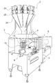
本実施形態のフィルムロール用の容器(包装材容器)10(図4参照)に収納されたフィルムロール9を装填する製袋包装機3は、図1に示すように、被包装物となるポテトチップス等の食品をフィルムで覆い、筒状となったフィルムを縦横にシールして袋を製造する装置である。
[Configuration of bag making and packaging machine 3]
As shown in FIG. 1, a bag making and
被包装物は、製袋包装機3の上方に設けられた計量機2から、原則として所定量ずつ落下してくる。計量機2は、フィーダ、プールホッパ24、計量ホッパ25、集合排出シュート26などから構成される組合せ計量装置である。
In principle, the articles to be packaged fall from the weighing
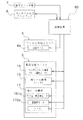
製袋包装機3は、被包装物の袋詰めを行う本体部分である製袋包装ユニット5(図3参照)と、この製袋包装ユニット5に袋となるフィルムFを供給するフィルム供給ユニット6と、両ユニット5,6の駆動部分の動きを制御する制御装置90(図2参照)とから構成されている。
The bag making and
[フィルム供給ユニット6]
フィルム供給ユニット6は、製袋包装ユニット5の成形機構13(図3参照)に対してシート状のフィルムFを供給するユニットであって、製袋包装ユニット5に隣接して設けられている。このフィルム供給ユニット6では、フィルムFが巻かれたフィルムロール9が図示しない搬送装置によってストック場所から搬送された後、例えば、図11に示す仮受け部60等を用いて容器10ごと自動的に装填される。そして、容器10内に収納されたフィルムロール9からフィルムFが繰り出される。
[Film supply unit 6]
The
フィルムロール9から繰り出されるフィルムFは、容器10に収納されたフィルムロール9を回転させる送出モータ6a(図2参照)の作動により送り出され、製袋包装ユニット5のプルダウンベルト機構14の作動により製袋包装ユニット5側に引っ張られて搬送される。
The film F fed out from the
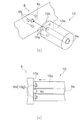
また、フィルム供給ユニット6には、図4(a)等に示すように、フィルムロール9が容器10に収納されたままの状態で自動的に装填される。なお、フィルム供給ユニット6には、後述するフィルムロール9の容器10に形成された穴部10g(図6(a)等参照)に挿入される3本の爪部材6bと、フィルムロール9の軸芯9aを回転駆動する駆動部6cが、フィルムロール9の取付部分の面から突出している。爪部材6bは、先端部分が太くなるように形成されており、フィルムロール9の取付け時にはこの先端部分が弾性変形することで挿入、保持される。駆動部6cは、フィルムロール9の軸芯9aの部分に嵌合してフィルムロール9の軸芯9aに対して回転駆動力を付与する。なお、フィルムロール9およびフィルムロール9を収納した容器10の構成については、後段にて詳述する。
Further, as shown in FIG. 4A and the like, the
[製袋包装ユニット5]
製袋包装ユニット5は、図3に示すように、シート状で送られてくるフィルムFを筒状に成形する成形機構13と、筒状となったフィルムF(以下、筒状フィルムFmという。)を下方に搬送するプルダウンベルト機構14と、筒状フィルムFmの重なり部分を縦にシールする縦シール機構15と、筒状フィルムFmを横にシールすることで袋Bの上下の端部を封止する横シール機構17とを有している。
[Bag making and packaging unit 5]
As shown in FIG. 3, the bag making and
<成形機構13>
成形機構13は、チューブ13bと、フォーマー13aとを有している。チューブ13bは、円筒形状の部材であり、上下端が開口している。このチューブ13bの上端の開口部には、計量機2で計量された被包装物Cが投入される。フォーマー13aは、チューブ13bを取り囲むように配置されている。このフォーマー13aの形状は、フィルムロール9から繰り出されてきたシート状のフィルムFがフォーマー13aとチューブ13bとの間を通るときに筒状に成形されるような形状となっている(図3参照)。また、成形機構13のチューブ13bやフォーマー13aは、製造する袋の大きさに応じて取り替えることができる。
<
The forming
<プルダウンベルト機構14>
プルダウンベルト機構14は、チューブ13bに巻き付いた筒状フィルムFmを吸着して下方に搬送する機構であり、図3に示すように、チューブ13bを挟んで左右両側にそれぞれベルト14cが設けられている。プルダウンベルト機構14では、吸着機能を有するベルト14cを駆動ローラ14aおよび従動ローラ14bによって回して筒状フィルムFmを下方に運ぶ。なお、図3においては、駆動ローラ14a等を回転させるローラ駆動モータの図示を省略している。
<Pull-down
The pull-down
<縦シール機構15>
縦シール機構15は、チューブ13bに巻き付いた筒状フィルムFmの重なり部分を、一定の圧力でチューブ13bに押しつけながら加熱して縦にシールする機構である。この縦シール機構15は、チューブ13bの正面側に位置しており、ヒータや、そのヒータにより加熱され筒状フィルムFmの重なり部分に接触するヒータベルトを有している。また、縦シール機構15は、図示しないが、ヒータベルトをチューブ13bに近づけたり遠ざけたりするための駆動装置も備えている。
<
The
<横シール機構17>
横シール機構17は、成形機構13、プルダウンベルト機構14および縦シール機構15の下方に配置されている。横シール機構17は、図3に示すように、ヒータを内蔵する一対のシールジョー55を含む機構である。
<
The
一対のシールジョー55は、互いに押しつけ合うようにして筒状フィルムFmを挟持し、袋の上下のそれぞれの端部となる筒状フィルムFmの一部に圧力および熱を加えてシールを施す。
The pair of sealing
[制御装置90]
制御装置90は、計量機2の制御および製袋包装機3の制御を行う装置であって、CPU、ROM、RAM等によって構成されている。制御装置90は、図1および図2に示す操作スイッチ類7やタッチパネル式ディスプレイ8から入力された操作や設定に従って、フィルム供給ユニット6において容器10に収納されたフィルムロール9を回転させてフィルムFを繰り出させる送出モータ6aや、製袋包装ユニット5の各機構の駆動部分などを制御する。また、制御装置90は、計量機2のフィーダ、プールホッパ24、計量ホッパ25などの駆動を制御する。さらに、制御装置90は、計量機2および製袋包装機3にある各種センサから必要な情報を取り込み、その情報を各種制御において利用する。
[Control device 90]
The
また、制御装置90は、連続的に計量および製袋包装を行う連続運転制御に加え、間欠的に計量および製袋包装を行う間欠運転制御を行うことができる。間欠運転制御では、製袋包装機3において、フィルム供給ユニット6から間欠的にフィルムFが製袋包装ユニット5へと供給され、製袋包装ユニット5において袋が間欠的に製造される。
Moreover, the
そして、制御装置90は、揺動機構170の揺動用モータ172aの制御において、原則として、揺動用モータ172aを正転させる第1制御モードと揺動用モータ172aを逆転させる第2制御モードとを繰り返す。しかし、第1制御モードあるいは第2制御モードだけにより適切な揺動制御が可能な場合には、揺動用モータ172aを同じ方向に回転させ続ける揺動制御が行われる。
In the control of the
[フィルムロール9]
本実施形態では、製袋包装機3に搭載されるフィルムロールとして、図4(a)および図4(b)に示すように、容器10に収納されたフィルムロール9を用いている。
[Film roll 9]
In this embodiment, as a film roll mounted on the bag making and
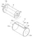
すなわち、本実施形態のフィルムロール9は、図5に示すように、容器10の一方の側壁部10bに長尺のフィルムFを巻き付けた軸芯9aを回転可能な状態で支持されており、容器10の外壁部10aの内部に挿入される。このため、本実施形態のフィルムロール9は、容器10を再利用可能なカートリッジとして用いることができる。よって、フィルムFを全て供給した後にはフィルム加工業者にカートリッジとしての容器10を送り返し、フィルム加工業者において新たなフィルムロール9が容器10にセットされるため、フィルムロール9の包装材等のゴミの発生を抑えて、リサイクル性を向上させることが可能になる。
That is, as shown in FIG. 5, the
そして、フィルムロール9は、図4(a)および図4(b)に示すように、容器10の外壁部10aに形成された開口部10cからフィルムFの始端F1を数cm出した状態で運搬、保管等される。ここで、フィルムロール9の始端F1は、使用されるまでの間においては、容器10の開口部10cから始端F1を外側に出した状態となっている。このため、本実施形態では、製袋包装機3に対して自動的装填された後、フィルムFの始端F1を容易に引き出すことができる。なお、フィルムFの始端F1については、自動装填された際に製袋包装機3に搭載された部材によって取り出し易いように、特殊な形状が施されていてもよい。
Then, as shown in FIGS. 4A and 4B, the
さらに、本実施形態では、運搬中や保管中等においてフィルムFの始端F1が作業の邪魔にならないように、図4(b)に示すように、粘着性部材9cを容器10の外壁部10aの外側の面であって開口部10cの近傍に設けている。これにより、フィルムロール9を使用する前において、容器10の外側に露出したフィルムFの始端F1を仮固定することができる。よって、容器10の開口部10cから出ているフィルムFの始端F1による操作性の悪化を防止できる。
Furthermore, in the present embodiment, the
軸芯9aは、製袋包装機3へ固定される側の一方の側壁部10bの中心から延びる棒状の部材であって、図5に示すように、これに長尺のフィルムFが巻きつけられてフィルムロール9となる。また、軸芯9aは、製袋包装機3に装填されるまでは回転規制部材10hによって側壁部10bに対する相対回転を禁止される。これにより、フィルムロール9の運搬中や保管時において、容器10内でフィルムロール9が回転してフィルムFが損傷する等の問題の発生を回避できる。なお、本実施形態のように、フィルムロール9を自動装填する場合には、この回転規制部材10hは機械的に容易に解除できる構成であることが望ましい。
The
粘着性部材9cは、アクリルエマルジョン等の樹脂に無数の細かい気泡を含ませて形成される厚さ100〜500μmのミクロ吸盤シートを用いることができる。そして、このようなミクロ吸盤を有する粘着性部材9cは、通常のセロハンテープ等の接着力よりも接着力が小さい、いわゆる弱粘性の接着力によってフィルムFの始端F1を仮固定する。これにより、通常時にはフィルムロール9からフィルムFの始端F1が剥がれないようにすることができるとともに、フィルムロール9を自動装填した後にはフィルムロール9からフィルムFの始端F1を剥がし易い程度の接着力により、始端F1をフィルムロール9側で保持することができる。なお、このようなミクロ吸盤シートは、通常の両面テープ等の粘着材と比較して、何度も繰り返し適度な接着力でフィルムFの始端F1を仮固定できる点、粘着成分がフィルムFに残らない点で有利である。
As the
フィルムロール9を収納している容器10は、図4(a)等に示すように、外壁部10a、2つの側壁部10b、開口部10c等を備えている。
As shown in FIG. 4A and the like, the
外壁部10aは、収納するフィルムロール9のフィルム面の周囲を覆うように、アクリルやポリカーボネート等の透明な樹脂によって筒状に形成されている。このため、フィルムロール9を容器10に収納した状態であっても、フィルムロール9のフィルムFの残量や、フィルムロール9の種類、幅等のフィルムロール9に関する情報を外部から一見して把握できる。そして、外壁部10aの外側面には、内部に収納しているフィルムロール9に関する情報を記憶するIDタグ(記憶部)9dや、内部に収納しているフィルムロール9のフィルムFの残量を示す残量表示パネル10fが設けられている。なお、IDタグ9dに記憶されているフィルムロール9に関する情報としては、フィルムロール9の種類、材質、幅、ストック場所への搬入日、フィルム残量等が挙げられる。そして、残量表示パネル10fには、IDタグ9dに記憶されているフィルムFの残量に関するデータに基づいてフィルムFの残量が表示される。また、外壁部10aのフィルム面と対向する内面側は、UVやγ線、薬品等によって洗浄されており、常にフィルムFを清潔な状態で保持することができる。なお、容器10内のフィルムFを常に清潔に保つために、容器10(外壁部10a)を成形する際において酸化チタン(TiO2)等を混練してもよい。これにより、透明な容器10の外部から光を照射することで、酸化チタンの光触媒作用によって容器10内を常に清潔に保つことができる。
The
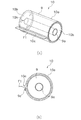
側壁部10bは、フィルムロール9の軸芯9aの両端側をそれぞれ覆うように略円形で形成されており、外壁部10aと同様に、アクリル等の透明な樹脂によって形成されている。側壁部10bは、その外周部分が外壁部10aの内面側に当接するように取り付けられており、開口部10c以外から容器10内への外気の侵入を禁止する。また、外壁部10aから着脱可能な一方の側壁部10bには、図5に示すように、長尺のフィルムFを巻きつけるための軸芯9aが取り付けられている。そして、この一方の外壁部10aの円形の外周部には、突起部10dが形成されている。フィルムロール9を容器10にセットする際には、この突起部10dと、外壁部10aにおける一方の側壁部10bと接触する端部に形成された切欠き部10eとが嵌合するようにセットする。さらに、一方の側壁部10bには、図6(a)および図6(b)に示すように、円形の面側に3つの穴部10gが形成されている。このため、製袋包装機3に対してフィルムロール9を自動的に装填する際には、図6(a)および図6(b)に示す一点鎖線で示す矢印の方向に移動させて製袋包装機3のフィルム供給ユニット6に形成されている爪部材6bをこの穴部10gに挿入するだけで、フィルム供給ユニット6内にフィルムロール9を容器10ごと保持させることができる。
The
なお、外壁部10aおよび側壁部10b等の容器10を構成する部材については、透明樹脂を用いて射出成形機によって成形することができる。
In addition, about the members which comprise
[本容器10の特徴]
(1)
本実施形態の容器10では、図4(a)および図4(b)等に示すように、フィルムロール9を容器10に収納している。そして、容器10は、外壁部10a、2つの側壁部10b、開口部10cおよび一方の側壁部10bに形成された穴部10gを備えている。ここで、外壁部10aは、フィルムロール9のフィルム面を覆うように形成された筒状の部材である。側壁部10bは、フィルムロール9の軸芯9aの両端を覆うように形成された板状の部材である。開口部10cは、外壁部10aの一部として形成されており、内部に収納しているフィルムロール9のフィルムFの始端F1を取り出す開口である。穴部10gは、フィルムロール9を容器10ごと製袋包装機3に対して装填する際に、容器10を製袋包装機3に対して固定するための固定部として機能する。
[Features of the container 10]
(1)
In the
これにより、製袋包装機3に対して装填されるフィルムロール9を、容器10に収納したままで、運搬、搬入、保管、装填を行うことができる。特に、フィルムロール9の装填時においては、フィルムロール9の梱包等を解くことなく、そのまま容器10に収納された状態のままで穴部10g(および爪部材6b)によって装填することができる。このため、運搬から装填までの工程において、梱包用の段ボール等のゴミを一切発生させることなく、容器10内のフィルムロール9を損傷等から保護するとともに、フィルムロール9を自動的に装填することが可能になる。
Thereby, conveyance, carrying in, storage, and loading can be performed with the
(2)
本実施形態の容器10では、図4(a)および図5に示すように、側壁部10bに対するフィルムロール9の相対回転を禁止する回転規制部材10hを有している。
(2)
As shown in FIGS. 4A and 5, the
これにより、フィルムロール9の運搬中や保管時等において、フィルムロール9が容器10内で勝手に回転してしまうことを防止できる。そして、製袋包装機3に装填後には回転規制部材10hを解除することで、フィルムロール9を回転させてフィルムFを供給することが可能になる。よって、装填後の必要時以外における容器10内におけるフィルムロール9の不要な回転によるフィルムFの損傷等を回避できる。
Thereby, it is possible to prevent the
(3)
本実施形態の容器10では、容器10に収納されたフィルムロール9のフィルムFの始端F1が、図4(a)および図4(b)に示すように、容器10の側壁部10aに形成された開口部10cの近傍に保持されている。
(3)
In the
これにより、製袋包装機3へのフィルムロール9の装填後において、すぐにフィルムロール9からフィルムFの始端F1を取り出して運転を開始することができる。また、フィルムロール9が製袋包装機3に装填されるまでにおいては、開口部10cから出ているフィルムFの始端F1を仮固定することで、始端F1が容器10から出ていることによる操作性の低下を防止できる。
Thereby, after loading the
なお、容器10の外部に出ているフィルムFの始端F1については、運搬中や保管中に損傷することも考えられる。しかし、元々フィルムFの始端F1の部分は、製袋包装機3において図示しないスプライサによって前にセットされていたフィルムFの終端と継ぎ合わせられるものであり、商品の包装には使用されないことから特に問題ではない。
In addition, about the start end F1 of the film F which has come out of the
(4)
本実施形態の容器10では、製袋包装機3に対して装填された際に、フィルムロール9を製袋包装機3のフィルム供給ユニット6内に固定する固定部として、一方の側壁部10bに形成された穴部10gを用いている。
(4)
In the
このように、フィルムロール9の軸芯9aの一方の端部を覆うように取り付けられた側壁部10bに固定部としての穴部10gを形成することで、フィルムロール9の装填時には図6(a)および図6(b)に示すように、フィルムロール9を軸芯9aの方向に沿ってそのまま移動させるだけで容易にフィルムロール9を容器10ごと製袋包装機3に固定することができる。よって、単純な取付けが可能になるため、さらに自動装填に適した容器10を提供することができる。
As described above, when the
(5)
本実施形態の容器10では、図5に示すように、収納しているフィルムロール9に関する情報を記憶するIDタグ9dを有している。ここで、IDタグ9dに格納されているフィルムロール9に関する情報には、フィルムロール9の種類、材質、幅、フィルム残量、搬入日等が考えられる。
(5)
As shown in FIG. 5, the
これにより、複数のフィルムロール9を倉庫等において保管する際における在庫管理が容易になる。また、製袋包装機3に対して現在装填されているフィルムロール9を容易に把握することができるため、フィルム残量が少なくなってきた場合には、交換用の新たなフィルムロール9を製袋包装機3の横に準備させておく等の措置を事前にとることができる。よって、自動装填を行う製袋包装機3において、フィルムロール9の交換に要する時間を短縮することで、さらに運転効率を向上させることができる。
This facilitates inventory management when storing a plurality of film rolls 9 in a warehouse or the like. In addition, since the
(6)
本実施形態の容器10では、図5に示すように、収納しているフィルムロール9のフィルム残量を表示する残量表示パネル10fを有している。
(6)
As shown in FIG. 5, the
これにより、例えば、容器10内のフィルムロール9の状態が見えない場合でも、フィルム残量を容易に把握することができるため、在庫管理が容易になる。また、フィルム残量の少ないフィルムロール9については事前に交換用のフィルムロール9を用意しておくことができるため、運転効率を向上させることができる。
Thereby, for example, even when the state of the
(7)
本実施形態の容器10では、外壁部10aおよび側壁部10bが、アクリルやポリカーボネート等の透明な樹脂によって形成されている。
(7)
In the
これにより、容器10に収納しているフィルムロール9の状態(フィルム残量、フィルムFの材質、幅等)を外部から容易に把握できるため、在庫管理が容易になる。
Thereby, since the state (film residual quantity, the material of the film F, the width | variety, etc.) of the
[他の実施形態]
以上、本発明の一実施形態について説明したが、本発明は上記実施形態に限定されるものではなく、発明の要旨を逸脱しない範囲で種々の変更が可能である。
[Other Embodiments]
As mentioned above, although one Embodiment of this invention was described, this invention is not limited to the said embodiment, A various change is possible in the range which does not deviate from the summary of invention.
(A)
上記実施形態では、フィルムロール9を容器10にセットする際には、図5に示すように、容器10の側方側からフィルムロール9の軸芯9aに平行な向きに挿入するあるいは抜き取る例を挙げて説明した。しかし、本発明はこれに限定されるものではない。
(A)
In the above embodiment, when the
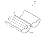
例えば、図7、図8(a)および図8(b)に示すように、容器11に形成された連結部11aを中心にして容器11を2分するように開き、フィルムロール9をセットする容器11であってもよい。
For example, as shown in FIG. 7, FIG. 8A and FIG. 8B, the
(B)
上記実施形態では、図4(a)等に示すように、フィルムロール9を収納した容器10からフィルムFの始端F1を数cm出し、ミクロ吸盤等を用いて容器10の外壁部10aに仮固定した状態で、運搬、保管等を行う例を挙げて説明した。しかし、本発明はこれに限定されるものではない。
(B)
In the above embodiment, as shown in FIG. 4A and the like, the starting end F1 of the film F is taken out several centimeters from the
例えば、運搬、保管中においては、フィルムFの始端F1は容器10の中にあり、製袋包装機3に装填された後、使用する際に初めて開口部10cから始端F1を出すようにしてもよい。
For example, during transportation and storage, the starting end F1 of the film F is in the
ただし、上記実施形態のように、搬送された当初からフィルムFの始端F1が開口部10cから外へ出ていることは、フィルムロール9の自動装填後に始端F1の部分を人手を介すことなく容易に引き出せるという点でより好ましい。
However, as in the embodiment described above, the fact that the starting end F1 of the film F has gone out of the
(C)
上記実施形態では、製袋包装機3に取り付けられる際に用いられる固定部材として、包装機に形成された爪部材6bを挿入するための穴部10gを用いた例を挙げて説明した。しかし、本発明はこれに限定されるものではない。
(C)
In the said embodiment, the example using the
固定部材としては、爪部材6bと穴部10gとの組み合わせに限定されるものではなく、例えば、下方から包装材容器を支持する支持部が包装機に設けられている場合には、固定部材として包装材容器の下面を用いることもできる。この場合には、固定部材として特別な構成を形成する必要が無いため、より簡易な構成により自動装填に適した包装材容器を提供することができる。
The fixing member is not limited to the combination of the
(D)
上記実施形態では、容器10に収納しているフィルムロール9からフィルムFが全て供給された場合には、容器10を再利用する例を挙げて説明した。しかし、本発明はこれに限定されるものではない。
(D)
In the said embodiment, when all the films F were supplied from the
例えば、内部のフィルムロール9から全てのフィルムFが供給されると、包装材容器を包装機から取り外して廃棄してもよい。
For example, when all the films F are supplied from the
ただし、上記実施形態のように、同じ容器10を再利用することは、ゴミを出さないというリサイクル性の面でより好ましい。このようなリサイクル性は、移動側壁部12a(図9参照)等を用いることにより、種類(幅)の異なるフィルムロールでも収納して利用できるようになることから、さらに向上させることが可能である。
However, as in the above-described embodiment, it is more preferable to reuse the
(E)
上記実施形態では、輸送中や保管時、装填時等において、フィルムロール9の容器10内における回転を禁止する回転禁止部材として、側壁部10bに対する軸芯9aの相対回転を規制する回転規制部材10hを例に挙げて説明した。しかし、本発明はこれに限定されるものではない。
(E)
In the above-described embodiment, the
例えば、フィルムロール9のフィルム面に当接してフィルムロール9の容器10内における回転を禁止する部材を用いてもよい。
For example, you may use the member which contact | abuts the film surface of the
ただし、フィルムロールの完全自動装填に適した包装材容器という観点から、これらの回転禁止部材は機械によって容易に解除可能なものであることが好ましい。 However, from the viewpoint of a packaging material container suitable for fully automatic loading of a film roll, it is preferable that these rotation prohibiting members can be easily released by a machine.
(F)
上記実施形態では、フィルムロール9に関する情報を記憶するIDタグ9dを、図5に示すように、容器10の外壁部10aに取り付けた例を挙げて説明した。しかし、本発明はこれに限定されるものではない。
(F)
In the said embodiment, the
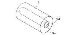
例えば、図10に示すように、フィルムロール9の軸芯9aの部分にIDタグが取り付けられていてもよい。
For example, as shown in FIG. 10, an ID tag may be attached to the portion of the
(G)
上記実施形態では、容器10の開口部10cの近傍にフィルムFの始端F1をミクロ吸盤等の粘着性部材9cによって仮固定した例を挙げて説明した。しかし、本発明はこれに限定されるものではない。
(G)
In the said embodiment, the example which temporarily fixed the start end F1 of the film F to the vicinity of the
例えば、比較的粘着力の小さい両面テープ等を用いることにより、フィルムFの始端F1の仮固定を行ってもよい。 For example, the starting end F1 of the film F may be temporarily fixed by using a double-sided tape or the like having a relatively low adhesive strength.
(H)
上記実施形態では、図4等に示すように、フィルムロール9の幅にあった容器10にフィルムロール9を収納している例を挙げて説明した。しかし、本発明はこれに限定されるものではない。
(H)
In the said embodiment, as shown in FIG. 4 etc., the example which accommodated the
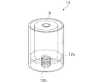
例えば、フィルムロール9の幅と容器の幅方向の長さとが一致しない場合には、図9に示すように、移動側壁部12aをバネ12bの弾性力によってフィルムロール9の幅に合わせて移動させる容器12を用いてもよい。また、バネを用いることなく、フィルムロール9の幅に合わせて移動側壁部12aの位置を固定する構成であってもよい。
For example, when the width of the
(I)
上記実施形態では、フィルムロール9を収納した容器10をそのまま製袋包装機3に装填する例を挙げて説明した。しかし、本発明はこれに限定されるものではない。
(I)
In the said embodiment, the
例えば、図11に示すように、上述した製袋包装機3を複数備えており、さらに搬送装置51、ストック場所52、不良品廃棄場所53および仮受け部60を備えた製袋包装システム(フィルムロールの自動装填システム)50に対しても本発明を適用することができる。この場合でも、納入したフィルムロール9を、人手を介すことなく搬送装置51や仮受け部60等を用いてフィルムロール9の納入から保管、選択、装填までを完全自動化したシステムを構築することができる。
For example, as shown in FIG. 11, a bag making and packaging system (film) including a plurality of the bag making and
(J)
上記実施形態では、フィルムロール9を収納する包装材容器として円筒形の容器10を用いた例を挙げて説明した。しかし、本発明はこれに限定されるものではない。
(J)
In the said embodiment, the example which used the
例えば、直方体形状の容器を用いた場合でも、上記と同様の効果を得ることができるとともに、円筒形と違って転がらないため、運搬時や保管時における操作性を向上させることができる。 For example, even when a rectangular parallelepiped container is used, the same effect as described above can be obtained, and unlike a cylindrical shape, it does not roll, so that operability during transportation and storage can be improved.
(K)
上記実施形態では、容器10の全体(外壁部10aおよび側壁部10b)が、アクリル等の透明樹脂によって形成されている例を挙げて説明した。しかし、本発明はこれに限定されるものではない。
(K)
In the said embodiment, the whole container 10 (
例えば、外壁部10aのみ、あるいは側壁部10bのみが透明樹脂によって形成されていてもよい。この場合でも、内部に収納されたフィルムロール9を確認することができ、フィルムロール9のフィルムFの残量や幅、材質等を外部から容易に確認することができる。
For example, only the
また、容器10の材料としては、透明な樹脂に限定されるものではなく、比較的低発泡(2〜3倍)の発泡材料や再生ペレット樹脂、再生紙から作られるパルプモールド材料等の他の材料を用いて形成されていてもよい。発泡材料を用いた場合には、透明性を維持できないものの、軽量化を図れるという点ではより好ましい。また、再生ペレットやパルプモールド材料についても、透明性は維持できないものの、リサイクル性を向上させるという点でより好ましい。
In addition, the material of the
(L)
上記実施形態では、容器10を構成する一方の側壁部10bから延びる軸芯9aに長尺のフィルムFが巻きつけられてフィルムロール9が構成される例を挙げて説明した。しかし、本発明はこれに限定されるものではない。
(L)
In the said embodiment, the elongate film F was wound around the
例えば、紙管に長尺のフィルムFを巻きつけて構成されるフィルムロールであってもよい。 For example, a film roll configured by winding a long film F around a paper tube may be used.
ただし、上記実施形態のように、容器10の一部としての軸芯9aをフィルムロール9の芯材として用いることで、全てのフィルムFを使い切った後に発生する芯材というゴミが発生しなくなるため、リサイクル性の面で上記実施形態のようにすることがより好ましい。
However, since the
(M)
上記実施形態では、容器10を、フィルムロール9を保護するとともに製袋包装機3に対してフィルムロール9を固定するために使用する例を挙げて説明した。しかし、本発明はこれに限定されるものではない。
(M)
In the said embodiment, the
例えば、図12に示すように、側壁部10bの内側に冷温風ファン等の保温部10iを備えた容器20を用いることもできる。この場合には、外気温度に応じて、長期間保管されるフィルムロール9の温度をほぼ一定の範囲内に保つことができる。この結果、例えば、保管中等において過熱されたフィルムFから成形時に添加された成分等がフィルムFの表面にブリードアウトして、シール不良等の発生が生じることを防止できる。
For example, as shown in FIG. 12, the
本発明の包装材容器は、納入したフィルムロールを包装材容器を開封することなくそのまま包装機に対して装填することができ、納入時から全く人手を介すことなく行われる完全自動装填システムに適した包装材容器を提供することができるとともに、包装材容器をそのまま包装機に取り付けて再利用することでゴミの発生をなくし、収納したフィルムロールの品質を保持したまま包装機に取り付けることができるという効果を奏することから、製袋包装機に用いられるフィルムロール以外にも、食品トレーをラップするためのフィルムロール等の他の用途に用いられるフィルムロールを収納する包装材容器として広く適用可能である。 The packaging material container of the present invention is a fully automatic loading system in which the delivered film roll can be loaded as it is into the packaging machine without opening the packaging material container, and is performed without any manual intervention from the time of delivery. A suitable packaging material container can be provided, and the packaging material container can be attached to the packaging machine as it is to eliminate the generation of dust, and can be attached to the packaging machine while maintaining the quality of the stored film roll. Because it has the effect of being able to be used, it can be widely applied as a packaging material container for storing film rolls used for other purposes such as film rolls for wrapping food trays in addition to film rolls used in bag making and packaging machines. It is.
2 計量機
3 製袋包装機(包装機)
5 製袋包装ユニット
6 フィルム供給ユニット
6a 送出モータ
6b 爪部材
6c 駆動部
9 フィルムロール
9a 軸芯(回転軸)
9b 粘着性部材
9d IDタグ(記憶部)
10 容器(包装材容器)
10a 外壁部
10b 側壁部
10c 開口部
10d 突起部
10e 切欠き部
10f 残量表示パネル(残量表示部)
10g 穴部
10h 回転規制部(回転禁止部材)
11a 連結部
12 容器(包装材容器)
12a 移動側壁部
12b バネ
13 成形機構
15 縦シール機構
17 横シール機構
20 容器(包装材容器)
50 製袋包装システム(フィルムロールの自動交換システム)
51 搬送装置
52 ストック部
53 廃棄場所
55 シールジョー
60 仮受け部
F フィルム
F1 始端
2 Weighing
DESCRIPTION OF
10 Container (packaging material container)
10a
12a Moving
50 Bag making and packaging system (Automatic film roll changing system)
51 Conveying device 52 Stock part 53
Claims (10)
前記フィルムロールの外周を覆う外壁部と、
前記外壁部に形成されており、前記フィルムロールの始端を取り出す開口部と、
前記フィルムロールの中心軸方向の両側を覆うようにそれぞれ設けられており、少なくとも一方において前記フィルムロールの中心軸を回転可能な状態で支持する側壁部と、
前記フィルムロールを装填する包装機に対して取り付けられる固定部と、
を備えている包装材容器。 A packaging material container for storing a film roll,
An outer wall covering the outer periphery of the film roll;
Formed in the outer wall, and an opening for taking out the starting end of the film roll;
Side walls that are provided so as to cover both sides in the central axis direction of the film roll, and support the central axis of the film roll in a rotatable state in at least one of them,
A fixing part attached to a packaging machine for loading the film roll;
A packaging material container.
請求項1に記載の包装材容器。 A rotation prohibiting member that prohibits rotation of the film roll;
The packaging material container according to claim 1.
請求項1または2に記載の包装材容器。 The starting end of the film roll is held in the vicinity of the opening,
The packaging material container according to claim 1.
請求項1から3のいずれか1項に記載の包装材容器。 It further comprises a movable side wall that is movable in the width direction of the film roll.
The packaging material container according to any one of claims 1 to 3.
請求項1から4のいずれか1項に記載の包装材容器。 The fixing part is formed on the side wall part,
The packaging material container of any one of Claim 1 to 4.
請求項1から5のいずれか1項に記載の包装材容器。 The fixing part has a hole part for hooking a claw member formed in the packaging machine.
The packaging material container according to any one of claims 1 to 5.
請求項1から6のいずれか1項に記載の包装材容器。 A storage unit for storing information on the film roll stored therein;
The packaging material container according to any one of claims 1 to 6.
請求項1から7のいずれか1項に記載の包装材容器。 A remaining amount display unit for displaying the remaining amount of the film of the film roll;
The packaging material container according to any one of claims 1 to 7.
請求項1から8のいずれか1項に記載の包装材容器。 At least one of the outer wall portion and the side wall portion is formed of a transparent material,
The packaging material container according to any one of claims 1 to 8.
請求項1から9のいずれか1項に記載の包装材容器。 It further comprises a heat retaining unit for managing the temperature of the film roll.
The packaging material container according to any one of claims 1 to 9.
Priority Applications (2)
| Application Number | Priority Date | Filing Date | Title |
|---|---|---|---|
| JP2005066701A JP4759292B2 (en) | 2005-03-10 | 2005-03-10 | Packaging material container |
| PCT/JP2006/301129 WO2006095499A1 (en) | 2005-03-10 | 2006-01-25 | Packaging material container |
Applications Claiming Priority (1)
| Application Number | Priority Date | Filing Date | Title |
|---|---|---|---|
| JP2005066701A JP4759292B2 (en) | 2005-03-10 | 2005-03-10 | Packaging material container |
Publications (2)
| Publication Number | Publication Date |
|---|---|
| JP2006248564A true JP2006248564A (en) | 2006-09-21 |
| JP4759292B2 JP4759292B2 (en) | 2011-08-31 |
Family
ID=36953103
Family Applications (1)
| Application Number | Title | Priority Date | Filing Date |
|---|---|---|---|
| JP2005066701A Expired - Fee Related JP4759292B2 (en) | 2005-03-10 | 2005-03-10 | Packaging material container |
Country Status (2)
| Country | Link |
|---|---|
| JP (1) | JP4759292B2 (en) |
| WO (1) | WO2006095499A1 (en) |
Cited By (5)
| Publication number | Priority date | Publication date | Assignee | Title |
|---|---|---|---|---|
| WO2011055781A1 (en) * | 2009-11-05 | 2011-05-12 | 株式会社ニコン | Substrate cartridge, substrate processing apparatus, substrate processing system, substrate processing method, control apparatus, and method for manufacturing display element |
| JP2011098809A (en) * | 2009-11-05 | 2011-05-19 | Nikon Corp | Substrate cartridge, substrate processing device, substrate processing system, substrate processing method, control device and method of manufacturing display element |
| JP2011098808A (en) * | 2009-11-05 | 2011-05-19 | Nikon Corp | Substrate cartridge, substrate processing device, substrate processing system, substrate processing method, control device and method of manufacturing display element |
| KR101248886B1 (en) | 2011-04-13 | 2013-04-01 | 주식회사 유라코퍼레이션 | Adhesive tape supporting apparatus |
| JP2022072824A (en) * | 2020-10-30 | 2022-05-17 | 藤森工業株式会社 | Management system and method of control |
Citations (2)
| Publication number | Priority date | Publication date | Assignee | Title |
|---|---|---|---|---|
| JPS6159534A (en) * | 1984-08-30 | 1986-03-27 | Nec Corp | Stack pointer |
| JP2003160110A (en) * | 2001-11-21 | 2003-06-03 | Takazono Sangyo Co Ltd | Cartridge type portion-packaging paper |
Family Cites Families (2)
| Publication number | Priority date | Publication date | Assignee | Title |
|---|---|---|---|---|
| JPH0142521Y2 (en) * | 1984-09-26 | 1989-12-12 | ||
| US5364042A (en) * | 1993-01-05 | 1994-11-15 | Minnesota Mining And Manufacturing Company | Spool adapter |
-
2005
- 2005-03-10 JP JP2005066701A patent/JP4759292B2/en not_active Expired - Fee Related
-
2006
- 2006-01-25 WO PCT/JP2006/301129 patent/WO2006095499A1/en not_active Ceased
Patent Citations (2)
| Publication number | Priority date | Publication date | Assignee | Title |
|---|---|---|---|---|
| JPS6159534A (en) * | 1984-08-30 | 1986-03-27 | Nec Corp | Stack pointer |
| JP2003160110A (en) * | 2001-11-21 | 2003-06-03 | Takazono Sangyo Co Ltd | Cartridge type portion-packaging paper |
Cited By (6)
| Publication number | Priority date | Publication date | Assignee | Title |
|---|---|---|---|---|
| WO2011055781A1 (en) * | 2009-11-05 | 2011-05-12 | 株式会社ニコン | Substrate cartridge, substrate processing apparatus, substrate processing system, substrate processing method, control apparatus, and method for manufacturing display element |
| JP2011098809A (en) * | 2009-11-05 | 2011-05-19 | Nikon Corp | Substrate cartridge, substrate processing device, substrate processing system, substrate processing method, control device and method of manufacturing display element |
| JP2011098808A (en) * | 2009-11-05 | 2011-05-19 | Nikon Corp | Substrate cartridge, substrate processing device, substrate processing system, substrate processing method, control device and method of manufacturing display element |
| KR101248886B1 (en) | 2011-04-13 | 2013-04-01 | 주식회사 유라코퍼레이션 | Adhesive tape supporting apparatus |
| JP2022072824A (en) * | 2020-10-30 | 2022-05-17 | 藤森工業株式会社 | Management system and method of control |
| JP7794559B2 (en) | 2020-10-30 | 2026-01-06 | Zacros株式会社 | Management system and control method |
Also Published As
| Publication number | Publication date |
|---|---|
| WO2006095499A1 (en) | 2006-09-14 |
| JP4759292B2 (en) | 2011-08-31 |
Similar Documents
| Publication | Publication Date | Title |
|---|---|---|
| US11814207B2 (en) | Automated packaging station and system for packaging objects | |
| HK1039305B (en) | Customized prescription product packaging and method and system for producing customized prescription product packaging | |
| KR20040049825A (en) | Automated pack out | |
| JP6477478B2 (en) | Drug cassette and drug packaging device | |
| JP4759292B2 (en) | Packaging material container | |
| US7389625B2 (en) | Packaging apparatus and packaging system including the same | |
| US10822127B2 (en) | Packaging apparatus | |
| KR101628709B1 (en) | automatic measuring packaging machine using multi head | |
| JP2017047947A (en) | Label issuing device | |
| CN218907717U (en) | Packing apparatus and vending machine with the same | |
| JP2017222394A (en) | Label printing system for attaching label to egg, egg shipment management system including the same, and egg shipment management method | |
| US20190060050A1 (en) | Clean release split carton and method | |
| JP2011120847A (en) | Medicine packaging apparatus | |
| US11414222B2 (en) | Automated system for the integration of a liner and envelope | |
| CN104338726A (en) | Work cabinet and sheet | |
| JP4440791B2 (en) | Automatic film roll change system | |
| JP2006117324A (en) | Film packaging machine | |
| JP2023079241A (en) | Mounting paper body with shrink film for packaging, packaging box formed using the same, automatic packing device for forming packaging container body, and automatic packing method for forming delivery box body using the same | |
| KR101022327B1 (en) | Air packing hundred formation | |
| JP4860683B2 (en) | Sealing device for packaging containers | |
| JPH11152106A (en) | Automatic packaging apparatus | |
| CN103619709A (en) | Drug packaging device | |
| JP7348624B2 (en) | Packaging equipment, packaging method | |
| KR20200103515A (en) | Internal packaging for boxes | |
| JP5974530B2 (en) | Packaging equipment |
Legal Events
| Date | Code | Title | Description |
|---|---|---|---|
| A621 | Written request for application examination |
Free format text: JAPANESE INTERMEDIATE CODE: A621 Effective date: 20080305 |
|
| A131 | Notification of reasons for refusal |
Free format text: JAPANESE INTERMEDIATE CODE: A131 Effective date: 20110208 |
|
| A521 | Written amendment |
Free format text: JAPANESE INTERMEDIATE CODE: A523 Effective date: 20110330 |
|
| RD02 | Notification of acceptance of power of attorney |
Free format text: JAPANESE INTERMEDIATE CODE: A7422 Effective date: 20110330 |
|
| TRDD | Decision of grant or rejection written | ||
| A01 | Written decision to grant a patent or to grant a registration (utility model) |
Free format text: JAPANESE INTERMEDIATE CODE: A01 Effective date: 20110531 |
|
| A01 | Written decision to grant a patent or to grant a registration (utility model) |
Free format text: JAPANESE INTERMEDIATE CODE: A01 |
|
| A61 | First payment of annual fees (during grant procedure) |
Free format text: JAPANESE INTERMEDIATE CODE: A61 Effective date: 20110606 |
|
| R150 | Certificate of patent (=grant) or registration of utility model |
Free format text: JAPANESE INTERMEDIATE CODE: R150 |
|
| FPAY | Renewal fee payment (prs date is renewal date of database) |
Free format text: PAYMENT UNTIL: 20140610 Year of fee payment: 3 |
|
| R250 | Receipt of annual fees |
Free format text: JAPANESE INTERMEDIATE CODE: R250 |
|
| LAPS | Cancellation because of no payment of annual fees |