JP6477478B2 - Drug cassette and drug packaging device - Google Patents
Drug cassette and drug packaging device Download PDFInfo
- Publication number
- JP6477478B2 JP6477478B2 JP2015537929A JP2015537929A JP6477478B2 JP 6477478 B2 JP6477478 B2 JP 6477478B2 JP 2015537929 A JP2015537929 A JP 2015537929A JP 2015537929 A JP2015537929 A JP 2015537929A JP 6477478 B2 JP6477478 B2 JP 6477478B2
- Authority
- JP
- Japan
- Prior art keywords
- medicine
- rotating body
- cassette
- rotating
- shaft
- Prior art date
- Legal status (The legal status is an assumption and is not a legal conclusion. Google has not performed a legal analysis and makes no representation as to the accuracy of the status listed.)
- Active
Links
- 239000003814 drug Substances 0.000 title claims description 183
- 229940079593 drug Drugs 0.000 title claims description 27
- 238000009512 pharmaceutical packaging Methods 0.000 title 1
- 238000004806 packaging method and process Methods 0.000 claims description 26
- 230000001105 regulatory effect Effects 0.000 claims description 23
- 230000002093 peripheral effect Effects 0.000 claims description 18
- 238000007599 discharging Methods 0.000 claims description 2
- 239000003795 chemical substances by application Substances 0.000 description 22
- 239000000126 substance Substances 0.000 description 22
- 239000003990 capacitor Substances 0.000 description 5
- 238000001514 detection method Methods 0.000 description 5
- 210000000078 claw Anatomy 0.000 description 4
- 238000012858 packaging process Methods 0.000 description 3
- 230000003287 optical effect Effects 0.000 description 2
- 239000002775 capsule Substances 0.000 description 1
- 238000004140 cleaning Methods 0.000 description 1
- 238000011109 contamination Methods 0.000 description 1
- 238000006073 displacement reaction Methods 0.000 description 1
- 230000005484 gravity Effects 0.000 description 1
- 239000000463 material Substances 0.000 description 1
- 238000000034 method Methods 0.000 description 1
- 238000012986 modification Methods 0.000 description 1
- 230000004048 modification Effects 0.000 description 1
- 238000012856 packing Methods 0.000 description 1
- 239000000843 powder Substances 0.000 description 1
- 238000003825 pressing Methods 0.000 description 1
- 230000001681 protective effect Effects 0.000 description 1
- 229920003002 synthetic resin Polymers 0.000 description 1
- 239000000057 synthetic resin Substances 0.000 description 1
Images


Classifications
-
- B—PERFORMING OPERATIONS; TRANSPORTING
- B65—CONVEYING; PACKING; STORING; HANDLING THIN OR FILAMENTARY MATERIAL
- B65B—MACHINES, APPARATUS OR DEVICES FOR, OR METHODS OF, PACKAGING ARTICLES OR MATERIALS; UNPACKING
- B65B1/00—Packaging fluent solid material, e.g. powders, granular or loose fibrous material, loose masses of small articles, in individual containers or receptacles, e.g. bags, sacks, boxes, cartons, cans, or jars
- B65B1/04—Methods of, or means for, filling the material into the containers or receptacles
- B65B1/10—Methods of, or means for, filling the material into the containers or receptacles by rotary feeders
-
- A—HUMAN NECESSITIES
- A61—MEDICAL OR VETERINARY SCIENCE; HYGIENE
- A61J—CONTAINERS SPECIALLY ADAPTED FOR MEDICAL OR PHARMACEUTICAL PURPOSES; DEVICES OR METHODS SPECIALLY ADAPTED FOR BRINGING PHARMACEUTICAL PRODUCTS INTO PARTICULAR PHYSICAL OR ADMINISTERING FORMS; DEVICES FOR ADMINISTERING FOOD OR MEDICINES ORALLY; BABY COMFORTERS; DEVICES FOR RECEIVING SPITTLE
- A61J7/00—Devices for administering medicines orally, e.g. spoons; Pill counting devices; Arrangements for time indication or reminder for taking medicine
- A61J7/0076—Medicament distribution means
-
- A—HUMAN NECESSITIES
- A61—MEDICAL OR VETERINARY SCIENCE; HYGIENE
- A61J—CONTAINERS SPECIALLY ADAPTED FOR MEDICAL OR PHARMACEUTICAL PURPOSES; DEVICES OR METHODS SPECIALLY ADAPTED FOR BRINGING PHARMACEUTICAL PRODUCTS INTO PARTICULAR PHYSICAL OR ADMINISTERING FORMS; DEVICES FOR ADMINISTERING FOOD OR MEDICINES ORALLY; BABY COMFORTERS; DEVICES FOR RECEIVING SPITTLE
- A61J7/00—Devices for administering medicines orally, e.g. spoons; Pill counting devices; Arrangements for time indication or reminder for taking medicine
- A61J7/04—Arrangements for time indication or reminder for taking medicine, e.g. programmed dispensers
- A61J7/0409—Arrangements for time indication or reminder for taking medicine, e.g. programmed dispensers with timers
-
- B—PERFORMING OPERATIONS; TRANSPORTING
- B65—CONVEYING; PACKING; STORING; HANDLING THIN OR FILAMENTARY MATERIAL
- B65B—MACHINES, APPARATUS OR DEVICES FOR, OR METHODS OF, PACKAGING ARTICLES OR MATERIALS; UNPACKING
- B65B57/00—Automatic control, checking, warning, or safety devices
- B65B57/10—Automatic control, checking, warning, or safety devices responsive to absence, presence, abnormal feed, or misplacement of articles or materials to be packaged
- B65B57/14—Automatic control, checking, warning, or safety devices responsive to absence, presence, abnormal feed, or misplacement of articles or materials to be packaged and operating to control, or stop, the feed of articles or material to be packaged
-
- G—PHYSICS
- G07—CHECKING-DEVICES
- G07F—COIN-FREED OR LIKE APPARATUS
- G07F17/00—Coin-freed apparatus for hiring articles; Coin-freed facilities or services
- G07F17/0092—Coin-freed apparatus for hiring articles; Coin-freed facilities or services for assembling and dispensing of pharmaceutical articles
Description
本発明は、薬剤カセット及び薬剤包装装置に関するものである。 The present invention relates to a medicine cassette and a medicine packaging apparatus.
従来、小物(物品)を整列して供給するための装置として、例えば、第1駆動手段によって回転される円板状の第1回転体と、第2駆動手段によって回転される円環状の第2回転体とを備えたものが公知である(例えば、特許文献1参照)。 Conventionally, as an apparatus for aligning and supplying small articles (articles), for example, a disk-shaped first rotating body rotated by first driving means and an annular second rotating by second driving means. The thing provided with the rotary body is well-known (for example, refer patent document 1).
しかしながら、前記従来の装置を単純に薬剤カセットの機構として採用しようとしても、円板の駆動機構等の構成部品をどのようにレイアウトするのか等の問題があり、コンパクトに構成することは難しい。 However, even if the conventional device is simply adopted as the mechanism of the medicine cassette, there are problems such as how to lay out the components such as the disk drive mechanism, and it is difficult to make it compact.
本発明は、第1回転体及び第2回転体によって薬剤を1つずつ払い出すことができる、コンパクトな構成の薬剤カセット及び薬剤包装装置を提供することを課題とする。 This invention makes it a subject to provide the chemical | medical agent cassette and chemical | medical agent packaging apparatus of a compact structure which can pay out the chemical | medical agent one by one with a 1st rotary body and a 2nd rotary body.
本発明は、前記課題を解決するための手段として、
筒状体と、
前記筒状体の内周面とで薬剤を収容可能な薬剤収容部を構成する底面となる上面を有し、第1回転軸を中心として回転可能な第1回転体と、
前記筒状体の開口部外周に配置され、第2回転軸を中心として回転可能な第2回転体と、
前記第2回転体の回転により外部に排出される薬剤を検出する薬剤検出手段と、
前記第1回転体及び前記第2回転体を回転させているにも拘わらず、前記薬剤検出手段により薬剤が検出されないとき、前記第1回転体を一時的に逆回転させる制御手段と、
を備え、
前記第1回転体と前記第2回転体とは、前記第1回転軸と前記第2回転軸とが互いに傾斜するように配置され、前記第1回転体の外周縁の一部が前記第2回転体の内周縁の一部に徐々に接近するように配置され、
前記筒状体の外側に、少なくとも、前記第1回転体と前記第2回転体をそれぞれ回転駆動させる第1駆動軸と第2駆動軸を配置したことを特徴とする薬剤カセットを提供する。
As a means for solving the above problems, the present invention provides:
A tubular body;
Have a top surface serving as a bottom surface constituting the medicine accommodating portion capable of containing the drug in the inner peripheral surface of the cylindrical body, a first rotor rotatable about a first rotation axis,
A second rotating body disposed on the outer periphery of the opening of the cylindrical body and rotatable about a second rotation axis;
A medicine detecting means for detecting a medicine discharged to the outside by the rotation of the second rotating body;
Control means for temporarily reversely rotating the first rotating body when no medicine is detected by the medicine detecting means despite rotating the first rotating body and the second rotating body;
With
The first rotating body and the second rotating body are disposed such that the first rotating shaft and the second rotating shaft are inclined with respect to each other, and a part of an outer peripheral edge of the first rotating body is the second rotating body. It is arranged to gradually approach a part of the inner periphery of the rotating body,
Provided is a medicine cassette characterized in that at least a first drive shaft and a second drive shaft for rotating and driving the first rotating body and the second rotating body, respectively, are arranged outside the cylindrical body.
前記第2回転体によって搬送される薬剤の高さを規制する昇降可能な高さ規制部を備え、
前記高さ規制部を移動させる駆動力を第1モータから得て、前記高さ規制部に伝達する軸を、前記筒状体の外側に配置するのが好ましい。
A height restricting portion capable of moving up and down to restrict the height of the medicine conveyed by the second rotating body;
It is preferable that a driving force for moving the height restricting portion is obtained from the first motor, and a shaft for transmitting the driving force to the height restricting portion is disposed outside the cylindrical body .
前記第2回転体によって搬送される薬剤の幅を規制する幅規制体を備え、
前記幅規制体を移動させる駆動力を第2モータから得て、幅規制体に伝達する第1軸部材を、前記筒状体の外側に配置するのが好ましい。
A width regulating body for regulating the width of the medicine conveyed by the second rotating body;
It is preferable that the first shaft member that obtains the driving force for moving the width restricting body from the second motor and transmits the driving force to the width restricting body is disposed outside the cylindrical body .
前記第2回転体によって搬送される薬剤を排出するホッパーを備え、
前記ホッパーを、前記筒状体の外側に配置するのが好ましい。
A hopper for discharging the medicine conveyed by the second rotating body;
It is preferable that the hopper is disposed outside the cylindrical body .
本発明は、前記課題を解決するための手段として、
筒状体と、前記筒状体とで薬剤を収容可能な薬剤収容部を構成し、第1回転軸を中心として回転可能な第1回転体と、前記筒状体の開口部外周に配置され、第2回転軸を中心として回転可能な第2回転体と、前記第2回転体の回転により外部に排出される薬剤を検出する薬剤検出手段と、前記第1回転体及び前記第2回転体を回転させているにも拘わらず、前記薬剤検出手段により薬剤が検出されないとき、前記第1回転体を一時的に逆回転させる制御手段とを備え、前記筒状体の外側に、少なくとも、前記第1回転体と前記第2回転体をそれぞれ回転駆動させる第1駆動軸と第2駆動軸を配置した薬剤カセットと、
前記薬剤カセットを着脱可能な支持ベースと、
前記薬剤カセットから払い出された薬剤を包装する包装部と、を備え、
前記薬剤カセットは、
前記第2回転体によって搬送される薬剤の高さを規制する昇降可能な高さ規制部と、
前記第2回転体によって搬送される薬剤の幅を規制する幅規制体と、を備え、
前記第1回転体、前記第2回転体、前記高さ規制部、前記幅規制体を駆動する動力を発生させるモータが前記支持ベースに設けられていることを特徴とする薬剤包装装置を提供する。
As a means for solving the above problems, the present invention provides:
The cylindrical body and the cylindrical body constitute a drug container that can store a drug, and are disposed on the outer periphery of the opening of the cylindrical body, the first rotating body that can rotate about the first rotation axis. A second rotating body rotatable about the second rotation axis, a medicine detecting means for detecting medicine discharged to the outside by the rotation of the second rotating body, the first rotating body and the second rotating body Control means for temporarily reversely rotating the first rotating body when no medicine is detected by the medicine detecting means despite the rotation of the medicine detecting means, and at least outside the cylindrical body, A medicine cassette in which a first drive shaft and a second drive shaft for rotating and driving the first rotating body and the second rotating body, respectively,
A support base to which the medicine cassette is detachable;
A packaging unit for packaging the medicine dispensed from the medicine cassette,
The drug cassette is
A height restricting portion capable of moving up and down to restrict the height of the medicine conveyed by the second rotating body;
A width regulating body for regulating the width of the medicine conveyed by the second rotating body,
Provided is a medicine packaging device, wherein the support base is provided with a motor for generating power for driving the first rotating body, the second rotating body, the height regulating portion, and the width regulating body. .
以下、本発明に係る実施形態を添付図面に従って説明する。なお、以下の説明では、必要に応じて特定の方向や位置を示す用語(例えば、「上」、「下」、「側」、「端」を含む用語)を用いるが、それらの用語の使用は図面を参照した発明の理解を容易にするためであって、それらの用語の意味によって本発明の技術的範囲が限定されるものではない。また、以下の説明は、本質的に例示に過ぎず、本発明、その適用物、あるいは、その用途を制限することを意図するものではない。 Embodiments according to the present invention will be described below with reference to the accompanying drawings. In the following description, terms indicating specific directions and positions (for example, terms including “up”, “down”, “side”, “end”) are used as necessary. Is for facilitating understanding of the invention with reference to the drawings, and the technical scope of the present invention is not limited by the meaning of these terms. Further, the following description is merely illustrative in nature and is not intended to limit the present invention, its application, or its use.
図1は、本実施形態に係る薬剤包装装置の概略図である。この薬剤包装装置は、包装装置本体1に、上方側から順に、複数の第1薬剤フィーダ2、複数の第2薬剤フィーダ3、手撒き薬剤供給部4、及び、包装部5をそれぞれ設けたもので、これらは制御装置6によって駆動制御されるようになっている。
FIG. 1 is a schematic view of a medicine packaging apparatus according to this embodiment. In this medicine packaging apparatus, a plurality of first medicine feeders 2, a plurality of
第1薬剤フィーダ2は、従来公知のもので、上下左右に複数個が配置されている。各第1薬剤フィーダ2には、種類別に多数の薬剤(以下、薬剤と記載する場合、主に、錠剤であるが、カプセル剤等も含まれるものとする。)が収容されている。処方箋データ等に基づいて、該当する第1薬剤フィーダ2から所定数の薬剤が排出されるようになっている。 The first medicine feeder 2 is a conventionally known one, and a plurality of first medicine feeders 2 are arranged vertically and horizontally. Each first drug feeder 2 contains a large number of drugs (hereinafter referred to as drugs, mainly tablets, but also capsules etc.) by type. A predetermined number of medicines are discharged from the corresponding first medicine feeder 2 based on prescription data and the like.
第2薬剤フィーダ3は、使用頻度の低い薬剤や、数量をカウントする必要のある薬剤等を収容して使用する。詳細については後述する。
The
手撒き薬剤供給部4は、格子状に形成された各領域に、半錠の錠剤や使用頻度の低い薬剤を手撒きでセットしておき、包装部5で包装する際に利用するためのものである。
The hand-made
包装部5は、ロールに巻回した包装紙を巻き戻して供給し、前記各薬剤フィーダや手撒き薬剤供給部4から供給される薬剤を1包分ずつ包装する。
The
以下、本発明の特徴部分である第2薬剤フィーダ3について詳述する。
第2薬剤フィーダ3は、包装装置本体1の前面に、上下2列で左右方向に4つずつ並設され、図2及び図3に示すように、支持ベース7と、各支持ベース7に着脱可能な薬剤カセット8とからなる。Hereinafter, the 2nd chemical |
The
図4に示すように、支持ベース7は、ベース本体9と、そこに装着される複数のモータ等の構成部品と、ベースカバー10とを備える。
図4及び図5に示すように、ベース本体9は、合成樹脂材料からなる平板状のもので、前方側及び中央部にはRFIDリーダ11が取り付けられている。RFIDリーダ11は、薬剤カセット側に設けたRFID(Radio Frequency IDentification)を読み取って、その薬剤カセット8と、収容される薬剤の種別等の情報を取得する。また、ベース本体9の両側には、第1モータ12、第2モータ13、及び、カセットロック部14が取り付けられている。As shown in FIG. 4, the
As shown in FIGS. 4 and 5, the
第1モータ12は、先端部分がベース本体9の前方一端側の角部に固定した第1支持片15に固定されている。第1支持片15は、対向する上面部及び下面部と、それらを接続する垂直面部とを備え、第1モータ12の回転軸は垂直面部を貫通し、その先端部分には第1かさ歯車16が固定されている。また、第1支持片15の上下面部間には第1回転軸17が回転可能に支持されている。第1回転軸17の中間部分には前記第1かさ歯車16が噛合する第2かさ歯車18が固定され、上方部分には、後述する薬剤カセット8側に設けた高さ規制体69の平歯車70a(図6参照)と噛合する第1平歯車19が固定されている。
The
第2モータ13は、前記第1モータ12と同様に、先端部分がベース本体9の前方他端側の角部に固定した、前記第1支持片15と同様な構成の第2支持片20に固定されている。第2モータ13の回転軸の先端には第3かさ歯車21が固定されている。第2支持片20の上下面部間には第2回転軸22が回転可能に支持されている。第2回転軸22の中間部分には前記第3かさ歯車21が噛合する第4かさ歯車23が固定され、上方部分には、後述する薬剤カセット8側に設けた幅規制体71の平歯車72b(図6参照)に噛合する第2平歯車24が固定されている。
Similar to the
カセットロック部14は、支持ベース7に装着された第2薬剤カセット8を脱落不能にロックするためのものである。カセットロック部14は、支持ベース7に固定される取付片25に、作動片26と、この作動片26を駆動するためのソレノイド27とが取り付けられている。作動片26は、その軸部を取付片25の対向面間に回転可能に支持され、一端側には突片28が移動可能に取り付けられている。突片28は、取付片25との間に配置したスプリング(図示せず)によって上方に付勢されている。また、作動片26の他端部は、ソレノイド27のロッド先端に回転可能に連結されている。これにより、ソレノイド27を励磁して駆動させると、作動片26が回動して突片28が昇降して底面部41の上面から出没し、後述する薬剤カセット8の底面に形成した係止凹部(図示せず)に係脱する。
The
また、ベース本体9の後方側には、垂直上方に延びる取付板29が固定されている。取付板29には、第3モータ30、第4モータ31及び充電部32が取り付けられている。
A mounting
第3モータ30は、先端側を取付板29の下方側に固定され、そこから突出する回転軸の先端部分に第1プーリ33が固定されている。取付板29の上方側には、一端に第2プーリ34を固定され、他端に第1駆動ギア35を固定された回転軸が回転可能に支持されている。第1プーリ33と第2プーリ34とには第1ベルト36が掛け渡され、第3モータ30の駆動力が第1駆動ギア35に伝達されるようになっている。第1駆動ギア35は、後述する薬剤カセット側に設けた第1従動ギア61に噛合し、第1回転体51を正逆回転させることができるようになっている。
The
第4モータ31は、前記第3モータ30と同様に、先端側を取付板29の下方側に固定され、そこから突出する回転軸の先端部分に第3プーリ37が固定されている。取付板29の上方側には、一端に第4プーリ38を固定され、他端に第2駆動ギア39を固定された回転軸が回転可能に支持されている。第3プーリ37と第4プーリ38とには第2ベルト40が掛け渡され、第4モータ31の駆動力が第2駆動ギア39に伝達されるようになっている。第2駆動ギア39は、後述する薬剤カセット側に設けた第2従動ギア64に噛合し、第2回転体52を正逆回転させることができるようになっている。
As with the
充電部32は、薬剤カセット8が支持ベース7に装着されることにより、薬剤カセット8側に電力を供給可能とする端子等で構成されている(例えば、薬剤カセット8側又は支持ベース7側の充電部32のいずれか一方が雄型の端子、残る他方が雌型の端子で構成すればよい。)。これにより、薬剤カセット8が支持ベース7に装着されると充電部32を介して、後述する薬剤カセット8側の電池(又はコンデンサ)に電力を供給して充電することができるようになっている。
The charging
図4に示すように、ベースカバー10は、底面部41と背面部42とで構成されている。底面部41には、両側に前後方向に延びるガイド部43が形成されている。ガイド部43の内側面によって後述する薬剤カセット8のカセット底面部54がガイドされる。ガイド部43の上面外側縁からはさらに上方に突出する補助壁44が形成されている。補助壁44からは内側にガイド受片45が突出し、薬剤カセット8のカセット底面部54に形成したガイド片58がガイドされるようになっている。図3(a)に示すように、右側のガイド部43の前端面からは、前記第1平歯車19の一部が露出し、左側のガイド部43の前端面からは、前記第2平歯車24の一部が露出している。また、底面部41の前端中央には、薬剤カセット8の前端部分の把持を容易にするための窪み部46が形成されている。さらに、底面部41の上面には、窪み部46の近傍部分にスリット状の開口が形成され、そこから前記カセットロック部14の突片28が出没可能となっている。
As shown in FIG. 4, the
背面部42から、前記第1駆動ギア35及び前記第2駆動ギア39の先端部分(ギア部分)が露出している。また、背面部42には、薬剤カセット8から払い出された薬剤を案内するホッパー47が取り付けられている。但し、このホッパー47は、薬剤カセット8に固定されていてもよい。そして、ホッパー47に排出される薬剤は、排出センサ48によって検出されてカウントされる。
From the
排出センサ48には光センサが使用され、図3(b)に示すように、第2回転体52の上面よりも所定寸法(例えば、1mm)下方側に光路が設定されている。すなわち、薬剤の重心位置が第2回転体52の上面から落下する位置まで移動することにより、薬剤が傾いた位置を検出することができるようになっている。これにより、薬剤数をカウントする場合、最終の薬剤の排出が確実となった時点で第2回転体52の回転を停止させることができるので、次の薬剤の排出を確実に防止することが可能となる。
An optical sensor is used as the
図6に示すように、薬剤カセット8は、カセット本体49内に筒状体50を収容し、この筒状体50の下端開口部に第1回転体51を配置し、さらに筒状体50の上端開口部外周に第2回転体52を配置したもので、カセット本体49の上方開口部は蓋体53(図3参照)によって閉鎖されている。
As shown in FIG. 6, the
カセット本体49は、カセット底面部54、カセット前端部55、及び、カセット胴部56を備える。
The
カセット底面部54は、両側部が上方に向かって延在し、支持ベース7のガイド部43によってガイドされる側面部57を構成している。また、側面部57の上縁には、さらに側方に向かって延在し、その側縁部にはガイド片58が形成されている。ガイド片58は、支持ベース7のベースカバー10に形成したガイド受片45によって上方への移動が規制される。カセット底面部54の底面中央部右寄りには、斜めに突出する筒状の軸受部59が形成されている。軸受部59には回転軸51aが回転可能に支持される。
The cassette
図7に示すように、カセット底面部54の前端部分は上方に向かって延在し、表示パネル60を取付可能となっている。ここでは、表示パネル60には電子ペーパーが使用されている。ここで、電子ペーパーとは、表示内容の書き換えで電力が必要となるものの、表示状態での電力消費がないものである。そして、電子ペーパーには、処方データに基づいて、その薬剤カセット8内に収容すべき薬剤の名称や数量、場合によっては患者名等を含む種々の表示データが入力されて表示されるようになっている。これにより、ユーザは、一目で薬剤カセット8内に収容された薬剤を把握することができる。しかも、薬剤の名称や数量を書き換え可能に表示することで、薬剤の変更等にも柔軟に対応することが可能である。また、薬剤を充填する場合でも、電子ペーパーに表示された内容を確認してから作業を進めることができる。
As shown in FIG. 7, the front end portion of the cassette
ところで、電子ペーパーは、表示データが入力されても、表示の書き換えに多少の時間がかかる。そこで、図示しない充電式の電池(又はコンデンサ)を設け、薬剤カセット8を支持ベース7に装着している際に、この電池(又はコンデンサ)に充電しておく。そして、電子ペーパーに対して信号が入力されてから直ぐに支持ベース7から薬剤カセット8が取り外されたとしても、電池(又はコンデンサ)から電子ペーパーに電力を供給して表示内容を書き換えることができるようにしている。なお、表示データの入力開始から完了までに要する所定時間で、カセットロック部14を作動させてロック状態を解除することにより支持ベース7から薬剤カセット8を取り外すことができるようにしている。この場合のロック解除までの時間は、予め装置本体1側の記憶手段(図示せず)に記憶させておけばよい。
By the way, electronic paper takes some time to rewrite the display even if display data is input. Therefore, a rechargeable battery (or capacitor) (not shown) is provided, and the battery (or capacitor) is charged when the
このように、前記構成の薬剤カセット8によれば、電子ペーパーを使用しているにも拘わらず、表示データの入力が行われれば、即座に支持ベース7から取り外して、薬剤の充填作業等を行うことができる。取り外した状態では、電子ペーパーでの消費電力は0であるので、電池(又はコンデンサ)であっても、問題なく所望の表示データを表示させることができる。そして、表示された内容に従って、該当する薬剤を充填する等の作業を進めることが可能である。
As described above, according to the
図6に示すように、カセット底面部54の背面側には、一端に第1従動ギア61が固定され、他端に第3駆動ギア62が固定された第1回転軸63と、一端に第2従動ギア64が固定され、他端に第4駆動ギア65(ハイポイドギア)が固定された第2回転軸66とがそれぞれ回転可能に支持されている。なお、カセット底面部54の上面は、略C字形をしたカバー体(図示せず)で覆われている。
As shown in FIG. 6, on the back side of the cassette
カセット前端部55は、薬剤カセット8の前端両側角部を構成する第1収容凹部67と第2収容凹部68とを連結したもので、カセット底面部54に固定されている。第1収容凹部67には、高さ規制体69を駆動するためのネジ軸70が回転可能に支持されている。第2収容凹部68には、幅規制体71を駆動するための第1軸部材72が配置されている。
The cassette
図8及び図9に示すように、高さ規制体69は、筒部73と、この筒部73から延在する高さ規制部74とを備える。筒部73には、ネジ軸70の外周面に形成した雄ねじが螺合する雌ねじを形成され、カセット前端部55の第1収容凹部67内に配置される。高さ規制部74は、第2回転体52の上面に対して所望の間隔で配置される第1ガイド面75と、第2回転体52による周方向の薬剤搬送経路の外周面の一部を構成する第2ガイド面76とを有する。ネジ軸70の下端部には平歯車70aが一体化され、支持ベース7側の第1平歯車19が噛合している。これにより、第1モータ12からの駆動力がネジ軸70に伝達され、その雄ねじと筒部73の雌ねじとの螺合位置が変化して高さ規制体69が昇降する。そして、第2回転体52の上面に対する第1ガイド面75の位置が調整される。この結果、第2回転体52によって周方向に搬送される薬剤が、高さ規制体69によって高さを規制される。また、高さ規制部74の上面には、支軸を中心として回動可能に補助片77が取り付けられている。補助片77は、支軸に設けたスプリング(図示せず)によって高さ規制部74の上面から起き上がるように付勢されている。これにより、高さ規制体69が降下すれば、スプリングの付勢力によって補助片77が起き上がり、高さ規制部74の上面と蓋体53の下面との間に生じる隙間を覆って薬剤の進入を阻止することができるようになっている。
As shown in FIGS. 8 and 9, the
図10に示すように、幅規制体71は、第2回転体52の外周に沿って徐々に外径側へと湾曲した第1ガイド面78と、これに続く平坦な第2ガイド面79とを有する。第1ガイド面78の外径側には、前記第1軸部材72の上端部に設けた駆動ギア72aが噛合する従動ギア80aを一端部に設けた第2軸部材80が配置されている。第2軸部材80の他端側には、幅規制体71に一体化される雌ねじ部材71aの雌ねじに螺合する雄ねじが形成されている。そして、第1軸部材72が正逆回転すると、駆動ギア72a及び従動ギア80aを介して第2軸部材80が回転し、雌ねじ部材71aを介して幅規制体71が、図10(a)に示す幅広位置と、図10(b)に示す幅狭位置との間で往復移動する。なお、幅規制体71の上面は、駆動ギア72a及び従動ギア80aと共に保護カバー(図示せず)によって覆われている。
As shown in FIG. 10, the
図6に示すように、カセット胴部56は、矩形枠体形状で、前端側がカセット前端部55の各収容凹部67、68とで収容部をそれぞれ形成する。また、カセット胴部56の内周側には、第2回転体52の外周縁に沿う内周面の一部(約半分)を構成する内壁56aが形成されている。内壁56aの一端部には、排出ガイド片81(図10参照)が取り付けられ、第2回転体52によって搬送された薬剤をホッパー47へと導く。
As shown in FIG. 6, the
筒状体50は、第2回転体52の内周縁に沿った上端開口部を有し、下方側に向かって延びている。筒状体50の下端開口部は、第1回転体51の傾斜角度に合わせて斜めにカットされている。筒状体50の内周面と第1回転体51の上面とで、薬剤を収容可能な薬剤収容部82(図8参照)が形成されている。
The
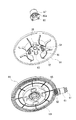
図11及び図12に示すように、第1回転体51は、円板状で、上面部83と下面部84とで構成されている。そして、第1回転体51は、筒状体50の下端開口部に配置され、水平面に対して傾斜している。
As shown in FIGS. 11 and 12, the first
上面部83の上面には、中心に上方筒部85が形成され、その上方筒部85の周囲4箇所には貫通孔86が形成されている。上方筒部85はキャップ87によって覆われる。キャップ87には、下端開口部からは4箇所等分で脚部88が形成されている。脚部88は前記各貫通孔86に挿通され、その先端に形成した爪部88aが、後述する係止片100の係止爪に係止される。貫通孔86の周囲には、貫通孔86の近傍部分から外径側に向かって延びる複数の突条89が形成されている。各突条89は、第1回転体51の回転中心から半径方向に延びる直線に対して第1回転体51の回転方向とは反対側へと傾斜している。また、各突条89は、上面部83の上面から突出する第1傾斜面90と、前記回転方向に向かうに従って徐々に上面部83の上面に接近するように傾斜する第2傾斜面91とを有する。上面部83の上面に対する第1傾斜面90の傾斜角度は第2傾斜面91に比べて十分に大きく設定されている。第1傾斜面90は、上面部83の上面に対して垂直な面で構成してもよい。これにより、第1回転体51が回転すると、薬剤は第2傾斜面91に押圧されて回転方向へと移動する。薬剤は第2傾斜面91によって押圧されるので、回転方向の分力がそれほど大きくなく、適量がスムーズに回転方向へと搬送される。また、突条89が回転方向とは反対側に向かって斜めに延びているため、薬剤は外径側にも移動し、第2回転体52の上面へと移送される。
An upper
上面部83の下面には、周方向に4箇所等分で配置される脚部92と、その内側に配置される第1突出部93及び第2突出部94とが形成されている。脚部92は、両端部が外径側に延在して補強されている。第1突出部93は第1回転体51の回転中心を中心として対称な位置2箇所に配置される。第2突出部94は、第1突出部93よりも突出寸法が大きく、第1突出部93の間に配置される。
On the lower surface of the
下面部84の中心部には上面が閉鎖された下方筒部95が形成され、下端開口部からカセット底面部54の軸受部59に回転可能に支持された回転軸51aが連結一体化されている。
A lower
下面部84の上面中央部には円形状の凹部96が形成され、その外周側に上面部83の脚部92が配置される。また、凹部96の底面中央部には下方筒部95が突出し、その上面中央部には支軸部97が形成されている。支軸部97は、上面部83の上方筒部85に配置され、上面部83を回転可能に支持する。また、軸部97の外周面には周方向に山型部98と支持凹部99とが交互に形成されている。隣接する山型部98の傾斜部分(支持凹部99の上方側)には第1突出部93が当接して配置され、残る2箇所の支持凹部99には第2突出部94が配置される。これにより、上面部83と下面部84とは一体的に回転する。但し、上面部83に無理な荷重が作用して回転を阻止された場合には、支持凹部99から第2突出部94が脱落して、下面部84に対して上面部83が回転し、第1回転体51の損傷が防止される。また、軸部97の周囲には、4箇所等分で係止片100が突出している。係止片100の先端には内側に係止爪100aが形成され、キャップ87の脚部88に形成した爪部88aが係止される。
A circular
下面部84の下面外周縁には第1従動ギア101が形成されている。第1従動ギア101には、第1回転軸63の第3駆動ギア62が噛合し、この第1回転軸63から前記支持ベース7側の第1駆動ギア35を介して第3モータ30の駆動力が伝達されるようになっている。
A first driven
図6及び図10に示すように、第2回転体52は、筒状体50の上方開口部の外周側に配置される、径方向に所定の幅を有する環状体である。第2回転体52の内周縁には、上方に向かって突出する環状凸部102が形成されている。環状凸部102の高さは、第1回転体51からの薬剤の移動がスムーズに行え、第2回転体52の回転による薬剤の搬送で内側への落下を抑制可能な程度とされている。また、第2回転体52の下面には周方向に第2従動ギア103が形成されている。第2従動ギア103には、第4駆動ギア65が噛合し、第4モータ31の駆動力が伝達されるようになっている。
As shown in FIGS. 6 and 10, the second
また、第2回転体52の外周縁には段部104が形成されている。段部104は、第2回転体52の上方側に配置されるカセット胴部56に取り付けた押え片105によって浮き上がりが防止されている。段部104は、カセット胴部56の内壁56aが配置された位置の外径側に位置している。このため、第2回転体52の上面を搬送される薬剤が段部104に移動して押え片105との間に噛み込むことがなく、第2回転体52の上面が傷付くこともない。また、押え片105は、第4駆動ギア65の上方側に配置されている。これにより、最も力が作用する部分での浮き上がりを確実に抑えることができる。また、分解して清掃した後、組み立てる際のがたつきや位置ずれ等をも防止することができる。
A
なお、第2回転体52は、前記第1回転体51よりも高速回転するように設定してもよい。これにより、第1回転体51から第2回転体52に移送される各薬剤の間隔を広げることができ、薬剤の払出数を誤検出することを防止することが可能となる。
The second
蓋体53は、カセット胴部56の一方の側部を中心として回動可能に取り付けられている。蓋体53の回転中心には、幅規制体71の上面を覆う補助パネルが回動可能に取り付けられている。
The
前記構成の薬剤カセット8によれば、カセット本体49内に形成される4隅のデッドスペースを有効利用することによりコンパクトな構成とすることが可能となっている。すなわち、前面側の一方の角部には高さ規制体69を駆動するための第1回転軸17と、この第1回転軸17を回転させるための第1モータ12とが配置されている。また、他方の角部には幅規制体71を駆動するための第2回転軸22と、この第2回転軸22を回転させるための第2モータ13とが配置されている。さらに、背面側の一方の角部には、第1回転体51を回転させるための第3モータ30、第2回転体52を回転させるための第4モータ31等が配置されている。さらにまた、背面側の他方の角部には、薬剤排出用のホッパー47が配置されている。
According to the
また、前記構成の薬剤カセット8は、分解して清掃(例えば、丸洗い)することができるようになっている。すなわち、カセット底面部54からカセット胴部56を取り外し、高さ規制体69、幅規制体71、第1回転体51、及び、第2回転体52を取り外すことができるようになっている。高さ規制体69は、カセット前端部55から第1回転軸17と共に取り外すことができる。幅規制体71は、カセット前端部55から第2軸部材80と共に取り外すことができる。第1回転体51及び第2回転体52は、カセット底面部54からカバー体を取り外すだけで簡単に取り外すことができる。また、第1回転体51は、キャップ87を取り外すことにより、上面部83と下面部84とに分解することができる。
Moreover, the
このように、前記薬剤カセット8は、薬剤が接触する部品を分解して清掃することができるので、薬剤の種類を変更した場合等、薬剤の一部が欠けて脱落したり、粉末が発生したりした場合であっても、コンタミ(異種の薬剤の混合)を確実に防止することができる。
As described above, since the
制御装置6は、図示しないサーバ等から受信した処方データや、排出センサ48からの検出信号に基づいて、各モータや包装部5等を駆動制御する。
The
次に、前記構成からなる薬剤包装装置の動作について説明する。ここでは、本発明の特徴部分である第2薬剤フィーダ3からの薬剤の払出動作について詳述し、その他については省略する。
Next, the operation of the medicine packaging apparatus having the above configuration will be described. Here, the medicine dispensing operation from the
使用頻度の低い薬剤であったり、薬剤の数量をカウントしたりする場合、その薬剤を第2薬剤フィーダ3に収容し、次のようにして払い出して包装する(分包処理)。
When the medicine is used infrequently or when the quantity of the medicine is counted, the medicine is accommodated in the
すなわち、図13に示すように、処方データを受信すれば(ステップS1)、その処方データに含まれる薬剤が収容される第2薬剤フィーダ3を特定する(ステップS2)。すなわち、図示しない記憶手段のデータテーブルでの記憶内容を、各第2薬剤フィーダ3が使用状態であるのか、あるいは、未使用状態であるのかで随時、書き替える。そして、処方データに含まれる薬剤に基づいて、前記データテーブルを参照して、該当する薬剤が収容された第2薬剤フィーダ3のうち、そのときに未使用であるものを特定する。なお、特定した第2薬剤フィーダについては、その時点でデータテーブルでの記憶内容を使用状態に書き替える。
That is, as shown in FIG. 13, when prescription data is received (step S1), the
前記薬剤の情報(形状、サイズ等)に基づいて、高さ規制体69及び幅規制体71を動作させる(ステップS3、S4)。すなわち、第1モータ12を駆動することにより第1回転軸17を介して高さ規制体69を昇降させ、高さ規制体69の下面と第2回転体52の上面との間の隙間を、薬剤が1つだけ通過可能な間隔(高さ)とする。第2モータ13を駆動することにより第2回転軸22を回転させ、第2軸部材80を介して幅規制体71を水平移動させ、幅規制体71の第1ガイド面78の位置を調整する。これにより、第2回転体52の内周縁から第1ガイド面78までの径方向の間隔を、薬剤が1つだけ移動可能な寸法とする。
Based on the information (shape, size, etc.) of the medicine, the
また、第4モータ31を駆動して第2回転体52の正回転を開始すると共に(ステップS5)、第3モータ30を駆動して第1回転体51の正回転を開始する(ステップS6)。第1回転体51の回転により、薬剤カセット8内に収容された薬剤は、第1回転体51の上面に形成された突条89の第2傾斜面91からの摩擦抵抗を受けて回転方向へと移動する。また、突条89は、前述の通り、内径側から外径側に向かって、第1回転体51の回転中心から半径方向に向かう直線に対して回転方向とは反対方向へと傾斜するように形成されているため、薬剤は外周側にも移動しやすい。これにより、第1回転体51上の薬剤が第2回転体52の環状凸部102を乗り越えてその上面へと移動する。第2回転体52の上面に移動した薬剤は、第2回転体52の回転に伴ってその回転方向へと搬送され、高さ規制体69及び幅規制体71によって1つのみが排出側のホッパー47へと移動する。
Further, the
ホッパー47へと移動した薬剤は、1つずつホッパー47へと排出されて包装部5へと導かれる。ホッパー47へと排出される薬剤は、排出センサ48によって検出される。第1回転体51及び第2回転体52の回転開始から所定時間内に排出センサ48によって薬剤が検出されれば(ステップS7:YES)、第2回転体52の回転を停止する(ステップS8)。ところで、排出センサ48によって薬剤を検出できるのは、前述の通り、傾いた薬剤等、第2回転体52から確実に落下し始めた状態の薬剤である。したがって、この状態で、第2回転体52の回転を停止することにより、薬剤を1つだけ確実に排出することができる。
The drugs that have moved to the
そして、処方データに含まれる所定包数に到達していなければ(ステップS10:NO)、排出センサ48からの検出信号の入力が無くなったか否かを判断する(ステップS11)。排出センサ48からの検出信号の入力が無くなれば(ステップS11:YES)、第2回転体52の回転を再開する(ステップS12)。これにより、排出センサ48での検出信号に基づいて、薬剤が1つだけ排出されたことを確認してから第2回転体52の回転を再開することができる。つまり、薬剤を確実に1つずつ排出することが可能となる。この間、包装部5を駆動制御し、順次排出された薬剤を1包分ずつ包装する。
If the predetermined number of packets included in the prescription data has not been reached (step S10: NO), it is determined whether or not the detection signal from the
ところで、薬剤が球状である場合、第1回転体51が回転しても、突条89の第2傾斜面91上をその場で回転して第2回転体側へと移動させることができないことがある。また、薬剤が円柱状や楕円状である場合も同様なことが起こりうる。この場合、第1回転体51及び第2回転体52を回転させているにも拘わらず、排出センサ48で薬剤を検出することができない。
By the way, when the medicine is spherical, even if the first
そこで、第1回転体51及び第2回転体52を回転させているにも拘わらず、所定時間、排出センサ48で薬剤を検出することができない場合(ステップS7:NO)、一時的に第1回転体51を逆回転させる(ステップS9)。これにより、その場で回転していた薬剤は第2傾斜面91よりも起立した第1傾斜面90によって押圧される。これにより、たとえ薬剤が球状であったとしてもスムーズに第2回転体52側へと移動させることができる。
Therefore, when the first
その後、処方データに含まれる所定包数が包装されれば(ステップS10:YES)、第2薬剤フィーダ3による包装処理を終了する。
Thereafter, when the predetermined number of packages included in the prescription data is packaged (step S10: YES), the packaging process by the
なお、薬剤が欠品した場合も、前記同様、排出センサ48で薬剤を検出することができないが、第1回転体51を逆回転させるのは、薬剤の形状が球状等、欠品していないにも拘わらず、第2回転体52へと移動させることができない場合としてもよい。
In addition, even when the medicine is missing, the medicine cannot be detected by the
本発明は、前記実施形態に記載された構成に限定されるものではなく、種々の変更が可能である。 The present invention is not limited to the configuration described in the embodiment, and various modifications can be made.
例えば、前記実施形態では、第2薬剤フィーダ3を利用して使用頻度の少ない薬剤を包装する場合について説明したが、この第2薬剤フィーダ3は薬剤の数量をカウントする場合にも利用することができる。この場合、ホッパー47から排出される薬剤を、装着された薬剤カセット8の前方側へと導く、前記同様な包装部側への排出ルートとは別のルートを形成し、そこから排出される薬剤をバイアル瓶等に回収すればよい。また、バイアル瓶に所定数量の薬剤を払い出す場合にもこの方法を使用することができる。
For example, in the above-described embodiment, the case has been described in which the
また、前記実施形態では、表示パネル60の表示内容の変更は、薬剤カセット8を支持ベース7に装着した状態で、包装装置本体側から入力される表示データに基づいて行うようにしたが、支持ベース7から薬剤カセット8を取り外した状態で行うようにしてもよい。すなわち、薬剤カセット8に受信機を搭載し、無線で、包装装置本体側から制御信号を受信するようにすれば、支持ベース7から薬剤カセット8を取り外した状態で、薬剤カセット8に表示情報を送信し、充電電池の電力で表示情報を電子ペーパーに反映させることができる。
In the embodiment, the display content of the
1…包装装置本体
2…第1薬剤フィーダ
3…第2薬剤フィーダ
4…手撒き薬剤供給部
5…包装部
6…制御装置
7…支持ベース
8…薬剤カセット
9…ベース本体
10…ベースカバー
11…RFIDリーダ
12…第1モータ
13…第2モータ
14…カセットロック部
15…第1支持片
16…第1かさ歯車
17…第1回転軸
18…第2かさ歯車
19…第1平歯車
20…第2支持片
21…第3かさ歯車
22…第2回転軸
23…第4かさ歯車
24…第3平歯車
25…取付片
26…作動片
27…ソレノイド
28…突片
29…取付板
30…第3モータ(駆動手段)
31…第4モータ(駆動手段)
32…充電部
33…第1プーリ
34…第2プーリ
35…第1駆動ギア
36…第1ベルト
37…第3プーリ
38…第4プーリ
39…第2駆動ギア
40…第2ベルト
41…底面部
42…背面部
43…ガイド部
44…補助壁
45…ガイド受片
46…窪み部
47…ホッパー
48…排出センサ
49…カセット本体
50…筒状体
51…第1回転体
52…第2回転体
53…蓋体
54…カセット底面部
55…カセット前端部
56…カセット胴部
57…側面部
58…ガイド片
59…軸受部
60…表示パネル
61…第1従動ギア
62…第3駆動ギア
63…第1回転軸
64…第2従動ギア
65…第4駆動ギア
66…第2回転軸
67…第1収容凹部
68…第2収容凹部
69…高さ規制体
70…ネジ軸
71…幅規制体
72…第1軸部材
73…筒部
74…高さ規制部
75…第1ガイド面
76…第2ガイド面
77…補助片
78…第1ガイド面
79…第2ガイド面
80…第2軸部材
81…排出ガイド片
82…薬剤収容部
83…上面部
84…下面部
85…上方筒部
86…貫通孔
87…キャップ
88…脚部
89…突条
90…第1傾斜面
91…第2傾斜面
92…脚部
93…第1突出部
94…第2突出部
95…下方筒部
96…凹部
97…支軸部
98…山型部
99…支持凹部
100…係止片
101…第1従動ギア
102…環状凸部
103…第2従動ギア
104…段部
105…押え片DESCRIPTION OF
31 ... Fourth motor (drive means)
32 ... Charging
Claims (5)
前記筒状体の内周面とで薬剤を収容可能な薬剤収容部を構成する底面となる上面を有し、第1回転軸を中心として回転可能な第1回転体と、
前記筒状体の開口部外周に配置され、第2回転軸を中心として回転可能な第2回転体と、
前記第2回転体の回転により外部に排出される薬剤を検出する薬剤検出手段と、
前記第1回転体及び前記第2回転体を回転させているにも拘わらず、前記薬剤検出手段により薬剤が検出されないとき、前記第1回転体を一時的に逆回転させる制御手段と、
を備え、
前記第1回転体と前記第2回転体とは、前記第1回転軸と前記第2回転軸とが互いに傾斜するように配置され、前記第1回転体の外周縁の一部が前記第2回転体の内周縁の一部に徐々に接近するように配置され、
前記筒状体の外側に、少なくとも、前記第1回転体と前記第2回転体をそれぞれ回転駆動させる第1駆動軸と第2駆動軸を配置したことを特徴とする薬剤カセット。 A tubular body;
Have a top surface serving as a bottom surface constituting the medicine accommodating portion capable of containing the drug in the inner peripheral surface of the cylindrical body, a first rotor rotatable about a first rotation axis,
A second rotating body disposed on the outer periphery of the opening of the cylindrical body and rotatable about a second rotation axis;
A medicine detecting means for detecting a medicine discharged to the outside by the rotation of the second rotating body;
Control means for temporarily reversely rotating the first rotating body when no medicine is detected by the medicine detecting means despite rotating the first rotating body and the second rotating body;
With
The first rotating body and the second rotating body are disposed such that the first rotating shaft and the second rotating shaft are inclined with respect to each other, and a part of an outer peripheral edge of the first rotating body is the second rotating body. It is arranged to gradually approach a part of the inner periphery of the rotating body,
A medicine cassette, wherein at least a first drive shaft and a second drive shaft for rotating the first rotating body and the second rotating body, respectively, are disposed outside the cylindrical body.
前記高さ規制部を移動させる駆動力を第1モータから得て、前記高さ規制部に伝達する軸を、前記筒状体の外側に配置したことを特徴とする請求項1に記載の薬剤カセット。 A height restricting portion capable of moving up and down to restrict the height of the medicine conveyed by the second rotating body;
2. The medicine according to claim 1, wherein a driving force for moving the height restricting portion is obtained from the first motor, and a shaft that transmits the driving force to the height restricting portion is disposed outside the cylindrical body. cassette.
前記幅規制体を移動させる駆動力を第2モータから得て、幅規制体に伝達する第1軸部材を、前記筒状体の外側に配置したことを特徴とする請求項1に記載の薬剤カセット。 A width regulating body for regulating the width of the medicine conveyed by the second rotating body;
2. The medicine according to claim 1, wherein a first shaft member that obtains a driving force for moving the width regulating body from the second motor and transmits the driving force to the width regulating body is disposed outside the cylindrical body. cassette.
前記ホッパーを、前記筒状体の外側に配置したことを特徴とする請求項1に記載の薬剤カセット。 A hopper for discharging the medicine conveyed by the second rotating body;
The medicine cassette according to claim 1, wherein the hopper is arranged outside the cylindrical body.
前記薬剤カセットを着脱可能な支持ベースと、
前記薬剤カセットから払い出された薬剤を包装する包装部と、を備え、
前記薬剤カセットは、
前記第2回転体によって搬送される薬剤の高さを規制する昇降可能な高さ規制部と、
前記第2回転体によって搬送される薬剤の幅を規制する幅規制体と、を備え、
前記第1回転体、前記第2回転体、前記高さ規制部、前記幅規制体を駆動する動力を発生させるモータが前記支持ベースに設けられていることを特徴とする薬剤包装装置。 A drug cassette according to claim 1;
A support base to which the medicine cassette is detachable;
A packaging unit for packaging the medicine dispensed from the medicine cassette,
The drug cassette is
A height restricting portion capable of moving up and down to restrict the height of the medicine conveyed by the second rotating body;
A width regulating body for regulating the width of the medicine conveyed by the second rotating body,
A medicine packaging apparatus, wherein the support base is provided with a motor for generating power for driving the first rotating body, the second rotating body, the height regulating portion, and the width regulating body.
Applications Claiming Priority (3)
| Application Number | Priority Date | Filing Date | Title |
|---|---|---|---|
| JP2013193122 | 2013-09-18 | ||
| JP2013193122 | 2013-09-18 | ||
| PCT/JP2014/074459 WO2015041220A1 (en) | 2013-09-18 | 2014-09-17 | Drug cassette and drug packaging device |
Publications (2)
| Publication Number | Publication Date |
|---|---|
| JPWO2015041220A1 JPWO2015041220A1 (en) | 2017-03-02 |
| JP6477478B2 true JP6477478B2 (en) | 2019-03-06 |
Family
ID=52688869
Family Applications (1)
| Application Number | Title | Priority Date | Filing Date |
|---|---|---|---|
| JP2015537929A Active JP6477478B2 (en) | 2013-09-18 | 2014-09-17 | Drug cassette and drug packaging device |
Country Status (9)
| Country | Link |
|---|---|
| US (1) | US10099806B2 (en) |
| EP (1) | EP3047836A4 (en) |
| JP (1) | JP6477478B2 (en) |
| KR (1) | KR102142749B1 (en) |
| CN (1) | CN105491989A (en) |
| AU (1) | AU2014322134A1 (en) |
| CA (1) | CA2924984A1 (en) |
| TW (1) | TWI635857B (en) |
| WO (1) | WO2015041220A1 (en) |
Families Citing this family (6)
| Publication number | Priority date | Publication date | Assignee | Title |
|---|---|---|---|---|
| WO2016167148A1 (en) * | 2015-04-11 | 2016-10-20 | 株式会社湯山製作所 | Drug dispenser cassette |
| CA3006492C (en) * | 2015-11-30 | 2023-06-27 | Yuyama Mfg. Co., Ltd. | Medicine cassette, medicine dispensing apparatus and medicine packaging apparatus |
| EP3542773A4 (en) * | 2016-11-15 | 2020-12-09 | Yuyama Mfg. Co., Ltd. | Drug packaging device |
| JP6736064B2 (en) * | 2017-01-04 | 2020-08-05 | 株式会社トーショー | Drug feeder |
| CN108275292B (en) * | 2018-03-13 | 2024-02-20 | 广东一方制药有限公司 | Integrated traditional Chinese medicine preparation machine |
| CN117715609A (en) * | 2021-09-03 | 2024-03-15 | 株式会社汤山制作所 | Medicament dispensing device |
Family Cites Families (18)
| Publication number | Priority date | Publication date | Assignee | Title |
|---|---|---|---|---|
| JPS582113A (en) | 1981-06-25 | 1983-01-07 | F I T:Kk | Feeder |
| DE8216324U1 (en) | 1982-06-04 | 1982-09-23 | Endress U. Hauser Gmbh U. Co, 7867 Maulburg | PROBE FOR CAPACITIVE MEASUREMENT OF THE LEVEL IN A CONTAINER, ESPECIALLY OF HOT FUEL |
| JP2541997B2 (en) | 1987-08-12 | 1996-10-09 | ディーエスエム ナムローゼ フェンノートシャップ | Curing method with active energy rays |
| KR200247469Y1 (en) * | 1998-07-14 | 2002-02-19 | 김준호 | Refining cassette for automatic tablet dispenser |
| JP4346173B2 (en) * | 1999-10-06 | 2009-10-21 | 株式会社湯山製作所 | Tablet feeder |
| WO2001060726A1 (en) | 2000-02-16 | 2001-08-23 | Sanyo Electric Co., Ltd. | Chemical feeding device |
| KR101306533B1 (en) * | 2007-10-23 | 2013-09-09 | 가부시키가이샤 유야마 세이사쿠쇼 | Drug delivery device |
| KR101027619B1 (en) * | 2008-09-18 | 2011-04-06 | 가부시키가이샤 유야마 세이사쿠쇼 | tablet feeder |
| US9790017B2 (en) * | 2008-11-21 | 2017-10-17 | Yuyama Mfg. Co., Ltd. | Tablet feeder and pharmacy system |
| TWI485093B (en) * | 2008-11-21 | 2015-05-21 | Yuyama Mfg Co Ltd | Lozenge delivery device |
| WO2010101095A1 (en) * | 2009-03-01 | 2010-09-10 | 株式会社湯山製作所 | Medication box dispensing device |
| JP4574749B1 (en) * | 2009-04-17 | 2010-11-04 | 株式会社湯山製作所 | Drug feeder and drug dispensing device |
| KR101878884B1 (en) * | 2011-01-20 | 2018-07-16 | 가부시키가이샤 유야마 세이사쿠쇼 | Medicine supply device and medicine calculation device using same |
| WO2012147907A1 (en) * | 2011-04-28 | 2012-11-01 | 株式会社湯山製作所 | Medicine checking device and apparatus for separately packaging medicines |
| JP6024661B2 (en) * | 2011-07-22 | 2016-11-16 | 株式会社湯山製作所 | Bag medicine dispenser |
| US9242785B2 (en) * | 2011-09-06 | 2016-01-26 | Yuyama Mfg. Co., Ltd. | Medicine cassette and medicine feeding apparatus |
| EP2813436A4 (en) * | 2012-02-10 | 2015-10-07 | Yuyama Mfg Co Ltd | Medication cassette |
| CN105745151B (en) * | 2013-09-20 | 2017-09-22 | 株式会社高园科技 | Medicament feed unit |
-
2014
- 2014-09-17 CN CN201480047176.0A patent/CN105491989A/en active Pending
- 2014-09-17 JP JP2015537929A patent/JP6477478B2/en active Active
- 2014-09-17 KR KR1020167004354A patent/KR102142749B1/en active IP Right Grant
- 2014-09-17 WO PCT/JP2014/074459 patent/WO2015041220A1/en active Application Filing
- 2014-09-17 US US15/022,908 patent/US10099806B2/en active Active
- 2014-09-17 EP EP14845534.8A patent/EP3047836A4/en not_active Withdrawn
- 2014-09-17 CA CA2924984A patent/CA2924984A1/en not_active Abandoned
- 2014-09-17 AU AU2014322134A patent/AU2014322134A1/en not_active Abandoned
- 2014-09-18 TW TW103132361A patent/TWI635857B/en active
Also Published As
| Publication number | Publication date |
|---|---|
| EP3047836A4 (en) | 2017-05-10 |
| TWI635857B (en) | 2018-09-21 |
| EP3047836A1 (en) | 2016-07-27 |
| US10099806B2 (en) | 2018-10-16 |
| AU2014322134A1 (en) | 2016-04-07 |
| KR102142749B1 (en) | 2020-08-07 |
| CN105491989A (en) | 2016-04-13 |
| JPWO2015041220A1 (en) | 2017-03-02 |
| CA2924984A1 (en) | 2015-03-26 |
| TW201545741A (en) | 2015-12-16 |
| US20160229564A1 (en) | 2016-08-11 |
| WO2015041220A1 (en) | 2015-03-26 |
| KR20160057386A (en) | 2016-05-23 |
Similar Documents
| Publication | Publication Date | Title |
|---|---|---|
| JP6477478B2 (en) | Drug cassette and drug packaging device | |
| JP6167907B2 (en) | Drug cassette | |
| JP6827247B2 (en) | Drug feeder and drug dispensing device | |
| US11406567B2 (en) | Medicine cassette, medicine dispensing apparatus and medicine packaging apparatus | |
| JP2006232357A (en) | Tablet-filling apparatus | |
| JP2006224980A (en) | Tablet filling device | |
| WO2015141660A1 (en) | Drug dispensing device | |
| JP2018519119A (en) | Drug supply canister for automatic drug compounding equipment | |
| JP2007082622A (en) | Tablet feeder | |
| JP4964199B2 (en) | Individual packaging medicine automatic supply equipment | |
| JP2004351164A (en) | Shutter device of medical shelf | |
| JP7471560B2 (en) | Medicine dispensing device | |
| JP7345092B2 (en) | Drug feeder and drug dispensing device | |
| JP7212851B2 (en) | Powder drug dispensing business support system | |
| JP2024019144A (en) | drug dispensing device | |
| JP2023160919A (en) | Medicine feeder and medicine put-out device | |
| JP2006204494A (en) | Tablet case |
Legal Events
| Date | Code | Title | Description |
|---|---|---|---|
| A521 | Request for written amendment filed |
Free format text: JAPANESE INTERMEDIATE CODE: A523 Effective date: 20170628 |
|
| A621 | Written request for application examination |
Free format text: JAPANESE INTERMEDIATE CODE: A621 Effective date: 20170628 |
|
| A131 | Notification of reasons for refusal |
Free format text: JAPANESE INTERMEDIATE CODE: A131 Effective date: 20180410 |
|
| A521 | Request for written amendment filed |
Free format text: JAPANESE INTERMEDIATE CODE: A523 Effective date: 20180601 |
|
| A131 | Notification of reasons for refusal |
Free format text: JAPANESE INTERMEDIATE CODE: A131 Effective date: 20180821 |
|
| A521 | Request for written amendment filed |
Free format text: JAPANESE INTERMEDIATE CODE: A523 Effective date: 20180921 |
|
| TRDD | Decision of grant or rejection written | ||
| A01 | Written decision to grant a patent or to grant a registration (utility model) |
Free format text: JAPANESE INTERMEDIATE CODE: A01 Effective date: 20190108 |
|
| A61 | First payment of annual fees (during grant procedure) |
Free format text: JAPANESE INTERMEDIATE CODE: A61 Effective date: 20190121 |
|
| R150 | Certificate of patent or registration of utility model |
Ref document number: 6477478 Country of ref document: JP Free format text: JAPANESE INTERMEDIATE CODE: R150 |
|
| R250 | Receipt of annual fees |
Free format text: JAPANESE INTERMEDIATE CODE: R250 |
|
| R250 | Receipt of annual fees |
Free format text: JAPANESE INTERMEDIATE CODE: R250 |
|
| S531 | Written request for registration of change of domicile |
Free format text: JAPANESE INTERMEDIATE CODE: R313531 |
|
| R350 | Written notification of registration of transfer |
Free format text: JAPANESE INTERMEDIATE CODE: R350 |
|
| R250 | Receipt of annual fees |
Free format text: JAPANESE INTERMEDIATE CODE: R250 |