JP2006227245A - Camera system and camera connectable to wireless network used in the camera system - Google Patents
Camera system and camera connectable to wireless network used in the camera system Download PDFInfo
- Publication number
- JP2006227245A JP2006227245A JP2005040181A JP2005040181A JP2006227245A JP 2006227245 A JP2006227245 A JP 2006227245A JP 2005040181 A JP2005040181 A JP 2005040181A JP 2005040181 A JP2005040181 A JP 2005040181A JP 2006227245 A JP2006227245 A JP 2006227245A
- Authority
- JP
- Japan
- Prior art keywords
- exposure
- camera
- light emission
- start time
- strobe light
- Prior art date
- Legal status (The legal status is an assumption and is not a legal conclusion. Google has not performed a legal analysis and makes no representation as to the accuracy of the status listed.)
- Withdrawn
Links
Images


Classifications
-
- G—PHYSICS
- G03—PHOTOGRAPHY; CINEMATOGRAPHY; ANALOGOUS TECHNIQUES USING WAVES OTHER THAN OPTICAL WAVES; ELECTROGRAPHY; HOLOGRAPHY
- G03B—APPARATUS OR ARRANGEMENTS FOR TAKING PHOTOGRAPHS OR FOR PROJECTING OR VIEWING THEM; APPARATUS OR ARRANGEMENTS EMPLOYING ANALOGOUS TECHNIQUES USING WAVES OTHER THAN OPTICAL WAVES; ACCESSORIES THEREFOR
- G03B15/00—Special procedures for taking photographs; Apparatus therefor
- G03B15/02—Illuminating scene
- G03B15/03—Combinations of cameras with lighting apparatus; Flash units
- G03B15/05—Combinations of cameras with electronic flash apparatus; Electronic flash units
-
- G—PHYSICS
- G03—PHOTOGRAPHY; CINEMATOGRAPHY; ANALOGOUS TECHNIQUES USING WAVES OTHER THAN OPTICAL WAVES; ELECTROGRAPHY; HOLOGRAPHY
- G03B—APPARATUS OR ARRANGEMENTS FOR TAKING PHOTOGRAPHS OR FOR PROJECTING OR VIEWING THEM; APPARATUS OR ARRANGEMENTS EMPLOYING ANALOGOUS TECHNIQUES USING WAVES OTHER THAN OPTICAL WAVES; ACCESSORIES THEREFOR
- G03B17/00—Details of cameras or camera bodies; Accessories therefor
- G03B17/38—Releasing-devices separate from shutter
-
- G—PHYSICS
- G03—PHOTOGRAPHY; CINEMATOGRAPHY; ANALOGOUS TECHNIQUES USING WAVES OTHER THAN OPTICAL WAVES; ELECTROGRAPHY; HOLOGRAPHY
- G03B—APPARATUS OR ARRANGEMENTS FOR TAKING PHOTOGRAPHS OR FOR PROJECTING OR VIEWING THEM; APPARATUS OR ARRANGEMENTS EMPLOYING ANALOGOUS TECHNIQUES USING WAVES OTHER THAN OPTICAL WAVES; ACCESSORIES THEREFOR
- G03B7/00—Control of exposure by setting shutters, diaphragms or filters, separately or conjointly
- G03B7/16—Control of exposure by setting shutters, diaphragms or filters, separately or conjointly in accordance with both the intensity of the flash source and the distance of the flash source from the object, e.g. in accordance with the "guide number" of the flash bulb and the focusing of the camera
-
- H—ELECTRICITY
- H04—ELECTRIC COMMUNICATION TECHNIQUE
- H04N—PICTORIAL COMMUNICATION, e.g. TELEVISION
- H04N23/00—Cameras or camera modules comprising electronic image sensors; Control thereof
- H04N23/70—Circuitry for compensating brightness variation in the scene
- H04N23/74—Circuitry for compensating brightness variation in the scene by influencing the scene brightness using illuminating means
-
- H—ELECTRICITY
- H04—ELECTRIC COMMUNICATION TECHNIQUE
- H04N—PICTORIAL COMMUNICATION, e.g. TELEVISION
- H04N23/00—Cameras or camera modules comprising electronic image sensors; Control thereof
- H04N23/90—Arrangement of cameras or camera modules, e.g. multiple cameras in TV studios or sports stadiums
-
- G—PHYSICS
- G03—PHOTOGRAPHY; CINEMATOGRAPHY; ANALOGOUS TECHNIQUES USING WAVES OTHER THAN OPTICAL WAVES; ELECTROGRAPHY; HOLOGRAPHY
- G03B—APPARATUS OR ARRANGEMENTS FOR TAKING PHOTOGRAPHS OR FOR PROJECTING OR VIEWING THEM; APPARATUS OR ARRANGEMENTS EMPLOYING ANALOGOUS TECHNIQUES USING WAVES OTHER THAN OPTICAL WAVES; ACCESSORIES THEREFOR
- G03B2215/00—Special procedures for taking photographs; Apparatus therefor
- G03B2215/05—Combinations of cameras with electronic flash units
- G03B2215/0514—Separate unit
- G03B2215/0557—Multiple units, e.g. slave-unit
Abstract
Description
本発明は、複数のカメラを無線ネットワークを介して接続し、協調撮影を行うカメラシステムに関する。 The present invention relates to a camera system that connects a plurality of cameras via a wireless network and performs cooperative shooting.
近年、カメラに通信機能を持たせて複数のカメラ間で通信を行うシステムが提案されている。 In recent years, a system has been proposed in which a camera has a communication function to perform communication between a plurality of cameras.
特許文献1には、通信機能を有する複数のストロボ内蔵カメラがネットワークを介して接続され、特定の1台のカメラがストロボ撮影モードに入ると、予め関連づけられた他のカメラもストロボ撮影モードになり、ストロボ撮影またはストロボ発光のみを行う点が記載されている。
In
また、特許文献2には、複数のデジタルカメラを接続し、ストロボを使用した協調撮影時に、被写体に応じてストロボのみ発光させるように設定する、あるいはそれぞれのカメラのストロボ発光光量を少なくして発光するように設定する設定手段を備えたデジタルカメラが提案されている。 Further, in Patent Document 2, when a plurality of digital cameras are connected and set to emit only the strobe according to the subject at the time of cooperative shooting using the strobe, or the strobe emission amount of each camera is reduced to emit light. There has been proposed a digital camera provided with setting means for setting to do so.
上記のように複数のカメラをネットワークを介して接続しストロボを使用した協調撮影を行う場合、カメラ同士の同期がとれていないと、適切にストロボを使用した協調撮影が行えない場合がある。しかしながら、ネットワークを介してカメラ同士を同期接続する場合、カメラ同士の同期には誤差が生じることがある。 When a plurality of cameras are connected via a network as described above and cooperative shooting using a strobe is performed, if the cameras are not synchronized, cooperative shooting using a strobe may not be performed appropriately. However, when cameras are connected synchronously via a network, errors may occur in synchronization between the cameras.
本発明は、ネットワークを介して同期接続されたカメラ間の同期に誤差が生じても、ストロボを使用した協調撮影を適切に行うことを目的とする。 An object of the present invention is to appropriately perform cooperative shooting using a strobe even if an error occurs in synchronization between cameras connected in synchronization via a network.
本発明に係るカメラシステムは、露光制御機構を内蔵した撮影用カメラとストロボ機構を内蔵したストロボ用カメラとが無線ネットワークを介して同期接続されるカメラシステムであって、前記撮影用カメラは、露光開始時点Txとストロボ発光開始時点Tfとを決定する決定手段と、前記ストロボ発光開始時点Tfにストロボ発光を開始させるためのストロボ発光開始指令を出力する発光開始指令出力手段と、前記露光開始時点Txに露光を開始させるための露光開始指令を出力する露光開始指令出力手段と、前記露光開始指令に応じて前記露光開始時点Txに露光を開始するように前記露光制御機構を制御する露光制御手段と、を備え、前記ストロボ用カメラは、前記無線ネットワークを介して受信した前記ストロボ発光開始指令に応じて、前記ストロボ発光開始時点Tfにストロボ発光を開始するように前記ストロボ機構を制御する発光制御手段を、備え、前記決定手段は、前記露光開始時点Txが前記ストロボ発光開始時点Tfより早い開始時点となり、前記露光開始時点Txと前記ストロボ発光開始時点Tfとの時間差が、前記撮影用カメラと前記外部ストロボ用カメラとの同期誤差よりも大きく、さらに、露光が完了する前にストロボ発光が終了するように、露光開始時点Txとストロボ発光開始時点Tfとを決定することを特徴とする。 A camera system according to the present invention is a camera system in which an imaging camera incorporating an exposure control mechanism and an electronic flash camera incorporating an electronic flash mechanism are synchronously connected via a wireless network, and the imaging camera includes an exposure Determination means for determining a start time Tx and a strobe light emission start time Tf, a light emission start command output means for outputting a strobe light emission start command for starting strobe light emission at the strobe light emission start time Tf, and the exposure start time Tx Exposure start command output means for outputting an exposure start command for starting exposure to light, and exposure control means for controlling the exposure control mechanism so as to start exposure at the exposure start time Tx in response to the exposure start command; The strobe camera responds to the strobe emission start command received via the wireless network. And a light emission control means for controlling the strobe mechanism so as to start the strobe light emission at the strobe light emission start time Tf, wherein the determination means is the start time point at which the exposure start time Tx is earlier than the strobe light emission start time Tf. The time difference between the exposure start time Tx and the strobe light emission start time Tf is larger than the synchronization error between the photographing camera and the external strobe camera, and the strobe light emission ends before the exposure is completed. In addition, the exposure start time Tx and the strobe light emission start time Tf are determined.
本発明によれば、撮影用カメラの決定手段が、前記露光開始時点Txが前記ストロボ発光開始時点Tfより早い開始時点となり、前記露光開始時点Txと前記ストロボ発光開始時点Tfとの時間差が、前記撮影用カメラと前記外部ストロボ用カメラとの同期誤差よりも大きく、さらに、露光が完了する前にストロボ発光が終了するように、露光開始時点Txとストロボ発光開始時点Tfとを決定する。よって、撮影用カメラと外部ストロボ用カメラとの間で予め想定される範囲内の同期誤差が生じても撮影用カメラの露光時間内に外部ストロボ用カメラのストロボ発光を開始し、適切に撮影を終了することができる。 According to the present invention, the determination unit of the photographing camera has the exposure start time Tx as the start time earlier than the strobe light emission start time Tf, and the time difference between the exposure start time Tx and the strobe light emission start time Tf is The exposure start time Tx and the strobe light emission start time Tf are determined so that the synchronization error between the photographing camera and the external strobe camera is larger and the strobe light emission ends before the exposure is completed. Therefore, even if a synchronization error within the expected range occurs between the shooting camera and the external flash camera, the external flash camera starts flashing within the exposure time of the shooting camera, and appropriate shooting is performed. Can be terminated.
本発明に係るカメラシステムの別の態様では、露光制御機構およびストロボ機構を内蔵した複数のカメラが無線ネットワークを介して同期接続され、前記複数のカメラの中の1台のカメラがホストカメラ、残りのカメラがサブカメラとなり、ホストカメラが各サブカメラを制御することで、前記複数のカメラが同時撮影するカメラシステムであって、前記各カメラは、露光開始時点Txとストロボ発光開始時点Tfとを決定する手段であって、前記露光開始時点Txが前記ストロボ発光開始時点Tfより早い開始時点となり、前記露光開始時点Txと前記ストロボ発光開始時点Tfとの時間差が、各カメラ間で生じる同期誤差よりも大きく、さらに、露光が完了する前にストロボ発光が終了するように、露光開始時点Txとストロボ発光開始時点Tfとを決定する決定手段と、前記ストロボ発光開始時点Tfにストロボ発光を開始させるためのストロボ発光開始指令を出力する発光開始指令出力手段と、前記露光開始時点Txに露光を開始させるための露光開始指令を出力する露光開始指令出力手段と、前記露光開始指令に応じて前記露光開始時点Txに露光を開始するように前記露光制御機構を制御する露光制御手段と、前記ストロボ発光開始指令に応じて前記ストロボ発光開始時点Tfにストロボ発光を開始するように前記ストロボ機構を制御する発光制御手段と、を備え、前記各カメラは、前記ホストカメラとなった場合、前記決定手段で露光開始時点Txとストロボ発光開始時点Tfとを決定し、前記露光指令手段で前記各サブカメラに前記露光開始指令を出力し、前記露光制御手段で前記露光開始時点Txに露光を開始するように前記露光制御機構を制御し、前記発光制御手段で前記ストロボ発光開始時点Tfにストロボ発光を開始するように前記ストロボ機構を制御し、前記各カメラは、前記サブカメラとなった場合、前記ホストカメラから前記無線ネットワークを介して受信した前記露光開始指令に応じて、前記露光制御手段で前記露光開始時点Txに露光を開始するように前記露光制御機構を制御することを特徴とする。 In another aspect of the camera system according to the present invention, a plurality of cameras incorporating an exposure control mechanism and a strobe mechanism are synchronously connected via a wireless network, and one of the plurality of cameras is a host camera, and the rest The camera is a sub-camera, and the host camera controls each sub-camera so that the plurality of cameras shoot simultaneously. Each camera has an exposure start time Tx and a strobe emission start time Tf. The exposure start time Tx is a start time earlier than the strobe light emission start time Tf, and a time difference between the exposure start time Tx and the strobe light emission start time Tf is determined by a synchronization error generated between the cameras. In addition, the exposure start time Tx and the strobe light emission start so that the strobe light emission ends before the exposure is completed. Determining means for determining the point Tf, light emission start command output means for outputting a strobe light emission start command for starting strobe light emission at the strobe light emission start time Tf, and for starting exposure at the exposure start time Tx An exposure start command output means for outputting an exposure start command; an exposure control means for controlling the exposure control mechanism to start exposure at the exposure start time Tx in response to the exposure start command; and a strobe light emission start command. And a light emission control means for controlling the strobe mechanism so as to start the strobe light emission at the strobe light emission start time Tf. When each of the cameras becomes the host camera, the determining means determines the exposure start time. Tx and strobe emission start time Tf are determined, and the exposure command means outputs the exposure start command to each of the sub-cameras. The control means controls the exposure control mechanism to start exposure at the exposure start time Tx, the light emission control means controls the strobe mechanism to start strobe light emission at the strobe light emission start time Tf, and When each camera becomes the sub camera, the exposure control means starts exposure at the exposure start time Tx in response to the exposure start command received from the host camera via the wireless network. The exposure control mechanism is controlled.
本発明によれば、ホストとなるカメラの決定手段が、前記露光開始時点Txが前記ストロボ発光開始時点Tfより早い開始時点となり、前記露光開始時点Txと前記ストロボ発光開始時点Tfとの時間差が、前記撮影用カメラと前記外部ストロボ用カメラとの同期誤差よりも大きく、さらに、露光が完了する前にストロボ発光が終了するように、露光開始時点Txとストロボ発光開始時点Tfとを決定する。よって、各カメラ間で同期誤差が生じても、各カメラの露光時間内にストロボ発光を開始して終了することができ、複数カメラによるストロボを使用した同時撮影を適切に行うことができる。 According to the present invention, the determination means of the camera serving as the host is such that the exposure start time Tx is a start time earlier than the strobe light emission start time Tf, and the time difference between the exposure start time Tx and the strobe light emission start time Tf is The exposure start time Tx and the strobe light emission start time Tf are determined so that the strobe light emission ends before the exposure is completed, and is larger than the synchronization error between the photographing camera and the external strobe camera. Therefore, even if a synchronization error occurs between the cameras, strobe light emission can be started and ended within the exposure time of each camera, and simultaneous photographing using a plurality of cameras can be appropriately performed.
本発明に係るカメラシステムの一つの態様によれば、各カメラには、ホストカメラになる順番が予め定められており、同時撮影ごとにその順番に従ってホストカメラになるカメラが切り替わることを特徴とする。 According to one aspect of the camera system of the present invention, the order of becoming a host camera is predetermined for each camera, and the camera that becomes the host camera is switched in accordance with the order for each simultaneous shooting. .
本発明によれば、ストロボ発光するカメラを順次切り替えながら連続撮影することができるため、ストロボ発光のための充電時間に制限されることなく、1台のカメラにおいてストロボ発光を行いながら連続撮影する場合よりも、所定時間内に撮影できる回数をより多くすることができる。 According to the present invention, since continuous shooting can be performed while sequentially switching the cameras that emit the flash, there is no limitation on the charging time for flash emission, and continuous shooting while performing flash emission with one camera. The number of times that shooting can be performed within a predetermined time can be increased.
本発明に係るカメラシステムの一つの態様によれば、各カメラは、予め定められたカメラごとに異なる画像を撮影し、その結果得られた画像データに基づいて、前記ホストカメラになる順番を決定し、その順番を自身に登録する順番登録手段を備えることを特徴とする。 According to one aspect of the camera system of the present invention, each camera captures a different image for each predetermined camera, and determines the order of becoming the host camera based on the image data obtained as a result. And an order registering means for registering the order to itself.
本発明によれば、各カメラは、順番を示す数字等が示され画像を撮影して得られる画像データに基づいて自身がホストカメラになる順番を認識する。これにより、カメラ本来の撮影機能を利用して容易に各カメラの順番を定めることができる。 According to the present invention, each camera recognizes the order in which it becomes a host camera on the basis of image data obtained by photographing an image with numbers indicating the order. Thereby, the order of each camera can be easily determined using the camera's original photographing function.
[第1の実施の形態]
本発明の第1の実施の形態について、以下図面を用いて説明する。
[First Embodiment]
A first embodiment of the present invention will be described below with reference to the drawings.
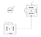
図1は、本実施形態におけるデジタルカメラ1の機能ブロックを示す図である。デジタルカメラ1は、3つの主要コンポーネントとして、操作部10と実行部20と無線通信デバイス30とを含み構成される。
FIG. 1 is a diagram showing functional blocks of the
操作部10は、ユーザとの対話を行うUIコンポーネントであり、ユーザがデジタルカメラ1を操作する際に使用する操作ボタン等のユーザインタフェースの制御を行う。実行部20は、デジタルカメラ1の撮影や画像データ保存等の機能を統合するコンポーネントである。操作部10および実行部20は、下記に示すインタフェース回路103,203を介し、汎用の通信プロトコルを用いて相互に通信を行う。
The
本実施形態では、インタフェース回路103,203の実装プロトコルとしてPTP(Picture Transfer Protocol)を用い、そのインタフェースのベースとなる通信プロトコルにはTCP/IPを用いる。そして、操作部10と実行部20は、PTPコマンド及びその応答を通信路40であるソケットストリームを介して交換しあうことで、相互に通信を行う。
In the present embodiment, PTP (Picture Transfer Protocol) is used as a mounting protocol for the
さらに、デジタルカメラ1は、ネットワークを介して他のデジタルカメラ等と通信を行うために、無線通信デバイス30を備える。デジタルカメラ1は、無線通信デバイス30を介して、通信規格802.11(WiFi)の通信方式に基づき、他のデジタルカメラ等と無線通信を行う。
Furthermore, the
図2は、操作部10および実行部20のさらに詳細な機能ブロックを示す図である。操作部10は、シャッタボタンや各種撮影モードの切り替えボタン等の操作ボタン、画像を表示するディスプレイ等を含むUI回路101と、操作部10全体の制御を行う制御回路102と、実行部20との通信や無線通信デバイスを介した他のデジタルカメラ等との通信を行う際の通信インタフェースとなるインタフェース回路103とを含む。
FIG. 2 is a diagram illustrating further detailed functional blocks of the
実行部20は、撮影処理を行う撮影処理回路201と、実行部20全体の制御を行う制御回路202と、操作部10との通信や通信無線通信デバイスを介した他のデジタルカメラ等との通信を行う際の通信インタフェースとなるインタフェース回路203と、制御回路202が撮影処理回路201を制御する際の同期クロックを発生する同期クロック発生回路204を含む。
The
さらに、図3は、実行部20に含まれる撮影処理回路201をより詳細に示した機能ブロック図である。図3において、レンズ211を通過した画像の光量は、露光制御機構212で制御され、撮像素子213の撮像画面上に被写体像が結像される。撮像素子213は、所定のクロックにより結像された被写体像を撮像信号として信号処理回路214に出力する。信号処理回路214は、入力された撮像信号に対して輝度信号処理、色分離等の信号処理を行う。A/D回路215は、信号処理後の撮像信号をアナログ信号からデジタル信号に変換する。A/D変換された信号は、画像処理回路216でガンマ補正などの種々の画像処理が施されて、画像データとしてメモリ217に保存される。また、ストロボ機構218において、必要に応じて被写体にストロボ光が照射される。
Further, FIG. 3 is a functional block diagram showing the
このように構成されたデジタルカメラにおいて、ユーザからの操作指示をUI回路101を介して制御回路102が受け取り、制御回路102がその操作指示に応じた制御信号をインタフェース回路103を介して実行部20に出力する。制御回路202は、インタフェース回路203を介して操作部10から制御信号を受け取り、その制御信号に基づいて撮影処理回路201を制御し、撮影処理を行う。
In the digital camera configured as described above, the
本実施形態では、上記のように構成されたデジタルカメラを2台(カメラA、カメラBと定義する)用意する。そして、カメラAの操作部10AとカメラBの実行部20Bとの間で通信路を確立し、カメラAとカメラBとで無線通信を行う。このとき、カメラAを撮影用として機能させ、カメラAの制御の下、カメラBを外部ストロボ用として機能させる。これにより、特殊な装置を用意することなく、外部ストロボを利用した撮影を実行する。 In the present embodiment, two digital cameras (defined as camera A and camera B) configured as described above are prepared. Then, a communication path is established between the operation unit 10A of the camera A and the execution unit 20B of the camera B, and wireless communication is performed between the camera A and the camera B. At this time, the camera A is made to function for photographing, and the camera B is made to function for an external strobe under the control of the camera A. Thus, shooting using an external strobe is performed without preparing a special device.
ここで、図4に示す図を用いて、カメラAを撮影用として、カメラBを外部ストロボ用として機能させた場合の処理フローについてさらに説明する。なお、カメラAとカメラBとは、図5に示すような位置に設置する。すなわち、カメラAは、被写体2の所望の撮影位置に配置し、カメラBは、被写体2に対して所望のストロボ光を与えられる位置に配置する。 Here, the processing flow in the case where the camera A is used for photographing and the camera B is used for an external strobe will be further described with reference to FIG. The cameras A and B are installed at positions as shown in FIG. That is, the camera A is arranged at a desired shooting position of the subject 2, and the camera B is arranged at a position where a desired strobe light is given to the subject 2.
図4において、まず、被操作カメラとなるカメラBの動作モードを外部操作モードに設定するために、操作部10Bから実行部20Bに外部操作モード設定指令を出力する(S101)。実行部20Bは、外部操作モード設定指令を受けて、通常の撮影モードから外部操作モードにモード切り替えを行う(S102)。実行部20Bは、外部操作モードに設定されると、操作カメラとなるカメラAからの接続要求が来るまで待機状態となる。 4, first, an external operation mode setting command is output from the operation unit 10B to the execution unit 20B in order to set the operation mode of the camera B as the operated camera to the external operation mode (S101). In response to the external operation mode setting command, the execution unit 20B switches the mode from the normal shooting mode to the external operation mode (S102). When the execution unit 20B is set to the external operation mode, the execution unit 20B enters a standby state until a connection request is received from the camera A serving as the operation camera.
一方、カメラAの操作部10Aは、ユーザからの外部ストロボ利用指令を受けて(S103)、操作部10Aは、実行部20Bとの間の通信路の確立処理を行う(S104)。なお、操作部10Aと実行部20Bと通信路の確立方法については後ほど説明する。 On the other hand, the operation unit 10A of the camera A receives an external strobe use command from the user (S103), and the operation unit 10A performs processing for establishing a communication path with the execution unit 20B (S104). The operation unit 10A, the execution unit 20B, and the communication path establishment method will be described later.
次いで、操作部10Aは、S104にて確立された通信路を介して実行部20Bに動画送信を要求し(S105)、実行部20Bは、それを受けて、実行部20Bにおいて得られる被写体2の動画を操作部10Aに送信する(S106)。操作部10Aは、得られた動画をカメラAのディスプレイに表示する(S107)。これにより、ユーザは、カメラAのディスプレイ上でカメラBの視点での被写体2を見ることができ、被写体2の位置やポーズを修正することができる。 Next, the operation unit 10A requests the execution unit 20B to transmit a moving image via the communication path established in S104 (S105), and the execution unit 20B receives the request and transmits the subject 2 obtained in the execution unit 20B. The moving image is transmitted to the operation unit 10A (S106). The operation unit 10A displays the obtained moving image on the display of the camera A (S107). As a result, the user can see the subject 2 from the viewpoint of the camera B on the display of the camera A, and can correct the position and pose of the subject 2.
続いて、操作部10Aはユーザによってシャッタボタンが半押しされたことを検知すると(S108)、実行部20A,実行部20Bに対して撮影パラメータ計算指令を出力する(S109)。それを受けて、実行部20A,実行部20Bは、撮影パラメータの計算を実行する(S110)。ここで、撮影パラメータとは、被写体2を撮影する際に必要なパラメータであり、撮像素子213から出力される撮像信号や別途カメラに設けられた外部センサから出力される信号に基づいて計算される。なお、この計算により、撮影シーンに応じた露光時間やストロボ発光時間が計算される。これらのパラメータをもとに、制御回路202が撮影処理回路201を制御して、AE(Auto exposure)、AF(Auto Focus)、AWB(Auto White balance)などを行う。また本実施形態では、カメラBは、外部ストロボとして用いられるため、被写体2の露光量の大きさに関わらず、強制的にストロボ発光するものとしてパラメータの計算が行われる。
Subsequently, when the operation unit 10A detects that the shutter button is half-pressed by the user (S108), the operation unit 10A outputs an imaging parameter calculation command to the execution unit 20A and the execution unit 20B (S109). In response to this, the execution unit 20A and the execution unit 20B execute calculation of imaging parameters (S110). Here, the shooting parameter is a parameter required when shooting the subject 2 and is calculated based on an image pickup signal output from the
その後、ストロボの充電が完了した時点で実行部20Bから操作部10Aに対してストロボ充電の完了が通知される(S111)。操作部10Aは、その通知を受けて、例えば、LEDを点灯させるなどしてユーザに撮影準備が完了したことを通知する(S112)。なお、すでにストロボ充電がフル充電状態であれば、この完了通知は即座に行われる。 Thereafter, when the charging of the strobe is completed, the execution unit 20B notifies the operation unit 10A of the completion of the strobe charging (S111). Upon receiving the notification, the operation unit 10A notifies the user that the preparation for photographing has been completed, for example, by turning on an LED (S112). If the strobe is already fully charged, this completion notification is made immediately.
ここで、撮影準備の完了を認知したユーザがシャッタボタンを全押しすると(S113)、操作部10Aは、それを受けて、カメラAにおいて露光を開始するタイミングを示すTxと、カメラBにおいてストロボ発光を開始するタイミングを示すTfとを決定し(S114)、決定したTxで露光を開始するように実行部20Aに指令を出すとともに(S115)、決定したTfにてストロボ発光を開始するように実行部20Bに指令を出す(S116)。この時Txは上記S115とS116とに要する時間を考慮して計算される。 Here, when the user who has recognized the completion of the shooting preparation fully presses the shutter button (S113), the operation unit 10A receives the Tx indicating the timing of starting exposure in the camera A and the flash emission in the camera B. Is determined (S114), and a command is issued to the execution unit 20A to start exposure at the determined Tx (S115), and the strobe emission is started at the determined Tf. A command is issued to the unit 20B (S116). At this time, Tx is calculated in consideration of the time required for S115 and S116.
その後、実行部20Aは、Txのタイミングまで待機して、Txのタイミングで露光を開始する(S117)。一方、実行部20Bは、Tfのタイミングまで待機して、Tfのタイミングでストロボ発光を開始する(S118)。 Thereafter, the execution unit 20A waits until the timing of Tx and starts exposure at the timing of Tx (S117). On the other hand, the execution unit 20B waits until the timing of Tf and starts strobe light emission at the timing of Tf (S118).
これにより、カメラAは、カメラBに備えられたストロボ機構を利用して、外部ストロボによる撮影を行うことができる。 As a result, the camera A can take an image with the external strobe using the strobe mechanism provided in the camera B.
しかしながら、カメラAとカメラBとが無線ネットワークを介して同期接続され、上記のようにカメラAで露光を行い、カメラBでストロボ発光を行う場合、カメラAとカメラBとの間で同期誤差が生じていると、適切に外部ストロボによる撮影を行うことができない場合がある。 However, when camera A and camera B are connected synchronously via a wireless network, exposure is performed with camera A as described above, and flash emission is performed with camera B, there is a synchronization error between camera A and camera B. If this occurs, it may not be possible to properly shoot with an external flash.
そこで、本実施形態では、無線ネットワークを介して接続されたカメラAとカメラBとの間で生じる同期誤差を考慮して、TxとTfを決定する。 Therefore, in the present embodiment, Tx and Tf are determined in consideration of a synchronization error occurring between the camera A and the camera B connected via the wireless network.
具体的には、カメラAとカメラBとの間での同期誤差を±Ie、露光時間をIx、ストロボ発光時間をIfとすると、TxからTfまでの時間、すなわち、TxとTfとの時間差IdをIeよりも大きく、かつ、露光が終了するまでに、ストロボ発光を終了させるために、時間差Idとストロボ発光時間Ifと同期誤差Ieとの合計(Id+If+Ie)が露光時間Ixよりも小さくなるように、TxとTfとを設定する。これにより、カメラAとカメラBとの間での同期誤差が生じても、カメラAの露光時間内に、カメラBのストロボ発光を開始して、終了させることができる。TxとTfとの関係について、さらに図6A〜6Eを用いて説明する。 Specifically, if the synchronization error between camera A and camera B is ± Ie, the exposure time is Ix, and the strobe emission time is If, the time from Tx to Tf, that is, the time difference Id between Tx and Tf. Is greater than Ie, and in order to end the flash emission before the end of exposure, the sum of the time difference Id, the flash emission time If, and the synchronization error Ie (Id + If + Ie) is made smaller than the exposure time Ix. , Tx and Tf are set. Thus, even if a synchronization error occurs between the camera A and the camera B, the flash emission of the camera B can be started and ended within the exposure time of the camera A. The relationship between Tx and Tf will be further described with reference to FIGS.
図6Aに示すように、TxとTfとの時間差IdがIeよりも大きければ、カメラBがストロボ発光をTfのタイミングで開始すべきところ、図6Bに示すように、(Tf−Ie)のタイミングでストロボ発光を開始したとしても、カメラAの露光時間内でカメラBのストロボ発光を開始することができる。 As shown in FIG. 6A, if the time difference Id between Tx and Tf is larger than Ie, the camera B should start strobe emission at the timing of Tf. As shown in FIG. 6B, the timing of (Tf−Ie) Even if the flash emission is started at, the flash emission of the camera B can be started within the exposure time of the camera A.
しかし、図6Cに示すように、TxとTfとの時間差IdがIeよりも小さいと、図6Dに示すように、(Tf−Ie)のタイミングでストロボ発光を開始した場合、カメラAの露光時間内でカメラBのストロボ発光を開始できない場合がある。よって、カメラAとカメラBとの間での同期誤差が生じた場合、カメラAは、カメラBに備えられたストロボ機構を利用して、外部ストロボによる撮影を適切に行えない場合がある。 However, as shown in FIG. 6C, when the time difference Id between Tx and Tf is smaller than Ie, as shown in FIG. 6D, when the strobe emission is started at the timing of (Tf−Ie), the exposure time of the camera A In some cases, the flash of the camera B cannot be started. Therefore, when a synchronization error occurs between the camera A and the camera B, the camera A may not be able to appropriately perform shooting with an external strobe using the strobe mechanism provided in the camera B.
また、図6Eに示すように、時間差Idとストロボ発光時間Ifと同期誤差Ieとの合計(Id+If+Ie)が露光時間Ixより大きいと、露光時間内にストロボ発光が終了しない場合がある。よって、この場合も、カメラAは、カメラBに備えられたストロボ機構を利用して、外部ストロボによる撮影を適切に行えない可能性がある。 Further, as shown in FIG. 6E, if the sum (Id + If + Ie) of the time difference Id, the strobe light emission time If, and the synchronization error Ie is larger than the exposure time Ix, the strobe light emission may not end within the exposure time. Therefore, in this case as well, there is a possibility that the camera A cannot appropriately perform photographing with the external strobe by using the strobe mechanism provided in the camera B.
以上より、本実施形態では、TxとTfとの時間差Idを予め想定されている同期誤差Ieよりも大きく、かつ、時間差Idとストロボ発光時間Ifと同期誤差Ieとの合計(Id+If+Ie)が露光時間Ixよりも小さくなるように、TxとTfとを設定する。これにより、カメラAとカメラBとの間での同期誤差が生じても、カメラAによる露光とカメラBによるストロボ発光とを同期させて適切に撮影を行うことができる。 As described above, in the present embodiment, the time difference Id between Tx and Tf is larger than the synchronization error Ie assumed in advance, and the sum (Id + If + Ie) of the time difference Id, the strobe light emission time If, and the synchronization error Ie is the exposure time. Tx and Tf are set so as to be smaller than Ix. As a result, even if a synchronization error occurs between the camera A and the camera B, it is possible to appropriately perform photographing by synchronizing the exposure by the camera A and the strobe light emission by the camera B.
一般的に、露光時間Ixは最短でも1msであり、ストロボ発光時間Ifは20μs前後である。また、カメラAとカメラBとの間の無線通信を通信規格802.11(WiFi)の通信方式を用いる場合、同期誤差は、規格上、数10μsを超えない。よって、例えば、TxとTfとの時間差Idを100μsとすれば、カメラAとカメラBとの間で同期誤差が生じてもカメラAの露光時間内にカメラBのストロボ発光を開始かつ終了することができる。なお、同期誤差Ieは、通信規格や仕様で定められた値や、実験値をもとに定めればよい。 Generally, the exposure time Ix is 1 ms at the shortest, and the strobe light emission time If is around 20 μs. Further, when the communication method of the communication standard 802.11 (WiFi) is used for the wireless communication between the camera A and the camera B, the synchronization error does not exceed several tens of μs in the standard. Thus, for example, if the time difference Id between Tx and Tf is 100 μs, the flash emission of the camera B is started and ended within the exposure time of the camera A even if a synchronization error occurs between the camera A and the camera B. Can do. The synchronization error Ie may be determined based on a value determined by a communication standard or specification or an experimental value.
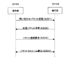
ここで、S104で行われるカメラAの操作部10AとカメラBの実行部20Bとの間の通信路確立フローについて図7に示すフローチャートを用いて説明する。 Here, the communication path establishment flow between the operation unit 10A of the camera A and the execution unit 20B of the camera B performed in S104 will be described with reference to the flowchart shown in FIG.
まず、カメラBを操作して、カメラBを外部操作モードに設定しておく。つまり、カメラBの実行部Bを、他の操作部からの接続要求、つまり下記に示す問い合わせパケットの受信待機状態にしておく。この状態において、ユーザからの外部ストロボ利用指示に基づいて、操作部10Aは、実行部20Bを探すためにカメラBの無線通信デバイスを認識した後、問い合わせパケットを送信する(S201)。本実施形態では、問い合わせパケットにUDPパケットを使用し、TCPネットワーク上にマルチキャストする。この問い合わせパケットには、カメラAに割り当てられたIPアドレスが含まれている。実行部20Bは、問い合わせパケットを受信すると、問い合わせパケットに含まれるIPアドレスに向けて、UDPパケットで応答パケットを送信し、ネットワーク上での自身の場所(つまり、カメラBに割り当てられたIPアドレスとポート番号)を操作部10Aに知らせる(S202)。応答パケットには、カメラBのIPアドレスとポート番号が含まれており、操作部10Aはこのパケットを受信すると、ソケット接続要求を実行部20Bに向けて出力し、実行部20Bとの間のソケット接続を試みる(S203)。そして、実行部20Bがこのソケット接続要求を受け入れると、操作部10Aと実行部20Bとの間に通信路としてソケットストリームが確立される(S204)。なお、カメラAとカメラBとの同期取りは、WiFiプロトコルの1つの機能により実現される。以上の処理により、カメラAの操作部10AとカメラBの実行部20Bとの間の通信路が確立される。 First, the camera B is operated to set the camera B to the external operation mode. That is, the execution unit B of the camera B is set in a standby state for receiving a connection request from another operation unit, that is, the inquiry packet shown below. In this state, based on an external strobe use instruction from the user, the operation unit 10A recognizes the wireless communication device of the camera B to search for the execution unit 20B, and then transmits an inquiry packet (S201). In this embodiment, a UDP packet is used as the inquiry packet and multicasted over the TCP network. This inquiry packet includes the IP address assigned to the camera A. When the execution unit 20B receives the inquiry packet, the execution unit 20B transmits a response packet as a UDP packet toward the IP address included in the inquiry packet, and the location on the network (that is, the IP address assigned to the camera B) The port number is notified to the operation unit 10A (S202). The response packet includes the IP address and port number of the camera B. When the operation unit 10A receives this packet, the operation unit 10A outputs a socket connection request to the execution unit 20B, and the socket with the execution unit 20B. Connection is attempted (S203). When the execution unit 20B accepts this socket connection request, a socket stream is established as a communication path between the operation unit 10A and the execution unit 20B (S204). Note that the synchronization between the camera A and the camera B is realized by one function of the WiFi protocol. With the above processing, a communication path between the operation unit 10A of the camera A and the execution unit 20B of the camera B is established.
[第2の実施の形態]
続いて、本発明の第2の実施の形態について、以下図面を用いて説明する。
[Second Embodiment]
Next, a second embodiment of the present invention will be described below with reference to the drawings.
各カメラの構成は、第1の実施の形態と同じであり、図1〜図3に示すとおりである。図8は、本実施形態における各カメラと被写体2との配置関係の一例を示す図である。本実施形態では、図8に示すように近傍に配置した複数のカメラを無線ネットワークを介して接続し、被写体2を同時にかつ連続的に撮影する場合を想定している。 The configuration of each camera is the same as that of the first embodiment, as shown in FIGS. FIG. 8 is a diagram illustrating an example of an arrangement relationship between each camera and the subject 2 in the present embodiment. In the present embodiment, it is assumed that a plurality of cameras arranged in the vicinity as shown in FIG. 8 are connected via a wireless network and the subject 2 is photographed simultaneously and continuously.
このようなカメラの配置において、複数のカメラが同時に被写体2を撮影する場合、各カメラが同時にストロボ発光すると、被写体2が過度に明るくなってしまう場合がある。そこで、本実施形態では、1回の撮影では1台のカメラのみにストロボ発光をさせ、他のカメラはそのカメラのストロボ発光を利用して被写体2の撮影を行う。 In such a camera arrangement, when a plurality of cameras shoot the subject 2 at the same time, the subject 2 may become excessively bright if the cameras emit strobe light simultaneously. Therefore, in the present embodiment, only one camera emits strobe light in one shooting, and the other cameras use the strobe light of the camera to take a picture of the subject 2.
また、1台のカメラにおいてストロボ発光を行いながら連続撮影を行う場合、ストロボ発光を伴う撮影を行った後、さらにストロボ発光を伴う撮影を開始するには、ストロボ発光のための充電が完了するまで待機する必要がある。そのため、所定時間内に撮影できる回数は、その充電時間によって制限されてしまう場合がある。そこで、本実施形態では、充電時間に制限されることなく、所定時間内に撮影できる回数をより多くするために、ストロボ発光するカメラを順次切り替えながら連続撮影を行う。 In addition, when performing continuous shooting with flash firing on one camera, after shooting with flash firing, to start shooting with flash firing until charging for flash firing is completed. I need to wait. Therefore, the number of times that shooting can be performed within a predetermined time may be limited by the charging time. Therefore, in the present embodiment, continuous shooting is performed while sequentially switching the cameras that emit the strobe light in order to increase the number of times that shooting can be performed within a predetermined time without being limited by the charging time.
さらに、複数のカメラを無線ネットワークを介して接続し、ストロボを使用した同時撮影を行う場合、カメラ同士の同期がとれていないと、適切にストロボを使用した同時撮影を行うことはできない。しかしながら、カメラ同士の間で取られた同期には誤差が生じることがある。そこで、本実施形態では、カメラ同士の間で取られた同期誤差を考慮して、複数カメラによるストロボを使用した同時撮影を行う。 Further, when a plurality of cameras are connected via a wireless network and simultaneous shooting using a strobe is performed, simultaneous shooting using a strobe cannot be performed properly unless the cameras are synchronized. However, errors may occur in the synchronization taken between the cameras. Therefore, in the present embodiment, simultaneous shooting using a strobe with a plurality of cameras is performed in consideration of a synchronization error taken between the cameras.
ここで、本実施形態について、(1)同時撮影前の準備処理および(2)同時撮影時にストロボ発光を行うカメラの操作部の処理について、それぞれフローチャートを用いて順番に説明する。 Here, regarding the present embodiment, (1) preparation processing before simultaneous shooting and (2) processing of the operation unit of the camera that emits strobe light at the time of simultaneous shooting will be described in order using flowcharts.
[同時撮影前の準備処理]
本実施形態では、同時撮影を行う前にまずストロボ発光を行うカメラの順番を予め定め、各カメラにその順番及びその順番に対応するIPアドレスの登録をしておくために、カメラの画像撮影機能を利用して、各カメラの順番およびIPアドレス登録を行う。以下、この順番登録の処理手順について説明する。
[Preparation process before simultaneous shooting]
In the present embodiment, before performing simultaneous shooting, first, the order of cameras that perform strobe light emission is determined in advance, and each camera is registered with the order and the IP address corresponding to the order. Is used to register the order and IP address of each camera. The order registration processing procedure will be described below.
まず、図8に示すように、それぞれ近傍に配置した各カメラの前に撮影用順番札3を据える。これはカメラに順番をつけるためのもので、例えば番号を書いた札でもよいし、別々の色の札でもよい。ここでは、カメラA〜カメラDの前にそれぞれ「1」、「2」、「3」、「4」の数字が描かれた順番札を据える。
First, as shown in FIG. 8, a
続いて、ユーザは各カメラを操作して、各カメラの操作部に順番登録指令を出す。この登録指令を受けて、各操作部10は、図9のフローチャートに示す処理を行う。以下、n番目(nは、1〜Nまでの整数であり、Nは、同時撮影を行うカメラの総台数を示す)のカメラの操作部及び実行部を、操作部10n及び実行部20nと表現する。
Subsequently, the user operates each camera and issues an order registration command to the operation unit of each camera. In response to this registration command, each
図9において、操作部10nは、順番登録指令を受け取り(S301)、その指令に基づいて自身の実行部20nに撮影処理を実行させ、撮影用順番札を撮影させる(S302)。次いで、操作部10nは、撮影して得られた画像データを実行部20nから取得して、その画像データについて文字認識処理を実行する(S303)。さらにその処理結果に基づいて、自身の撮影順番を特定し、その撮影順番に応じたIPアドレスを決定した後、それらをメモリに登録する(S304)。なお、文字認識処理は、OCR(Optical Character Recognition)等の一般的な文字認識の技術を用いればよく、例えば、各撮影用順番札を撮影して得られた各順番画像データを順番(数字)と対応付けて予め記憶しておき、それらの順番画像データと、自身が撮影して得られた画像データとの類似度を計算し、類似度が最も高い順番画像データに対応する順番を自身に割り当てられた撮影順番と決定する。
In FIG. 9, the
また、撮影順番に応じたIPアドレスは、次のように決定する。まず、IPアドレスのネットワーク部については予め定めておく。IPv4の場合、例えば、ネットワーク部を上位24ビットと定め、「192.168.1.*」をネットワーク部として定める。そして、各撮影順番に対応する数字をホスト部に割り当てる。よって、この場合、撮影順番が「1」番のカメラに、「1」の順番札を撮影させることで、IPアドレスとして「192.168.1.1」が登録され、撮影順番が「4」番のカメラに、「4」の順番札を撮影させることで、IPアドレスとして「192.168.1.4」が登録される。 The IP address corresponding to the shooting order is determined as follows. First, the network part of the IP address is determined in advance. In the case of IPv4, for example, the network part is defined as the upper 24 bits, and “192.168.1. *” Is defined as the network part. Then, a number corresponding to each shooting order is assigned to the host unit. Therefore, in this case, by causing the camera with the shooting order “1” to take the “1” turn tag, “192.168.1.1” is registered as the IP address, and the shooting order is “4”. No. camera is photographed with a turn tag “4”, so that “192.168.1.4” is registered as an IP address.
このようにして、各カメラについて撮影順番とIPアドレスが登録されると、次に、カメラ間を、図10に示すようにループ上に接続する。すなわち、前段カメラの操作部nと後段カメラの実行部n+1との間にそれぞれ通信路40を確立し、さらに、最後段のカメラの操作部Nと最前段のカメラの実行部1との間に通信路40を確立する。
ここで、図11に示すフローチャートを用いて、図10に示すような通信路の確立手順について説明する。
When the shooting order and the IP address are registered for each camera in this way, the cameras are connected on a loop as shown in FIG. That is, a
Here, a procedure for establishing a communication path as shown in FIG. 10 will be described using the flowchart shown in FIG.
ユーザは何れかのカメラnを操作して、そのカメラの操作部10nに対して接続指示を出す。操作部10nは、その接続指示を受信すると(S401)と、自身のカメラに割り当てられたIPアドレスに基づいて、後段のカメラn+1のIPアドレスを特定する(S402)。具体的には、操作部10nは、自身に登録されたIPアドレスのホスト部の値に1をインクリメントした値を後段のカメラn+1のIPアドレスとして特定する。
The user operates one of the cameras n and issues a connection instruction to the
続いて、操作部10nは、特定したIPアドレスが割り当てられた後段のカメラn+1の実行部20n+1との間に通信路が確立されているか否かを判定する(S403)。判定の結果、その通信路が確立されていなければ、操作部10nは、その特定したIPアドレスを元に後段の実行部20n+1との間で、通信路の確立処理、つまり、図7に示す接続・同期処理を実行する(S404)。次いで、操作部10nは、処理の結果、後段の実行部20n+1との間に通信路を確立することができたか否かを判定する(S405)。判定の結果、通信路の確立に成功した場合は、その後段のカメラの操作部10n+1に向けて、さらに後段の実行部n+2との間に通信路を確立させるために、接続指示を送信する(S406)。
Subsequently, the
一方、S405での判定の結果、通信路が確立できなかった場合、操作部10nは、自身より後段にはカメラが存在しない、つまり、自身が最後段のカメラnであると判断する。ここで、各カメラには、1から順番に番号が定められているため、最後段のカメラNは、自身のIPアドレスから自分の順番を把握することで、今回確立したループネットワークに含まれるカメラの総台数を把握することができる。このカメラ台数の情報は、各カメラが下記に示す同時撮影処理を行う際に用いるため、各カメラに向けてブロードキャストされる(S407)。これを受けて各カメラの操作部は、台数情報をメモリに記憶しておく。この台数情報の使用方法については後述する。その後、最後段のカメラの操作部10Nは、最前段のカメラの実行部201との間に通信路の確立を行う(S408)。
On the other hand, if the communication path cannot be established as a result of the determination in S405, the
また、S403での判定の結果、すでに後段のカメラの実行部20n+1との間に通信路が確立されていると判定した場合、図10に示すようなループネットワークの構築が完了したと判断して、その操作部20nは、接続完了通知を行う(S409)。接続完了通知は、例えば、ディスプレイ等にその情報を表示することで行えばよい。
If it is determined in S403 that the communication path has already been established with the
なお、S406では、操作部10nは、後段の実行部20n+1との間で通信路が確立された後、後段の操作部10n+1に向けて接続指示を送信している。しかし、操作部10nと後段の操作部10n+1とは通信路が確立されていないため、操作部10nは直接後段の操作部10n+1に対して接続指示をユニキャストにより送信することはできない。そこで、操作部10nは、通信路を確立した後段の実行部20n+1を介して接続指示を後段の操作部10n+1に対して送信する。具体的には、操作部10nは、まず接続指示の内容が引数に示されているPTPイベントを後段の実行部20n+1に送信する。実行部20n+1は、そのPTPイベントを受信すると、そのPTPイベントの引数に示された内容に基づいて、自身の操作部10n+1に転送すべきPTPイベントと判断し、そのPTPイベントを操作部10n+1に送信する。操作部10n+1はそのPTPイベントの引数を参照することで、接続指示を受信したことを認識し、後段の実行部20n+2との間での通信路確立処理を実行する。
In S406, the
[同時撮影時にストロボ発光を行うカメラの操作部の処理手順]
続いて、同時撮影時にストロボ発光を行うカメラの操作部の処理手順について、図12に示すフローチャートを用いて説明する。
[Processing procedure of the camera operation unit that emits strobe light during simultaneous shooting]
Next, a processing procedure of the operation unit of the camera that emits strobe light at the time of simultaneous shooting will be described with reference to a flowchart shown in FIG.
まず操作部10nは、撮影指示の入力を受け付ける(S501)。ここで、撮影指示は、1番目のカメラの場合、ユーザがUIを操作することで、例えばシャッターボタンを押下することで、操作部に入力される。また、それ以外のカメラの場合は、前段のカメラから無線ネットワークを介して撮影指示が操作部に入力される。
First, the
操作部10nは、その撮影指示に応じて、ストロボ強制発光を条件として撮影パラメータの計算を行うための指示をブロードキャストする(S502)。次いで、操作部10nは、露光を開始するタイミングを示すTxと、ストロボ発光を開始するタイミングを示すTfとを決定する(S503)。ここで、決定されるTxとTfとは、第1の実施の形態と同様に、TxとTfとの時間差Idを各カメラ間で生じる同期誤差Ieよりも大きく、かつ、時間差Idとストロボ発光時間Ifと同期誤差Ieとの合計(Id+If+Ie)が露光時間Ixよりも小さくなるように、TxとTfとを設定する。なお、ストロボ発光時間Ifは、S502での撮影パラメータの計算により求められるものである。また、同期誤差Ieは、第1の実施の形態と同様に、通信規格や仕様で定められた値や、実験値をもとに定めればよい。
In response to the shooting instruction, the
さらに、操作部10nは、決定したTxにてストロボ禁止で露光を開始するための指示をブロードキャストする(S504)。この指示を受けて、各実行部は、S502での指示に基づき計算した撮影パラメータを用いて、Txのタイミングで露光を開始する。続いて、操作部10nは、自身の実行部20nに対して、Tfにおいてストロボ発光を開始するための指示をユニキャストし(S505)、この指示を受けて、実行部20nは、S502での指示に基づき計算した撮影パラメータを用いて、Tfのタイミングでストロボ発光を開始する。
Further, the
その後、操作部10nは、すべての実行部から撮影完了通知を受信するまで待機する(S506)。なお、撮影完了通知は、一連の撮影処理が完了した時点で各実行部から操作部10nにユニキャストされる。一連の撮影処理とは、露光が終了し、得られた撮像信号に対して所定の画像処理が施され、画像データとしてメモリに保存されるまでの処理のことをいう。
After that, the
操作部10nは、すべての実行部から撮影完了通知を受信すると、後段の操作部に撮影指示を送信する(S507)。
When receiving the shooting completion notification from all execution units, the
以上、上記処理を実行することで、1台のカメラがストロボ発光をして撮影を行い、他のカメラが同時にストロボ無しで撮影を行う。つまり、ストロボ発光を行うカメラをホストカメラと定義した場合、ホストカメラが予め定められた順番で順次切り替わりながら、連続撮影を行う。 As described above, by executing the above processing, one camera performs flash photography to shoot, and the other cameras shoot simultaneously without a flash. That is, when a camera that emits strobe light is defined as a host camera, continuous shooting is performed while the host camera is sequentially switched in a predetermined order.
図13は、本実施形態におけるカメラA〜Dの撮影の流れを示すイメージ図である。このように、本実施形態では、1回の撮影処理においてストロボ発光を行うカメラは1台であり、順次ストロボ発光を担当するホストカメラが切り替わりながら撮影を連続的に行う。 FIG. 13 is an image diagram showing a flow of photographing by the cameras A to D in the present embodiment. As described above, in this embodiment, only one camera emits strobe light in one shooting process, and shooting is continuously performed while the host cameras in charge of strobe light emission are sequentially switched.
なお、連続撮影は、何れかのカメラの電源を切ることで終了させることができる。また、予め撮影回数を定めておき、最初にホストとなるカメラ、つまりユーザが操作するカメラの操作部において、撮影回数をカウントしていき、所定回数になった時点で各実行部に撮影終了指示をブロードキャストすることで、連続撮影を終了してもよい。さらに、撮影回数ではなく、撮影時間を定めておき、所定の時間経過した時点で各実行部に撮影終了指示をブロードキャストしてもよい。 Note that continuous shooting can be terminated by turning off any camera. In addition, the number of times of photographing is determined in advance, and the number of times of photographing is counted first at the operation unit of the camera that is the host, that is, the camera operated by the user. Broadcast may be terminated. Furthermore, instead of the number of times of photographing, a photographing time may be determined, and a photographing end instruction may be broadcast to each execution unit when a predetermined time has elapsed.
本実施形態によれば、各カメラが同時にストロボ発光することで、被写体が過度に明るくなることを防止することができる。また、ストロボ発光するカメラを順次切り替えながら連続撮影を行うことにより、連続撮影時における充電時間の依存を少なくし、所定時間内に撮影できる回数をより多くすることができる。加えて、露光開始タイミングTxとストロボ発光タイミングTfとの時間差Idを予め想定されているカメラ間で生じる同期誤差Ieよりも大きく設定し、かつ、時間差Idとストロボ発光時間Ifと同期誤差Ieとの合計(Id+If+Ie)が露光時間Ixよりも小さくなるように、TxとTfとを設定することで、このような同期誤差が生じても、各カメラの露光時間内にストロボ発光を行うことができ、複数カメラによるストロボを使用した同時撮影を適切に行うことができる。 According to the present embodiment, it is possible to prevent the subject from becoming excessively bright by simultaneously flashing each camera. In addition, by performing continuous shooting while sequentially switching the cameras that emit the flash light, the dependence on the charging time during continuous shooting can be reduced, and the number of times that shooting can be performed within a predetermined time can be increased. In addition, the time difference Id between the exposure start timing Tx and the strobe light emission timing Tf is set to be larger than the synchronization error Ie generated between the cameras, and the time difference Id, the strobe light emission time If, and the synchronization error Ie By setting Tx and Tf so that the total (Id + If + Ie) is smaller than the exposure time Ix, even if such a synchronization error occurs, strobe light emission can be performed within the exposure time of each camera. Simultaneous shooting using strobes from multiple cameras can be performed appropriately.
1 デジタルカメラ、10 操作部、20 実行部、30 無線通信デバイス、40 通信路、101 UI回路、102,202 制御回路、103,203 インタフェース回路、201 撮影処理回路、204 同期クロック発生回路 、211 レンズ、212 露光制御機構、213 撮像素子、214 信号処理回路、215 A/D回路、216 画像処理回路、217 メモリ、218 ストロボ機構。
DESCRIPTION OF
Claims (15)
前記撮影用カメラは、
露光開始時点Txとストロボ発光開始時点Tfとを決定する決定手段と、
前記ストロボ発光開始時点Tfにストロボ発光を開始させるためのストロボ発光開始指令を出力する発光開始指令出力手段と、
前記露光開始時点Txに露光を開始させるための露光開始指令を出力する露光開始指令出力手段と、
前記露光開始指令に応じて前記露光開始時点Txに露光を開始するように前記露光制御機構を制御する露光制御手段と、
を備え、
前記ストロボ用カメラは、
前記無線ネットワークを介して受信した前記ストロボ発光開始指令に応じて、前記ストロボ発光開始時点Tfにストロボ発光を開始するように前記ストロボ機構を制御する発光制御手段を、
備え、
前記決定手段は、
前記露光開始時点Txが前記ストロボ発光開始時点Tfより早い開始時点となり、前記露光開始時点Txと前記ストロボ発光開始時点Tfとの時間差が、前記撮影用カメラと前記外部ストロボ用カメラとの同期誤差よりも大きく、さらに、露光が完了する前にストロボ発光が終了するように、露光開始時点Txとストロボ発光開始時点Tfとを決定することを特徴とするカメラシステム。 A camera system in which a shooting camera with an exposure control mechanism and a flash camera with a flash mechanism are connected synchronously via a wireless network,
The photographing camera is
Determining means for determining an exposure start time Tx and a strobe light emission start time Tf;
A light emission start command output means for outputting a strobe light emission start command for starting strobe light emission at the strobe light emission start time Tf;
Exposure start command output means for outputting an exposure start command for starting exposure at the exposure start time Tx;
Exposure control means for controlling the exposure control mechanism to start exposure at the exposure start time Tx in response to the exposure start command;
With
The strobe camera is
In accordance with the strobe light emission start command received via the wireless network, a light emission control means for controlling the strobe mechanism to start the strobe light emission at the strobe light emission start time Tf,
Prepared,
The determining means includes
The exposure start time Tx is a start time earlier than the strobe light emission start time Tf, and the time difference between the exposure start time Tx and the strobe light emission start time Tf is based on a synchronization error between the photographing camera and the external strobe camera. The camera system is characterized in that the exposure start time Tx and the strobe light emission start time Tf are determined so that the strobe light emission ends before the exposure is completed.
前記撮影用カメラは、
撮影シーンに応じて露光時間とストロボ発光時間とを計算する撮影パラメータ計算手段を備え、
前記決定手段は、
計算された露光時間とストロボ発光時間とに応じて、露光開始時点Txとストロボ発光開始時点Tfとを決定することを特徴とするカメラシステム。 The camera system according to claim 1,
The photographing camera is
It is equipped with shooting parameter calculation means for calculating the exposure time and strobe flash time according to the shooting scene,
The determining means includes
An exposure start time Tx and a strobe light emission start time Tf are determined according to the calculated exposure time and strobe light emission time.
露光開始時点Txとストロボ発光開始時点Tfとを決定する決定手段と、
前記ストロボ発光開始時点Tfにストロボ発光を開始させるためのストロボ発光指令を前記ストロボ用カメラに前記無線ネットワークを介して出力する発光開始指令出力手段と、
前記露光開始時点Txに露光を開始させるための露光開始指令を出力する露光開始指令出力手段と、
前記露光指令に応じて前記露光開始時点Txに露光を開始するように前記露光制御機構を制御する露光制御手段と、
を備え、
前記決定手段は、
前記露光開始時点Txが前記ストロボ発光開始時点Tfより早い開始時点となり、前記露光開始時点Txと前記ストロボ発光開始時点Tfとの時間差が、前記撮影用カメラと前記外部ストロボ用カメラとの同期誤差よりも大きく、さらに、露光が完了する前にストロボ発光が終了するように、露光開始時点Txとストロボ発光開始時点Tfとを決定することを特徴とするカメラ。 A camera with a built-in exposure control mechanism that is connected to a strobe camera with a built-in strobe mechanism via a wireless network.
Determining means for determining an exposure start time Tx and a strobe light emission start time Tf;
A light emission start command output means for outputting a strobe light emission command for starting strobe light emission at the strobe light emission start time Tf to the strobe camera via the wireless network;
Exposure start command output means for outputting an exposure start command for starting exposure at the exposure start time Tx;
Exposure control means for controlling the exposure control mechanism to start exposure at the exposure start time Tx in response to the exposure command;
With
The determining means includes
The exposure start time Tx is a start time earlier than the strobe light emission start time Tf, and the time difference between the exposure start time Tx and the strobe light emission start time Tf is based on a synchronization error between the photographing camera and the external strobe camera. Further, the exposure start time Tx and the strobe light emission start time Tf are determined so that the strobe light emission ends before the exposure is completed.
撮影シーンに応じて露光時間とストロボ発光時間とを計算する撮影パラメータ計算手段を備え、
前記決定手段は、
計算された露光時間とストロボ発光時間とに応じて、露光開始時点Txとストロボ発光開始時点Tfとを決定することを特徴とするカメラ。 The camera according to claim 3 further includes:
It is equipped with shooting parameter calculation means for calculating the exposure time and strobe flash time according to the shooting scene,
The determining means includes
A camera, wherein an exposure start time Tx and a strobe light emission start time Tf are determined according to the calculated exposure time and strobe light emission time.
前記各カメラは、
露光開始時点Txとストロボ発光開始時点Tfとを決定する手段であって、前記露光開始時点Txが前記ストロボ発光開始時点Tfより早い開始時点となり、前記露光開始時点Txと前記ストロボ発光開始時点Tfとの時間差が、各カメラ間で生じる同期誤差よりも大きく、さらに、露光が完了する前にストロボ発光が終了するように、露光開始時点Txとストロボ発光開始時点Tfとを決定する決定手段と、
前記ストロボ発光開始時点Tfにストロボ発光を開始させるためのストロボ発光開始指令を出力する発光開始指令出力手段と、
前記露光開始時点Txに露光を開始させるための露光開始指令を出力する露光開始指令出力手段と、
前記露光開始指令に応じて前記露光開始時点Txに露光を開始するように前記露光制御機構を制御する露光制御手段と、
前記ストロボ発光開始指令に応じて前記ストロボ発光開始時点Tfにストロボ発光を開始するように前記ストロボ機構を制御する発光制御手段と、
を備え、
前記各カメラは、前記ホストカメラとなった場合、前記決定手段で露光開始時点Txとストロボ発光開始時点Tfとを決定し、前記露光指令手段で前記各サブカメラに前記露光開始指令を出力し、前記露光制御手段で前記露光開始時点Txに露光を開始するように前記露光制御機構を制御し、前記発光制御手段で前記ストロボ発光開始時点Tfにストロボ発光を開始するように前記ストロボ機構を制御し、
前記各カメラは、前記サブカメラとなった場合、前記ホストカメラから前記無線ネットワークを介して受信した前記露光開始指令に応じて、前記露光制御手段で前記露光開始時点Txに露光を開始するように前記露光制御機構を制御することを特徴とするカメラシステム。 A plurality of cameras with a built-in exposure control mechanism and strobe mechanism are synchronously connected via a wireless network. One of the plurality of cameras is a host camera, the remaining cameras are sub-cameras, and the host cameras are sub-cameras. A camera system in which the plurality of cameras shoot simultaneously by controlling the camera
Each of the cameras
A means for determining an exposure start time Tx and a strobe light emission start time Tf, wherein the exposure start time Tx is a start time earlier than the strobe light emission start time Tf, and the exposure start time Tx and the strobe light emission start time Tf Determining means for determining the exposure start time Tx and the strobe light emission start time Tf so that the strobe light emission ends before the exposure is completed.
A light emission start command output means for outputting a strobe light emission start command for starting strobe light emission at the strobe light emission start time Tf;
Exposure start command output means for outputting an exposure start command for starting exposure at the exposure start time Tx;
Exposure control means for controlling the exposure control mechanism so as to start exposure at the exposure start time Tx in response to the exposure start command;
Light emission control means for controlling the strobe mechanism so as to start strobe light emission at the strobe light emission start time Tf in response to the strobe light emission start command;
With
When each of the cameras becomes the host camera, the determination unit determines an exposure start time Tx and a strobe light emission start time Tf, and the exposure command unit outputs the exposure start command to each sub camera. The exposure control means controls the exposure control mechanism to start exposure at the exposure start time Tx, and the light emission control means controls the strobe mechanism to start strobe light emission at the strobe light emission start time Tf. ,
When each of the cameras becomes the sub camera, the exposure control means starts exposure at the exposure start time Tx in response to the exposure start command received from the host camera via the wireless network. A camera system for controlling the exposure control mechanism.
前記各カメラは、
撮影シーンに応じて露光時間とストロボ発光時間とを計算する撮影パラメータ計算手段を備え、
前記決定手段は、
計算された露光時間とストロボ発光時間とに応じて、露光開始時点Txとストロボ発光開始時点Tfとを決定することを特徴とするカメラシステム。 The camera system according to claim 5,
Each of the cameras
It is equipped with shooting parameter calculation means for calculating the exposure time and strobe flash time according to the shooting scene,
The determining means includes
An exposure start time Tx and a strobe light emission start time Tf are determined according to the calculated exposure time and strobe light emission time.
前記各カメラには、前記ホストカメラになる順番が予め定められており、同時撮影ごとにその順番に従ってホストカメラになるカメラが切り替わることを特徴とするカメラシステム。 The camera system according to claim 5 or 6,
The camera system is characterized in that the order of becoming the host camera is predetermined for each of the cameras, and the camera that becomes the host camera is switched in accordance with the order for each simultaneous photographing.
前記各カメラは、
予め定められたカメラごとに異なる画像を撮影し、その結果得られた画像データに基づいて、前記ホストカメラになる順番を決定し、その順番を自身に登録する順番登録手段を備えることを特徴とするカメラシステム。 The camera system according to claim 7,
Each of the cameras
It is characterized by comprising order registration means for taking a different image for each predetermined camera, determining the order of becoming the host camera based on the image data obtained as a result, and registering the order to itself. Camera system.
前記各カメラは、
決定した順番に基づき、前記無線ネットワークにおいて固有の識別番号を決定し、その識別番号を自身に登録する識別番号登録手段を備えることを特徴とするカメラシステム。 The camera system according to claim 8,
Each of the cameras
A camera system comprising: identification number registration means for determining a unique identification number in the wireless network based on the determined order and registering the identification number in itself.
同時撮影開始指示の入力を受け付ける同時撮影開始入力手段と、
前記同時撮影開始指示に応じて、露光開始時点Txとストロボ発光開始時点Tfとを決定する手段であって、前記露光開始時点Txが前記ストロボ発光開始時点Tfより早い開始時点となり、前記露光開始時点Txと前記ストロボ発光開始時点Tfとの時間差が、前記他のカメラとの間で生じる同期誤差よりも大きく、さらに、露光が完了する前にストロボ発光が終了するように、露光開始時点Txとストロボ発光開始時点Tfとを決定する決定手段と、
前記ストロボ発光開始時点Tfにストロボ発光を開始させるためのストロボ発光開始指令を出力する発光開始指令出力手段と、
前記露光開始時点Txに露光を開始させるための露光開始指令を出力する露光開始指令出力手段と、
前記露光開始指令に応じて前記露光開始時点Txに露光を開始するように前記露光制御機構を制御する露光制御手段と、
前記ストロボ発光開始指令に応じて前記ストロボ発光開始時点Tfにストロボ発光を開始するように前記ストロボ機構を制御する発光制御手段と、
を備え、
前記露光開始指令出力手段は、前記他のカメラが備える露光制御手段に対しても前記露光開始指示を出力することを特徴とするカメラ。 A camera that has a built-in exposure control mechanism and strobe mechanism that is synchronized with other cameras via a wireless network and performs simultaneous shooting in cooperation with other cameras.
Simultaneous shooting start input means for receiving input of a simultaneous shooting start instruction;
A means for determining an exposure start time Tx and a strobe light emission start time Tf according to the simultaneous photographing start instruction, wherein the exposure start time Tx is a start time earlier than the strobe light emission start time Tf, and the exposure start time The time difference between Tx and the strobe light emission start time Tf is larger than the synchronization error generated with the other camera, and the exposure start time Tx and the strobe light emission end so that the strobe light emission ends before the exposure is completed. Determining means for determining the emission start time Tf;
A light emission start command output means for outputting a strobe light emission start command for starting strobe light emission at the strobe light emission start time Tf;
Exposure start command output means for outputting an exposure start command for starting exposure at the exposure start time Tx;
Exposure control means for controlling the exposure control mechanism to start exposure at the exposure start time Tx in response to the exposure start command;
Light emission control means for controlling the strobe mechanism so as to start strobe light emission at the strobe light emission start time Tf in response to the strobe light emission start command;
With
The exposure start command output means outputs the exposure start instruction also to an exposure control means provided in the other camera.
撮影シーンに応じて露光時間とストロボ発光時間とを計算する撮影パラメータ計算手段を備え、
前記決定手段は、
計算された露光時間とストロボ発光時間とに応じて、露光開始時点Txとストロボ発光開始時点Tfと決定することを特徴とするカメラ。 The camera according to claim 10 is provided.
It is equipped with shooting parameter calculation means for calculating the exposure time and strobe flash time according to the shooting scene,
The determining means includes
A camera, wherein an exposure start time Tx and a strobe light emission start time Tf are determined according to the calculated exposure time and strobe light emission time.
前記露光開始指示の出力先となった前記他のカメラから、その露光開始指示に基づく撮影終了の通知を受信する撮影終了通知受信手段と、
前記露光開始指示の出力先となった前記他のカメラのすべてから前記撮影終了通知を受信したことを検知した後、前記他のカメラの何れか1台のカメラに対して同時撮影開始指示を出力する撮影指示出力手段と、
を備えることを特徴とするカメラ。 The camera according to claim 10 or 11,
A shooting end notification receiving means for receiving a shooting end notification based on the exposure start instruction from the other camera that is the output destination of the exposure start instruction;
After detecting that the shooting end notification has been received from all of the other cameras that are the output destination of the exposure start instruction, the simultaneous shooting start instruction is output to any one of the other cameras. Photographing instruction output means for
A camera comprising:
前記カメラには、前記他のカメラとの関係において予め順番が登録されており、
前記撮影指示出力手段は、同時撮影開始指示を自身の次の順番が登録されたカメラに対して同時撮影開始指示を出力することを特徴とするカメラ。 The camera according to claim 12, wherein
In the camera, the order is registered in advance in relation to the other camera,
The camera is characterized in that the photographing instruction output means outputs a simultaneous photographing start instruction to a camera in which a next photographing start instruction is registered.
予め定められたカメラごとに異なる画像を撮影し、その結果得られた画像データに基づいて、自身の前記順番を決定し、その順番を自身に登録する順番登録手段を備えることを特徴とするカメラ。 The camera according to claim 13 is provided.
A camera comprising: an order registration unit that captures a different image for each predetermined camera, determines the order of the camera based on image data obtained as a result, and registers the order in the camera. .
決定した順番に基づき、前記無線ネットワークにおいて固有の識別番号を決定し、その識別番号を自身に登録する識別番号登録手段を備えることを特徴とするカメラ。
The camera according to claim 14 is provided.
A camera comprising: identification number registration means for determining a unique identification number in the wireless network based on the determined order and registering the identification number in itself.
Priority Applications (2)
| Application Number | Priority Date | Filing Date | Title |
|---|---|---|---|
| JP2005040181A JP2006227245A (en) | 2005-02-17 | 2005-02-17 | Camera system and camera connectable to wireless network used in the camera system |
| US11/296,946 US7480450B2 (en) | 2005-02-17 | 2005-12-08 | Camera system and cameras connectable to radio network, which are used in the camera system |
Applications Claiming Priority (1)
| Application Number | Priority Date | Filing Date | Title |
|---|---|---|---|
| JP2005040181A JP2006227245A (en) | 2005-02-17 | 2005-02-17 | Camera system and camera connectable to wireless network used in the camera system |
Publications (2)
| Publication Number | Publication Date |
|---|---|
| JP2006227245A true JP2006227245A (en) | 2006-08-31 |
| JP2006227245A5 JP2006227245A5 (en) | 2008-02-14 |
Family
ID=36815724
Family Applications (1)
| Application Number | Title | Priority Date | Filing Date |
|---|---|---|---|
| JP2005040181A Withdrawn JP2006227245A (en) | 2005-02-17 | 2005-02-17 | Camera system and camera connectable to wireless network used in the camera system |
Country Status (2)
| Country | Link |
|---|---|
| US (1) | US7480450B2 (en) |
| JP (1) | JP2006227245A (en) |
Cited By (4)
| Publication number | Priority date | Publication date | Assignee | Title |
|---|---|---|---|---|
| JP2010185958A (en) * | 2009-02-10 | 2010-08-26 | Canon Inc | Imaging apparatus, stroboscope and stroboscopic controlled camera system |
| JP2015531175A (en) * | 2012-05-22 | 2015-10-29 | オトイ、インコーポレイテッド | Portable mobile lighting stage |
| KR20220135745A (en) | 2021-03-31 | 2022-10-07 | 주식회사 케이티 | Camera, method and computer program for operating syncronization between a plurality of cameras |
| JP7415632B2 (en) | 2020-02-10 | 2024-01-17 | オムロン株式会社 | Imaging device, imaging system, and method of controlling the imaging device |
Families Citing this family (10)
| Publication number | Priority date | Publication date | Assignee | Title |
|---|---|---|---|---|
| EP2265896A1 (en) * | 2008-04-07 | 2010-12-29 | Nxp B.V. | Image processing system with time synchronization for calibration; camera unit and method therefor |
| KR101579735B1 (en) * | 2009-05-12 | 2015-12-23 | 삼성전자주식회사 | Method for Synchronization |
| US8768158B2 (en) * | 2010-02-01 | 2014-07-01 | Canon Kabushiki Kaisha | Image pickup apparatus, flash apparatus, and camera system |
| AU2010349035B2 (en) | 2010-03-24 | 2014-06-26 | Stryker Corporation | Method and apparatus for wirelessly synchronizing image shutter of image sensor and light source |
| JP5979910B2 (en) * | 2012-02-27 | 2016-08-31 | キヤノン株式会社 | COMMUNICATION DEVICE, ITS CONTROL METHOD, PROGRAM |
| US9420154B1 (en) * | 2014-03-08 | 2016-08-16 | Tsuneyuki Kubo | Observation system having a plurality of probes and image capturing method therefor |
| JP6963462B2 (en) * | 2017-10-25 | 2021-11-10 | キヤノン株式会社 | Imaging device and its control method, program |
| CN113518219B (en) * | 2021-07-09 | 2022-11-22 | 中国人民解放军63660部队 | Camera exposure time deviation detection method based on calibration lamp |
| CN114758508B (en) * | 2022-04-21 | 2023-09-22 | 重庆紫光华山智安科技有限公司 | Multilane snapshot light supplementing control method, system, equipment and medium |
| CN115190288B (en) * | 2022-06-23 | 2023-04-25 | 海信电子科技(深圳)有限公司 | Method and equipment for synchronously acquiring images by multiple cameras |
Family Cites Families (4)
| Publication number | Priority date | Publication date | Assignee | Title |
|---|---|---|---|---|
| US7046292B2 (en) * | 2002-01-16 | 2006-05-16 | Hewlett-Packard Development Company, L.P. | System for near-simultaneous capture of multiple camera images |
| JP2004048648A (en) | 2002-05-13 | 2004-02-12 | Fuji Photo Film Co Ltd | Method of forming special effect image, camera and image server |
| US8189059B2 (en) * | 2003-01-29 | 2012-05-29 | Nikon Corporation | Digital camera and digital camera system |
| JP2004235786A (en) | 2003-01-29 | 2004-08-19 | Nikon Gijutsu Kobo:Kk | Digital camera |
-
2005
- 2005-02-17 JP JP2005040181A patent/JP2006227245A/en not_active Withdrawn
- 2005-12-08 US US11/296,946 patent/US7480450B2/en not_active Expired - Fee Related
Cited By (5)
| Publication number | Priority date | Publication date | Assignee | Title |
|---|---|---|---|---|
| JP2010185958A (en) * | 2009-02-10 | 2010-08-26 | Canon Inc | Imaging apparatus, stroboscope and stroboscopic controlled camera system |
| JP2015531175A (en) * | 2012-05-22 | 2015-10-29 | オトイ、インコーポレイテッド | Portable mobile lighting stage |
| US9609284B2 (en) | 2012-05-22 | 2017-03-28 | Otoy, Inc. | Portable mobile light stage |
| JP7415632B2 (en) | 2020-02-10 | 2024-01-17 | オムロン株式会社 | Imaging device, imaging system, and method of controlling the imaging device |
| KR20220135745A (en) | 2021-03-31 | 2022-10-07 | 주식회사 케이티 | Camera, method and computer program for operating syncronization between a plurality of cameras |
Also Published As
| Publication number | Publication date |
|---|---|
| US7480450B2 (en) | 2009-01-20 |
| US20060182431A1 (en) | 2006-08-17 |
Similar Documents
| Publication | Publication Date | Title |
|---|---|---|
| JP2006227245A (en) | Camera system and camera connectable to wireless network used in the camera system | |
| US8433186B2 (en) | Imaging apparatus, control apparatus, control method therefor, and recording medium | |
| JP5517668B2 (en) | COMMUNICATION DEVICE, IMAGING DEVICE, ITS CONTROL METHOD, PROGRAM, AND STORAGE MEDIUM | |
| US20170223252A1 (en) | Synchronous photographing system that controls synchronous photographing by plurality of image capture apparatus | |
| JP2007266781A (en) | Photographing system | |
| US10200586B2 (en) | Imaging apparatus capable of interval photographing | |
| US9357119B2 (en) | Imaging apparatus capable of wireless communication | |
| JP2015184522A (en) | Imaging device, electronic device, camera system, control method and program | |
| CN110460749B (en) | Image pickup apparatus, light emitting apparatus, and control method thereof | |
| US9635235B2 (en) | Communication apparatus and control method thereof | |
| CN110460750A (en) | Device for controlling flashlight and method, flash lamp, picture pick-up device and camera system | |
| JP2016021020A (en) | Control unit, control method therefor, and system | |
| JP2006108730A (en) | Photographing system and method | |
| JP2007228177A (en) | Photographing system and device | |
| JP2001346090A (en) | Electronic camera system and electronic camera | |
| JP6388115B2 (en) | Imaging apparatus, imaging control method, and program | |
| JP2018061208A (en) | Communication device, control method thereof, program, and imaging system | |
| JP7071151B2 (en) | Light emission control device, light emission device, control method, and program | |
| JP5344606B2 (en) | IMAGING DEVICE, IMAGING DEVICE CONTROL METHOD, AND CONTROL PROGRAM | |
| JP6197907B2 (en) | Imaging apparatus, system, electronic device and program | |
| JP2006211239A (en) | Camera system | |
| JP7222190B2 (en) | Electronic equipment, communication systems, communication equipment and programs | |
| JP4347499B2 (en) | Electronic camera system | |
| JP5910073B2 (en) | Imaging apparatus, system, electronic device and program | |
| JP2019149823A (en) | Imaging apparatus, system, electronic apparatus, and program |
Legal Events
| Date | Code | Title | Description |
|---|---|---|---|
| A521 | Request for written amendment filed |
Free format text: JAPANESE INTERMEDIATE CODE: A523 Effective date: 20071227 |
|
| A621 | Written request for application examination |
Free format text: JAPANESE INTERMEDIATE CODE: A621 Effective date: 20071227 |
|
| A761 | Written withdrawal of application |
Free format text: JAPANESE INTERMEDIATE CODE: A761 Effective date: 20081006 |