JP2006207363A - Construction method of wood deck - Google Patents

Construction method of wood deck Download PDF

Info

Publication number
JP2006207363A
JP2006207363A JP2005170486A JP2005170486A JP2006207363A JP 2006207363 A JP2006207363 A JP 2006207363A JP 2005170486 A JP2005170486 A JP 2005170486A JP 2005170486 A JP2005170486 A JP 2005170486A JP 2006207363 A JP2006207363 A JP 2006207363A
Authority
JP
Japan
Prior art keywords
deck
members
joist
shaped channel
wood
Prior art date
Legal status (The legal status is an assumption and is not a legal conclusion. Google has not performed a legal analysis and makes no representation as to the accuracy of the status listed.)
Pending
Application number
JP2005170486A
Other languages
Japanese (ja)
Inventor
Takeshi Shimizu
健 清水
Tatsuya Tazawa
竜也 田澤
Current Assignee (The listed assignees may be inaccurate. Google has not performed a legal analysis and makes no representation or warranty as to the accuracy of the list.)
ECO FACTORY CORP
Original Assignee
ECO FACTORY CORP
Priority date (The priority date is an assumption and is not a legal conclusion. Google has not performed a legal analysis and makes no representation as to the accuracy of the date listed.)
Filing date
Publication date
Application filed by ECO FACTORY CORP filed Critical ECO FACTORY CORP
Priority to JP2005170486A priority Critical patent/JP2006207363A/en
Publication of JP2006207363A publication Critical patent/JP2006207363A/en
Pending legal-status Critical Current

Links

Images

Classifications

    • EFIXED CONSTRUCTIONS
    • E04BUILDING
    • E04FFINISHING WORK ON BUILDINGS, e.g. STAIRS, FLOORS
    • E04F15/00Flooring
    • E04F15/02Flooring or floor layers composed of a number of similar elements
    • E04F15/02044Separate elements for fastening to an underlayer
    • E04F2015/0205Separate elements for fastening to an underlayer with load-supporting elongated furring elements between the flooring elements and the underlayer
    • E04F2015/02066Separate elements for fastening to an underlayer with load-supporting elongated furring elements between the flooring elements and the underlayer with additional fastening elements between furring elements and flooring elements
    • E04F2015/02077Separate elements for fastening to an underlayer with load-supporting elongated furring elements between the flooring elements and the underlayer with additional fastening elements between furring elements and flooring elements the additional fastening elements located in-between two adjacent flooring elements
    • E04F2015/02094Engaging side grooves running along the whole length of the flooring elements

Abstract

<P>PROBLEM TO BE SOLVED: To enhance strength and rigidity after construction, to shorten construction time, to reduce time and labor, and to achieve quality improvement and facilitation of replacement work. <P>SOLUTION: Joist members 3 having C-shaped channel parts 4 at the upper faces 3u; deck members 2 having slits 2as in side faces 2a; bolt members 6 having locking heads 6h insertable in the slits 2as; and fixtures 5 held in the C-shaped channel parts 4 and comprising nut members 7 for whirl stop, are prepared. The joist members 3 are arranged at every predetermined space, and the deck members 2 are arranged in an intersecting manner on the upper faces 3u of the joist members 3. Bolt members 6 with the locking heads 6h inserted in the slits 2as are screwed into the nut members 7 held in the C-shaped channel parts 4. <P>COPYRIGHT: (C)2006,JPO&NCIPI

Description

本発明は、住宅や施設に備えるベランダやテラス等に設置するウッドデッキに用いて好適なウッドデッキの施工方法に関する。   The present invention relates to a wood deck construction method suitable for use in a wood deck installed on a veranda or a terrace provided in a house or facility.

一般に、住宅や施設に備えるベランダやテラス等に設置し、住宅や施設から外履きを用いることなく直接屋外に出れるようにしたウッドデッキは普及しているが、通常、この種のウッドデッキは、所定の施工面に所定間隔おきに配した複数の根太材の上に複数のデッキ材を並べて固定する施工方法により設置される。   In general, wood decks installed on verandas or terraces provided in houses and facilities so that they can go directly to the outdoors without using external footwear are popular. It is installed by a construction method in which a plurality of deck materials are arranged and fixed on a plurality of joists arranged at predetermined intervals on the construction surface.

従来、このようなウッドデッキの施工方法としては、特開2003−27719号公報に開示される施工方法が知られている。図10に、同公報に開示される施工方法と同様の一般的な施工方法により設置されるウッドデッキDrを示す。この施工方法は、根太材51の上面51uに当該根太材51に対して交差するように配した任意のデッキ材54の側面に設けた長手方向のスリット54aに、工の字形の端面を有する取付部材52の一側を嵌め込み、取付部材52と根太材51,取付部材52とデッキ材54をそれぞれタッピングねじ53…により固定するとともに、他のデッキ材54の側面に設けた長手方向のスリット54bを取付部材52の他側に嵌め込んで施行するものである。
特開2003−27719号
Conventionally, as a construction method of such a wood deck, a construction method disclosed in Japanese Patent Application Laid-Open No. 2003-27719 is known. FIG. 10 shows a wood deck Dr installed by a general construction method similar to the construction method disclosed in the publication. This construction method is an attachment in which a slit 54a in a longitudinal direction provided on a side surface of an arbitrary deck material 54 arranged so as to intersect the joist material 51 on an upper surface 51u of the joist material 51 has a work-shaped end surface. One side of the member 52 is fitted, and the attachment member 52 and the joist member 51, the attachment member 52 and the deck member 54 are fixed by tapping screws 53, respectively, and a longitudinal slit 54b provided on the side surface of the other deck member 54 is provided. It is inserted into the other side of the mounting member 52 and enforced.
JP 2003-27719 A

しかし、上述した従来のウッドデッキの施工方法は、次のような問題点があった。   However, the conventional wood deck construction method described above has the following problems.

第一に、デッキ材54…における幅方向の少なくとも一側は、取付部材52…に対して嵌め込みのみにより固定され、根太材51…に対しては固定されないため、施工後における全体の強度及び剛性において不利になり、衝撃や長期使用等によりガタツキを生じやすいなど、耐久性に難がある。   First, since at least one side in the width direction of the deck material 54 is fixed only by fitting to the mounting member 52 and not fixed to the joist material 51, the overall strength and rigidity after construction is set. This is disadvantageous in that it is difficult to endure, such as being susceptible to rattling due to impact or long-term use.

第二に、デッキ材54…を一枚ずつ施工せざるを得ないため、施工に時間と手間がかかり非能率的となる。しかも、デッキ材54…の一枚が傾斜するなどにより位置ずれした場合、その位置ずれがそれ以降に施工する他のデッキ材54…にそのまま影響し、高品質のウッドデッキを得にくい。   Secondly, since it is necessary to construct the deck materials 54 one by one, the construction takes time and labor, and becomes inefficient. Moreover, when one deck member 54 is displaced due to an inclination or the like, the position displacement directly affects the other deck members 54 to be constructed thereafter, and it is difficult to obtain a high-quality wood deck.

第三に、施工構造上、デッキ材54…の部分的な交換を行うことができない。したがって、破損や汚れ等によりデッキ材54…を部分的に交換する場合、そのデッキ材54…の属する列の端からデッキ材54…を全てを取外さなければならず、交換作業が大変となるとともに、他の部品や材料を傷める虞れがあるなど、メンテナンス性に難がある。   Third, due to the construction structure, the deck materials 54 cannot be partially exchanged. Therefore, when the deck material 54 is partially exchanged due to breakage or dirt, the deck material 54 has to be removed from the end of the row to which the deck material 54 belongs, and the exchange work becomes difficult. At the same time, there is a risk of damaging other parts and materials, which makes it difficult to maintain.

本発明は、このような背景技術に存在する課題を解決したウッドデッキの施工方法の提供を目的とするものである。   An object of the present invention is to provide a method for constructing a wood deck that solves the problems existing in the background art.

本発明に係るウッドデッキDの施工方法は、上述した課題を解決するため、複数のデッキ材2…を所定の施工面Fに並べて設置するに際し、上面3u…の長手方向にC形チャンネル部4…を有する複数の根太材3…と、側面2a,2b…の長手方向にスリット2as,2bs…を有する複数のデッキ材2…と、スリット2as,2bs…に差し込み可能な係止頭部6h…を有するボルト部材6…、及びこのボルト部材6…に螺合するとともに、C形チャンネル部4…に収容し、かつ当該C形チャンネル部4…により回り止めされるナット部材7…からなる複数の固定具5…とを用意し、施工面Fに対して根太材3…を所定間隔おきに配するとともに、根太材3…の上面3u…にデッキ材2…を交差するように並べて配し、C形チャンネル部4に収容したナット部材7…に対して、スリット2as,2bs…に係止頭部6h…を差し込んだボルト部材6…を螺着することによりデッキ材2…を根太材3…に固定するようにしたことを特徴とする。   In the construction method of the wood deck D according to the present invention, when the plurality of deck materials 2 are arranged side by side on a predetermined construction surface F in order to solve the above-described problems, the C-shaped channel portion 4 in the longitudinal direction of the upper surface 3u. And a plurality of deck members 2 having slits 2as, 2bs in the longitudinal direction of the side surfaces 2a, 2b, and a locking head 6h that can be inserted into the slits 2as, 2bs. And a plurality of fixing members including nut members 7 that are screwed into the bolt members 6 and that are housed in the C-shaped channel portions 4 and are prevented from rotating by the C-shaped channel portions 4. 5 are prepared, and the joists 3 are arranged at predetermined intervals with respect to the construction surface F, and the deck members 2 are arranged so as to intersect the upper surfaces 3u of the joists 3 ... Shape channel part 4 The deck members 2 are fixed to the joists 3 by screwing the bolt members 6 with the locking heads 6h inserted into the slits 2as, 2bs to the nut members 7 accommodated. It is characterized by that.

この場合、発明の好適な態様により、根太材3…は、アルミニウム材等の硬質素材により角パイプ状に形成するとともに、上面3u…に凹部4i…を用いたC形チャンネル部4…を一体に形成できる。なお、根太材3…は、ベース部11b…及びこのベース部11b…から上方に起立して当該根太材3…の側面を挟持する一対のブラケット部11s,11s…を有する根太材支持部材11…により支持することができる。一方、デッキ材2…は、所定量の廃木材と所定量の廃プラスチックを原料とするリサイクル合成材Rにより矩形ボード状に形成できる。他方、ボルト部材6…は、円盤状に形成した係止頭部6h…を有するとともに、この係止頭部6h…の上面中央に、回し工具Tが係止する工具係止部6s…を設けることができる。また、ボルト部材6…の係止頭部6h…とデッキ材2…のスリット2as,2bs…間には、当該ボルト部材6…が挿通する挿通孔12s…を有し、かつ全体を矩形状に形成した押え用ワッシャ部材12…を介在させることができる。さらに、ナット部材7…は、長板状に形成し、短辺7x…の寸法LxをC形チャンネル部4…の開口幅の寸法Lcよりも短く選定するとともに、長辺7y…の寸法LyをC形チャンネル部4…の壁部4w…により回り止めされる長さに選定することができる。   In this case, according to a preferred aspect of the invention, the joist members 3 are formed in a square pipe shape from a hard material such as an aluminum material, and the upper surface 3 u is integrally formed with a C-shaped channel portion 4 using a recess 4 i. Can be formed. The joist members 3... Have a base part 11 b and a pair of bracket parts 11 s, 11 s that stand up from the base part 11 b and sandwich the side surfaces of the joist members 3. Can be supported. On the other hand, the deck materials 2 can be formed in a rectangular board shape by a recycled synthetic material R made of a predetermined amount of waste wood and a predetermined amount of waste plastic. On the other hand, the bolt members 6 have a locking head 6h formed in a disk shape, and a tool locking portion 6s locked by the turning tool T is provided at the center of the upper surface of the locking head 6h. be able to. Further, between the locking heads 6h of the bolt members 6 and the slits 2as, 2bs of the deck material 2, there are insertion holes 12s through which the bolt members 6 are inserted, and the whole is rectangular. The formed presser washer members 12 can be interposed. Further, the nut members 7 are formed in a long plate shape, and the dimension Lx of the short side 7x is selected to be shorter than the dimension Lc of the opening width of the C-shaped channel portion 4, and the dimension Ly of the long side 7y is set. The length can be selected to be prevented by the wall portions 4w of the C-shaped channel portions 4.

このような構成を有する本発明に係るウッドデッキDの施工方法によれば、次のような顕著な効果を奏する。   According to the construction method of the wood deck D which concerns on this invention which has such a structure, there exist the following remarkable effects.

(1) デッキ材2…における幅方向の両側を根太材3…に対して固定できるため、施工後における全体の強度及び剛性を高めることができ、衝撃や長期使用等によりガタツキが生じにくく、耐久性を高めることができる。   (1) Since both sides in the width direction of the deck material 2 ... can be fixed to the joist 3 ..., the overall strength and rigidity after construction can be increased, and it is less likely to cause rattling due to impact or long-term use. Can increase the sex.

(2) 複数のデッキ材2…をまとめて配列させ、この後、固定具5…により固定することができるため、施工時間の短縮及び手間の軽減を図れ、能率的な施工を実現できる。しかも、デッキ材2…の位置ずれが他のデッキ材2…に影響しにくくなることから、高品質のウッドデッキDを得ることができる。   (2) Since a plurality of deck materials 2 can be arranged together and thereafter fixed by the fixtures 5..., Construction time can be shortened and labor can be reduced, and efficient construction can be realized. In addition, since the misalignment of the deck materials 2 is less likely to affect the other deck materials 2, a high-quality wood deck D can be obtained.

(3) 部分的なデッキ材2…を破損や汚れ等により交換する場合であっても、該当するデッキ材2…のみを交換できるため、交換作業の著しい容易化を実現できるとともに、他の部品や材料を傷める虞れも回避され、メンテナンス性を高めることができる。   (3) Even when the partial deck material 2 is replaced due to damage or dirt, only the corresponding deck material 2 can be replaced, so that the replacement work can be significantly facilitated and other parts can be realized. And the possibility of damaging the material can be avoided, and maintenance can be improved.

(4) 好適な態様により、根太材3…を、アルミニウム材等の硬質素材により角パイプ状に形成するとともに、上面3u…に凹部4i…を用いたC形チャンネル部4…を一体に形成すれば、本発明に係る施工方法に用いて最適な根太材3…を容易に得ることができる。   (4) According to a preferred embodiment, the joists 3 are formed into a square pipe shape by a hard material such as an aluminum material, and the C-shaped channel portions 4 using the recesses 4i are integrally formed on the upper surface 3u. For example, the optimum joist 3 can be easily obtained by using the construction method according to the present invention.

(5) 好適な態様により、根太材3…を、ベース部11b…及びこのベース部11b…から上方に起立して当該根太材3…の側面を挟持する一対のブラケット部11s,11s…を有する根太材支持部材11…により支持すれば、排水性のある傾斜した施工面Fに対する根太材3…の高さを任意に調整できるなど、デッキ材2…の水平性及び安定性を容易に確保することができる。   (5) According to a preferred embodiment, the joists 3 ... have a base portion 11b ... and a pair of bracket portions 11s, 11s ... that stand up from the base portions 11b ... and sandwich the side surfaces of the joists 3 ... If it is supported by the joist support member 11..., The leveling and stability of the deck material 2... Can be easily secured, for example, the height of the joist 3. be able to.

(6) 好適な態様により、デッキ材2…を、所定量の廃木材と所定量の廃プラスチックを原料とするリサイクル合成材Rにより矩形ボード状に形成すれば、資源の再利用に貢献できるとともに、デッキ材2…自身も更なるリサイクルが可能になる。また、廃木材を含むため、見た目や触った感触は、天然木とほとんど変わらない温もりや質感を得ることができるとともに、廃プラスチックを含むため、防水性,耐久性及び耐食性に優れ、しかも傷付きにくく虫に食われないなどの利点がある。   (6) According to a preferred embodiment, if the deck material 2 is formed in a rectangular board shape from a recycled synthetic material R made from a predetermined amount of waste wood and a predetermined amount of waste plastic, it can contribute to resource reuse. 、 Deck material 2 ... It becomes possible to further recycle itself. In addition, because it contains waste wood, the appearance and feel of touch can provide warmth and texture almost the same as natural wood, and because it contains waste plastic, it is excellent in waterproofness, durability and corrosion resistance, and is scratched. There are advantages such as being hard to be eaten by insects.

(7) 好適な態様により、ボルト部材6…の係止頭部6h…とデッキ材2…のスリット2as,2bs…間に、ボルト部材6…が挿通する挿通孔12s…を有し、かつ全体を矩形状に形成した押え用ワッシャ部材12…を介在させれば、例えば、デッキ材2…を千鳥状に配したり、隙間を空けて配した場合等であっても、同時に複数のデッキ材2…の隅部を確実かつ安定に保持することができる。   (7) According to a preferred embodiment, there are insertion holes 12s through which the bolt members 6 are inserted between the locking heads 6h of the bolt members 6 and the slits 2as, 2bs of the deck material 2 and the whole. If the press washer members 12 formed in a rectangular shape are interposed, for example, even when the deck materials 2 are arranged in a staggered manner or spaced apart, a plurality of deck materials are simultaneously used. The two corners can be securely and stably held.

(8) 好適な態様により、円盤状に形成した係止頭部6h…を有するとともに、この係止頭部6h…の上面中央に、回し工具Tが係止する工具係止部6s…を有するボルト部材6…と、長板状に形成し、短辺7x…の寸法LxをC形チャンネル部4…の開口幅の寸法Lcよりも短く選定するとともに、長辺7y…の寸法LyをC形チャンネル部4…の壁部4w…により回り止めされる長さに選定したナット部材7…を用いれば、本発明に係る施工方法に用いて最適な固定具5…を容易に得ることができる。   (8) According to a preferred embodiment, it has a locking head 6h formed in a disc shape, and a tool locking portion 6s for locking the turning tool T at the center of the upper surface of the locking head 6h. The bolt members 6 are formed in a long plate shape, and the dimension Lx of the short side 7x is selected to be shorter than the dimension Lc of the opening width of the C-shaped channel portion 4, and the dimension Ly of the long side 7y is C-shaped. If the nut members 7 are selected so as to be prevented from rotating by the wall portions 4w of the channel portions 4 ..., the optimum fixture 5 ... can be easily obtained using the construction method according to the present invention.

次に、本発明に係る最良の実施形態を挙げ、図面に基づき詳細に説明する。   Next, the best embodiment according to the present invention will be given and described in detail with reference to the drawings.

まず、本実施形態に係るウッドデッキDの施工方法に用いる部材及び部品について、図1〜図6及び図9を参照して説明する。   First, members and parts used in the construction method of the wood deck D according to the present embodiment will be described with reference to FIGS. 1 to 6 and FIG. 9.

2は、デッキ材であり、所定量の廃木材と所定量の廃プラスチックを原料とするリサイクル合成材Rにより矩形ボード状に成形する。この場合、リサイクル合成材Rは発泡成形材であってもよい。このようなリサイクル合成材Rを利用することにより、資源の再利用に貢献できるとともに、デッキ材2自身も更なるリサイクルが可能になる。また、廃木材を含むため、見た目や触った感触は、天然木とほとんど変わらない温もりや質感を得ることができるとともに、廃プラスチックを含むため、防水性,耐久性及び耐食性に優れ、しかも傷付きにくく虫に食われないなどの利点がある。   Reference numeral 2 denotes a deck material, which is formed into a rectangular board shape from a recycled synthetic material R using a predetermined amount of waste wood and a predetermined amount of waste plastic as raw materials. In this case, the recycled synthetic material R may be a foamed molding material. By using such recycled synthetic material R, it is possible to contribute to the reuse of resources, and the deck material 2 itself can be further recycled. In addition, because it contains waste wood, the appearance and feel of touch can provide warmth and texture almost the same as natural wood, and because it contains waste plastic, it is excellent in waterproofness, durability and corrosion resistance, and is scratched. There are advantages such as being hard to be eaten by insects.

このデッキ材2は、図9に示すように、全体の外郭形状を、一定の厚さを有する一枚の木板材(無垢材)に似せて形成するとともに、内部には幅方向に並んだ複数の中空部2s…を設けることにより断面を枠形状に成形する。したがって、デッキ材2の内部には、所定の厚さを有する複数の仕切壁部2h…を有し、断面が正方形又は長方形となる中空部2s…が、デッキ材2の長手方向に設けられる。また、幅方向(短手方向)の両側における側面2a,2bの長手方向には、スリット2as,2bsを設ける。   As shown in FIG. 9, the deck material 2 is formed so that the entire outer shape resembles a single wooden board material (solid material) having a certain thickness, and a plurality of the deck materials 2 are arranged in the width direction inside. Are formed into a frame shape by providing the hollow portions 2s. Therefore, inside the deck material 2, hollow portions 2 s having a plurality of partition wall portions 2 h having a predetermined thickness and having a square or rectangular cross section are provided in the longitudinal direction of the deck material 2. In addition, slits 2as and 2bs are provided in the longitudinal direction of the side surfaces 2a and 2b on both sides in the width direction (short direction).

3は、根太材であり、アルミニウム材,スチール材,プラスチック材等の硬質素材により角パイプ状に形成する。この根太材3は、図9に示すように、上面3uの長手方向にC形チャンネル部4を設ける。C形チャンネル部4は、根太材3の上面3uから下方に膨出させて形成した凹部4iと、上面3uの高さから凹部4iの両側を覆うように所定幅だけ突出形成した一対の係止片部4p,4qにより構成する。なお、3rは、根太材3の内部中央に起設した補強壁部、4w,4w(図5参照)は、凹部4iの両側に位置する壁部をそれぞれ示す。根太材3…をこのように構成することにより、本実施形態に係る施工方法に用いて最適な根太材3…を容易に得ることができる。   Reference numeral 3 denotes a joist, which is formed into a square pipe shape from a hard material such as an aluminum material, a steel material, or a plastic material. As shown in FIG. 9, the joist 3 is provided with a C-shaped channel portion 4 in the longitudinal direction of the upper surface 3u. The C-shaped channel portion 4 has a recess 4i formed by bulging downward from the upper surface 3u of the joist 3 and a pair of latches formed so as to protrude from the height of the upper surface 3u by a predetermined width so as to cover both sides of the recess 4i. It consists of one part 4p and 4q. In addition, 3r shows the reinforcement wall part erected in the center inside the joist 3 and 4w, 4w (refer FIG. 5) shows the wall part located in the both sides of the recessed part 4i, respectively. By configuring the joists 3 in this way, the optimum joists 3 can be easily obtained using the construction method according to this embodiment.

5は、固定具であり、デッキ材2のスリット2as,2bsに差し込み可能な係止頭部6hを有するボルト部材6と、このボルト部材6に螺合するとともに、C形チャンネル部4に収容し、かつ当該C形チャンネル部4により回り止めされるナット部材7との組み合わせからなる。この場合、ボルト部材6及びナット部材7は、スチール材やステンレス材等の金属素材により形成する。   A fixing member 5 is a bolt member 6 having a locking head 6h that can be inserted into the slits 2as and 2bs of the deck material 2, and is screwed into the bolt member 6 and accommodated in the C-shaped channel portion 4. And a combination with a nut member 7 which is prevented from rotating by the C-shaped channel portion 4. In this case, the bolt member 6 and the nut member 7 are formed of a metal material such as a steel material or a stainless material.

ボルト部材6は、図3及び図4に示すように、円盤状に形成した係止頭部6hを有するとともに、この係止頭部6hの上面中央に、回し工具(六角レンチ)Tが係止する工具係止部(六角孔)6sを有する。なお、六角レンチTによりボルト部材6を回し操作する際には、各デッキ材2…同士間の隙間Sに挿入して行うとともに、当該隙間Sは、図1に示すように、ボルト部材6の径により決まるため、ボルト部材6の径は、六角レンチTの径(幅)よりも若干大きくなるように選定する。   As shown in FIGS. 3 and 4, the bolt member 6 has a locking head 6h formed in a disc shape, and a turning tool (hexagon wrench) T is locked at the center of the upper surface of the locking head 6h. It has a tool locking part (hexagonal hole) 6s. When the bolt member 6 is rotated by the hexagon wrench T, the bolt member 6 is inserted into the gap S between the deck materials 2..., And the gap S is formed on the bolt member 6 as shown in FIG. Since the diameter is determined by the diameter, the diameter of the bolt member 6 is selected to be slightly larger than the diameter (width) of the hexagon wrench T.

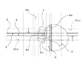
また、ナット部材7は、図3及び図4に示すように、長板状に形成し、短辺7x,7xの寸法LxをC形チャンネル部4の開口幅の寸法Lcよりも短く選定するとともに、長辺7y,7yの寸法LyをC形チャンネル部4の壁部4w,4wにより回り止めされる長さに選定する。この場合、ナット部材7における二つの角部には、ボルト部材6を締め付け方向に回した際に、ナット部材7が回転し、図4に示す仮想線のように、ナット部材7の短辺7x,7xをC形チャンネル部4の壁部4w,4wに当接(係合)させる1/4円弧によるアール部7r,7rを形成する。ボルト部材6及びナット部材7をこのように構成することにより、本実施形態に係る施工方法に用いて最適な固定具5を容易に得ることができる。   Further, as shown in FIGS. 3 and 4, the nut member 7 is formed in a long plate shape, and the dimension Lx of the short sides 7x and 7x is selected to be shorter than the dimension Lc of the opening width of the C-shaped channel portion 4. The dimension Ly of the long sides 7y, 7y is selected to be a length that prevents rotation by the wall portions 4w, 4w of the C-shaped channel portion 4. In this case, at the two corners of the nut member 7, when the bolt member 6 is turned in the tightening direction, the nut member 7 is rotated, and the short side 7x of the nut member 7 as shown by an imaginary line shown in FIG. , 7x are formed into rounded portions 7r, 7r by 1/4 arcs that abut (engage) the wall portions 4w, 4w of the C-shaped channel portion 4. By configuring the bolt member 6 and the nut member 7 in this way, the optimum fixture 5 can be easily obtained by using the construction method according to the present embodiment.

次に、本実施形態に係るウッドデッキDの施工方法について、図1〜図6を参照して説明する。   Next, the construction method of the wood deck D which concerns on this embodiment is demonstrated with reference to FIGS.

施工に際しては、必要数量のデッキ材2…,根太材3…及び固定具5…を用意する。そして、最初に、住宅や施設に備えるベランダやテラス等の施工面Fに、複数の根太材3…を所定間隔おきに設置する。図6は、根太材3…の設置間隔を示している。なお、根太材3…は、施工面Fに対して直接固定してもよいし、他の固定部材等を用いて固定してもよい。また、施工面Fに対して必ずしも固定することを要せず、他の固定手段により固定してもよい。   At the time of construction, a necessary quantity of deck material 2... Joist material 3. First, a plurality of joists 3 are installed at predetermined intervals on a construction surface F such as a veranda or a terrace provided in a house or facility. FIG. 6 shows an installation interval of the joists 3. The joists 3 may be directly fixed to the construction surface F, or may be fixed using another fixing member or the like. Moreover, it does not necessarily require fixing with respect to the construction surface F, and may be fixed by other fixing means.

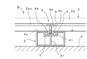
次いで、図6に示すように、各根太材3…の上面3u…に、複数のデッキ材2…を交差(直交)するように並べて配列させるとともに、各デッキ材2…間であって各根太材3…が配された位置に固定具5…を介在させる。この場合、固定具5…は、ボルト部材6…の先端にナット部材7…を仮固定する程度に螺着させた後、図2に示すように、ナット部材7…を根太材3…のC形チャンネル部4に上方から収容するとともに、ボルト部材6…を手で回すことにより高さを調整し、係止頭部6h…をデッキ材2…のスリット2a…に収容する。この結果、当該ボルト部材6…の係止頭部6h…は、相隣るデッキ材2…のスリット2b…にも収容可能となる。   Next, as shown in FIG. 6, a plurality of deck materials 2 are arranged side by side so as to intersect (orthogonally) on the upper surface 3 u of each joist material 3. Fixing tools 5 are interposed at positions where the materials 3 are arranged. In this case, after the fixing members 5 are screwed to the tips of the bolt members 6 so that the nut members 7 are temporarily fixed, the nut members 7 are connected to the joists 3 as shown in FIG. While being accommodated in the channel portion 4 from above, the height is adjusted by manually turning the bolt members 6... And the locking heads 6 h are accommodated in the slits 2 a of the deck material 2. As a result, the locking heads 6h of the bolt members 6 can be accommodated in the slits 2b of the deck materials 2 adjacent to each other.

一方、デッキ材2…をある程度の数量、例えば、10枚程度配列させたなら、最後に配したデッキ材2を押して各デッキ材2…を詰める。そして、この状態において固定具5…の締め付けを行う。この場合、図1に示すように、六角レンチ(回し工具)Tを、各デッキ材2…同士間の隙間Sに上から挿入するとともに、六角レンチTの先端を、ボルト部材6…の六角孔(工具係止部)6s…に差し込み、この後、六角レンチTを締め付ける方向に回し操作すればよい。この際、ナット部材7…は、六角レンチTの回し方向に回転しようとするも、図4に実線で示す位置において壁部4w,4w…に係止するため、C形チャンネル部4…による回り止めが行われる。これにより、ボルト部材6…とナット部材7…による締め付けが可能となり、デッキ材2…は根太材3…に固定される。なお、ボルト部材6…の係止頭部6h…は、円盤状に形成するため、図6に示す部分拡大図のように、各デッキ材2…を千鳥状に配した場合には、三枚のデッキ材2…を同時に固定することができる。したがって、配列形態によっては、四枚のデッキ材2…を同時に固定することも可能である。   On the other hand, when a certain amount of the deck materials 2 are arranged, for example, about 10 pieces, the deck material 2 arranged last is pushed to pack each deck material 2. In this state, the fixtures 5 are tightened. In this case, as shown in FIG. 1, a hexagon wrench (turning tool) T is inserted into the gap S between the deck materials 2 from above, and the tip of the hexagon wrench T is inserted into the hexagon hole of the bolt member 6. (Tool locking part) 6s... Is inserted, and then the hexagon wrench T is turned in the tightening direction. At this time, the nut members 7 are rotated by the C-shaped channel portion 4 because they are locked to the wall portions 4w, 4w at the position indicated by the solid line in FIG. Stop is done. As a result, the bolt members 6 and the nut members 7 can be fastened, and the deck members 2 are fixed to the joists 3. Since the locking heads 6h of the bolt members 6 are formed in a disc shape, three pieces are provided when the deck members 2 are arranged in a staggered manner as shown in the partial enlarged view of FIG. Can be fixed simultaneously. Accordingly, depending on the arrangement form, it is possible to fix the four deck members 2.

以上の作業を繰り返すとともに、必要な仕上処理、例えば、各デッキ材2…の中空部2s…が露出する面を覆うなどの仕上処理を行うことにより、本実施形態に係る施工方法によるウッドデッキD(図6)が得られる。   While repeating the above operations, necessary finishing processing, for example, finishing processing such as covering the surface where the hollow portions 2s of the deck materials 2 are exposed, makes it possible to perform the wood deck D ( FIG. 6) is obtained.

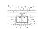
他方、図7及び図8には変更実施形態を示す。この変更実施形態は、図8に示すように、根太材3…を、ベース部11b…及びこのベース部11b…から上方に起立して当該根太材3…の側面を挟持する一対のブラケット部11s,11s…を有する根太材支持部材11…により支持するとともに、ボルト部材6…の係止頭部6h…とデッキ材2…のスリット2as,2bs…間に、ボルト部材6…が挿通する挿通孔12s…を有し、かつ全体を矩形状に形成した押え用ワッシャ部材12…を介在させたものである。   On the other hand, FIGS. 7 and 8 show a modified embodiment. In this modified embodiment, as shown in FIG. 8, a pair of bracket portions 11 s that hold the joist members 3... Upward from the base portion 11 b and the base portions 11 b and sandwich the side surfaces of the joist members 3. , 11s... Are inserted, and bolt members 6 are inserted between the locking heads 6h of the bolt members 6 and the slits 2as, 2bs of the deck members 2. This is a presser washer member 12, which has 12 s... And has a rectangular shape as a whole.

この場合、根太材支持部材11…は、アルミニウム材,スチール材,プラスチック材等の硬質素材により一体形成できる。また、根太材支持部材11…のベース部11b…は、根太材3…よりも広幅に形成する。これにより、根太材3…、更にはデッキ材2…を安定に支持できる。そして、根太材支持部材11…により根太材3…を支持する際は、根太材3…を一対のブラケット部11s,11s…間に挟み込み、設定した高さにおいて固定ネジ16,16…により各ブラケット部11s,11s…を根太材3…の側面に固定する。これにより、排水性のある傾斜した施工面Fに対する根太材3…の高さを任意に調整できるなど、デッキ材2…の水平性及び安定性を容易に確保できる。なお、根太材支持部材11を施工面Fに設置する際は、図8に示すように、防水保護用のゴムシート15を介在させてもよい。これにより、更なる安定性及び衝撃吸収性を確保することができる。   In this case, the joist support members 11 can be integrally formed of a hard material such as an aluminum material, a steel material, or a plastic material. Further, the base portions 11b of the joist support members 11 are formed wider than the joists 3. Thereby, the joists 3... And the deck materials 2 can be stably supported. Then, when the joist members 3 are supported by the joist support members 11, the joists 3 are sandwiched between the pair of bracket portions 11 s, 11 s, and the brackets are fixed by the fixing screws 16, 16, at the set height. The parts 11s, 11s... Are fixed to the side surfaces of the joists 3. Thereby, the levelness and stability of the deck materials 2 can be easily secured, for example, the height of the joists 3 to the inclined construction surface F having drainage can be arbitrarily adjusted. When the joist support member 11 is installed on the construction surface F, as shown in FIG. 8, a rubber sheet 15 for waterproof protection may be interposed. Thereby, further stability and shock absorption can be ensured.

一方、押え用ワッシャ部材12…は、図7に抽出して示すように、全体を矩形状(長方形状)に形成し、中央に挿通孔12s…を設けたものである。これにより、例えば、図7に示すように、デッキ材2…を千鳥状に配するとともに、デッキ材2…における相対向する短辺同士間に隙間Ss…を空けて配した場合であっても、同時に複数のデッキ材2…の隅部を確実かつ安定に保持(固定)できる。なお、隙間Ss…は、温度差などによるデッキ材2…の伸縮を吸収するために設けたものである。その他、図7及び図8において、図1〜図6と同一部分には同一符号を付してその構成を明確にした。   On the other hand, as shown in FIG. 7, the washer members 12 for pressing are formed in a rectangular shape (rectangular shape) as a whole and provided with an insertion hole 12s in the center. Thus, for example, as shown in FIG. 7, even when the deck materials 2 are arranged in a staggered manner and the gaps Ss are arranged between the opposing short sides of the deck materials 2. At the same time, the corners of the plurality of deck materials 2 can be reliably and stably held (fixed). The gaps Ss are provided to absorb expansion and contraction of the deck material 2 due to a temperature difference or the like. In addition, in FIG.7 and FIG.8, the same code | symbol was attached | subjected to the same part as FIGS. 1-6, and the structure was clarified.

よって、このような本実施形態(変更実施形態)に係るウッドデッキDの施工方法によれば、基本的な手法として、上面3u…の長手方向にC形チャンネル部4…を有する複数の根太材3…と、側面2a,2b…の長手方向にスリット2as,2bs…を有する複数のデッキ材2…と、スリット2as,2bs…に差し込み可能な係止頭部6h…を有するボルト部材6…、及びこのボルト部材6…に螺合するとともに、C形チャンネル部4…に収容し、かつ当該C形チャンネル部4…により回り止めされるナット部材7…からなる複数の固定具5…とを用意し、施工面Fに対して根太材3…を所定間隔おきに配するとともに、根太材3…の上面3u…にデッキ材2…を交差するように並べて配し、C形チャンネル部4に収容したナット部材7…に対して、スリット2as,2bs…に係止頭部6h…を差し込んだボルト部材6…を螺着することによりデッキ材2…を根太材3…に固定するようにしたため、デッキ材2…における幅方向の両側を根太材3…に対して固定でき、施工後における全体の強度及び剛性を高めることができる。したがって、衝撃や長期使用等によりガタツキが生じにくく、耐久性を高めることができる。   Therefore, according to the construction method of the wood deck D according to the present embodiment (modified embodiment), a plurality of joists 3 having C-shaped channel portions 4 in the longitudinal direction of the upper surface 3u as a basic method. ..., a plurality of deck members 2 having slits 2as, 2bs ... in the longitudinal direction of the side faces 2a, 2b ..., bolt members 6 ... having locking heads 6h that can be inserted into the slits 2as, 2bs, ... A plurality of fasteners 5 are prepared, which are screwed into the bolt members 6 and housed in the C-shaped channel portions 4 and made of nut members 7 that are prevented from rotating by the C-shaped channel portions 4. The joists 3 are arranged at predetermined intervals with respect to the construction surface F, and the deck members 2 are arranged so as to intersect the upper surfaces 3u of the joists 3 so as to be accommodated in the C-shaped channel portion 4. Nut member 7 On the other hand, since the deck members 2 are fixed to the joists 3 by screwing the bolt members 6 with the locking heads 6h inserted into the slits 2as, 2bs,. Both sides in the width direction can be fixed to the joists 3... And the overall strength and rigidity after construction can be increased. Therefore, rattling is less likely to occur due to impact or long-term use, and durability can be enhanced.

また、複数のデッキ材2…をまとめて配列させ、この後、固定具5…により固定することができるため、施工時間の短縮及び手間の軽減を図れ、能率的な施工を実現できる。しかも、デッキ材2…の位置ずれが他のデッキ材2…に影響しにくくなることから、高品質のウッドデッキDを得ることができる。さらに、部分的なデッキ材2…を破損や汚れ等により交換する場合であっても、該当するデッキ材2…のみを交換できるため、交換作業の著しい容易化を実現できるとともに、他の部品や材料を傷める虞れも回避され、メンテナンス性を高めることができる。   Further, since a plurality of deck materials 2 can be arranged together and thereafter fixed by the fixtures 5..., Construction time can be shortened and labor can be reduced, and efficient construction can be realized. In addition, since the misalignment of the deck materials 2 is less likely to affect the other deck materials 2, a high-quality wood deck D can be obtained. Further, even when the partial deck material 2 is replaced due to damage or dirt, only the corresponding deck material 2 can be replaced, so that the replacement work can be significantly facilitated and other parts and The possibility of damaging the material is also avoided, and the maintainability can be improved.

以上、最良の実施形態について詳細に説明したが、本発明は、このような実施形態に限定されるものではなく、細部の構成,形状,素材,数量等において、本発明の要旨を逸脱しない範囲で、任意に変更,追加,削除することができる。   Although the best embodiment has been described in detail above, the present invention is not limited to such an embodiment, and the scope of the present invention is not deviated from the gist of the present invention in the detailed configuration, shape, material, quantity, and the like. It can be changed, added, or deleted arbitrarily.

例えば、ウッドデッキDは、例示以外の各種用途のウッドデッキに適用できる。また、根太材3は、アルミニウム材等の硬質素材により一体成形した場合を示したが、C形チャンネル部4のみをアルミニウム材等により形成し、このC形チャンネル部4を、木材等により形成した根太材3本体の上に固定するなどの構成であってもよい。さらに、デッキ材2は、リサイクル合成材Rを用いた場合を示したが、天然木材やプラスチック材等の他の素材により形成したデッキ材2であってもよい。一方、回し工具Tとして六角レンチを例示したが、プラスドライバ,マイナスドライバ等の他の回し工具Tであってもよく、ボルト部材6には、これらに対応した工具係止部6sを設けることができる。   For example, the wood deck D can be applied to a wood deck for various uses other than those illustrated. Moreover, the joist 3 is shown as a case of being integrally formed of a hard material such as an aluminum material, but only the C-shaped channel portion 4 is formed of an aluminum material or the like, and the C-shaped channel portion 4 is formed of wood or the like. The structure of fixing on the joist 3 main body may be sufficient. Furthermore, although the case where the recycled synthetic material R was used was shown as the deck material 2, the deck material 2 formed with other raw materials, such as natural wood and a plastic material, may be sufficient. On the other hand, the hexagon wrench is exemplified as the turning tool T, but other turning tools T such as a plus driver and a minus driver may be used, and the bolt member 6 may be provided with a tool locking portion 6s corresponding thereto. it can.

本発明の最良の実施形態に係る施工方法により設置したウッドデッキの断面正面図、A cross-sectional front view of a wood deck installed by a construction method according to the best embodiment of the present invention, 同施工方法により設置したウッドデッキの断面側面図、Cross-sectional side view of a wood deck installed by the same construction method, 同施工方法に用いる固定具(ボルト部材,ナット部材)の正面図、Front view of fixtures (bolt members, nut members) used in the construction method, 同施工方法に用いる固定具の平面図、A plan view of a fixture used in the construction method, 同固定具の施工時における状態を示す平面図、A plan view showing a state during construction of the fixture, 同施工方法により設置したウッドデッキの平面図、Plan view of the wood deck installed by the same construction method, 本発明の変更実施形態に係る施工方法により設置した押え用ワッシャ部材の斜視図を含むウッドデッキの一部平面図、A partial plan view of a wood deck including a perspective view of a washer member for pressing installed by a construction method according to a modified embodiment of the present invention, 同施工方法により設置したウッドデッキの断面側面図、Cross-sectional side view of a wood deck installed by the same construction method, 本発明の実施形態に係る施工方法に用いるデッキ材と根太材の斜視図、The perspective view of the deck material and joist used for the construction method concerning the embodiment of the present invention, 従来技術に係るウッドデッキの施工方法の説明図、Explanatory drawing of the construction method of the wood deck according to the prior art,

符号の説明Explanation of symbols

2 デッキ材
2a デッキ材の側面(一方の側面)
2b デッキ材の側面(他方の側面)
2as スリット
2bs スリット
3 根太材
3u 根太材の上面
4 C形チャンネル部
4i 凹部
4w C形チャンネル部の壁部
5 固定具
6 ボルト部材
6h 係止頭部
6s 工具係止部
7 ナット部材
7x ナット部材の短辺
7y ナット部材の長辺
11 根太材支持部材
11b ベース部
11s ブラケット部
12 押え用ワッシャ部材
12s 挿通孔
D ウッドデッキ
F 施工面
R リサイクル合成材
T 回し工具
Lx 短辺の寸法
Ly 長辺の寸法
Lc 開口幅の寸法
2 Deck material 2a Side surface of deck material (one side surface)
2b Side of deck material (the other side)
2as slit 2bs slit 3 joist member 3u upper surface of joist member 4 C-shaped channel part 4i recessed part 4w wall part of C-shaped channel part 5 fixing tool 6 bolt member 6h locking head 6s tool locking part 7 nut member 7x of nut member Short side 7y Long side of nut member 11 joist support member 11b base part 11s bracket part 12 presser washer member 12s insertion hole D wood deck F construction surface R recycled synthetic material T turning tool Lx short side dimension Ly long side dimension Lc Opening width dimension

Claims (7)

複数のデッキ材を所定の施工面に並べて設置するウッドデッキの施工方法において、上面の長手方向にC形チャンネル部を有する複数の根太材と、側面の長手方向にスリットを有する複数のデッキ材と、前記スリットに差し込み可能な係止頭部を有するボルト部材、及びこのボルト部材に螺合するとともに、前記C形チャンネル部に収容し、かつ当該C形チャンネル部により回り止めされるナット部材からなる複数の固定具とを用意し、前記施工面に対して前記根太材を所定間隔おきに配するとともに、前記根太材の上面に前記デッキ材を交差するように並べて配し、前記C形チャンネル部に収容した前記ナット部材に対して、前記スリットに係止頭部を差し込んだ前記ボルト部材を螺着することにより前記デッキ材を前記根太材に固定することを特徴とするウッドデッキの施工方法。   In the construction method of a wood deck in which a plurality of deck materials are arranged side by side on a predetermined construction surface, a plurality of joists having a C-shaped channel portion in the longitudinal direction of the upper surface, and a plurality of deck materials having slits in the longitudinal direction of the side surfaces; A bolt member having a locking head that can be inserted into the slit, and a plurality of nut members that are screwed into the bolt member, are accommodated in the C-shaped channel portion, and are prevented from rotating by the C-shaped channel portion. And fixing the joist material to the construction surface at predetermined intervals, arranging the deck material so as to intersect the upper surface of the joist material, The deck member is fixed to the joist member by screwing the bolt member with the locking head inserted into the slit to the nut member accommodated. Wood deck method of construction which is characterized the door. 前記根太材は、アルミニウム材等の硬質素材により角パイプ状に形成するとともに、上面に凹部を用いたC形チャンネル部を一体に形成してなることを特徴とする請求項1記載のウッドデッキの施工方法。   2. The wood deck construction according to claim 1, wherein the joist is formed in a square pipe shape by a hard material such as an aluminum material, and a C-shaped channel portion using a concave portion is integrally formed on the upper surface. Method. 前記根太材は、ベース部及びこのベース部から上方に起立して当該根太材の側面を挟持する一対のブラケット部を有する根太材支持部材により支持することを特徴とする請求項1又は2記載のウッドデッキの施工方法。   The said joist material is supported by the joist material support member which has a pair of bracket part which stands up upwards from this base part, and clamps the side surface of the said joist material. Wood deck construction method. 前記デッキ材は、所定量の廃木材と所定量の廃プラスチックを原料とするリサイクル合成材により矩形ボード状に形成してなることを特徴とする請求項1記載のウッドデッキの施工方法。   2. The method for constructing a wood deck according to claim 1, wherein the deck material is formed in a rectangular board shape from a recycled synthetic material made from a predetermined amount of waste wood and a predetermined amount of waste plastic. 前記ボルト部材は、円盤状に形成した係止頭部を有するとともに、この係止頭部の上面中央に、回し工具が係止する工具係止部を有することを特徴とする請求項1記載のウッドデッキの施工方法。   2. The bolt member according to claim 1, wherein the bolt member has a locking head formed in a disc shape, and a tool locking portion for locking the turning tool at the center of the upper surface of the locking head. Wood deck construction method. 前記ボルト部材の係止頭部と前記デッキ材のスリット間には、前記ボルト部材が挿通する挿通孔を有し、かつ全体を矩形状に形成した押え用ワッシャ部材を介在させることを特徴とする請求項1又は5記載のウッドデッキの施工方法。   Between the locking head of the bolt member and the slit of the deck material, there is an insertion hole through which the bolt member is inserted, and a presser washer member formed entirely in a rectangular shape is interposed. The construction method of the wood deck of Claim 1 or 5. 前記ナット部材は、長板状に形成し、短辺の寸法を前記C形チャンネル部の開口幅の寸法よりも短く選定するとともに、長辺の寸法を前記C形チャンネル部の壁部により回り止めされる長さに選定することを特徴とする請求項1記載のウッドデッキの施工方法。   The nut member is formed in a long plate shape, and the short side dimension is selected to be shorter than the opening width dimension of the C-shaped channel part, and the long side dimension is prevented from rotating by the wall part of the C-shaped channel part. The construction method of the wood deck according to claim 1, wherein the length is selected.
JP2005170486A 2004-12-28 2005-06-10 Construction method of wood deck Pending JP2006207363A (en)

Priority Applications (1)

Application Number Priority Date Filing Date Title
JP2005170486A JP2006207363A (en) 2004-12-28 2005-06-10 Construction method of wood deck

Applications Claiming Priority (2)

Application Number Priority Date Filing Date Title
JP2004380547 2004-12-28
JP2005170486A JP2006207363A (en) 2004-12-28 2005-06-10 Construction method of wood deck

Publications (1)

Publication Number Publication Date
JP2006207363A true JP2006207363A (en) 2006-08-10

Family

ID=36964512

Family Applications (1)

Application Number Title Priority Date Filing Date
JP2005170486A Pending JP2006207363A (en) 2004-12-28 2005-06-10 Construction method of wood deck

Country Status (1)

Country Link
JP (1) JP2006207363A (en)

Cited By (12)

* Cited by examiner, † Cited by third party
Publication number Priority date Publication date Assignee Title
JP2008307766A (en) * 2007-06-14 2008-12-25 Misawa Homes Co Ltd Surface improving apparatus
DE102010015281A1 (en) 2010-04-15 2011-10-20 Tobias Wagner Floor system for installation of terrace floors, has connectors forming releasable connection between construction and lining elements, where connection is made with lower side of lining elements that is made of wood-based materials
CN102383575A (en) * 2011-11-23 2012-03-21 李渊 Veneer laying structure
DE102011101567A1 (en) * 2011-05-16 2012-11-22 Markus Rensburg Device for construction of planar surface e.g. terrace surface, on unfinished floor, has clamping device comprising holder unit connected with sub-construction, where clamping device is rotatable in sub-construction around axle of connector
JP2014238160A (en) * 2013-06-07 2014-12-18 株式会社共栄金物製作所 Fastener
DE202013010369U1 (en) * 2013-11-19 2015-02-20 Hans Dieter Grotefeld Mounting element for planks, tiles or the like
EP2275613B1 (en) * 2009-07-16 2019-01-16 Pinufin Oberflächentechnik GmbH & Co. KG Cladding composed of profile elements
CN109790721A (en) * 2016-09-28 2019-05-21 艾德克有限公司 Can Fast Installation and removal Level tune clad structure
IT201900021711A1 (en) * 2019-11-20 2020-02-20 Pontarolo Eng Spa SYSTEM FOR FIXING SLATS.
WO2020216971A1 (en) * 2019-04-26 2020-10-29 Octaedro Innovaciones Constructivas, S.L. Point anchor for construction plates
KR102188413B1 (en) * 2020-02-17 2020-12-08 자연과빛 주식회사 Easy installation Deck plate assembly
KR102540716B1 (en) * 2023-01-26 2023-06-08 아이앤지산업(주) Deck road using joists that can be reused without damage

Cited By (16)

* Cited by examiner, † Cited by third party
Publication number Priority date Publication date Assignee Title
JP4559450B2 (en) * 2007-06-14 2010-10-06 ミサワホーム株式会社 Surface improvement device
JP2008307766A (en) * 2007-06-14 2008-12-25 Misawa Homes Co Ltd Surface improving apparatus
EP2275613B1 (en) * 2009-07-16 2019-01-16 Pinufin Oberflächentechnik GmbH & Co. KG Cladding composed of profile elements
DE102010015281B4 (en) 2010-04-15 2018-07-26 Tobias Wagner Method for laying a floor system
DE102010015281A1 (en) 2010-04-15 2011-10-20 Tobias Wagner Floor system for installation of terrace floors, has connectors forming releasable connection between construction and lining elements, where connection is made with lower side of lining elements that is made of wood-based materials
DE102011101567A1 (en) * 2011-05-16 2012-11-22 Markus Rensburg Device for construction of planar surface e.g. terrace surface, on unfinished floor, has clamping device comprising holder unit connected with sub-construction, where clamping device is rotatable in sub-construction around axle of connector
CN102383575A (en) * 2011-11-23 2012-03-21 李渊 Veneer laying structure
JP2014238160A (en) * 2013-06-07 2014-12-18 株式会社共栄金物製作所 Fastener
DE202013010369U1 (en) * 2013-11-19 2015-02-20 Hans Dieter Grotefeld Mounting element for planks, tiles or the like
CN109790721A (en) * 2016-09-28 2019-05-21 艾德克有限公司 Can Fast Installation and removal Level tune clad structure
WO2020216971A1 (en) * 2019-04-26 2020-10-29 Octaedro Innovaciones Constructivas, S.L. Point anchor for construction plates
IT201900021711A1 (en) * 2019-11-20 2020-02-20 Pontarolo Eng Spa SYSTEM FOR FIXING SLATS.
WO2021100002A1 (en) * 2019-11-20 2021-05-27 Pontarolo Engineering S.P.A. System for fastening slats
CN114466963A (en) * 2019-11-20 2022-05-10 庞塔罗工程有限公司 System for fastening panels
KR102188413B1 (en) * 2020-02-17 2020-12-08 자연과빛 주식회사 Easy installation Deck plate assembly
KR102540716B1 (en) * 2023-01-26 2023-06-08 아이앤지산업(주) Deck road using joists that can be reused without damage

Similar Documents

Publication Publication Date Title
JP2006207363A (en) Construction method of wood deck
JP4268157B2 (en) Floor structure, terrace deck and joist with engagement tool
WO2003102325A3 (en) Wooden structural element and kit for erecting building walls by means of wooden structural elements
KR200449646Y1 (en) A prefabricated pillar for structure
KR200462075Y1 (en) A prefabricated pillar using timber and metal together
KR200396804Y1 (en) Deck system for floor
JP2005344371A (en) Floor structure and terrace deck
KR20170090536A (en) C type fixture used for wall mold and eco mold incorporating the same
JP5440475B2 (en) Panel mounting bracket for projecting corner and panel mounting structure for projecting corner
JP7476127B2 (en) Beam support structure and beam support method
KR200254601Y1 (en) Construction panel structure
KR200439457Y1 (en) Sectional partition
JPH0349001Y2 (en)
JP6591371B2 (en) Shelf for shelf
JP2007113190A (en) Double floor structure and floor panel for use in it
KR200265937Y1 (en) outer panel for wood house wall
KR200323398Y1 (en) a subsidiary window frame
KR100481791B1 (en) Concrete form panel
JP5918677B2 (en) Roof structure
JPS5840167Y2 (en) Connection structure on balcony
KR200285316Y1 (en) Concrete form panel
JP2954467B2 (en) Connecting structure of balcony wall panels
JP2005320775A (en) Stairs
JPH11159110A (en) Coupling metal fitting between floor joist and flooring material, method for laying flooring material, and floor structure
JPH082259Y2 (en) Fixing device for horizontal grounding bodies in partitions, etc.