JP2006206111A - Pouch container - Google Patents
Pouch container Download PDFInfo
- Publication number
- JP2006206111A JP2006206111A JP2005021265A JP2005021265A JP2006206111A JP 2006206111 A JP2006206111 A JP 2006206111A JP 2005021265 A JP2005021265 A JP 2005021265A JP 2005021265 A JP2005021265 A JP 2005021265A JP 2006206111 A JP2006206111 A JP 2006206111A
- Authority
- JP
- Japan
- Prior art keywords
- pouch
- spout
- container
- pouch container
- pouch body
- Prior art date
- Legal status (The legal status is an assumption and is not a legal conclusion. Google has not performed a legal analysis and makes no representation as to the accuracy of the status listed.)
- Pending
Links
Images


Abstract
Description
この発明は、例えば、トイレ洗浄剤、洗剤、シャンプー等の液体商品が充填されるパウチ容器、特に、左右一対のサイドシールを有するボトムガセットタイプのパウチ本体の一方の前記サイドシール部分に注出口部が設けられた、自立性を備えたパウチ容器に関する。 The present invention is, for example, a pouch container filled with liquid commodities such as toilet cleaners, detergents, shampoos, etc., in particular, a spout portion on one side seal portion of a bottom gusset type pouch body having a pair of left and right side seals. It is related with the pouch container provided with independence.
トイレ洗浄剤、洗剤、シャンプー等の液体商品は、ボトル容器等に充填された状態で販売されていたが、ボトル容器等の有効利用を図るために、近年では、シャンプー等の液体商品を簡易なパウチ容器に充填した詰替用の液体商品が販売されている。 Liquid products such as toilet cleaners, detergents, and shampoos were sold in the state of being filled in bottle containers, but in recent years, liquid products such as shampoos have been simplified for effective use of bottle containers. Liquid goods for refilling filled in pouch containers are sold.
従って、消費者は、最初はボトル容器等に充填された液体商品を購入することになるが、この液体商品を使い切った場合は、ボトル容器等に充填された液体商品を新たに購入するのではなく、簡易なパウチ容器に充填された同じ商品である詰替用の液体商品を購入し、空になったボトル容器等に液体商品だけを詰め替えるようになってきている。 Therefore, the consumer first purchases the liquid product filled in the bottle container or the like. However, if the liquid product is used up, the consumer does not purchase a new liquid product filled in the bottle container or the like. Instead, a liquid product for refill, which is the same product filled in a simple pouch container, is purchased, and only the liquid product is refilled into an empty bottle container or the like.
こういった詰替用の液体商品を充填するパウチ容器としては、例えば、図7に示すようなものがある。このパウチ容器50は、同図に示すように、表裏一対の外装シート52、52の下端部からガセットシート53が内側に折り込まれ、そのガセットシート53の周縁部が外装シート52、52にヒートシールされると共に、ガセットシート53に重なっていない外装シート52、52の周縁部が相互にヒートシールされることによって袋状に形成されたパウチ本体51と、このパウチ本体51の上縁部に装着された、スクリューキャップによって開閉可能なスパウト54とを備えている。
An example of such a pouch container filled with liquid goods for refilling is as shown in FIG. In this
ところで、こういったパウチ容器50に充填された液体商品をボトル容器等に詰め替える場合は、図8に示すように、スパウト54をボトル容器の口部に嵌入した状態で、パウチ容器50を上下反転させなければならず、作業性が悪いといった問題があるので、近年では、図9(a)、(b)に示すように、スパウト54をパウチ本体51の上縁シール部分ではなく、サイドシール部分に装着したパウチ容器50Aが望まれている。なお、同図(b)における網掛け表示領域がヒートシール領域を示している。
By the way, when refilling a liquid product filled in such a
上述したように、サイドシール部分にスパウト54が装着されたパウチ容器50Aでは、充填された液体商品をボトル容器等に詰め替える際、上下反転させる必要がなく、横に傾けるだけでよいので、注出作業性はよいが、パウチ容器50A内に充填された液体商品が一部パウチ本体51内に残ってしまい、液体商品を完全に注出することができないといった問題がある。
As described above, in the
そこで、この発明の課題は、液体内容物の注出作業性に優れ、しかも、液体内容物を完全に注出することができるパウチ容器を提供することにある。 Therefore, an object of the present invention is to provide a pouch container that is excellent in the workability of pouring out the liquid contents and that can completely pour out the liquid contents.
上記の課題を解決するため、請求項1にかかる発明は、左右一対のサイドシールを有するボトムガセットタイプのパウチ本体の一方の前記サイドシール部分に注出口部が設けられた、自立性を備えたパウチ容器において、前記パウチ本体における一方の前記サイドシールの内縁は、前記注出口部から前記パウチ本体の底部側に向かって、他方の前記サイドシール側に徐々に近づいていることを特徴とするパウチ容器を提供するものである。
In order to solve the above problems, the invention according to
また、請求項2にかかる発明は、請求項1にかかる発明のパウチ容器において、前記パウチ本体における左右一対のサイドシールの外縁を内側に湾曲させることによって、前記パウチ本体の胴部にくびれを設けたのである。 According to a second aspect of the present invention, in the pouch container according to the first aspect of the present invention, a constriction is provided in the body of the pouch body by curving the outer edges of the pair of left and right side seals in the pouch body inward. It was.
以上のように、請求項1にかかる発明のパウチ容器では、パウチ本体における注出口部が設けられている一方のサイドシールの内縁が、その注出口部からパウチ本体の底部側に向かって、他方のサイドシール側に徐々に近づいているので、注出口部が下を向くように、このパウチ容器を真横に傾けると、注出口部が設けられている一方のサイドシールの内縁が、その注出口部からパウチ本体の底部側に向かって徐々に高くなっている。従って、このパウチ容器に充填された液体内容物を他の容器等に移し替える際、このパウチ容器では、底部側を必要以上に持ち上げなくても、真横に傾けるだけで、充填された液体内容物を完全に注出することができる。 As described above, in the pouch container according to the first aspect of the present invention, the inner edge of one side seal provided with the spout portion in the pouch body is directed from the spout portion toward the bottom side of the pouch body. Since the pouch container is tilted to the side so that the spout portion faces downward, the inner edge of one side seal where the spout portion is provided becomes the spout. It gradually becomes higher from the part toward the bottom side of the pouch body. Therefore, when the liquid content filled in this pouch container is transferred to another container etc., the liquid content filled in this pouch container can be simply tilted sideways without lifting the bottom side more than necessary. Can be completely dispensed.
また、請求項2にかかる発明のパウチ容器では、パウチ本体における左右一対のサイドシールの外縁を内側に湾曲させることによって、パウチ本体の胴部にくびれを設けてあるので、パウチ容器の胴部を手で掴み易くなり、パウチ容器の取扱性が向上する。 Further, in the pouch container according to the second aspect of the present invention, the outer edge of the pair of left and right side seals in the pouch body is curved inward so that the body part of the pouch body is constricted. It becomes easier to grasp by hand and the handling of the pouch container is improved.
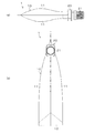
以下、実施の形態について図面を参照して説明する。図1〜図3に示すように、このパウチ容器1は、トイレ洗浄剤、洗剤、シャンプー等の液体や流動体の内容物を充填するものであり、直鎖状低密度ポリエチレン(LLDPE)等の熱接着性を有するシーラントフィルムの外面に、ポリアミドフィルム及びポリエチレンテレフタレートフィルムを積層した厚さ100〜150μm程度の柔軟性シートによって形成された、自立性を有するボトムガセットタイプのパウチ本体10と、このパウチ本体10における一方の側縁に装着される熱接着性樹脂によって形成された、スクリューキャップ21によって開閉可能なスパウト20とから構成されている。
Hereinafter, embodiments will be described with reference to the drawings. As shown in FIGS. 1 to 3, the
前記パウチ本体10は、図2及び図3に示すように、略長方形状の表裏一対の外装シート11、11と、この外装シート11、11の下端部において両者の間に折り込まれるガセットシート12とから構成されており、外装シート11、11の上縁部及び両側縁部が相互にヒートシールされることによって胴部が形成されると共に、外装シート11、11間に折り込まれたガセットシート12の周縁が外装シート11、11の内面にヒートシールされることによってボトムガセット部が形成されている。また、ガセットシート12の両側縁には、二つ折りした状態で相互に一致する切欠部12aがそれぞれ形成されており、この切欠部12aを介して、外装シート11、11の両側縁における下端部同士が部分的にヒートシールされている。なお、図3における網掛け表示領域がヒートシール領域を示している。
2 and 3, the
外装シート11は、パウチ本体10の胴部にくびれが形成されるように、両側縁の高さ方向の中央部を内側に湾曲させてあるが、両湾曲部11a、11bは対称形ではなく、パウチ本体10の胴部を手で掴んだときに手にフィットするように、非対称に形成されている。
The
また、パウチ本体10におけるスパウト20が装着される一方のサイドシールSSaの内縁は、スパウト20の装着位置からパウチ本体10のボトムガセット部に向かって、他方のサイドシールSSb側に徐々に近づいており、図4に示すように、スパウト20の注出口が下を向くように、このパウチ容器1を真横(パウチ本体10の底側外縁が垂直方向を向く状態)に傾けると、パウチ本体10におけるスパウト20が装着されている一方のサイドシールSSaの内縁は、そのボトムガセット側がスパウト装着位置に対して、Δh(=約5mm)だけ高くなっている。
Further, the inner edge of one side seal SSa to which the
また、サイドシールSSaの外縁は、図3に示すように、湾曲部11aを除いて、スパウト20の装着位置とボトムガセット部の形成位置とが同一の垂直線L上にあり、外装シート11の幅が、上部と下部で同一であるので、図5(a)に示すように、ボトムガセット部におけるサイドシールSSaのシール幅が広く形成されており、このパウチ容器1に内容物を充填したときのパウチ本体10における底部の横幅W1と、同図(b)に示すように、サイドシールSSaのシール幅が上下で同一になるように、外装シート11の下部の幅を狭めたパウチ容器に内容物を充填したときのパウチ本体10aにおける底部の横幅W2とを比較すると、W1>W2となり、自立安定性が低下することもない。
Further, as shown in FIG. 3, the outer edge of the side seal SSa is on the same vertical line L with the
以上のように、このパウチ容器1では、スパウト20の注出口が下を向くように、このパウチ容器1を真横に傾けると、パウチ本体10におけるスパウト20が装着されている一方のサイドシールSSaの内縁は、そのボトムガセット側がスパウト装着位置に対して、Δh(=約5mm)だけ高くなっているので、このパウチ容器1に充填された液体内容物を他の容器等に移し替える際、このパウチ容器1では、底部側を必要以上に持ち上げなくても、真横に傾けるだけで、充填された液体内容物を完全に注出することができ、液体内容物の注出作業性がよい。
As described above, in this
また、このパウチ容器1では、パウチ本体10の胴部を手で掴んだときに手にフィットするように、パウチ本体10における左右一対のサイドシールSSa、SSbの外縁を内側に湾曲させることによって、パウチ本体10の胴部に非対称のくびれを設けてあるので、パウチ本体10の胴部を手で掴み易くなり、パウチ容器1の取扱性もよい。しかも、底部の横幅W1が狭くならないため、自立安定性が低下することもない。
Further, in this
なお、上述した実施形態では、パウチ本体10の胴部を手で掴み易くするために、パウチ本体10の両側縁に非対称の湾曲部11a、11bを設けているが、これに限定されるものではなく、両湾曲部は対称であってもよく、図6に示すパウチ容器1Aのように、必ずしも、湾曲部を設ける必要はない。このように、湾曲部を設けない場合であっても、液体内容物の良好な注出作業性を確保するためには、パウチ本体10Aにおけるスパウト20が装着される一方のサイドシールSSaの内縁が、スパウト20の装着位置からパウチ本体10Aのボトムガセット部に向かって、他方のサイドシールSSb側に徐々に近づくようにしておく必要があることはいうまでもない。
In the above-described embodiment, in order to make it easier to grasp the body portion of the
また、上述した実施形態では、注出口部として、スクリューキャップ21によって開閉可能なスパウト20を採用しているが、これに限定されるものではなく、鋏等によって切除することで開封するノズル状の注出口部を採用することも可能である。
Moreover, in embodiment mentioned above, although the
また、上述した各実施形態では、パウチ本体10、10a、10Aを形成する際に使用する2枚の外装シート11、11及びガセットシート12が、それぞれ分離されている場合について説明したが、これに限定されるものではなく、2枚の外装シートとその間に位置するガセットシートとが相互に繋がった状態の1枚のシートを使用することも可能である。
In each of the above-described embodiments, the case where the two
また、上述した実施形態では、詰替用のパウチ容器について説明したが、これに限定されるものではなく、本発明は、様々な用途に使用されるパウチ容器について適用することができることはいうまでもない。 In the above-described embodiment, the refill pouch container has been described. However, the present invention is not limited to this, and the present invention can be applied to pouch containers used for various purposes. Nor.
1、1A パウチ容器
10、10a、10A パウチ本体
11 外装シート
11a、11b 湾曲部
12 ガセットシート
12a 切欠部
20 スパウト
21 スクリューキャップ
SSa、SSb サイドシール
DESCRIPTION OF
Claims (2)
前記パウチ本体における一方の前記サイドシールの内縁は、前記注出口部から前記パウチ本体の底部側に向かって、他方の前記サイドシール側に徐々に近づいていることを特徴とするパウチ容器。 In a pouch container having a self-supporting property, a spout portion is provided in one side seal portion of a bottom gusset type pouch body having a pair of left and right side seals.
An inner edge of one of the side seals in the pouch body gradually approaches the other side seal side from the spout portion toward the bottom side of the pouch body.
Priority Applications (1)
| Application Number | Priority Date | Filing Date | Title |
|---|---|---|---|
| JP2005021265A JP2006206111A (en) | 2005-01-28 | 2005-01-28 | Pouch container |
Applications Claiming Priority (1)
| Application Number | Priority Date | Filing Date | Title |
|---|---|---|---|
| JP2005021265A JP2006206111A (en) | 2005-01-28 | 2005-01-28 | Pouch container |
Publications (1)
| Publication Number | Publication Date |
|---|---|
| JP2006206111A true JP2006206111A (en) | 2006-08-10 |
Family
ID=36963387
Family Applications (1)
| Application Number | Title | Priority Date | Filing Date |
|---|---|---|---|
| JP2005021265A Pending JP2006206111A (en) | 2005-01-28 | 2005-01-28 | Pouch container |
Country Status (1)
| Country | Link |
|---|---|
| JP (1) | JP2006206111A (en) |
Cited By (5)
| Publication number | Priority date | Publication date | Assignee | Title |
|---|---|---|---|---|
| WO2015146205A1 (en) * | 2014-03-28 | 2015-10-01 | 株式会社フジシール | Package material for pouch container and pouch container manufacturing method |
| WO2016080419A1 (en) * | 2014-11-18 | 2016-05-26 | 株式会社明治 | Sealed container for liquid emulsion and liquid emulsion product |
| JP2018172173A (en) * | 2017-03-31 | 2018-11-08 | 大日本印刷株式会社 | Cooking pouch |
| JP2020175930A (en) * | 2019-04-19 | 2020-10-29 | 東洋製罐株式会社 | Refill pouch, and setting method for mounting angle of cylindrical port part of refill pouch |
| JP2023078504A (en) * | 2021-11-26 | 2023-06-07 | 東洋製罐株式会社 | pouch with spout |
-
2005
- 2005-01-28 JP JP2005021265A patent/JP2006206111A/en active Pending
Cited By (8)
| Publication number | Priority date | Publication date | Assignee | Title |
|---|---|---|---|---|
| WO2015146205A1 (en) * | 2014-03-28 | 2015-10-01 | 株式会社フジシール | Package material for pouch container and pouch container manufacturing method |
| JPWO2015146205A1 (en) * | 2014-03-28 | 2017-04-13 | 株式会社フジシール | Pouch container packaging material and method for manufacturing pouch container |
| WO2016080419A1 (en) * | 2014-11-18 | 2016-05-26 | 株式会社明治 | Sealed container for liquid emulsion and liquid emulsion product |
| JPWO2016080419A1 (en) * | 2014-11-18 | 2017-08-24 | 株式会社明治 | Liquid emulsion enclosure and liquid emulsion product |
| JP2018172173A (en) * | 2017-03-31 | 2018-11-08 | 大日本印刷株式会社 | Cooking pouch |
| JP2020175930A (en) * | 2019-04-19 | 2020-10-29 | 東洋製罐株式会社 | Refill pouch, and setting method for mounting angle of cylindrical port part of refill pouch |
| JP7310256B2 (en) | 2019-04-19 | 2023-07-19 | 東洋製罐株式会社 | Refill pouch and method of setting the mounting angle of the mouth of the refill pouch |
| JP2023078504A (en) * | 2021-11-26 | 2023-06-07 | 東洋製罐株式会社 | pouch with spout |
Similar Documents
| Publication | Publication Date | Title |
|---|---|---|
| JPH10101095A (en) | Gusset bag | |
| CZ20021491A3 (en) | Re-sealable container with a pouring orifice | |
| JP2008018991A (en) | Spout of flexible packaging bag | |
| JP5138238B2 (en) | Pouch container | |
| JP2006206111A (en) | Pouch container | |
| JP4913743B2 (en) | Pouch container with spout and method for producing the same | |
| JP4011597B2 (en) | Easy tearable liquid storage bag | |
| US7036713B2 (en) | Tetrahedron/pentahedron container | |
| JP2017210257A (en) | Gazette bag with spout tool | |
| JP3997717B2 (en) | Self-supporting refill container | |
| JP5332450B2 (en) | Pouch container | |
| JP2012176782A (en) | Pouch container | |
| JP2012140145A (en) | Soft package gusset bag container | |
| JP2007331767A (en) | Flexible bag | |
| JPH11236053A (en) | Refill bag | |
| JP2000296859A (en) | Liquid packaging container | |
| JP6659999B2 (en) | Pouch with spout | |
| JP4734853B2 (en) | Standing pouch with handle | |
| JP4263640B2 (en) | Thin container | |
| JP2011178404A (en) | Reclosable back-sealed flat pouch | |
| JP2018070245A (en) | Pouch with bung hole | |
| JP6126411B2 (en) | Packaging bag | |
| JP2008013196A (en) | Refill bag | |
| JP4526829B2 (en) | Pouch container | |
| JP2005059928A (en) | Pouch container |