JP2006205013A - Apparatus for electrostatic aerification - Google Patents

Apparatus for electrostatic aerification Download PDF

Info

Publication number
JP2006205013A
JP2006205013A JP2005018682A JP2005018682A JP2006205013A JP 2006205013 A JP2006205013 A JP 2006205013A JP 2005018682 A JP2005018682 A JP 2005018682A JP 2005018682 A JP2005018682 A JP 2005018682A JP 2006205013 A JP2006205013 A JP 2006205013A
Authority
JP
Japan
Prior art keywords
discharge electrode
electrode
electrostatic atomizer
discharge
electrostatic
Prior art date
Legal status (The legal status is an assumption and is not a legal conclusion. Google has not performed a legal analysis and makes no representation as to the accuracy of the status listed.)
Granted
Application number
JP2005018682A
Other languages
Japanese (ja)
Other versions
JP4442444B2 (en
Inventor
Kentaro Kobayashi
健太郎 小林
Shinya Murase
慎也 村瀬
Koichi Hirai
康一 平井
Akihide Sugawa
晃秀 須川
Fumio Mihara
史生 三原
Junji Imai
順二 今井
Toshihisa Hirai
利久 平井
Current Assignee (The listed assignees may be inaccurate. Google has not performed a legal analysis and makes no representation or warranty as to the accuracy of the list.)
Panasonic Electric Works Co Ltd
Original Assignee
Matsushita Electric Works Ltd
Priority date (The priority date is an assumption and is not a legal conclusion. Google has not performed a legal analysis and makes no representation as to the accuracy of the date listed.)
Filing date
Publication date
Priority to JP2005018682A priority Critical patent/JP4442444B2/en
Application filed by Matsushita Electric Works Ltd filed Critical Matsushita Electric Works Ltd
Priority to US11/547,132 priority patent/US7874503B2/en
Priority to PCT/JP2005/006496 priority patent/WO2005097338A1/en
Priority to EP05727279A priority patent/EP1733797B8/en
Priority to AT05727279T priority patent/ATE419922T1/en
Priority to DE602005012248T priority patent/DE602005012248D1/en
Priority to TW094111259A priority patent/TWI252783B/en
Publication of JP2006205013A publication Critical patent/JP2006205013A/en
Priority to HK07107448.6A priority patent/HK1103048A1/en
Application granted granted Critical
Publication of JP4442444B2 publication Critical patent/JP4442444B2/en
Expired - Fee Related legal-status Critical Current
Anticipated expiration legal-status Critical

Links

Images

Abstract

<P>PROBLEM TO BE SOLVED: To provide an apparatus for electrostatic aerification by condensation of moisture which is capable of simultaneously and stably releasing ionic mist from each discharge electrode part and of increasing the amount of ionic mist. <P>SOLUTION: The electrostatic aerification apparatus 2 dews the moisture in air by cooling the discharge electrode part 1 to produce water by moisture condensation at the discharge electrode part 1 and spreads the above water to air as ionic mist by electrostatic aerification. The electrostatic aerification apparatus 2 is composed of two or more of discharge electrode parts 1, an endothermic body 3 to cool theses discharge electrode parts 1 and a counter electrode part 4. The cooling temperature at the end part of an electrode bar 5 to form each the discharge electrode part 1 is almost the same. The electric field strength at the end part of the electrode bar 5 to form each discharge electrode part 1 at the time of high voltage application is almost the same. <P>COPYRIGHT: (C)2006,JPO&NCIPI

Description

本発明は、静電霧化現象によりナノメータサイズのイオンミストを発生させる静電霧化装置に関するものである。   The present invention relates to an electrostatic atomizer that generates nanometer-sized ion mist by an electrostatic atomization phenomenon.

従来から放電電極部と、放電電極部に対向して位置する対向電極部と、放電電極部に水を供給する供給手段とを備え、放電電極部と対向電極部との間に高電圧を印加することで放電電極部に保持される水を霧化させ、イオンミストを発生させる静電霧化装置が、特許文献1により知られている。   Conventionally, a discharge electrode part, a counter electrode part positioned opposite the discharge electrode part, and a supply means for supplying water to the discharge electrode part are provided, and a high voltage is applied between the discharge electrode part and the counter electrode part. Patent Document 1 discloses an electrostatic atomizer that atomizes water held in a discharge electrode portion to generate ion mist.

しかしながら、上記特許文献1に示された従来の静電霧化装置は、貯水部に溜めた水を毛細管現象を利用して放電電極部の先端まで搬送するようにした吸い上げ式の静電霧化装置であり、使用者は貯水部内の水が無くなれば、順次継ぎ足していかねばならないという煩わしさがあり、使い勝手が悪いという問題があった。また、上記の静電霧化装置においては、供給する水が水道水のようなCa、Mg等の不純物を含む水であった場合、この不純物が空気中のCOと反応して水搬送部の先端部にCaCOやMgO等を析出付着させ、毛細管現象による水の供給を阻害し、また不純物が毛細管に詰まり、これらの理由によりイオンミストの発生を妨げるという問題があった。 However, the conventional electrostatic atomizer shown in the above-mentioned patent document 1 is a suction type electrostatic atomizer in which the water accumulated in the water reservoir is transported to the tip of the discharge electrode using the capillary phenomenon. This is a device, and there is a problem that the user has a trouble of having to add one after another if the water in the water storage part runs out, which is inconvenient. Further, in the above electrostatic atomizer, when the water to be supplied is water containing impurities such as Ca and Mg such as tap water, the impurities react with CO 2 in the air and the water transport unit CaCO 3 , MgO, or the like is deposited on the tip of the glass, obstructing the supply of water due to capillary action, and clogging the capillaries, which prevents the generation of ion mist for these reasons.

そこで、上記問題を解決するために、本発明者は本発明に到る過程で、吸熱体により空気を冷却して、空気中の水分を結露させて結露水を生成し、それを放電電極部まで供給するか、あるいは、空気中の水分を冷却して放電電極部に直接結露させて放電電極部に結露水を生成させ、放電電極部で生成された結露水を静電霧化により空気中にイオンミストとして発散させる結露式の静電霧化装置を開発した。   Therefore, in order to solve the above problem, in the course of reaching the present invention, the inventor cools the air by the endothermic body to condense moisture in the air to generate dew condensation water, which is used as the discharge electrode unit. Or the moisture in the air is cooled and condensed directly on the discharge electrode part to generate condensed water on the discharge electrode part, and the condensed water generated on the discharge electrode part is formed in the air by electrostatic atomization. Has developed a condensation-type electrostatic atomizer that emits ion mist.

ところが、この結露式の静電霧化装置においては放電電極部が1つしかなく、放出イオンミスト量も限界があり、放出量を増加させるには上記静電霧化装置を複数個使用して動作させる必要があり、コストが高くなると共に、装置全体が大型化するという問題があった。   However, this dew condensation type electrostatic atomizer has only one discharge electrode part, and the amount of released ion mist is limited. To increase the amount of discharge, a plurality of electrostatic atomizers are used. There is a problem that it is necessary to operate the apparatus, and the cost is increased and the entire apparatus is enlarged.

また、貯水部に溜めた水を吸い上げる吸い上げ式の静電霧化装置においては、放電電極部を複数設け、貯水部から複数の放電電極部にそれぞれ水を搬送し、放出イオンミスト量を増加させる技術が従来から行われているが、結露式の静電霧化装置においては、ただ単純に放電電極部を増やしただけでは、イオンミスト量の増大を図ることができない。   Also, in the suction type electrostatic atomizer that sucks up the water stored in the water storage part, a plurality of discharge electrode parts are provided, and water is transferred from the water storage part to the plurality of discharge electrode parts, respectively, thereby increasing the amount of released ion mist. Although the technology has been conventionally used, in a dew condensation type electrostatic atomizer, the amount of ion mist cannot be increased simply by increasing the number of discharge electrodes.

なぜならば、結露式の静電霧化装置においては、安定したイオンミスト放出を実現させるには、結露水の生成量、放電の条件(放電付近の電界強度、電気力線)等を厳しく管理し、それを長時間維持することが必要である。すなわち、各々の放電電極部における結露水の生成量や、各々の放電電極部における放電条件にわずかなずれが存在すると、ある放電電極部からは安定したイオンミストが発生していても、他の放電電極部では、結露水の多過、あるいは不足、放電電界強度が強過ぎる、あるいは放電電界強度が弱過ぎる等の状態が起こり、イオンミスト放出が行われないといった現象が生じることが判明した。
特許第3260150号公報
This is because in a condensation-type electrostatic atomizer, in order to achieve stable ion mist emission, the amount of condensed water produced, the conditions of discharge (electric field strength near the discharge, electric lines of force), etc. are strictly controlled. It is necessary to maintain it for a long time. That is, if there is a slight deviation in the amount of condensed water produced in each discharge electrode part and the discharge conditions in each discharge electrode part, even if stable ion mist is generated from a certain discharge electrode part, In the discharge electrode portion, it has been found that a phenomenon such as excessive or insufficient dew condensation water, a discharge electric field intensity that is too strong, or a discharge electric field intensity that is too weak occurs, and ion mist emission is not performed.
Japanese Patent No. 3260150

本発明は上記の従来の問題点に鑑みて発明したものであって、結露式の静電霧化装置において各放電電極部からのイオンミストの放出を同時に且つ安定して行え、各放電電極部を冷却するための電力量を殆ど変えることなく、イオンミスト量の増大を図ることができるようにすることを課題とするものである。   The present invention was invented in view of the above-described conventional problems, and in a dew condensation type electrostatic atomizer, discharge of ion mist from each discharge electrode portion can be performed simultaneously and stably. An object of the present invention is to increase the amount of ion mist without changing the amount of power for cooling the battery.

上記課題を解決するために本発明に係る静電霧化装置は、放電電極部1を冷却して空気中の水分を結露させて放電電極部1に結露水を生成し、該結露水を静電霧化により空気中にイオンミストとして発散させる静電霧化装置2であって、2つ以上の放電電極部1と、これらの放電電極部1を冷却するための吸熱体3と、対向電極部4とから構成され、それぞれの放電電極部1となる電極棒5の先端部の冷却温度がほぼ同一で且つ高電圧印加時のそれぞれの放電電極部1となる電極棒5の先端部の電界強度がほぼ同一になるように構成されたことを特徴とするものである。   In order to solve the above problems, the electrostatic atomizer according to the present invention cools the discharge electrode unit 1 to condense moisture in the air to generate condensed water in the discharge electrode unit 1, and An electrostatic atomizing device 2 that diverges as ion mist in the air by electroatomization, comprising two or more discharge electrode portions 1, a heat absorber 3 for cooling these discharge electrode portions 1, and a counter electrode And the electric field at the tip of each electrode rod 5 that becomes the respective discharge electrode portion 1 when a high voltage is applied. It is characterized in that the strength is substantially the same.

このような構成とすることで、結露式の静電霧化装置2において、2つ以上の放電電極部1からのイオンミストの放出を同時に且つ安定して行うことができるものであり、吸熱体3からの吸熱量、すなわち各放電電極部1を冷却するための電力量を殆ど変えることなく、生成されるイオンミスト量が増加し、これに伴って付着脱臭性能、アレルゲン物質の除去性能、除菌性能が向上するものであり、また、結露式の静電霧化装置2において、イオンミスト量を増加するに当たって、複数の静電霧化装置を複数使用して動作させるものに比べて装置サイズが大型化せず、コンパクト化が図れる。   By adopting such a configuration, in the dew condensation type electrostatic atomizer 2, the ion mist can be discharged simultaneously from two or more discharge electrode portions 1, and the heat absorber. 3, that is, the amount of generated ion mist increases without substantially changing the amount of power for cooling each discharge electrode portion 1, and accompanying this, the adhesion deodorization performance, allergen substance removal performance, removal Bacteria performance is improved, and in the dew condensation type electrostatic atomizer 2, the device size is larger than that operated by using a plurality of electrostatic atomizers when increasing the amount of ion mist. Can be made compact without increasing the size.

また、2つ以上の電極棒5が、吸熱体3により冷却される基部6から2つ以上の放電電極部1に至る経路を分岐した経路により構成してあることが好ましい。   Further, it is preferable that the two or more electrode rods 5 are constituted by paths that branch from the base 6 cooled by the heat absorber 3 to the two or more discharge electrode parts 1.

このような構成とすることで、吸熱体3により吸熱して冷却される基部6が共通であるため、2つ以上の電極棒5を均一に冷却して各電極棒5の先端部の放電電極部1の冷却温度を容易に揃えることができる。   With such a configuration, since the base 6 that is absorbed by the heat absorber 3 and cooled is common, two or more electrode rods 5 are uniformly cooled, and the discharge electrode at the tip of each electrode rod 5 is discharged. The cooling temperature of the part 1 can be easily aligned.

また、すべての放電電極部1の先端形状が等しく且つすべての放電電極部1から対向電極部4までの距離を等しく設定することが好ましい。   Moreover, it is preferable that the tip shapes of all the discharge electrode portions 1 are equal and the distances from all the discharge electrode portions 1 to the counter electrode portions 4 are set equal.

このような構成とすることで、容易に各放電電極部1の電界強度を高精度で揃えることができる。   By setting it as such a structure, the electric field strength of each discharge electrode part 1 can be arrange | equalized with high precision easily.

また、電極棒5を構成する部分が同一材料で、各電極棒5が基部6からの分岐点7に対して対称に配置してあることが好ましい。   Further, it is preferable that the portions constituting the electrode rod 5 are made of the same material, and each electrode rod 5 is arranged symmetrically with respect to the branch point 7 from the base portion 6.

このような構成とすることで、各電極棒5の先端部の放電電極部1の温度を高精度で揃えることができる。   By setting it as such a structure, the temperature of the discharge electrode part 1 of the front-end | tip part of each electrode stick | rod 5 can be arrange | equalized with high precision.

また、電極棒5に通電を行うための電気的接続を分岐部8よりも基部6側において行うことが好ましい。   Moreover, it is preferable to make electrical connection for energizing the electrode rod 5 on the base 6 side with respect to the branch portion 8.

このような構成とすることで、各電極棒5の先端部の放電電極部1の温度バランスを崩すことなく、高電圧印加のための電気的接続ができる。   With such a configuration, an electrical connection for applying a high voltage can be achieved without breaking the temperature balance of the discharge electrode portion 1 at the tip of each electrode bar 5.

また、分岐部8から電極棒5の根元までのすべて又は一部を断熱材9により覆うことが好ましい。   Further, it is preferable to cover all or a part from the branching portion 8 to the base of the electrode rod 5 with the heat insulating material 9.

このような構成とすることで、霧化に関与しない余剰結露水の生成を抑制できる。   By setting it as such a structure, the production | generation of the surplus dew condensation water which does not participate in atomization can be suppressed.

また、各放電電極部1に対してそれぞれ同一の対向電極部4を、各電極棒5に対して同一の位置関係となるように配置することが好ましい。   In addition, it is preferable that the same counter electrode part 4 is arranged with respect to each discharge electrode part 1 so as to have the same positional relationship with respect to each electrode bar 5.

このような構成とすることで、各放電電極部1の電界強度を高精度で揃え、且つイオンミストの発生効率を最大限にできる。   With such a configuration, the electric field strengths of the respective discharge electrode portions 1 can be aligned with high accuracy, and ion mist generation efficiency can be maximized.

本発明は、結露式の静電霧化装置において、2つ以上の放電電極部からのイオンミストの放出を同時に且つ安定して行い、各放電電極部を冷却するための電力量を殆ど変えることなく、生成されるイオンミスト量を増加できて付着脱臭性能、アレルゲン物質の除去性能、除菌性能を向上でき、更に、結露式の静電霧化装置において、イオンミスト量を増加できるようにしたものにおいて装置サイズが大型化せず、コンパクト化が図れる。   According to the present invention, in a dew condensation type electrostatic atomizer, the discharge of ion mist from two or more discharge electrode portions is performed simultaneously and stably, and the amount of electric power for cooling each discharge electrode portion is almost changed. The amount of generated ion mist can be increased, and the adhesion deodorization performance, allergen substance removal performance and sterilization performance can be improved, and the amount of ion mist can be increased in the condensation type electrostatic atomizer. As a result, the device size is not increased and the device can be made compact.

以下、本発明を添付図面に示す実施形態に基いて説明する。   Hereinafter, the present invention will be described based on embodiments shown in the accompanying drawings.

本発明の静電霧化装置2は、2つ以上の放電電極部1と、これらの放電電極部1を冷却するための吸熱体3と、対向電極部4とで構成してある。放電電極部1を冷却するための吸熱体3としては、ペルチェモジュール10を使用している。   The electrostatic atomizer 2 of the present invention is composed of two or more discharge electrode portions 1, a heat absorber 3 for cooling these discharge electrode portions 1, and a counter electrode portion 4. A Peltier module 10 is used as the heat absorber 3 for cooling the discharge electrode portion 1.

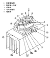
2つ以上の放電電極部1は単一の電極部材11に設けてあり、該電極部材11は吸熱体3により冷却される基部6から分岐部8を介して複数の電極棒5を基部6と反対方向に一体に突設して構成してあり、複数の電極棒5の先端部がそれぞれ放電電極部1となっている。電極部材11の基部6は添付図面に示す実施形態では細首部6bの一端部に細首部6bよりも面積が広い大径底面部6aを設けて構成してあり、細首部6bの大径底面部6aと反対側の端部に分岐部8が設けてある。   Two or more discharge electrode portions 1 are provided on a single electrode member 11, and the electrode member 11 connects a plurality of electrode rods 5 to a base portion 6 through a branch portion 8 from a base portion 6 cooled by an endothermic body 3. A plurality of electrode rods 5 are formed as projecting integrally in the opposite direction. In the embodiment shown in the accompanying drawings, the base portion 6 of the electrode member 11 is formed by providing a large-diameter bottom surface portion 6a having an area larger than that of the narrow neck portion 6b at one end portion of the narrow neck portion 6b. A branch portion 8 is provided at the end opposite to 6a.

ここで、基部6から分岐部8を介して分岐して突設した複数の電極棒5はいずれも基部6からの分岐部8の中心である分岐点7に対して対称(図2の実施形態のように分岐部8を介して2つの電極棒5を分岐して突設した例では2つの電極棒5が180°回転対称となっている。また、分岐部8を介して3つの電極棒5を分岐して突設する場合には3つの電極棒5が互いに120°回転対称となる。)に配置してあり、更に、各電極棒5を構成する部分が同一材料で形成してある。この場合、すべての電極棒5を含む電極部材11全体を同一材料で形成してもよく、すべての電極棒5を同一材料で形成すると共に先端部が分岐部8となった基部6を電極棒5と別部材で形成し、分岐部8に複数の電極棒5を固着したものであってもよい。このように構成することで、複数の電極棒5の各先端部の放電電極部1の熱抵抗を統一させることができ、各放電電極部1の温度分布をほぼ同じにすることができる。これにより装置の寸法を大きくすることなく、複数の放電電極部1を単一の静電霧化装置2に設けることができる。   Here, the plurality of electrode rods 5 that are branched from the base 6 via the branching portion 8 are symmetrical with respect to the branching point 7 that is the center of the branching portion 8 from the base 6 (the embodiment of FIG. 2). In the example in which the two electrode rods 5 are branched and protruded through the branching portion 8 as described above, the two electrode rods 5 are 180 ° rotationally symmetric. When the projection 5 is branched and projected, the three electrode rods 5 are rotationally symmetrical to each other by 120 °. Further, the portions constituting each electrode rod 5 are formed of the same material. . In this case, the entire electrode member 11 including all the electrode bars 5 may be formed of the same material, and all the electrode bars 5 are formed of the same material, and the base 6 having the tip portion formed as the branching portion 8 is used as the electrode rod. 5 may be formed as a separate member, and a plurality of electrode rods 5 may be fixed to the branch portion 8. By comprising in this way, the thermal resistance of the discharge electrode part 1 of each front-end | tip part of the some electrode rod 5 can be unified, and the temperature distribution of each discharge electrode part 1 can be made substantially the same. Thereby, the several discharge electrode part 1 can be provided in the single electrostatic atomizer 2 without enlarging the dimension of an apparatus.

吸熱体3を構成するペルチェモジュール10は、例えば熱伝導性の高いアルミナや窒化アルミニウムからなる絶縁板の片面側に回路を形成してある一対のペルチェ回路板を、互いの回路が向き合うように対向させ、多数列設してあるBiTe系の熱電素子を両ペルチェ回路板間で挟持すると共に隣接する熱電素子同士を両側の回路で電気的に接続させ、ペルチェモジュール10に設けた通電用コネクタ19に接続するペルチェ入力リード線を介してなされる熱電素子への通電により一方のペルチェ回路板側から他方のペルチェ回路板側に向けて熱が移動するように設けたものである。   The Peltier module 10 constituting the heat absorber 3 is formed by facing a pair of Peltier circuit boards having a circuit formed on one side of an insulating plate made of alumina or aluminum nitride having high thermal conductivity so that the circuits face each other. The BiTe-based thermoelectric elements arranged in multiple rows are sandwiched between the two Peltier circuit boards, and the adjacent thermoelectric elements are electrically connected by the circuits on both sides, and the energizing connector 19 provided in the Peltier module 10 is connected to Heat is transferred from one Peltier circuit board side to the other Peltier circuit board side by energization of a thermoelectric element made through a connected Peltier input lead wire.

上記ペルチェモジュール10の冷却側のペルチェ回路板の外側にはアルミナや窒化アルミニウム等からなる高熱伝導性及び高耐電性の高い冷却用絶縁板12を熱伝導性グリース等を介して接続してあり、また、上記他方の側(以下、放熱側という)のペルチェ回路板の外側にはアルミナや窒化アルミニウム等からなる高熱伝導性の放熱部13を熱伝導性グリース等を介して接続してある。放熱部13に放熱フィン部13aが設けてあって電極棒5の冷却を効率よく行えるようにしてある。   The outside of the Peltier circuit board on the cooling side of the Peltier module 10 is connected to a cooling insulating plate 12 made of alumina, aluminum nitride or the like with high thermal conductivity and high electric resistance through thermal conductive grease or the like, In addition, a high heat conductive heat dissipating portion 13 made of alumina, aluminum nitride or the like is connected to the outside of the Peltier circuit board on the other side (hereinafter referred to as the heat radiating side) via a heat conductive grease or the like. The heat dissipating part 13 is provided with a heat dissipating fin part 13a so that the electrode rod 5 can be cooled efficiently.

上記吸熱体3を構成するペルチェモジュール10及び電極部材11はハウジング14内に内装してある。   The Peltier module 10 and the electrode member 11 constituting the heat absorber 3 are housed in the housing 14.

ハウジング14はペルチェ側ハウジング部14aと静電霧化側ハウジング部14bとよりなる。ペルチェモジュール10及び電極部材11の基部6がペルチェ側ハウジング部14a内に内装してあり、ペルチェモジュール10の冷却側に設けた冷却用絶縁板12に電極部材11の基部6の端部の大径底面部6aを面接触させてある。ハウジング14のペルチェ側ハウジング部14aは放熱部13に固着してある。   The housing 14 includes a Peltier side housing part 14a and an electrostatic atomization side housing part 14b. The base 6 of the Peltier module 10 and the electrode member 11 is housed inside the Peltier-side housing portion 14a, and the large diameter of the end of the base 6 of the electrode member 11 is provided on the cooling insulating plate 12 provided on the cooling side of the Peltier module 10. The bottom surface portion 6a is in surface contact. The Peltier side housing portion 14 a of the housing 14 is fixed to the heat radiating portion 13.

ペルチェ側ハウジング部14aと静電霧化側ハウジング部14aとを仕切る仕切り部に設けた孔を電極部材11の基部6の細首部6bが貫通し、静電霧化側ハウジング部14a内に分岐部8及び該分岐部8を介して突出した複数の電極棒5が配置してある。   The narrow neck portion 6b of the base portion 6 of the electrode member 11 passes through a hole provided in a partition portion that partitions the Peltier side housing portion 14a and the electrostatic atomization side housing portion 14a, and branches into the electrostatic atomization side housing portion 14a. 8 and a plurality of electrode rods 5 protruding through the branching portion 8 are arranged.

ここで、各放電電極部1で安定した放電を維持するためには、各電極棒5間の距離を十分にとることが望ましく、5mm以上の距離が好ましい。実施形態では各電極棒5の距離を10mmにしている。   Here, in order to maintain a stable discharge in each discharge electrode portion 1, it is desirable to take a sufficient distance between the electrode rods 5, and a distance of 5 mm or more is preferable. In the embodiment, the distance between the electrode bars 5 is 10 mm.

添付図面に示す実施形態では上記ペルチェ側ハウジング部14aと静電霧化側ハウジング部14bとは別体であって、ペルチェ側ハウジング部14aの上底面部に静電霧化側ハウジング部14bの下底面部を重ねて固着手段により固着してハウジング14を構成してある(この場合、ペルチェ側ハウジング部14aの上底面部に静電霧化側ハウジング部14bの下底面部とで仕切りが構成される)が、ペルチェ側ハウジング部14aと静電霧化側ハウジング部14bとを一体に成形してハウジング14を構成してもよい。   In the embodiment shown in the accompanying drawings, the Peltier-side housing portion 14a and the electrostatic atomizing-side housing portion 14b are separate from each other, and the upper bottom surface portion of the Peltier-side housing portion 14a is below the electrostatic atomizing-side housing portion 14b. The housing 14 is configured by overlapping the bottom surface portions and fixed by the fixing means (in this case, a partition is formed by the upper bottom surface portion of the Peltier side housing portion 14a and the lower bottom surface portion of the electrostatic atomizing side housing portion 14b. However, the Peltier side housing part 14a and the electrostatic atomization side housing part 14b may be integrally formed to form the housing 14.

電極部材11の基部6には通電を行うためのリード板16が電気的に接続してある。このリード板16の電極部材11への接続部は基部6の大径底面部6aと分岐部8との間に位置している。これにより分岐部8から各放電電極部1までの温度分布が等しくなり、各放電電極部1における結露量を等しくすることができる。   A lead plate 16 for energization is electrically connected to the base 6 of the electrode member 11. The connecting portion of the lead plate 16 to the electrode member 11 is located between the large-diameter bottom surface portion 6 a of the base portion 6 and the branch portion 8. Thereby, the temperature distribution from the branch part 8 to each discharge electrode part 1 becomes equal, and the amount of dew condensation in each discharge electrode part 1 can be made equal.

各電極棒5の先端部の各放電電極部1の先端から適当な距離をおいてイオン放出用の開口部17を設けた対向電極部4が設置してあり、この対向電極部4は静電霧化側ハウジング部14bに固定してある。   A counter electrode portion 4 provided with an ion emission opening 17 is provided at an appropriate distance from the tip of each discharge electrode portion 1 at the tip of each electrode rod 5. It is fixed to the atomizing side housing part 14b.

対向電極部4はイオン放出用の開口部17を有する一つの対極板15により構成してあり、それぞれの放電電極部1の先端から対極板15までの距離を等しくしてあり、これにより、並列で各放電電極部1と対向電極部4との間で高電圧を印加して、それぞれの放電部に等しい電界強度、電気力線を生じさせることができるようにしてある。   The counter electrode part 4 is composed of one counter electrode plate 15 having an opening 17 for ion emission, and the distance from the tip of each discharge electrode part 1 to the counter electrode plate 15 is made equal. Thus, a high voltage is applied between each discharge electrode portion 1 and the counter electrode portion 4 to generate electric field strength and electric lines of force equal to the respective discharge portions.

図1乃至図4に示す実施形態では2つの放電電極部1を設けた例であり、一つの対極板15に縁部が対向電極部4となった2つのイオン放出用の開口部17を設け、2つの放電電極部1にそれぞれ2つのイオン放出用の開口部17が対応するように配置してある。ここで2つのイオン放出用の開口部17は同じ径の円孔により構成してあり、各イオン放出用の開口部17の円の中心にそれぞれ各放電電極部1を配置してある。   The embodiment shown in FIGS. 1 to 4 is an example in which two discharge electrode portions 1 are provided, and two counter electrode portions 15 are provided with two ion emission openings 17 on one counter electrode plate 15. The two discharge electrode portions 1 are arranged so as to correspond to the two ion emission openings 17 respectively. Here, the two ion emission openings 17 are formed by circular holes having the same diameter, and the respective discharge electrode portions 1 are arranged at the centers of the circles of the respective ion emission openings 17.

静電霧化側ハウジング部14bの側面には、発生したイオンを効率よく放出するために空気孔18が設けてある。   An air hole 18 is provided on the side surface of the electrostatic atomization side housing portion 14b in order to efficiently discharge the generated ions.

また、図示を省略しているが、放電電極部1側に高電圧を印加する場合、冷却用絶縁板12と電極部材11の周囲を絶縁性の樹脂で封止する必要がある。すなわち、上記のように絶縁性の樹脂で封止することで、高電圧印加時に電極棒5に結露した水によってペルチェモジュール10や放熱フィン部13aへの漏電を防ぐようになっている。   Although not shown, when a high voltage is applied to the discharge electrode portion 1 side, it is necessary to seal the periphery of the cooling insulating plate 12 and the electrode member 11 with an insulating resin. That is, by sealing with an insulating resin as described above, leakage of water to the Peltier module 10 and the heat radiation fin portion 13a due to water condensed on the electrode rod 5 when a high voltage is applied is prevented.

次に各部材の材質につき説明する。電極部材11としては電気伝導性がよく、且つ熱伝導性が高い材質が望ましく、例えば、銅、アルミニウム、銀、あるいはそれらの合金などがよい。冷却用絶縁板12としては熱伝導率が高く、且つ電気絶縁性が高い材質が望ましく、例えば、アルミナや窒化アルミなどの材質がよい。対向電極部4を構成する対極板15としては電気伝導性を有する材質が必要で、電気伝導性を示す金属、樹脂が良く、実施例ではSUSを使用している。ハウジング14は絶縁性を有する材質で、且つ熱損失を防ぐために熱伝導率が低い材質が望ましく、例えば、ABS、PPS、PBTなどの樹脂がよい。放熱フィン部13aを有する放熱部13としては、熱伝導性の高い材質が望ましく、例えば、アルミニウム、銅などがよい。また、封止樹脂としては、エポキシ系樹脂、ポリアミド系樹脂、ウレタン系樹脂等が有効である。   Next, the material of each member will be described. The electrode member 11 is preferably made of a material having good electrical conductivity and high thermal conductivity, such as copper, aluminum, silver, or an alloy thereof. The cooling insulating plate 12 is preferably made of a material having high thermal conductivity and high electrical insulation, and for example, a material such as alumina or aluminum nitride is preferable. The counter electrode plate 15 constituting the counter electrode portion 4 requires a material having electrical conductivity, and is preferably a metal or resin showing electrical conductivity. In the embodiment, SUS is used. The housing 14 is preferably made of an insulating material and has a low thermal conductivity in order to prevent heat loss. For example, a resin such as ABS, PPS, or PBT is preferable. As the heat radiating portion 13 having the heat radiating fin portion 13a, a material having high thermal conductivity is desirable, and for example, aluminum, copper, or the like is preferable. Further, as the sealing resin, epoxy resin, polyamide resin, urethane resin, and the like are effective.

イオンミストを発生させる原理は以下の通りである。まず、ペルチェモジュール10に通電を行い、冷却用絶縁板12と共に複数の電極棒5を有する電極部材11を冷却する。電極棒5が露点温度よりも下回ると空気中の水分が電極棒5に結露し始め、各電極棒5先端部の各放電電極部1に結露水が生成される。このようにして各放電電極部1に結露水が十分に生成されると、各放電電極部1と対向電極部4との間に高電圧を印加する。各放電電極部1と対向電極部4との間に高電圧を印加すると、各放電電極部1の先端部に生成された結露水が帯電し、この帯電した結露水にクーロン力が働き、該結露水が先端が尖った錐状に盛り上がる(テイラーコーン)。この時印加される電圧が水の表面張力を超えて分裂、飛散(レイリー分裂)を起こさせることができる高電圧であれば、放電電極部1に生成した結露水はテイラーコーン形状となってレイリー分裂を起こしてナノメータサイズのイオンミストが発生するという静電霧化がなされ、大気中に放出される。   The principle of generating ion mist is as follows. First, the Peltier module 10 is energized to cool the electrode member 11 having the plurality of electrode bars 5 together with the cooling insulating plate 12. When the electrode rod 5 falls below the dew point temperature, moisture in the air begins to condense on the electrode rod 5, and dew condensation water is generated at each discharge electrode portion 1 at the tip of each electrode rod 5. When the condensed water is sufficiently generated in each discharge electrode portion 1 in this way, a high voltage is applied between each discharge electrode portion 1 and the counter electrode portion 4. When a high voltage is applied between each discharge electrode unit 1 and the counter electrode unit 4, the dew condensation water generated at the tip of each discharge electrode unit 1 is charged, and the Coulomb force acts on the charged dew condensation water, Condensed water rises into a cone with a sharp tip (Taylor Cone). If the voltage applied at this time exceeds the surface tension of water and is a high voltage capable of causing splitting and scattering (Rayleigh splitting), the condensed water generated in the discharge electrode portion 1 becomes a Taylor cone shape and becomes Rayleigh. Electrostatic atomization that causes splitting and generation of nanometer-sized ion mist is performed and released into the atmosphere.

このようにして発生したナノメータサイズのイオンミストは活性種(ヒドロキシラジカル、スパーオキサイド等)を持ったナノメータサイズのイオンミストであるため、これを室内に放出することで、室内の空気の脱臭のみならず、室内壁面や衣類等に付着して壁面や衣類等に付着した臭いを除去することことができ、また、このような付着脱臭性能に加え、更に、アレルゲン除去性能、除菌性能等がある。   The nanometer-sized ion mist generated in this way is a nanometer-sized ion mist with active species (hydroxy radicals, superoxide, etc.). By releasing this into the room, only deodorization of indoor air can be achieved. It is possible to remove odors attached to the wall surface or clothing etc., and in addition to such adhesion deodorizing performance, there are allergen removal performance, sterilization performance, etc. .

この場合、マイナスイオンを含んだミストを放出させるには、対向電極部4を構成する対極板15を接地し、複数の電極棒5を有する電極部材11に負の高電圧を印加するか、あるいは、対向電極部4を構成する対極板15に正の高電圧を印加し、複数の電極棒5を有する電極部材11を接地すればよい。また、プラスイオンを含んだミストを放出させるには、対向電極部4を構成する対極板15を接地し、複数の電極棒5を有する電極部材11に正の高電圧を印加するか、あるいは、対向電極部4を構成する対極板15に負の高電圧を印加し、複数の電極棒5を有する電極部材11を接地すればよい。   In this case, in order to release the mist containing negative ions, the counter electrode plate 15 constituting the counter electrode portion 4 is grounded, and a negative high voltage is applied to the electrode member 11 having the plurality of electrode rods 5, or A positive high voltage may be applied to the counter electrode plate 15 constituting the counter electrode unit 4 to ground the electrode member 11 having the plurality of electrode rods 5. Further, in order to release mist containing positive ions, the counter electrode plate 15 constituting the counter electrode portion 4 is grounded, and a positive high voltage is applied to the electrode member 11 having the plurality of electrode bars 5, or What is necessary is just to apply a negative high voltage to the counter-electrode board 15 which comprises the counter electrode part 4, and to earth | ground the electrode member 11 which has the several electrode rod 5. FIG.

上記においては、図1乃至図4に基づいて放電電極部1を2つ有する静電霧化装置2について説明したが、放電電極部1を3つ以上設けた静電霧化装置2であってもよく、この場合は放出するイオンミスト量は更に増加する。放電電極部1を3つ以上設けた静電霧化装置2の構造は上記した放電電極部1を2つ設けた静電霧化装置2と基本的には同じで、電極部材11の形状、対向電極部4を構成する対極板15の形状、更に、各部材を固定するハウジング14の形状が異なっている。その一例として図5には3つの放電電極部1を有する静電霧化装置2の例が示してあり、この図5に示す実施形態においては、一つの対極板15にそれぞれ縁部が対向電極部4となるイオン放出用の開口部17が3つ設けてあり、この3つの対向電極部4がそれぞれ3つの放電電極部1に対向しており、各対向電極部4から対応する対向電極部4までの距離をそれぞれ等しくしてある。   In the above, although the electrostatic atomizer 2 having two discharge electrode portions 1 has been described based on FIGS. 1 to 4, the electrostatic atomizer 2 having three or more discharge electrode portions 1 is provided. In this case, the amount of released ion mist further increases. The structure of the electrostatic atomizer 2 provided with three or more discharge electrode portions 1 is basically the same as the electrostatic atomizer 2 provided with two discharge electrode portions 1 described above, the shape of the electrode member 11, The shape of the counter electrode plate 15 constituting the counter electrode portion 4 and the shape of the housing 14 for fixing each member are different. As an example, FIG. 5 shows an example of an electrostatic atomizer 2 having three discharge electrode portions 1. In the embodiment shown in FIG. There are provided three ion emission openings 17 serving as the portions 4, and the three counter electrode portions 4 are opposed to the three discharge electrode portions 1, respectively. The distances up to 4 are equal.

上記各実施形態では、各放電電極部1に対向してそれぞれ縁部が対向電極部4となるイオン放出用の開口部17をそれぞれ1つずつ設けた例を示したが、図6、図7に示すように、複数の放電電極部1に対してイオン放出用の開口部17を1つ設け、このイオン放出用の開口部17の円の中心から同心円上に、各放電電極部1を等間隔で配置してもよい。但し、各々の放電電極部1から放出されるイオンミスト発生効率を向上させるには、各放電電極部1に対してそれぞれ1つずつイオン放出用の開口部17を設けた方が望ましい。   In each of the above-described embodiments, an example is shown in which each of the discharge electrode portions 1 is opposed to each discharge electrode portion 1 and each of the opening portions 17 for ion emission whose edge portion becomes the counter electrode portion 4 is provided. As shown in FIG. 1, one ion emission opening 17 is provided for a plurality of discharge electrode parts 1, and each discharge electrode part 1 is arranged concentrically from the center of the circle of the ion emission opening 17. They may be arranged at intervals. However, in order to improve the efficiency of generating ion mist emitted from each discharge electrode portion 1, it is desirable to provide one ion emission opening 17 for each discharge electrode portion 1.

また、図8に示すように、分岐部8から電極棒5の根元までのすべて又は一部を熱伝導性の低い断熱材9により覆ってもよい。これにより、余分な結露水の生成を防ぎ、過剰結露による漏電や、水垂れを防ぐことができる。断熱材9の材質としては、ウレタン樹脂やフェノール樹脂等の樹脂系断熱材や、ガラスウール、セラミックファイバー等の繊維系断熱材、あるいはセラミックを混合した断熱塗料などが有効である。   Moreover, as shown in FIG. 8, you may cover all or one part from the branch part 8 to the base of the electrode stick 5 with the heat insulating material 9 with low heat conductivity. Thereby, generation | occurrence | production of excessive dew condensation water can be prevented, and the electric leakage by excessive dew condensation and water dripping can be prevented. Effective materials for the heat insulating material 9 include resin heat insulating materials such as urethane resin and phenol resin, fiber heat insulating materials such as glass wool and ceramic fibers, and heat insulating paints mixed with ceramic.

図9には放電電極部1を複数設けた場合における微分型静電分級装置(DMA)によって計測した放出イオンミスト量の比較である。各放電電極部1の放電条件を同一にし、約5×10⁷(V/m)の電界強度に調整して、各放電部で安定した静電霧化を行った。この結果により、放電電極部1を増加させると、それに伴って放出されるイオンミスト量も増加していくことがわかる。これにより、付着脱臭性能、アレルゲン除去性能、除菌性能等が向上する。   FIG. 9 is a comparison of the amount of released ion mist measured by a differential electrostatic classifier (DMA) when a plurality of discharge electrode portions 1 are provided. The discharge conditions of each discharge electrode part 1 were made the same, and it adjusted to the electric field strength of about 5 * 107 (V / m), and performed the stable electrostatic atomization in each discharge part. From this result, it can be seen that when the discharge electrode portion 1 is increased, the amount of ion mist released is increased accordingly. Thereby, adhesion deodorization performance, allergen removal performance, sterilization performance, etc. improve.

本発明の静電霧化装置の一実施形態の斜視図である。It is a perspective view of one embodiment of the electrostatic atomizer of the present invention. 同上の平面図である。It is a top view same as the above. 同上の図2のA−A線の断面図である。It is sectional drawing of the AA line of FIG. 2 same as the above. 同上の図2のB−B線の断面図である。It is sectional drawing of the BB line of FIG. 2 same as the above. 本発明の静電霧化装置の他の実施形態の斜視図である。It is a perspective view of other embodiment of the electrostatic atomizer of this invention. 本発明の静電霧化装置の更に他の実施形態の平面図である。It is a top view of other embodiment of the electrostatic atomizer of this invention. 同上の図6のA−A線の断面図である。It is sectional drawing of the AA line of FIG. 6 same as the above. 本発明の静電霧化装置の更に他の実施形態の断面図である。It is sectional drawing of other embodiment of the electrostatic atomizer of this invention. 微分型静電分級装置(DMA)による放出イオン量測定結果を示すグラフである。It is a graph which shows the discharge | release ion amount measurement result by a differential electrostatic classification device (DMA).

符号の説明Explanation of symbols

1 放電電極部
2 静電霧化装置
3 吸熱体
4 対向電極部
5 電極棒
6 基部
7 分岐点
8 分岐部
9 断熱材
DESCRIPTION OF SYMBOLS 1 Discharge electrode part 2 Electrostatic atomizer 3 Endothermic body 4 Counter electrode part 5 Electrode rod 6 Base part 7 Branch point 8 Branch part 9 Thermal insulation

Claims (7)

放電電極部を冷却して空気中の水分を結露させて放電電極部に結露水を生成し、該結露水を静電霧化により空気中にイオンミストとして発散させる静電霧化装置であって、2つ以上の放電電極部と、これらの放電電極部を冷却するための吸熱体と、対向電極部とから構成され、それぞれの放電電極部となる電極棒の先端部の冷却温度がほぼ同一で且つ高電圧印加時のそれぞれの放電電極部となる電極棒の先端部の電界強度がほぼ同一になるように構成されたことを特徴とする静電霧化装置。   An electrostatic atomizer that cools a discharge electrode to condense moisture in the air to generate condensed water in the discharge electrode, and disperses the condensed water as ion mist in the air by electrostatic atomization. Consists of two or more discharge electrode parts, a heat absorber for cooling these discharge electrode parts, and a counter electrode part, and the cooling temperature of the tip part of the electrode rod that becomes each discharge electrode part is substantially the same And the electrostatic atomizer characterized by the electric field strength of the front-end | tip part of the electrode rod used as each discharge electrode part at the time of a high voltage application being substantially the same. 2つ以上の電極棒が、吸熱体により冷却される基部から2つ以上の放電電極部に至る経路を分岐した経路により構成してあることを特徴とする請求項1記載の静電霧化装置。   2. The electrostatic atomizer according to claim 1, wherein the two or more electrode rods are constituted by a path branched from a base part cooled by the endothermic body to the two or more discharge electrode parts. . すべての放電電極部の先端形状が等しく且つすべての放電電極部から対向電極部までの距離を等しく設定して成ることを特徴とする請求項1又は請求項2記載の静電霧化装置。   The electrostatic atomizer according to claim 1 or 2, wherein the tip shapes of all the discharge electrode parts are equal and the distances from all the discharge electrode parts to the counter electrode part are set equal. 電極棒を構成する部分が同一材料で、各電極棒が基部からの分岐点に対して対称に配置してあることを特徴とする請求項2記載の静電霧化装置。   3. The electrostatic atomizer according to claim 2, wherein the portions constituting the electrode rod are made of the same material, and each electrode rod is arranged symmetrically with respect to a branch point from the base portion. 電極棒に通電を行うための電気的接続を分岐部よりも基部側において行うことを特徴とする請求項2又は請求項4記載の静電霧化装置。   5. The electrostatic atomizer according to claim 2, wherein electrical connection for energizing the electrode rod is performed on the base side with respect to the branch portion. 分岐部から電極棒の根元までのすべて又は一部を断熱材により覆って成ることを特徴とする請求項2又は請求項4または請求項5記載の静電霧化装置。   6. The electrostatic atomizer according to claim 2, 4 or 5, wherein all or a part from the branch portion to the base of the electrode rod is covered with a heat insulating material. 各放電電極部に対してそれぞれ同一の対向電極部を、各電極棒に対して同一の位置関係となるように配置して成ることを特徴とする請求項3記載の静電霧化装置。
4. The electrostatic atomizer according to claim 3, wherein the same counter electrode portion is arranged for each discharge electrode portion so as to have the same positional relationship with respect to each electrode rod.
JP2005018682A 2004-04-08 2005-01-26 Electrostatic atomizer Expired - Fee Related JP4442444B2 (en)

Priority Applications (8)

Application Number Priority Date Filing Date Title
JP2005018682A JP4442444B2 (en) 2005-01-26 2005-01-26 Electrostatic atomizer
PCT/JP2005/006496 WO2005097338A1 (en) 2004-04-08 2005-04-01 Electrostatic atomizer
EP05727279A EP1733797B8 (en) 2004-04-08 2005-04-01 Electrostatic atomizer
AT05727279T ATE419922T1 (en) 2004-04-08 2005-04-01 ELECTROSTATIC ATOMIZER
US11/547,132 US7874503B2 (en) 2004-04-08 2005-04-01 Electrostatcially atomizing device
DE602005012248T DE602005012248D1 (en) 2004-04-08 2005-04-01 ELECTROSTATIC SPRAYER
TW094111259A TWI252783B (en) 2004-04-08 2005-04-08 Electrostatic atomizing device
HK07107448.6A HK1103048A1 (en) 2004-04-08 2007-07-12 Electrostatically atomizing device

Applications Claiming Priority (1)

Application Number Priority Date Filing Date Title
JP2005018682A JP4442444B2 (en) 2005-01-26 2005-01-26 Electrostatic atomizer

Related Child Applications (1)

Application Number Title Priority Date Filing Date
JP2009269104A Division JP2010089088A (en) 2009-11-26 2009-11-26 Electrostatic atomizing device

Publications (2)

Publication Number Publication Date
JP2006205013A true JP2006205013A (en) 2006-08-10
JP4442444B2 JP4442444B2 (en) 2010-03-31

Family

ID=36962400

Family Applications (1)

Application Number Title Priority Date Filing Date
JP2005018682A Expired - Fee Related JP4442444B2 (en) 2004-04-08 2005-01-26 Electrostatic atomizer

Country Status (1)

Country Link
JP (1) JP4442444B2 (en)

Cited By (11)

* Cited by examiner, † Cited by third party
Publication number Priority date Publication date Assignee Title
JP2007054808A (en) * 2005-08-26 2007-03-08 Matsushita Electric Works Ltd Electrostatic atomization apparatus
JP2008149243A (en) * 2006-12-15 2008-07-03 Matsushita Electric Works Ltd Electrostatic atomizing apparatus
JP2009045208A (en) * 2007-08-20 2009-03-05 Panasonic Electric Works Co Ltd Electrostatic atomizer and hair dryer having the same
JP2009133609A (en) * 2007-11-06 2009-06-18 Panasonic Corp Refrigerator
JP2010104321A (en) * 2008-10-31 2010-05-13 Iseki & Co Ltd Electrostatic spray apparatus of farm work vehicle
JP2010167418A (en) * 2010-04-05 2010-08-05 Panasonic Electric Works Co Ltd Charge reduction method to electrostatic atomization
JP2011067770A (en) * 2009-09-25 2011-04-07 Panasonic Electric Works Co Ltd Electrostatic atomizer
WO2011121892A1 (en) * 2010-03-29 2011-10-06 パナソニック株式会社 Refrigerator and electrostatic atomization device
WO2014118848A1 (en) * 2013-02-04 2014-08-07 パナソニック株式会社 Electrostatic atomizer
US11498086B2 (en) 2017-05-31 2022-11-15 Leshow Electronic Technology Co. Ltd. Water droplet generating apparatus
US11504726B2 (en) 2017-05-31 2022-11-22 Leshow Electronic Technology Co. Ltd., Hangzhou Water droplet generating apparatus

Cited By (15)

* Cited by examiner, † Cited by third party
Publication number Priority date Publication date Assignee Title
JP2007054808A (en) * 2005-08-26 2007-03-08 Matsushita Electric Works Ltd Electrostatic atomization apparatus
JP4656051B2 (en) * 2006-12-15 2011-03-23 パナソニック電工株式会社 Electrostatic atomizer
JP2008149243A (en) * 2006-12-15 2008-07-03 Matsushita Electric Works Ltd Electrostatic atomizing apparatus
US8235312B2 (en) 2006-12-15 2012-08-07 Panasonic Corporation Electrostatic atomizer
JP2009045208A (en) * 2007-08-20 2009-03-05 Panasonic Electric Works Co Ltd Electrostatic atomizer and hair dryer having the same
JP2009133609A (en) * 2007-11-06 2009-06-18 Panasonic Corp Refrigerator
JP2010104321A (en) * 2008-10-31 2010-05-13 Iseki & Co Ltd Electrostatic spray apparatus of farm work vehicle
JP2011067770A (en) * 2009-09-25 2011-04-07 Panasonic Electric Works Co Ltd Electrostatic atomizer
WO2011121892A1 (en) * 2010-03-29 2011-10-06 パナソニック株式会社 Refrigerator and electrostatic atomization device
JP2011226760A (en) * 2010-03-29 2011-11-10 Panasonic Corp Refrigerator
JP2010167418A (en) * 2010-04-05 2010-08-05 Panasonic Electric Works Co Ltd Charge reduction method to electrostatic atomization
WO2014118848A1 (en) * 2013-02-04 2014-08-07 パナソニック株式会社 Electrostatic atomizer
JP2014147635A (en) * 2013-02-04 2014-08-21 Panasonic Corp Electrostatic atomization device
US11498086B2 (en) 2017-05-31 2022-11-15 Leshow Electronic Technology Co. Ltd. Water droplet generating apparatus
US11504726B2 (en) 2017-05-31 2022-11-22 Leshow Electronic Technology Co. Ltd., Hangzhou Water droplet generating apparatus

Also Published As

Publication number Publication date
JP4442444B2 (en) 2010-03-31

Similar Documents

Publication Publication Date Title
JP4442444B2 (en) Electrostatic atomizer
JP4016934B2 (en) Electrostatic atomizer
JP4449859B2 (en) Electrostatic atomizer
WO2005097338A1 (en) Electrostatic atomizer
JP2006068711A (en) Electrostatic atomizing device
JP2009090192A (en) Electrostatically atomizing device
JP5221942B2 (en) Electrostatic atomizer and dryer
WO2013035453A1 (en) Electrostatic atomizing apparatus
JP2008155144A (en) Electrostatic atomizing device
US20110220322A1 (en) Indoor unit of airconditioner comprising electric discharge generator
JP4670711B2 (en) Electrostatic atomizer
JP3986549B2 (en) Electrostatic atomizer
JP2009045554A (en) Electrostatic atomizing device
JP4305534B2 (en) Electrostatic atomizer
JP2010089088A (en) Electrostatic atomizing device
JP4952294B2 (en) Electrostatic atomizer
WO2012043389A1 (en) Electrostatic atomizing device
JP4036886B2 (en) Electrostatic atomizer
JP2007190086A (en) Blower
JP2008238061A (en) Electrostatic atomizer
JP5342464B2 (en) Electric appliance
JP2009125652A (en) Electrostatic atomizing device and examination system of the device
JP4036887B2 (en) Electrostatic atomizer
JP3986550B2 (en) Electrostatic atomizer
JP4821579B2 (en) Electrostatic atomizer

Legal Events

Date Code Title Description
A621 Written request for application examination

Effective date: 20070119

Free format text: JAPANESE INTERMEDIATE CODE: A621

A131 Notification of reasons for refusal

Effective date: 20090929

Free format text: JAPANESE INTERMEDIATE CODE: A131

A521 Written amendment

Effective date: 20091126

Free format text: JAPANESE INTERMEDIATE CODE: A523

TRDD Decision of grant or rejection written
A01 Written decision to grant a patent or to grant a registration (utility model)

Effective date: 20091222

Free format text: JAPANESE INTERMEDIATE CODE: A01

A01 Written decision to grant a patent or to grant a registration (utility model)

Free format text: JAPANESE INTERMEDIATE CODE: A01

A61 First payment of annual fees (during grant procedure)

Free format text: JAPANESE INTERMEDIATE CODE: A61

Effective date: 20100104

FPAY Renewal fee payment (prs date is renewal date of database)

Year of fee payment: 3

Free format text: PAYMENT UNTIL: 20130122

FPAY Renewal fee payment (prs date is renewal date of database)

Year of fee payment: 4

Free format text: PAYMENT UNTIL: 20140122

LAPS Cancellation because of no payment of annual fees