JP2006202965A - Vaporizing apparatus and vaporizing structure - Google Patents
Vaporizing apparatus and vaporizing structure Download PDFInfo
- Publication number
- JP2006202965A JP2006202965A JP2005012830A JP2005012830A JP2006202965A JP 2006202965 A JP2006202965 A JP 2006202965A JP 2005012830 A JP2005012830 A JP 2005012830A JP 2005012830 A JP2005012830 A JP 2005012830A JP 2006202965 A JP2006202965 A JP 2006202965A
- Authority
- JP
- Japan
- Prior art keywords
- vaporization
- raw material
- vaporizing
- liquid raw
- liquid
- Prior art date
- Legal status (The legal status is an assumption and is not a legal conclusion. Google has not performed a legal analysis and makes no representation as to the accuracy of the status listed.)
- Pending
Links
Images


Abstract
Description
本発明は半導体製造プロセスにおいて使用される液体原料を気体に変換する気化装置であって、キャリアガスをまったく用いないか、或いは極く少量を流す方式の気化装置に関する。 The present invention relates to a vaporizer that converts a liquid material used in a semiconductor manufacturing process into a gas, and relates to a vaporizer that uses no carrier gas or allows a very small amount to flow.
近年、シリコン集積回路素子はその微細化と高集積化の度合いを一段と進めているが、これに合わせて成膜技術も一段と進化している。最近では半導体薄膜の作製プロセスにおいて、TEOSを始めとする液体原料が多用されるようになっているが、それには液体原料を所定量正確に気化させる必要があり、この要求に合わせて現在まで多くの液体原料気化供給システムが商品化されている。しかしながら、これまでの液体原料気化供給システムでは、いずれも液体原料を気化させる際に、多量のキャリアガスを使用している。キャリアガスを使用する理由は、液体原料の気化を容易にすることと、気化装置から例えばCVD装置のような成膜装置へ気化ガスを迅速に搬送することができるようにするためである。このようなものとして、特開2001‐11634[特許文献]に示すような本発明者らによる気化装置がある。 In recent years, the degree of miniaturization and high integration of silicon integrated circuit elements has been further advanced, and the film formation technology has further evolved accordingly. Recently, liquid raw materials such as TEOS are frequently used in the semiconductor thin film manufacturing process, but it is necessary to vaporize the liquid raw material accurately in a predetermined amount. The liquid raw material vaporization supply system has been commercialized. However, all of the conventional liquid material vaporization and supply systems use a large amount of carrier gas when vaporizing the liquid material. The reason for using the carrier gas is to facilitate the vaporization of the liquid raw material and to allow the vaporized gas to be rapidly transferred from the vaporizer to a film forming apparatus such as a CVD apparatus. As such a thing, there exists a vaporization apparatus by the present inventors as shown to Unexamined-Japanese-Patent No. 2001-11634 [patent document].
しかしながら、最近では更なる半導体薄膜の膜特性の向上のためキャリアガスの使用を排除したいとする傾向、並びに、成膜装置の反応室の圧力を低下させたいという要求が強く、そのためには液体原料の気化ガスを搬送するキャリアガスを極力小流量にするか、或いはキャリアガスをゼロ、つまり、キャリアガス・フリーとすることが強く望まれている。また、その供給量もプロセスによって千差万別であり、対応が非常に困難であった。 Recently, however, there is a strong tendency to eliminate the use of carrier gas for further improvement of the film properties of the semiconductor thin film, and there is a strong demand for reducing the pressure in the reaction chamber of the film forming apparatus. It is strongly desired that the carrier gas for transporting the vaporized gas has a flow rate as small as possible, or that the carrier gas is zero, that is, the carrier gas is free. In addition, the amount of supply varies greatly depending on the process, and it was very difficult to cope with it.
本発明の課題は、従来の気化装置では対応できなかった問題点、すなわちキャリアガスを極力小流量にするか、或いはキャリアガス・フリーを達成でき新規な気化装置を提供するにある。 An object of the present invention is to provide a novel vaporizer capable of achieving a problem that cannot be dealt with by a conventional vaporizer, that is, making the carrier gas flow as small as possible, or achieving carrier gas free.
「請求項1」は本発明の気化装置(A)の気化構造に関し「液体原料供給部(1A)から供給された液体原料(L)を加熱して気化させる気化装置(A)の気化部(1B)の気化構造であって、
気化部(1B)内に気化ブロック(2)が収納され、前記気化ブロック(2)との間に間隙(d)が設けられている気化室(3)が形成されており、
気化室(3)の内周面或いは気化ブロック(2)の外周面の少なくともいずれか一方に、気化室に入り込んだ液体原料の流下用の螺旋溝(4)が形成されている」ことを特徴とする。
“
A vaporization block (2) is housed in the vaporization section (1B), and a vaporization chamber (3) provided with a gap (d) between the vaporization block (2) is formed,
A spiral groove (4) for the flow of the liquid material that has entered the vaporization chamber is formed on at least one of the inner peripheral surface of the vaporization chamber (3) and the outer peripheral surface of the vaporization block (2). '' And
「請求項2」は本発明の気化装置(A)の基本形に関し「液体原料(L)を気化部(1B)に供給する液体原料供給部(1A)と、供給された液体原料(L)を加熱して気化させる気化部(1B)と構成された気化装置(A)であって、
気化部(1B)内に気化ブロック(2)が収納され、前記気化ブロック(2)との間に間隙(d)が設けられている気化室(3)が形成されており、
気化室(3)の内周面或いは気化ブロック(2)の外周面の少なくともいずれか一方に、気化室(3)に入り込んだ液体原料の流下用の螺旋溝(4)が形成されている」ことを特徴とする。
“
A vaporization block (2) is housed in the vaporization section (1B), and a vaporization chamber (3) provided with a gap (d) between the vaporization block (2) is formed,
At least one of the inner peripheral surface of the vaporization chamber (3) and the outer peripheral surface of the vaporization block (2) is formed with a spiral groove (4) for flowing down the liquid raw material that has entered the vaporization chamber (3). '' It is characterized by that.
「請求項3」は請求項2に記載の気化装置(A)の変形例で「液体原料供給部(1A)には液体原料供給部(1A)内に残留する液体原料(L)を気化部(1B)に押し出すためのパージ部(1C)が設けられている」ことを特徴とする。
“
気化室(3)内に流入した液体原料(L)は螺旋溝(4)を流下している間に加熱されて次第に蒸発し、原料ガス(G)となって気化部(1B)から成膜装置に供給される。液体原料(L)の流入量が多い場合には、螺旋溝(4)の下端近傍まで流入し、流入量が少ない場合には螺旋溝(4)の入り口付近まで流入した処で蒸発を完了する。即ち、液体原料(L)の流入量に拘らず、その全量をガス化させることができる。ガス化の熱は気化ブロック(2)や気化室(1B)の外周面を構成する気化部本体(1)から供給されるもので、間隙(d)内に流入した液体原料(L)は気化ブロック(2)や気化部本体(1)から供給されてキャリアガス(K)なし或いは極く僅かなキャリアガス(K)の供給で液体原料(L)の蒸発が完了する。原料ガス(G)の大半又は全体が液体原料(L)のガスである。なお、パージ部(1C)を設けることにより、図示しない液体原料質量流量計から供給された液体原料(L)の全量を気化(1B)に供給することができる。 The liquid raw material (L) that has flowed into the vaporization chamber (3) is heated while flowing down the spiral groove (4) and gradually evaporates to form a raw material gas (G), which is formed from the vaporization section (1B). Supplied to the device. When the amount of inflow of the liquid raw material (L) is large, it flows into the vicinity of the lower end of the spiral groove (4), and when the amount of inflow is small, the evaporation is completed when it flows into the vicinity of the entrance of the spiral groove (4). . That is, regardless of the inflow amount of the liquid raw material (L), the entire amount can be gasified. The heat of gasification is supplied from the vaporizer body (1) that constitutes the outer peripheral surface of the vaporization block (2) and vaporization chamber (1B), and the liquid raw material (L) that has flowed into the gap (d) is vaporized. Evaporation of the liquid raw material (L) is completed when the carrier gas (K) is supplied from the block (2) or the vaporizing unit main body (1) without supplying the carrier gas (K) or very little. Most or all of the raw material gas (G) is a liquid raw material (L) gas. By providing the purge unit (1C), the entire amount of the liquid raw material (L) supplied from a liquid raw material mass flow meter (not shown) can be supplied to the vaporization (1B).
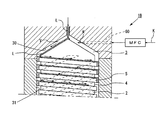
以下、本発明を図示実施例に従って詳述する。図1は本発明に係る気化装置(A)の第1実施例の全体断面図で、大別して液体原料供給部(1A)と気化部(1B)及び両者を連結する液体原料供給導管(9)とで構成され、気化部(1B)の上に図示しない断熱部材を介して液体原料供給部(1A)が載置されている。本発明の変形例としてパージ部(1C)や少量のキャリアガス(K)を供給するキャリアガス供給部(図示せず)を付加したものがあるが、ここではこれらが付属していない基本形のものについて説明し、その後これら変形例について説明する。 Hereinafter, the present invention will be described in detail according to illustrated embodiments. FIG. 1 is an overall cross-sectional view of a first embodiment of a vaporizer (A) according to the present invention, which is roughly divided into a liquid raw material supply section (1A), a vaporization section (1B), and a liquid raw material supply conduit (9) for connecting the two. The liquid material supply unit (1A) is placed on the vaporization unit (1B) via a heat insulating member (not shown). As a modification of the present invention, there is a purge unit (1C) and a carrier gas supply unit (not shown) for supplying a small amount of carrier gas (K), but here they are of a basic type not attached These modifications will be described later.
前記液体原料供給部(1A)は開閉バルブ用駆動素子を収納した開閉バルブ(12)、液体原料流量制御バルブ用駆動素子(13)を収納した液体原料流量制御バルブ(11)及び流量制御弁室(15)を有するバルブ部(14)とで構成され、開閉バルブ用駆動素子を内蔵する開閉バルブ(12)は液体原料流量制御バルブ用駆動素子(13)を内蔵する液体原料流量制御バルブ(11)に直列接続され、液体原料流量制御バルブ(11)の弁体(16)を開閉制御するようになっている。この開閉バルブ(12)に内蔵された開閉バルブ用駆動素子は、空圧駆動(勿論、ソレノイドやモータを利用した電気式でも可)で、その頂部に駆動ガス供給ノズル(12a)が突設されている。 The liquid source supply unit (1A) includes an on-off valve (12) that houses an on-off valve drive element, a liquid source flow control valve (11) that contains a liquid source flow control valve drive element (13), and a flow control valve chamber. And an open / close valve (12) having a valve element (14) having an open / close valve drive element (15) and a liquid material flow rate control valve (11) having a liquid material flow rate control valve drive element (13). Are connected in series to control the opening and closing of the valve body (16) of the liquid material flow rate control valve (11). The open / close valve drive element built in the open / close valve (12) is pneumatically driven (or of course, an electric type using a solenoid or motor), and a drive gas supply nozzle (12a) is projected from the top. ing.
前記液体原料流量制御バルブ(11)は液体原料マスフローメータ(図示せず)から送られてきた液体原料(L)を所定の流量で気化部(1B)に供給するものであり、バルブ室(14)に設けられた液体原料供給出口(10)の開度を制御する。そして前記バルブ(1B)に設けられ、バルブ室(14)に連通する液体原料供給通孔(20)の入口は前記液体原料マスフローメータに接続されており、所定質量流量の液体原料(L)の供給を受ける。バルブ室(14)の液体原料供給出口(21)と気化部(1B)の液体原料流入孔(7)とは液体原料供給導管(9)で接続され、前記液体原料(L)はここを通って気化部(1B)に供給される。 The liquid source flow rate control valve (11) supplies the liquid source (L) sent from the liquid source mass flow meter (not shown) to the vaporization section (1B) at a predetermined flow rate, and the valve chamber (14 ) To control the opening degree of the liquid source supply outlet (10). The inlet of the liquid source supply hole (20) provided in the valve (1B) and communicating with the valve chamber (14) is connected to the liquid source mass flow meter, and the liquid source (L) having a predetermined mass flow rate is connected to the inlet. Receive supply. The liquid raw material supply outlet (21) of the valve chamber (14) and the liquid raw material inflow hole (7) of the vaporization section (1B) are connected by a liquid raw material supply conduit (9), and the liquid raw material (L) passes therethrough. And supplied to the vaporizing section (1B).
気化部本体(1)は、本実施例では天井部(b1)、円筒状の本体部(b2)及び底部(b3)とで構成されており、本体部(b2)にヒータ(H1)と温度センサ(S1)とが埋設されており、前記円筒状の本体部(b2)に形成された円筒状空間(この部分を円筒状空洞部(31)とする。)を囲むようになっている。気化部本体(1)の内部には天井部(b1)の下面に円錐状に凹設された天井面(30)と、円筒状の本体部(b2)に形成された円筒状空洞部(31)とで構成された空洞(これを気化室(3)とする。)が形成されており、この気化室(3)の内面形状に合わせて形成された気化ブロック(2)が気化室(3)内に収納されている。 In this embodiment, the vaporizer main body (1) is composed of a ceiling (b1), a cylindrical main body (b2), and a bottom (b3) .The main body (b2) has a heater (H1) and a temperature. A sensor (S1) is embedded and surrounds a cylindrical space formed in the cylindrical main body (b2) (this portion is referred to as a cylindrical cavity (31)). The vaporizer main body (1) has a ceiling surface (30) recessed in a conical shape on the lower surface of the ceiling (b1) and a cylindrical cavity (31) formed in the cylindrical main body (b2). ) (Which is referred to as a vaporization chamber (3)) is formed, and a vaporization block (2) formed in accordance with the shape of the inner surface of the vaporization chamber (3) is formed into a vaporization chamber (3 ).
即ち、気化ブロック(2)の形状は、図からわかるように、その上部が円錐状となって円錐状上端部(40)を構成し、更にこの円錐状上端部(40)から下の部分が前記円筒状空洞部(31)に合わせて円柱状に形成されており(この部分をブロック本体(41)とする。)、前記円錐状上端部(40)とブロック本体(41)とで気化ブロック(2)が形成されている。そして、ブロック本体(41)のセンタにヒータ(H2)が埋設され、外周面近傍に温度センサ(S2)が埋設されている。ブロック本体(41)の外周面には1乃至複数条の螺旋溝(4)が刻設されており、その螺旋溝(4)の上端は円錐状上端部(40)とブロック本体(41)との境目にて、円錐状上端部(40)側に開口している。 That is, as can be seen from the figure, the shape of the vaporization block (2) is conical at the top to form a conical upper end (40), and the portion below the conical upper end (40) is The cylindrical hollow portion (31) is formed in a columnar shape (this portion is referred to as a block main body (41)), and the vaporized block is formed by the conical upper end portion (40) and the block main body (41). (2) is formed. A heater (H2) is embedded in the center of the block body (41), and a temperature sensor (S2) is embedded in the vicinity of the outer peripheral surface. One or more spiral grooves (4) are formed on the outer peripheral surface of the block body (41), and the upper end of the spiral groove (4) is formed with a conical upper end (40) and a block body (41). It opens to the conical upper end (40) side at the boundary.
そして、気化部(1B)の内部に於いて、前記円錐状天井面(30)と円錐状上端部(40)との間に傘状の液体原料(L)の通流空間(V)が形成される。通流空間(V)の形状は、本実施例では傘状であるが、液体原料(L)が円滑に流下するものであれば角錐或いは紡錘形、半球状であってもよい。 And, inside the vaporization part (1B), a flow space (V) of the umbrella-shaped liquid raw material (L) is formed between the conical ceiling surface (30) and the conical upper end part (40). Is done. The shape of the flow space (V) is an umbrella shape in this embodiment, but may be a pyramid, a spindle shape, or a hemisphere as long as the liquid raw material (L) flows smoothly.
一方、円筒状空洞部(31)の内周面とブロック本体(41)の外周(換言すれば、螺旋溝(4)を構成する螺旋条(5)の外周面)との間にはごく狭い間隙(d)が形成されている。この間隙(d)は液体原料(L)のガス(これを原料ガス(G)とする。)が通流可能であるが、液体原料(L)その物は通過出来ない幅、例えば、10μm〜0.5mmが選択される。また、螺旋条(5)の高さ(h)(換言すれば、螺旋溝(4)の深さ)は、0.5mm〜1.5mm、溝底の幅(l)は1mm〜3mm、螺旋条(5)の基部の幅(W)は0.5mm〜1.5mmである。これら数値は液体原料(L)の粘度に合わせて適宜設定される。 On the other hand, the space between the inner peripheral surface of the cylindrical cavity (31) and the outer periphery of the block body (41) (in other words, the outer peripheral surface of the spiral strip (5) constituting the spiral groove (4)) is very narrow. A gap (d) is formed. This gap (d) allows a liquid source (L) gas (this is referred to as source gas (G)) to flow, but the width of the liquid source (L) cannot pass through, for example, 10 μm to 0.5 mm is selected. Further, the height (h) of the spiral strip (5) (in other words, the depth of the spiral groove (4)) is 0.5 mm to 1.5 mm, and the width (l) of the groove bottom is 1 mm to 3 mm. The width (W) of the base of the strip (5) is 0.5 mm to 1.5 mm. These numerical values are appropriately set according to the viscosity of the liquid raw material (L).
前記円筒状空洞部(31)の下端部分には原料ガス出口(18)が形成されており、前記原料ガス出口(18)が例えばCVD装置ような成膜装置の反応室に接続されている。前記原料ガス出口(18)は、円筒状空洞部(31)の下端部分に1箇所だけ設けていてもよいが、底部周面に均等に複数の原料ガス出口(18)を形成してもよい。 A source gas outlet (18) is formed at the lower end portion of the cylindrical cavity (31), and the source gas outlet (18) is connected to a reaction chamber of a film forming apparatus such as a CVD apparatus. The source gas outlet (18) may be provided only at one position at the lower end portion of the cylindrical cavity (31), but a plurality of source gas outlets (18) may be formed evenly on the peripheral surface of the bottom. .
気化部本体(1)の天井部(b1)に穿設されている液体原料流入孔(7)は通流空間(V)の頂点に繋がっており、液体原料供給導管(9)内を通ってきた前記液体原料(L)はここから通流空間(V)内に導入される。そして、通流空間(V)内に導入された液体原料(L)は、円錐状天井面(30)または円錐状上端部(40)を伝って流下し、ブロック本体(41)の外周面に刻設された螺旋溝(4)内に流れ込み、螺旋溝(4)に沿って流下するようになっている。 The liquid raw material inflow hole (7) drilled in the ceiling (b1) of the vaporizer main body (1) is connected to the apex of the flow space (V) and passes through the liquid raw material supply conduit (9). The liquid raw material (L) is introduced from here into the flow space (V). Then, the liquid raw material (L) introduced into the flow space (V) flows down along the conical ceiling surface (30) or the conical upper end (40) to the outer peripheral surface of the block body (41). It flows into the engraved spiral groove (4) and flows down along the spiral groove (4).
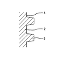
螺旋溝(4)と円筒状空洞部(31)との関係は、図5に示す通り、両者の間隙(d)は、ごく狭いもので、この間隙(d)に流れ込んだ液体原料(L)がその表面張力により、両者間に付着・保持されて流下して行かないような隙間が選ばれる。 As shown in FIG. 5, the relationship between the spiral groove (4) and the cylindrical cavity (31) is that the gap (d) between them is very narrow, and the liquid raw material (L) that has flowed into this gap (d) However, due to the surface tension, a gap is selected such that it adheres and is held between the two and does not flow down.
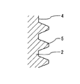
螺旋溝(4)を形成する螺旋条(5)は1本でもよいし複数本(多条)としてもよく、やはりこの場合も液体原料(L)の性質により最適のものが選択される。螺旋条(5)の形状は特段限定されるものではないが、例えば、断面が矩形状のもの(図7)、低い台形(図8)、三角形に近い台形(図9)或いは半円形(図10)など様々なものが考えられる。ただ、断面が矩形状のものに比べて、低い台形、三角形に近い台形或いは半円形のものは螺旋溝(4)に流入した液体原料(L)が間隙(d)に流れ込みやすく、後述するように蒸発速度が加速される。 The spiral groove (5) forming the spiral groove (4) may be one or plural (multiple), and in this case as well, the optimum one is selected depending on the properties of the liquid raw material (L). The shape of the spiral strip (5) is not particularly limited. For example, the spiral strip (5) has a rectangular cross section (FIG. 7), a low trapezoid (FIG. 8), a trapezoid close to a triangle (FIG. 9), or a semicircular shape (FIG. 10) and so on. However, the trapezoidal, nearly trapezoidal, or semicircular shape of the trapezoidal shape that is lower in cross section than the rectangular shape, the liquid raw material (L) that has flowed into the spiral groove (4) can easily flow into the gap (d), as described later. The evaporation rate is accelerated.
次に、本発明の作用について説明する。液体原料(L)を成膜装置の反応室へ供給する場合、開閉バルブ(12)は開状態に保持され、液体原料(L)は液体原料流量制御バルブ(11)に供給されるようになっている。液体原料(L)は液体用マスフローメータ(図示せず)に送られ、設定された質量流量の液体原料(L)を流量制御バルブ(11)に接続された流量制御弁室(15)に送り出す。開閉バルブ(12)は前述のように開状態であるから、液体原料(L)は流量制御弁室(15)の液体原料供給出口(10)が形成されている弁座(8)に至る。液体原料流量制御バルブ(11)には液体用マスフローメータから質量流量制御信号が送られてきており、前記制御信号に合わせて弁開度が調節され、液体原料流量制御バルブ(11)を所定の質量流量だけの液体原料(L)が気化部(1B)に供給される。 Next, the operation of the present invention will be described. When supplying the liquid source (L) to the reaction chamber of the film forming apparatus, the open / close valve (12) is kept open, and the liquid source (L) is supplied to the liquid source flow control valve (11). ing. The liquid material (L) is sent to a liquid mass flow meter (not shown), and the liquid material (L) having a set mass flow rate is sent to the flow control valve chamber (15) connected to the flow control valve (11). . Since the on-off valve (12) is in the open state as described above, the liquid material (L) reaches the valve seat (8) in which the liquid material supply outlet (10) of the flow control valve chamber (15) is formed. A mass flow control signal is sent from the liquid mass flow meter to the liquid raw material flow control valve (11), the valve opening is adjusted in accordance with the control signal, and the liquid raw material flow control valve (11) is set to a predetermined value. The liquid raw material (L) having only the mass flow rate is supplied to the vaporizing section (1B).
液体原料流量制御バルブ(11)の流量制御弁室(15)に開口した液体原料供給出口(10)から流出した液体原料(L)は液体原料供給導管(9)を通って気化部(1B)に送られ、通流空間(V)の頂部に開口している液体原料流入孔(7)から通流空間(V)内に滴下する。通流空間(V)内に流入した液体原料(L)はそのまま円錐状天井面(30)、或いは円錐状上端部(40)を伝って流下し、最終的にブロック本体(41)の外周に形成された螺旋溝(4)内に流入していく。 The liquid raw material (L) flowing out from the liquid raw material supply outlet (10) opened to the flow control valve chamber (15) of the liquid raw material flow control valve (11) passes through the liquid raw material supply conduit (9) and is vaporized (1B). And is dropped into the flow space (V) from the liquid raw material inflow hole (7) opened at the top of the flow space (V). The liquid raw material (L) flowing into the flow space (V) flows down the conical ceiling surface (30) or the conical upper end (40) as it is, and finally reaches the outer periphery of the block body (41). It flows into the formed spiral groove (4).
前記ブロック本体(41)及び気化部本体(1)は加熱ヒータ(H1)(H2)にて加熱されているので、それぞれの外・内面に付着した液膜は直ちに昇温し、液体原料(L)の一部は気化する。液体原料(L)の流入量が少ない場合には、螺旋溝(4)の入口から少し入った近傍部分ですべての液体原料(L)が加熱されて蒸発する。逆に、液体原料(L)の流入量が多い場合には、螺旋溝(4)の終端近くまで入り込み、その間ですべての液体原料(L)が加熱されて蒸発する。また、螺旋溝(4)に流入した液体原料(L)は図4に示すように、螺旋溝(4)に沿って流下するものと、螺旋条(5)の外周面と気化室(3)の内周面との僅かな間隙(d)に入り込むものがあるが、前者は液面から蒸発しながら下方へ流下にするのに対して後者の間隙(d)に入った液体原料(L)は、図6に示すように螺旋条(5)と気化部本体(1)からの熱を受けて迅速に蒸発する。これにより、キャリアガス(K)を用いることなく(或いは、後述するようにごく僅かのキャリアガの供給だけで)、液体原料(L)を迅速に気化することができる。 Since the block main body (41) and the vaporizing section main body (1) are heated by the heaters (H1) and (H2), the liquid films adhering to the outer and inner surfaces immediately rise in temperature, and the liquid raw material (L Part of) vaporizes. When the inflow amount of the liquid raw material (L) is small, all the liquid raw material (L) is heated and evaporated in the vicinity near the entrance of the spiral groove (4). On the contrary, when the inflow amount of the liquid raw material (L) is large, the liquid raw material (L) enters near the end of the spiral groove (4), and all the liquid raw material (L) is heated and evaporated in the meantime. Further, as shown in FIG. 4, the liquid raw material (L) flowing into the spiral groove (4) flows down along the spiral groove (4), the outer peripheral surface of the spiral strip (5), and the vaporization chamber (3). Although there is a thing that enters a slight gap (d) with the inner peripheral surface of the liquid, the former flows down while evaporating from the liquid surface, whereas the liquid raw material (L) entered the latter gap (d) As shown in FIG. 6, it rapidly evaporates upon receiving heat from the spiral strip (5) and the vaporizing section main body (1). Thereby, the liquid raw material (L) can be quickly vaporized without using the carrier gas (K) (or by supplying a very small amount of carrier gas as will be described later).
従って、螺旋溝(4)の断面形状は液体原料(L)が間隙(d)に流れ込みやすくなるように、台形、半円形或いは三角形のほうが好ましい。また、螺旋溝(4)の幅(l)や深さ(h)は小さいほど液体原料(L)の熱の伝達が効率的となるが、過少になると螺旋溝(4)の液体原料(L)の流入量が減少して却って気化率が悪くなるし、蒸発した原料ガス(G)の排出も悪くなる。 Therefore, the cross-sectional shape of the spiral groove (4) is preferably trapezoidal, semicircular or triangular so that the liquid raw material (L) can easily flow into the gap (d). Also, the smaller the width (l) and depth (h) of the spiral groove (4), the more efficient the heat transfer of the liquid raw material (L), but if the amount is too small, the liquid raw material (L ) Decreases, the vaporization rate worsens, and the evaporation of the evaporated source gas (G) also worsens.
このようにして蒸発した原料ガス(G)は螺旋溝(4)に沿って流れ、気化部(1B)の原料ガス出口(18)に向かって流れるほか、前記間隙(d)内に液体原料(L)が流れ込んでいない場合には、この間隙(d)を通って原料ガス出口(6)に向かって流れる。液体原料(L)の供給が完了すると、開閉バルブ(12)が作動して流量制御弁室(15)の液体原料供給出口(10)を閉じ、気化部(1B)への液体原料(L)の供給が停止される。 The source gas (G) evaporated in this way flows along the spiral groove (4), flows toward the source gas outlet (18) of the vaporization section (1B), and in the gap (d), the liquid source ( When L) does not flow, it flows through this gap (d) toward the raw material gas outlet (6). When the supply of the liquid raw material (L) is completed, the on-off valve (12) is operated to close the liquid raw material supply outlet (10) of the flow control valve chamber (15), and the liquid raw material (L) to the vaporization section (1B) Is stopped.
次に第2実施例について説明する。基本形である第1実施例と異なる部分を重点的に説明し、一致する部分については第1実施例の説明を援用する。第2実施例は図2に示すようにパージ部(1C)が液体原料供給部(1A)に含まれている場合である。パージ部(1C)は2方向開閉弁で構成されており、液体原料流量制御バルブ(11)に併設されていて、そのパージガス出口(50)が液体原料供給導管(9)の根本、即ち流量制御弁室(15)の直下に接続されている。パージ部(1C)のパージガス入口(51)はパージ部ガス供給導管(52)に接続されている。そして、液体原料(L)の供給が終了し、開閉バルブ(12)が作動して液体原料供給導管(9)の液体原料供給出口(10)を閉じるとパージ部(1C)が作動して開となり、パージガス(P)を液体原料供給導管(9)に送り込み、液体原料供給導管(9)内に残留している液体原料(L)を気化部(1B)に押し込む。これにより液体質量流量計により正確に計測されて供給された液体原料(L)はすべて気化器(1B)に送り込まれ、ここで気化されて次の成膜装置に供給されることになる。 Next, a second embodiment will be described. Parts different from the basic example of the first embodiment will be described with emphasis, and the description of the first embodiment will be used for the corresponding parts. In the second embodiment, as shown in FIG. 2, the purge unit (1C) is included in the liquid source supply unit (1A). The purge section (1C) is composed of a two-way opening / closing valve, and is provided along with the liquid material flow control valve (11), and its purge gas outlet (50) is the root of the liquid material supply conduit (9), that is, the flow control. Connected directly under the valve chamber (15). The purge gas inlet (51) of the purge unit (1C) is connected to the purge unit gas supply conduit (52). When the supply of the liquid raw material (L) is completed and the on-off valve (12) is operated to close the liquid raw material supply outlet (10) of the liquid raw material supply conduit (9), the purge unit (1C) is operated and opened. The purge gas (P) is sent to the liquid source supply conduit (9), and the liquid source (L) remaining in the liquid source supply conduit (9) is pushed into the vaporization section (1B). As a result, all the liquid raw material (L) accurately measured and supplied by the liquid mass flowmeter is sent to the vaporizer (1B), where it is vaporized and supplied to the next film forming apparatus.
前述の第1、2実施例はキャリアガス(K)を供給せず、液体原料(L)が気化した原料ガス(G)のみを供給する場合を説明したが、以下に述べる第3実施例は、ごく少量のキャリアガス(K)を供給する場合である。この場合は図3の破線で示すように気化部本体(1)の円錐状天井面(30)にキャリアガス供給用通孔(60)を形成し、このキャリアガス供給用通孔(60)にキャリアガス(K)の質量流量を制御する質量流量計を介してごく少量の所定量のキャリアガス(K)を通流空間(V)に供給する。このキャリアガス(K)は気化部(1B)内で気化した原料ガス(G)と共に次の成膜装置に供給される。供給されるキャリアガス(K)はごく僅かであるから、成膜装置内の内圧を大きく高めることがない。 In the first and second embodiments described above, the carrier gas (K) is not supplied, and only the source gas (G) in which the liquid source (L) is vaporized is described. However, the third embodiment described below is In this case, a very small amount of carrier gas (K) is supplied. In this case, as shown by the broken line in FIG. 3, a carrier gas supply through hole (60) is formed in the conical ceiling surface (30) of the vaporizer body (1), and the carrier gas supply through hole (60) is formed. A very small amount of a predetermined amount of carrier gas (K) is supplied to the flow space (V) via a mass flow meter that controls the mass flow rate of the carrier gas (K). This carrier gas (K) is supplied to the next film forming apparatus together with the source gas (G) vaporized in the vaporization section (1B). Since the supplied carrier gas (K) is very small, the internal pressure in the film forming apparatus is not greatly increased.
本発明は成膜装置の反応室の圧力低下という要求にこたえることができるもので、更なる半導体薄膜の膜特性の向上に大いに貢献することができるものである。 The present invention can meet the demand for lowering the pressure in the reaction chamber of the film forming apparatus, and can greatly contribute to further improving the film characteristics of the semiconductor thin film.
(A)…気化装置
(L)…液体原料
(1A)…液体原料供給部
(1B)…気化部
(1C)…パージ部
(G)…原料ガス
(d)…間隙
(1)…気化部本体
(2)…気化ブロック
(3)…気化室
(4)…螺旋溝
(5)…螺旋条
(A) ... Vaporizer
(L) ... Liquid raw material
(1A) ... Liquid material supply unit
(1B)… Vaporizer
(1C)… Purge section
(G)… Raw material gas
(d) ... Gap
(1) ... Vaporizer body
(2)… Vaporization block
(3)… Vaporization room
(4) ... Spiral groove
(5) ... Spiral strip
Claims (3)
気化部内に気化ブロックが収納され、前記気化ブロックとの間に間隙が設けられている気化室が形成されており、
気化室の内周面或いは気化ブロックの外周面の少なくともいずれか一方に、気化室に入り込んだ液体原料の流下用の螺旋溝が形成されていることを特徴とする気化装置の気化構造。 In the vaporization unit of the vaporizer that heats and vaporizes the liquid raw material supplied from the liquid raw material supply unit,
A vaporization block is housed in the vaporization section, and a vaporization chamber is formed in which a gap is provided between the vaporization block,
A vaporization structure of a vaporization device, wherein a spiral groove for flowing the liquid material that has entered the vaporization chamber is formed in at least one of the inner peripheral surface of the vaporization chamber and the outer peripheral surface of the vaporization block.
気化部内に気化ブロックが収納され、前記気化ブロックとの間に間隙が設けられている気化室が形成されており、
気化室の内周面或いは気化ブロックの外周面の少なくともいずれか一方に、気化室に入り込んだ液体原料の流下用の螺旋溝が形成されていることを特徴とする気化装置。 In a vaporization apparatus configured with a liquid raw material supply unit that supplies a liquid raw material to a vaporization unit, and a vaporization unit that heats and vaporizes the supplied liquid raw material,
A vaporization block is housed in the vaporization section, and a vaporization chamber is formed in which a gap is provided between the vaporization block,
A vaporizer characterized in that a spiral groove for flowing down the liquid raw material that has entered the vaporization chamber is formed on at least one of the inner peripheral surface of the vaporization chamber and the outer peripheral surface of the vaporization block.
The vaporizer according to claim 2, wherein the liquid source supply unit is provided with a purge unit for pushing out the liquid source remaining in the liquid source supply unit to the vaporization unit.
Priority Applications (1)
| Application Number | Priority Date | Filing Date | Title |
|---|---|---|---|
| JP2005012830A JP2006202965A (en) | 2005-01-20 | 2005-01-20 | Vaporizing apparatus and vaporizing structure |
Applications Claiming Priority (1)
| Application Number | Priority Date | Filing Date | Title |
|---|---|---|---|
| JP2005012830A JP2006202965A (en) | 2005-01-20 | 2005-01-20 | Vaporizing apparatus and vaporizing structure |
Publications (1)
| Publication Number | Publication Date |
|---|---|
| JP2006202965A true JP2006202965A (en) | 2006-08-03 |
Family
ID=36960684
Family Applications (1)
| Application Number | Title | Priority Date | Filing Date |
|---|---|---|---|
| JP2005012830A Pending JP2006202965A (en) | 2005-01-20 | 2005-01-20 | Vaporizing apparatus and vaporizing structure |
Country Status (1)
| Country | Link |
|---|---|
| JP (1) | JP2006202965A (en) |
Cited By (4)
| Publication number | Priority date | Publication date | Assignee | Title |
|---|---|---|---|---|
| WO2009122966A1 (en) * | 2008-03-31 | 2009-10-08 | 東京エレクトロン株式会社 | Liquid raw material vaporizer and film forming apparatus using the same |
| JP2016143798A (en) * | 2015-02-03 | 2016-08-08 | 株式会社リンテック | Vaporizer |
| JP2017147447A (en) * | 2016-02-18 | 2017-08-24 | 三星電子株式会社Samsung Electronics Co.,Ltd. | Vaporizer and thin film deposition device including the same |
| WO2022075111A1 (en) * | 2020-10-07 | 2022-04-14 | 東京エレクトロン株式会社 | Vaporization device, gas supply device and control method for gas supply device |
Citations (3)
| Publication number | Priority date | Publication date | Assignee | Title |
|---|---|---|---|---|
| JPH02145768A (en) * | 1988-11-28 | 1990-06-05 | Koujiyundo Kagaku Kenkyusho:Kk | Raw liquid vaporizer |
| JPH09235675A (en) * | 1995-12-28 | 1997-09-09 | Ebara Corp | Liquid raw material evaporating device |
| JP2005175249A (en) * | 2003-12-12 | 2005-06-30 | Japan Pionics Co Ltd | Apparatus and method for vaporizing liquid material |
-
2005
- 2005-01-20 JP JP2005012830A patent/JP2006202965A/en active Pending
Patent Citations (3)
| Publication number | Priority date | Publication date | Assignee | Title |
|---|---|---|---|---|
| JPH02145768A (en) * | 1988-11-28 | 1990-06-05 | Koujiyundo Kagaku Kenkyusho:Kk | Raw liquid vaporizer |
| JPH09235675A (en) * | 1995-12-28 | 1997-09-09 | Ebara Corp | Liquid raw material evaporating device |
| JP2005175249A (en) * | 2003-12-12 | 2005-06-30 | Japan Pionics Co Ltd | Apparatus and method for vaporizing liquid material |
Cited By (8)
| Publication number | Priority date | Publication date | Assignee | Title |
|---|---|---|---|---|
| WO2009122966A1 (en) * | 2008-03-31 | 2009-10-08 | 東京エレクトロン株式会社 | Liquid raw material vaporizer and film forming apparatus using the same |
| JP2009246168A (en) * | 2008-03-31 | 2009-10-22 | Tokyo Electron Ltd | Liquid raw material vaporizer and film forming device using the same |
| KR101177216B1 (en) | 2008-03-31 | 2012-08-24 | 도쿄엘렉트론가부시키가이샤 | Liquid raw material vaporizer and film forming apparatus using the same |
| JP2016143798A (en) * | 2015-02-03 | 2016-08-08 | 株式会社リンテック | Vaporizer |
| JP2017147447A (en) * | 2016-02-18 | 2017-08-24 | 三星電子株式会社Samsung Electronics Co.,Ltd. | Vaporizer and thin film deposition device including the same |
| KR20170097427A (en) * | 2016-02-18 | 2017-08-28 | 삼성전자주식회사 | Vaporizer and thin film deposition apparatus having the same |
| KR102483924B1 (en) * | 2016-02-18 | 2023-01-02 | 삼성전자주식회사 | Vaporizer and thin film deposition apparatus having the same |
| WO2022075111A1 (en) * | 2020-10-07 | 2022-04-14 | 東京エレクトロン株式会社 | Vaporization device, gas supply device and control method for gas supply device |
Similar Documents
| Publication | Publication Date | Title |
|---|---|---|
| JP4601535B2 (en) | A vaporizer capable of vaporizing liquid raw materials at low temperatures | |
| US7294208B2 (en) | Apparatus for providing gas to a processing chamber | |
| JP5350824B2 (en) | Liquid material vaporization supply system | |
| CN105386012A (en) | Methods and apparatuses for stable deposition rate control in low temperature | |
| WO2006101697A3 (en) | Vaporizer and method of vaporizing a liquid for thin film delivery | |
| CN102917744A (en) | Liquid tank for aerosol aspirator | |
| WO2007114474A1 (en) | Liquid material vaporizer | |
| JP2006202965A (en) | Vaporizing apparatus and vaporizing structure | |
| US11448423B2 (en) | Hot liquid generation module for liquid treatment apparatus | |
| TWI672756B (en) | Fluid heater, heating block and vaporization system | |
| CN106661719A (en) | Device and method for generating vapor for a CVD- or PVD device | |
| JPH0795527B2 (en) | Vaporizer for liquid raw materials | |
| JP2007046084A (en) | Vaporizer, and liquid vaporizing-feeding device using the same | |
| JPH10337464A (en) | Gasification device of liquid material | |
| JP5914702B2 (en) | Dual venturi for water heater | |
| TW202108928A (en) | Vaporizer | |
| KR102238368B1 (en) | Vaporizing apparatus using in semiconductor equipment | |
| TWI383065B (en) | Apparatus and method for supplying source gas | |
| KR20150055881A (en) | Apparatus for supplying material source | |
| JP2008212884A (en) | Liquid concentrator | |
| KR100322411B1 (en) | Apparatus for vaporizing a liquid source | |
| TWI661487B (en) | Carburetor and semiconductor processing system using the same | |
| US1069374A (en) | Method of producing hot water by means of electricity and apparatus therefor. | |
| KR100455224B1 (en) | Vaporizer | |
| KR101415664B1 (en) | Vaporizer and Depositing Apparatus including Vaporizer |
Legal Events
| Date | Code | Title | Description |
|---|---|---|---|
| A621 | Written request for application examination |
Effective date: 20070117 Free format text: JAPANESE INTERMEDIATE CODE: A621 |
|
| A977 | Report on retrieval |
Free format text: JAPANESE INTERMEDIATE CODE: A971007 Effective date: 20090304 |
|
| A131 | Notification of reasons for refusal |
Free format text: JAPANESE INTERMEDIATE CODE: A131 Effective date: 20090310 |
|
| A521 | Written amendment |
Effective date: 20090511 Free format text: JAPANESE INTERMEDIATE CODE: A523 |
|
| A02 | Decision of refusal |
Free format text: JAPANESE INTERMEDIATE CODE: A02 Effective date: 20100608 |