JP5914702B2 - Dual venturi for water heater - Google Patents
Dual venturi for water heater Download PDFInfo
- Publication number
- JP5914702B2 JP5914702B2 JP2014558663A JP2014558663A JP5914702B2 JP 5914702 B2 JP5914702 B2 JP 5914702B2 JP 2014558663 A JP2014558663 A JP 2014558663A JP 2014558663 A JP2014558663 A JP 2014558663A JP 5914702 B2 JP5914702 B2 JP 5914702B2
- Authority
- JP
- Japan
- Prior art keywords
- damper
- secondary gas
- tube
- passage
- dual venturi
- Prior art date
- Legal status (The legal status is an assumption and is not a legal conclusion. Google has not performed a legal analysis and makes no representation as to the accuracy of the status listed.)
- Active
Links
- 230000009977 dual effect Effects 0.000 title claims description 29
- XLYOFNOQVPJJNP-UHFFFAOYSA-N water Substances O XLYOFNOQVPJJNP-UHFFFAOYSA-N 0.000 title description 23
- 238000005192 partition Methods 0.000 claims description 10
- 230000001360 synchronised effect Effects 0.000 claims description 6
- 239000000523 sample Substances 0.000 description 10
- 238000010438 heat treatment Methods 0.000 description 6
- 238000004519 manufacturing process Methods 0.000 description 5
- 238000003860 storage Methods 0.000 description 4
- 239000013505 freshwater Substances 0.000 description 3
- 238000005516 engineering process Methods 0.000 description 2
- 238000000034 method Methods 0.000 description 2
- 238000012986 modification Methods 0.000 description 2
- 230000004048 modification Effects 0.000 description 2
- 238000004378 air conditioning Methods 0.000 description 1
- 238000002485 combustion reaction Methods 0.000 description 1
- 238000004891 communication Methods 0.000 description 1
- 238000010586 diagram Methods 0.000 description 1
- 238000009826 distribution Methods 0.000 description 1
- 238000005315 distribution function Methods 0.000 description 1
- 230000000694 effects Effects 0.000 description 1
Images


Classifications
-
- F—MECHANICAL ENGINEERING; LIGHTING; HEATING; WEAPONS; BLASTING
- F23—COMBUSTION APPARATUS; COMBUSTION PROCESSES
- F23D—BURNERS
- F23D14/00—Burners for combustion of a gas, e.g. of a gas stored under pressure as a liquid
- F23D14/02—Premix gas burners, i.e. in which gaseous fuel is mixed with combustion air upstream of the combustion zone
- F23D14/04—Premix gas burners, i.e. in which gaseous fuel is mixed with combustion air upstream of the combustion zone induction type, e.g. Bunsen burner
-
- F—MECHANICAL ENGINEERING; LIGHTING; HEATING; WEAPONS; BLASTING
- F23—COMBUSTION APPARATUS; COMBUSTION PROCESSES
- F23N—REGULATING OR CONTROLLING COMBUSTION
- F23N1/00—Regulating fuel supply
- F23N1/02—Regulating fuel supply conjointly with air supply
-
- F—MECHANICAL ENGINEERING; LIGHTING; HEATING; WEAPONS; BLASTING
- F23—COMBUSTION APPARATUS; COMBUSTION PROCESSES
- F23D—BURNERS
- F23D14/00—Burners for combustion of a gas, e.g. of a gas stored under pressure as a liquid
- F23D14/46—Details, e.g. noise reduction means
- F23D14/60—Devices for simultaneous control of gas and combustion air
-
- F—MECHANICAL ENGINEERING; LIGHTING; HEATING; WEAPONS; BLASTING
- F23—COMBUSTION APPARATUS; COMBUSTION PROCESSES
- F23D—BURNERS
- F23D14/00—Burners for combustion of a gas, e.g. of a gas stored under pressure as a liquid
- F23D14/46—Details, e.g. noise reduction means
- F23D14/62—Mixing devices; Mixing tubes
-
- F—MECHANICAL ENGINEERING; LIGHTING; HEATING; WEAPONS; BLASTING
- F23—COMBUSTION APPARATUS; COMBUSTION PROCESSES
- F23L—SUPPLYING AIR OR NON-COMBUSTIBLE LIQUIDS OR GASES TO COMBUSTION APPARATUS IN GENERAL ; VALVES OR DAMPERS SPECIALLY ADAPTED FOR CONTROLLING AIR SUPPLY OR DRAUGHT IN COMBUSTION APPARATUS; INDUCING DRAUGHT IN COMBUSTION APPARATUS; TOPS FOR CHIMNEYS OR VENTILATING SHAFTS; TERMINALS FOR FLUES
- F23L3/00—Arrangements of valves or dampers before the fire
-
- F—MECHANICAL ENGINEERING; LIGHTING; HEATING; WEAPONS; BLASTING
- F23—COMBUSTION APPARATUS; COMBUSTION PROCESSES
- F23N—REGULATING OR CONTROLLING COMBUSTION
- F23N3/00—Regulating air supply or draught
- F23N3/06—Regulating air supply or draught by conjoint operation of two or more valves or dampers
-
- F—MECHANICAL ENGINEERING; LIGHTING; HEATING; WEAPONS; BLASTING
- F24—HEATING; RANGES; VENTILATING
- F24H—FLUID HEATERS, e.g. WATER OR AIR HEATERS, HAVING HEAT-GENERATING MEANS, e.g. HEAT PUMPS, IN GENERAL
- F24H9/00—Details
- F24H9/20—Arrangement or mounting of control or safety devices
- F24H9/2007—Arrangement or mounting of control or safety devices for water heaters
- F24H9/2035—Arrangement or mounting of control or safety devices for water heaters using fluid fuel
-
- F—MECHANICAL ENGINEERING; LIGHTING; HEATING; WEAPONS; BLASTING
- F23—COMBUSTION APPARATUS; COMBUSTION PROCESSES
- F23D—BURNERS
- F23D2203/00—Gaseous fuel burners
- F23D2203/007—Mixing tubes, air supply regulation
Description
本発明は、給湯器用空気及びガスの混合バルブに関し、より詳しくは給湯器に備えられるバーナーにガス及び空気を供給する量を制御して、より効率よく熱量を制御するための給湯器用空気及びガスの混合バルブに関する。 The present invention relates to a water heater air and gas mixing valve, and more particularly, to control the amount of gas and air supplied to a burner provided in the water heater to control the amount of heat more efficiently. This relates to the mixing valve.
一般にガス給湯器システムは暖房用ではなく、洗面若しくはシャワーなどを浴びるとき、低温の真水を温めて温水にして供給し、生活の便宜を提供する暖房機器であって、瞬間式ガス給湯器システムと貯蔵式ガス給湯器システムの二つの方式がある。 In general, a gas water heater system is not for heating, but when taking a wash surface or a shower, etc., it is a heating device that provides low temperature fresh water and supplies it as hot water, and provides convenience of living. There are two types of storage gas water heater systems.
上記方式のうち、瞬間式ガス給湯器システムは、瞬間式熱交換器を用いて真水を瞬間的に所望の量だけ加熱して温水を出湯する構成を有し、貯蔵式ガス給湯器システムは、貯蔵タンクの中に温水を溜めて一定の温度に保持且つ供給することができる構成を有する。 Among the above methods, the instantaneous gas water heater system has a configuration that instantaneously heats fresh water by a desired amount using an instantaneous heat exchanger to discharge hot water, and the storage gas water heater system is It has a configuration in which hot water can be stored in a storage tank and maintained and supplied at a constant temperature.
上述の二つの方式のガス給湯システムには、低温の真水を加熱するための加熱手段が備えられ、前記加熱手段は、ガス調節器を介して供給されるガスと、送風機を介して供給される空気が混合バルブによって混合され、その混合ガスがバーナーに供給される。 The above-described two types of gas hot-water supply systems are provided with heating means for heating low-temperature fresh water, and the heating means is supplied via a gas regulator and a blower. Air is mixed by the mixing valve, and the mixed gas is supplied to the burner.
上記特許文献1は、瞬間式ガス給湯器と貯蔵式ガス給湯器を複合的に製作してコンパクトでありながらも、冷水と温水の温度差を低減して安定的にガス給湯器が用いられるようにする複合形ガス給湯器システムに関するものである。 Although the above-mentioned Patent Document 1 is compact by combining an instantaneous type gas water heater and a storage type gas water heater, the gas water heater can be used stably by reducing the temperature difference between cold water and hot water. The present invention relates to a combined gas water heater system.
上記特許文献1において、バーナー28に空気及びガスを供給する方法は、図6に示すようにガスの量を調節するガス調節器22を介して供給されるガスが、ノズル26を通じて上部へ熱を放出する構造である。このとき、前記バーナー28へ送風機24が空気を供給するようになって、ガスの燃焼率を高めるものである。
In the above Patent Document 1, the method of supplying air and gas to the
しかしながら、上述したガス給湯器システムは、単に空気とガスが混合されてバーナーに供給される構造であって、ユーザーが必要とする温水を加熱するためのバーナーの熱量の多寡に応じてガス及び空気の供給量を制御する機能がないことから、熱量によって温水器を製作しなければならないので、製作コストが増加するという問題点がある。 However, the above-described gas water heater system has a structure in which air and gas are simply mixed and supplied to the burner, and the gas and air according to the amount of heat of the burner for heating hot water required by the user. Since there is no function to control the supply amount of water, the water heater must be manufactured by the amount of heat, which increases the manufacturing cost.
本発明は、上記課題を解決するためのものであって、複雑な構造をより簡素化して装置をコンパクト化しながらも、作動の信頼性が高くて製造が容易であり、かつ製造コストを低減できる給湯器用デュアルベンチュリを提供することを目的とする。
本発明のもう一つの目的は、1次側と2次側の空気及びガスの比率を独立的に制御できる給湯器用デュアルベンチュリを提供することである。
The present invention is for solving the above-described problems, and while simplifying the complicated structure and making the apparatus compact, the operation is highly reliable and easy to manufacture, and the manufacturing cost can be reduced. An object is to provide a dual venturi for a water heater.
Another object of the present invention is to provide a dual venturi for a water heater that can independently control the ratio of air and gas between the primary side and the secondary side.
上記目的を具現するための本発明の第1の構成の特徴は、筒状のダクトであって内部に隔壁を挟んで分離された1次通路及び2次通路を有し、前記1通路の側壁には1次ガス流入部が形成された管形状部と、前記管形状部の前記2次通路内に位置し、上部表面を有するボディ部であって、前記上部表面が、前記管形状部の横断面方向の水平面の方向と、前記水平面に対して直交する垂直面の方向との間で回転しながら2次空気の流れを開閉するボディ部と、ダンパー部側の2次ガス出口を有するダンパー部と、前記ダンパー部の側面に回転軸を有して連結され、前記水平面と前記垂直面に前記ダンパー部を回転駆動する駆動部と、前記ダンパー部の回転位置によって前記ダンパー部側の2次ガス出口と選択的に連通するガス流入部側の2次ガス出口を有し、前記ダンパー部を介して2次ガスを管形状部の前記2次通路に導入し、前記駆動部の回転軸とともにダンパー部の回転軸を形成する2次ガス流入部と、を備える。 A feature of the first configuration of the present invention for realizing the above object is a cylindrical duct having a primary passage and a secondary passage separated inside with a partition wall therebetween, and a side wall of the first passage Is a body part having an upper surface located in the secondary passage of the tube-shaped part, the tube-shaped part in which a primary gas inflow part is formed, and the upper surface is formed of the tube-shaped part. A body portion that opens and closes a flow of secondary air while rotating between a horizontal plane direction in a cross-sectional direction and a vertical plane direction orthogonal to the horizontal plane, and a damper having a secondary gas outlet on the damper portion side , A drive unit that is connected to a side surface of the damper unit with a rotation shaft, and that rotates the damper unit on the horizontal and vertical surfaces, and a secondary side on the damper unit side according to a rotational position of the damper unit. Secondary gas on the gas inlet side that is selectively in communication with the gas outlet A secondary gas inflow part that has an outlet, introduces secondary gas into the secondary passage of the tube-shaped part through the damper part, and forms the rotational axis of the damper part together with the rotational axis of the drive part; Prepare.
好ましくは、前記駆動部は同期モータを含み、前記駆動部の前記回転軸は前記同期モータの回転軸であることを特徴とする。 Preferably, the driving unit includes a synchronous motor, and the rotating shaft of the driving unit is a rotating shaft of the synchronous motor.
好ましくは、前記2次ガス流入部側出口は、前記ダンパー部の前記ボディ部の前記上部表面が前記垂直面の方向に位置するとき、前記ダンパー部側の2次ガス出口と連通する。 Preferably, the secondary gas inflow portion side outlet communicates with the secondary gas outlet on the damper portion side when the upper surface of the body portion of the damper portion is positioned in the direction of the vertical plane.
好ましくは、前記駆動部は、前記ダンパー部の前記垂直面の方向位置と前記水平面の方向位置を表示するリミットスイッチを含む。 Preferably, the drive unit includes a limit switch that displays a directional position of the vertical surface of the damper unit and a directional position of the horizontal plane.
好ましくは、前記管形状部は、中間の径幅が中間から上端と下端へ進むにつれて径幅が大きくなる。 Preferably, the tube-shaped portion increases in diameter as the intermediate diameter width proceeds from the middle to the upper end and the lower end.
好ましくは、前記ダンパー部側の2次ガス出口は、前記ボディ部の前記上部表面が前記水平面の方向に位置するとき、前記管形状部の上側方向を向くように外側表面に形成される。 Preferably, the secondary gas outlet on the damper portion side is formed on the outer surface so that the upper surface of the body portion faces the upper side of the tube-shaped portion when the upper surface of the body portion is positioned in the horizontal plane direction.
好ましくは、前記ダンパー部側の2次ガス出口は、前記ボディ部の前記上部表面が前記水平面の方向に位置するとき、前記管形状部の上側方向及び下側方向の両方を向くように外側表面に形成される。 Preferably, the secondary gas outlet on the damper portion side has an outer surface so as to face both an upper side direction and a lower side direction of the tube-shaped portion when the upper surface of the body portion is positioned in the horizontal plane direction. Formed.
好ましくは、前記2次ガス流入部側の出口は1つだけ形成され、前記ダンパー部が前記垂直面の方向に位置するとき、前記ダンパー部側の2次ガス出口に連通する。 Preferably, only one outlet on the secondary gas inflow portion side is formed and communicates with the secondary gas outlet on the damper portion side when the damper portion is positioned in the direction of the vertical plane.
好ましくは、前記2次ガス流入部側の出口は2つ形成され、前記ダンパー部が前記垂直面の方向に位置するとき、前記ダンパー部側の2次ガス出口に連通する。 Preferably, two outlets on the secondary gas inflow portion side are formed, and communicate with the secondary gas outlet on the damper portion side when the damper portion is positioned in the direction of the vertical plane.
上述の構成特徴を通じて本発明は以下のような効果が得られる。 Through the above-described configuration features, the present invention provides the following effects.
第一に、管形状部の内部を隔壁で分けて1次通路と2次通路を形成し、1次通路には1次空気及び1次ガスだけが流れ、2次通路には2次空気及び2ガス気だけが流れるので、1次側の流れと2次側の流れの空気比を容易に調節できる。 First, the inside of the tube-shaped portion is divided by a partition to form a primary passage and a secondary passage, and only the primary air and the primary gas flow in the primary passage, and the secondary air and Since only two gas flows, the air ratio between the primary side flow and the secondary side flow can be easily adjusted.
第二に、2次ガス流入部の一方の開口を2次ガス出口にしてダンパー部の回転によって2次ガス出口を開閉するとともに、2次空気通路も開閉するので、その構造が簡素化される。 Secondly, since one opening of the secondary gas inflow portion is used as the secondary gas outlet, the secondary gas outlet is opened and closed by the rotation of the damper portion, and the secondary air passage is also opened and closed, thereby simplifying the structure. .
第三に、モータ回転軸と円筒状のガス流入部をダンパー部の回転軸として用いるので、別個の回転軸を設ける必要がなく、さらにダンパー部の回転によって停止した2次ガス流入部のガス出口が開閉されるので、その構造の簡素化に加えて作動の信頼性も高くなる。 Thirdly, since the motor rotation shaft and the cylindrical gas inflow portion are used as the rotation shaft of the damper portion, there is no need to provide a separate rotation shaft, and the gas outlet of the secondary gas inflow portion stopped by the rotation of the damper portion. Since this is opened and closed, the reliability of the operation is enhanced in addition to the simplification of the structure.
第四に、管形状部は、一般に広く用いられている空調設備を利用できることから、製造が容易であり、同期モータを用いて駆動部のモータの回転軸にダンパー部が直接的に連結する構造であるため、ワイヤやスプリングのような更なる構成要素を必要としないことから構造がよりコンパクト化して、全体容積を減らすことができる。 Fourth, since the tube-shaped part can use generally widely used air conditioning equipment, it is easy to manufacture, and a structure in which the damper part is directly connected to the rotating shaft of the motor of the driving part using a synchronous motor. Therefore, since no additional components such as wires and springs are required, the structure can be made more compact and the overall volume can be reduced.
第五に、上記の第一から第四の理由によって、構造の簡素化、及び製造コストの低減を図ることができる。 Fifth, for the above first to fourth reasons, the structure can be simplified and the manufacturing cost can be reduced.
以下、本発明の実施例について図面を参照してより詳細に説明する。 Hereinafter, embodiments of the present invention will be described in more detail with reference to the drawings.
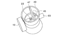
先ず、図1、図2a及び図2bを参照して、本発明の一実施例に係るデュアルベンチュリの全体構造を説明する。図1は、本発明の実施例に係るデュアルベンチュリの構造を説明する分解斜視図である。図2aは本発明に係る実施例であって、ダンパー部が閉じられた状態を示すデュアルベンチュリの縦断面図であり、図2bは、ダンパー部が開かれた状態を示すデュアルベンチュリの縦断面図をそれぞれ示す。 First, an overall structure of a dual venturi according to an embodiment of the present invention will be described with reference to FIGS. 1, 2a and 2b. FIG. 1 is an exploded perspective view illustrating the structure of a dual venturi according to an embodiment of the present invention. 2A is a longitudinal sectional view of a dual venturi according to an embodiment of the present invention, showing a state where the damper portion is closed, and FIG. 2B is a longitudinal sectional view of the dual venturi, showing a state where the damper portion is opened. Respectively.
本発明に係るデュアルベンチュリは、隔壁47を挟んで分離された1次通路43と、2次通路44(図2a、図2b参照)を有し、1次通路43の側壁の中間に1次ガス流入部45を有する管形状部40と、管形状部40に位置して管形状部40の下段43から上段方向へ進む2次空気の通路となる2次通路を開閉するダンパー部20と、管形状部40の側面に位置して管形状部側の第2の孔42を介して挿入されたモータの回転軸15がダンパー部側の第1の孔23に結合されてダンパー部20を回転させる駆動部10と、そして管形状部40の第1の孔41を介して挿入され、次に1次通路42を横切って隔壁47を通じて2次通路44内でダンパー部側の第2の孔27(図3c参照)に連結され、ダンパー部20を介して2次ガスを供給する円筒状の2次ガス流入部60とから構成される。このように、管形状部40は隔壁47により分離された1次通路43が1次空気及び1次ガスだけを通過させ、2次通路44が2次空気及び2次ガスだけを通過させるので、1次混合気流と2次混合気流の空気‐ガスの比を効率よく調節できる。
The dual venturi according to the present invention has a
図1に示すように、本実施例の管形状部40は、中央部の径が上下両端部側の径よりも小径になっていて、その中央部の通路が狭く形成されている。この形状は、図2a及び図2bからより明らかになっている。しかしながら、管形状部40の形状は、上下が一様の円筒状にすることもでき、本発明においては、特にその形状を特定するものではない。
As shown in FIG. 1, the tube-
上記のダンパー部20は、全体が半円形状且つ水平方向の時は、管形状部40の2次通路44を遮断することができる程度の水平面積を有しているボディ部29と、このボディ部29の上部表面には2次ガスが出るスロット状の孔が4つ形成されたダンパー部側の2次ガス出口22を有しており、これと対称するボディ部29にもまた2次ガス出口を有してもよい。即ち、2次ガス出口22に対応する下部表面にも形成できる。また、スロット状孔は4つに図示されているが、その個数は必要に応じて適宜定めることもでき、その形状も変更できる。
The
図2a及び図2bに示すように、ダンパー部20側と接する2次ガス流入部60の末端部はダンパー部によって閉鎖された状態である。
As shown in FIGS. 2a and 2b, the end portion of the secondary
2次ガス流入部60は円筒状になっており、管形状部側の第1の孔41を介して挿入されて1次通路43と隔壁47を通じて2次通路44内でダンパー部側の第2の孔27(図8c参照)に結合される。この場合、2次ガス流入部60は回転しないが、ダンパー部20は回転できるので、2次ガス流入部60は、モータの回転軸15と相俟ってダンパー部20の回転のための固定軸としての機能も兼ねている。2次ガス流入部60のダンパー部側の一端は上述のように閉鎖された状態となり、2次ガス流入部60のダンパー部側付近の周りには、ダンパー部側の2次ガス出口22と一致する形状の2次ガス流入部側の2次ガス出口62が形成されている。2次ガス流入部側の2次ガス出口62も対称形状を有し管の両側へ出口を形成することもできるし、片側にだけ出口を形成することもできる。図2aはダンパー部20が閉鎖された状態、即ち、管形状部40の2次通路44の上下方向の通路が塞がり、ダンパー部20の第1の通路43だけが管形状部40の1次空気及び1次ガスを通過させる通路として用いられる状態を示す。言い換えれば、管形状部40の横断面方向、即ち、水平面にダンパー部20が置かれていて、1次ガス流入部45だけが管形状部40の第1通路へ開かれた状態であり(常時開かれた状態を保持する)、2次ガス流入部側の2次ガス出口62は閉鎖された状態を示す。
The secondary
図2bはダンパー部20が開放された状態、即ち、管形状部40の上下方向の通路が開かれて実質的に管形状部40の第1の通路43だけでなく、第2の通路44もほとんどが空気通路として用いられる状態であって、いわば2次空気が通じる状態を示す。この場合、ダンパー部20は、水平面に対して直交する垂直面に置かれ、1次ガス流入部45は言うまでもなく、2次ガス流入部側の2次ガス出口62もダンパー部側の2次ガス出口22と一緒に開かれた状態となる。その結果、1段階流通と2段階流通の両機能がともに行われることになる。
FIG. 2 b shows a state in which the
次に、図3aから図5bを参照して、本発明の一実施例に係るデュアルベンチュリの動作を説明しながら、上述の構成説明において十分に説明されていない構成部分は更に説明する。 Next, with reference to FIGS. 3 a to 5 b, the operation of the dual venturi according to one embodiment of the present invention will be described, and components not fully described in the above description of the configuration will be further described.
先ず、図3a、図3b及び図3cは、本発明の一実施例に係るダンパー部20が閉じられたデュアルベンチュリの状態を示す図であって、図3aは斜視図であり、図3bは平断面図である。そして図3cは2次ガス流入部とダンパー部の各2次ガス出口との位置関係を示す断面図である。
First, FIGS. 3a, 3b, and 3c are views showing a dual venturi state in which the
図3aの斜視図に示すように、ダンパー部20が閉鎖される場合、管形状部40とダンパー部20との位置関係は、管形状部40の2次通路44の上下方向の空気通路全体をダンパー部20が遮断した状態であり、1次通路43だけが実質的に管形状部40の空気通路(1次空気通路)となる。即ち、ダンパー部20が管形状部40の横断面方向の水平面に置かれ、このとき、図3bから確認されるように、1次ガス流入部45だけが管形状部40側に開かれて(常時開かれた状態)、管形状部40内に1次ガスが流れるようになり、2次ガス流入部側の2次ガス出口62は、図3cに示すように、ダンパー部側の第2の孔27の壁に塞がれて閉鎖される。即ち、閉鎖状態では、管形状部40の1次通路を通じて相対的に少量の1次空気と1次ガスが送られることになる。
As shown in the perspective view of FIG. 3 a, when the
図4a及び図4bは本発明に係る一実施例であり、ダンパー部が開かれたデュアルベンチュリの状態を示す図であって、図4aは平断面図であり、図4bはダンパー部の2次ガス流入部と各2次ガス出口との位置関係を示す断面図である。 4a and 4b are diagrams showing a dual venturi state in which a damper portion is opened according to an embodiment of the present invention, wherein FIG. 4a is a plan sectional view, and FIG. 4b is a secondary portion of the damper portion. It is sectional drawing which shows the positional relationship of a gas inflow part and each secondary gas exit.
図4aの断面図に示すように、ダンパー部20が開放される場合、管形状部40とダンパー部20との位置関係は、第2の通路44が開かれて管形状部40の上下方向の空気通路全体を実質的に開放する状態となる。即ち、管形状部40の2次通路44の横断面方向に対し垂直面に、言い換えれば、ダンパー部20が閉鎖状態に置かれた水平面方向に対して垂直方向に立てて置かれ、このとき、図4aに示すように、1次ガス流入部45を介して1次ガスが流れるのは言うまでもなく、2次ガス流入部側の2次ガス出口62の方も開かれて第2の通路44に2次ガスが流れ出る。
As shown in the sectional view of FIG. 4a, when the
図4bを参照すれば、ダンパー部側の第2の孔27の壁に形成されたダンパー部側の2次ガス出口22と2次ガス流入部の2次ガス出口62が一致して相互に連通していることが分かる。
Referring to FIG. 4b, the
本実施例における2次ガス流入部側の2次ガス出口62は、円周の片側だけに形成されてダンパー部20の一つの側面の表面(例えば、管形状部40の上下方向のうち、上方向側面)にだけ2次ガスが噴出されるが、例えば、円筒状の2次ガス流入部60の壁側の円周の反体側(即ち、180°の方向)にも2次ガス流入部側の2次ガス出口62を設けてダンパー部20の上下方向へ2次ガスが噴出されるようにしてもよい。
In the present embodiment, the
図5a及び図5bは、本発明における一実施例に係る駆動部のリミットスイッチにおいて、そのダンパー部と2次ガス流入部の2次ガス出口の位置関係を示す図であって、図5aは平面図であり、図5bは側面図をそれぞれ示す。 5a and 5b are views showing the positional relationship between the damper part and the secondary gas outlet of the secondary gas inflow part in the limit switch of the driving part according to one embodiment of the present invention. FIG. Figure 5b shows a side view respectively.
図5aのリミットスイッチ11において、符号211aと211bはダンパー部側の2次ガス出口位置点を示し、211cと211dは2次ガス流入部側の2次ガス出口位置点をそれぞれ示し、211gはダンパー部側の位置探針棒、211hは2次ガス流入部側の位置探針棒をそれぞれ示す。ダンパー部側の位置探針棒211gにダンパー部側の2次ガス出口位置点211a、211bのいずれかが位置し、同様に2次ガス流入部側の位置探針棒211hに2次ガス流入部側の2次ガス出口位置点211c、211dのいずれかが位置すれば、この場合は図3cのように2次空気と2次ガスが遮断された状態になる。即ち、ダンパー部20が水平方向位置にある状態を示す。
In the limit switch 11 of FIG. 5a,
そして、逆にダンパー部側の位置探針棒211gに2次ガス流入部側の2次ガス出口位置点211c、211dのいずれかが位置し、同様に2次ガス流入部側の位置探針棒211hにダンパー部側の2次ガス出口位置点211a、211bのいずれかが位置すれば、この場合は、図4aのように2次空気と2次ガスが開放されて管形状部40へ流れる状態になる。即ち、ダンパー部20が垂直方向位置にある状態を示す。
On the other hand, either the secondary gas inflow portion side secondary gas
図5bを参照すれば、駆動部10に含まれるモータ13には同期式モータを用い、モータ13の回転軸15がダンパー部側の第1の孔23に直接的に結合することができ、ACモータを使用する従来技術において必然的に備えられなければならないワイヤ、復帰スプリングなどの構成要素が省けることから、本発明に係るデュアルベンチュリの構造がこの点においても従来技術に比べてより構成上簡素化できる。
Referring to FIG. 5b, a synchronous motor is used as the
以上、本発明の好ましい実施例について説明してきたが、本発明はこれに限定されることなく、当分野の通常の技術者にとって種々の変更、改良可能なことは言うまでもない。例えば、リミットスイッチの組合せでは、ダンパー部側の探針棒と2次ガス流入部側の探針棒との各2次ガス出口の位置点がずれるときを2次ガス開放状態に設定したが、その逆にしても現実的に同じ結果を表示するように設定すれば差し支えない。また、1次ガス流入部の位置も、上記実施例においては管形状部の隔壁の位置もその用途に合わせて変更したり、1次通路と2次通路の流量速度によって変更したりすることもできる。即ち、明白に予想できる多様な変更及び変形例は、本発明の範囲に属することは明らかである。 The preferred embodiments of the present invention have been described above, but the present invention is not limited to these embodiments, and it goes without saying that various modifications and improvements can be made by those skilled in the art. For example, in the combination of limit switches, when the position point of each secondary gas outlet of the probe rod on the damper portion side and the probe rod on the secondary gas inflow portion side is set to the secondary gas release state, Even if the reverse is true, it may be set to display the same result practically. In addition, the position of the primary gas inflow portion and the position of the partition wall of the tube-shaped portion in the above embodiment may be changed according to the application, or may be changed depending on the flow rate of the primary passage and the secondary passage. it can. That is, it is apparent that various modifications and variations that can be clearly expected belong to the scope of the present invention.
10 駆動部
11 リミットスイッチ
15 モータの回転軸
20 ダンパー部
22 ダンパー部側の2次ガス出口
23 ダンパー部側の第1の孔
24 ダンパー部側の閉鎖孔
27 ダンパー部側の第2の孔
29 ボディ部
40 管形状部
41 管形状部側の第1の孔
42 管形状部側の第2の孔
43 1次通路
44 2次通路
45 1次ガス流入部
47 隔壁
60 2次ガス流入部
62 2次ガス流入部側出口
211a ダンパー部側の2次ガス出口位置点
211b ダンパー部側の2次ガス出口位置点
211c 2次ガス流入部側の出口位置点
211d 2次ガス流入部側の出口位置点
211g ダンパー部側の位置探針棒
211h 2次ガス流入部側の位置探針棒
DESCRIPTION OF
Claims (9)
前記管形状部の前記2次通路内に位置し、ボディ部を備えるダンパー部であって、前記ボディ部が、前記管形状部の横断面方向の水平面の方向と、前記水平面に対して直交する垂直面の方向との間で回転しながら2次空気の流れを開閉し、前記ボディ部にダンパー部側の2次ガス出口が形成されたダンパー部と、
前記ダンパー部の側面に回転軸を有して連結され、前記水平面と前記垂直面に前記ダンパー部を回転駆動する駆動部と、
前記ダンパー部の回転位置によって前記ダンパー部側の2次ガス出口と選択的に連通する2次ガス流入部側出口を有し、前記ダンパー部を介して2次ガスを管形状部の前記2次通路に導入し、前記駆動部の回転軸とともにダンパー部の回転軸を形成する2次ガス流入部と、
を備えることを特徴とするデュアルベンチュリ。 A tubular duct having a primary passage and a secondary passage separated inside with a partition wall, and a tubular shape portion in which a primary gas inflow portion is formed on a side wall of the primary passage;
A damper portion that is located in the secondary passage of the tube-shaped portion and includes a body portion, and the body portion is orthogonal to the horizontal plane direction in the horizontal cross-sectional direction of the tube-shaped portion. A damper part that opens and closes a flow of secondary air while rotating between the direction of the vertical plane, and a secondary gas outlet on the damper part side is formed in the body part ;
A drive unit connected to the side surface of the damper unit with a rotation axis, and driving the damper unit to rotate on the horizontal and vertical planes;
A secondary gas inflow portion side outlet selectively communicated with the secondary gas outlet on the damper portion side depending on the rotational position of the damper portion, and the secondary gas is passed through the damper portion to the secondary portion of the tube-shaped portion; A secondary gas inflow portion that is introduced into the passage and forms a rotation shaft of the damper portion together with the rotation shaft of the drive portion;
Dual venturi characterized by comprising.
Applications Claiming Priority (3)
| Application Number | Priority Date | Filing Date | Title |
|---|---|---|---|
| KR10-2012-0020641 | 2012-02-28 | ||
| KR1020120020641A KR101320113B1 (en) | 2012-02-28 | 2012-02-28 | Dual venturi for gas boiler |
| PCT/KR2013/000462 WO2013129774A1 (en) | 2012-02-28 | 2013-01-22 | Dual venturi for water heater |
Publications (2)
| Publication Number | Publication Date |
|---|---|
| JP2015508152A JP2015508152A (en) | 2015-03-16 |
| JP5914702B2 true JP5914702B2 (en) | 2016-05-11 |
Family
ID=49082933
Family Applications (1)
| Application Number | Title | Priority Date | Filing Date |
|---|---|---|---|
| JP2014558663A Active JP5914702B2 (en) | 2012-02-28 | 2013-01-22 | Dual venturi for water heater |
Country Status (7)
| Country | Link |
|---|---|
| US (1) | US9644839B2 (en) |
| EP (1) | EP2821704B1 (en) |
| JP (1) | JP5914702B2 (en) |
| KR (1) | KR101320113B1 (en) |
| CN (1) | CN104246370B (en) |
| AU (1) | AU2013226767B2 (en) |
| WO (1) | WO2013129774A1 (en) |
Families Citing this family (3)
| Publication number | Priority date | Publication date | Assignee | Title |
|---|---|---|---|---|
| WO2015103754A1 (en) * | 2014-01-09 | 2015-07-16 | 艾欧史密斯(中国)热水器有限公司 | Multi-cavity gas and air mixing device |
| JP6571445B2 (en) * | 2015-08-11 | 2019-09-04 | パーパス株式会社 | Premixing device and heat source device |
| US11781449B2 (en) | 2018-09-04 | 2023-10-10 | Electric Power Research Institute, Inc. | Apparatus and method for controlling a gas stream temperature or rate of temperature change |
Family Cites Families (22)
| Publication number | Priority date | Publication date | Assignee | Title |
|---|---|---|---|---|
| US2105056A (en) * | 1935-04-23 | 1938-01-11 | Page M Sartell | Fuel-gas and air carburetor |
| US2422751A (en) * | 1944-01-12 | 1947-06-24 | Schneider | Carburetor |
| US2436319A (en) * | 1944-12-19 | 1948-02-17 | Peter A R Meyer | Carburetor |
| JPS5730656U (en) * | 1980-07-25 | 1982-02-18 | ||
| JPS59200118A (en) * | 1983-04-27 | 1984-11-13 | Matsushita Electric Ind Co Ltd | Fuel-air mixing device |
| US5108284A (en) * | 1990-08-31 | 1992-04-28 | Emerson Electric Co. | Gas burner and method for tuning same |
| US5743638A (en) * | 1996-07-30 | 1998-04-28 | Q-Jet, Dsi | Dual control mixing jet cooker |
| US6279611B2 (en) * | 1999-05-10 | 2001-08-28 | Hideto Uematsu | Apparatus for generating microbubbles while mixing an additive fluid with a mainstream liquid |
| DE19925567C1 (en) | 1999-06-04 | 2000-12-14 | Honeywell Bv | Device for gas burners |
| US6293294B1 (en) * | 1999-06-24 | 2001-09-25 | Hydrosurge, Inc. | Method and apparatus for fluid mixing and dispensing |
| JP2001173949A (en) * | 1999-12-16 | 2001-06-29 | Harman Co Ltd | Combustion device |
| CN2434553Y (en) * | 2000-07-11 | 2001-06-13 | 上海天行机电设备成套公司 | Novel gas/air premixing appts. |
| JP2002177751A (en) * | 2000-12-14 | 2002-06-25 | Tokyo Gas Co Ltd | Mixer and gas burner provided therewith |
| US7776213B2 (en) * | 2001-06-12 | 2010-08-17 | Hydrotreat, Inc. | Apparatus for enhancing venturi suction in eductor mixers |
| JP4989062B2 (en) * | 2005-04-28 | 2012-08-01 | バブコック日立株式会社 | Fluid mixing device |
| KR100851635B1 (en) | 2007-07-16 | 2008-08-13 | 한국에너지기술연구원 | 3way switching valve of self regenerative burner |
| ITBO20080278A1 (en) * | 2008-04-30 | 2009-11-01 | Gas Point S R L | GAS BURNER WITH PRE-MIXING |
| JP5613462B2 (en) * | 2010-06-03 | 2014-10-22 | 前田道路株式会社 | Burner device and burner combustion method |
| ITBO20100441A1 (en) * | 2010-07-12 | 2012-01-13 | Gas Point S R L | GAS BURNER WITH PRE-MIXING |
| KR101308932B1 (en) * | 2012-02-06 | 2013-09-23 | 주식회사 경동나비엔 | Gas-air mixer for burner |
| KR101259764B1 (en) * | 2012-02-15 | 2013-05-07 | 주식회사 경동나비엔 | Dual venturi for gas boiler |
| KR101400834B1 (en) * | 2013-01-23 | 2014-05-29 | 주식회사 경동나비엔 | Combustion apparatus |
-
2012
- 2012-02-28 KR KR1020120020641A patent/KR101320113B1/en active IP Right Grant
-
2013
- 2013-01-22 EP EP13755885.4A patent/EP2821704B1/en active Active
- 2013-01-22 WO PCT/KR2013/000462 patent/WO2013129774A1/en active Application Filing
- 2013-01-22 CN CN201380011048.6A patent/CN104246370B/en active Active
- 2013-01-22 US US14/381,594 patent/US9644839B2/en active Active
- 2013-01-22 AU AU2013226767A patent/AU2013226767B2/en active Active
- 2013-01-22 JP JP2014558663A patent/JP5914702B2/en active Active
Also Published As
| Publication number | Publication date |
|---|---|
| JP2015508152A (en) | 2015-03-16 |
| KR20130098819A (en) | 2013-09-05 |
| EP2821704A1 (en) | 2015-01-07 |
| US9644839B2 (en) | 2017-05-09 |
| AU2013226767A1 (en) | 2014-09-11 |
| US20150064637A1 (en) | 2015-03-05 |
| KR101320113B1 (en) | 2013-10-18 |
| EP2821704B1 (en) | 2017-04-26 |
| CN104246370A (en) | 2014-12-24 |
| EP2821704A4 (en) | 2015-10-07 |
| AU2013226767B2 (en) | 2015-10-01 |
| CN104246370B (en) | 2016-06-01 |
| WO2013129774A1 (en) | 2013-09-06 |
Similar Documents
| Publication | Publication Date | Title |
|---|---|---|
| JP5914703B2 (en) | Dual venturi for water heater (water heater) | |
| JP5914702B2 (en) | Dual venturi for water heater | |
| WO2011030530A1 (en) | Cylindrical heat exchanger | |
| TWI817966B (en) | Mixer and vaporization apparatus | |
| US6644393B2 (en) | Cylindrical heat exchanger | |
| ITBS20100126A1 (en) | PERFORMANCE OF SINGLE-LEVER MIXING VALVES FOR HOT AND COLD WATER | |
| JP2003273025A (en) | Liquid material vaporizing device | |
| US20100126612A1 (en) | Water flow temperature control system | |
| JP2006202965A (en) | Vaporizing apparatus and vaporizing structure | |
| JP6496541B2 (en) | Single lever faucet | |
| CN214789386U (en) | Double-water-path instant heating faucet | |
| JP6444742B2 (en) | Air conditioner for vehicles | |
| KR102296708B1 (en) | noise reducing structure for device of supplying oxygen | |
| US752805A (en) | Gas-heater | |
| KR101621191B1 (en) | Compact type heat exchanger | |
| US784403A (en) | Water-heater. | |
| JPH0712809Y2 (en) | Hot water supply mechanism with temperature controller | |
| JP6263731B2 (en) | Liquid mixing device and hot water storage water heater provided with the same | |
| JP2006084055A (en) | Humidifier | |
| JP2006194040A (en) | Switching member | |
| JP2003339563A (en) | Wide range corresponding type shower | |
| CA2644735A1 (en) | Water flow temperature control system |
Legal Events
| Date | Code | Title | Description |
|---|---|---|---|
| A131 | Notification of reasons for refusal |
Free format text: JAPANESE INTERMEDIATE CODE: A131 Effective date: 20150707 |
|
| A521 | Request for written amendment filed |
Free format text: JAPANESE INTERMEDIATE CODE: A523 Effective date: 20151005 |
|
| TRDD | Decision of grant or rejection written | ||
| A01 | Written decision to grant a patent or to grant a registration (utility model) |
Free format text: JAPANESE INTERMEDIATE CODE: A01 Effective date: 20160308 |
|
| A61 | First payment of annual fees (during grant procedure) |
Free format text: JAPANESE INTERMEDIATE CODE: A61 Effective date: 20160404 |
|
| R150 | Certificate of patent or registration of utility model |
Ref document number: 5914702 Country of ref document: JP Free format text: JAPANESE INTERMEDIATE CODE: R150 |
|
| R250 | Receipt of annual fees |
Free format text: JAPANESE INTERMEDIATE CODE: R250 |
|
| R250 | Receipt of annual fees |
Free format text: JAPANESE INTERMEDIATE CODE: R250 |
|
| R250 | Receipt of annual fees |
Free format text: JAPANESE INTERMEDIATE CODE: R250 |
|
| R250 | Receipt of annual fees |
Free format text: JAPANESE INTERMEDIATE CODE: R250 |
|
| R250 | Receipt of annual fees |
Free format text: JAPANESE INTERMEDIATE CODE: R250 |