JP2006194139A - Cam follower device - Google Patents
Cam follower device Download PDFInfo
- Publication number
- JP2006194139A JP2006194139A JP2005005909A JP2005005909A JP2006194139A JP 2006194139 A JP2006194139 A JP 2006194139A JP 2005005909 A JP2005005909 A JP 2005005909A JP 2005005909 A JP2005005909 A JP 2005005909A JP 2006194139 A JP2006194139 A JP 2006194139A
- Authority
- JP
- Japan
- Prior art keywords
- needles
- support shaft
- cam follower
- peripheral surface
- tappet roller
- Prior art date
- Legal status (The legal status is an assumption and is not a legal conclusion. Google has not performed a legal analysis and makes no representation as to the accuracy of the status listed.)
- Pending
Links
Images


Classifications
-
- F—MECHANICAL ENGINEERING; LIGHTING; HEATING; WEAPONS; BLASTING
- F01—MACHINES OR ENGINES IN GENERAL; ENGINE PLANTS IN GENERAL; STEAM ENGINES
- F01L—CYCLICALLY OPERATING VALVES FOR MACHINES OR ENGINES
- F01L2305/00—Valve arrangements comprising rollers
-
- F—MECHANICAL ENGINEERING; LIGHTING; HEATING; WEAPONS; BLASTING
- F01—MACHINES OR ENGINES IN GENERAL; ENGINE PLANTS IN GENERAL; STEAM ENGINES
- F01L—CYCLICALLY OPERATING VALVES FOR MACHINES OR ENGINES
- F01L2305/00—Valve arrangements comprising rollers
- F01L2305/02—Mounting of rollers
Abstract
Description
この発明に係るカムフォロア装置は、カムシャフトの回転をロッカーアームの往復揺動運動に変換する、エンジンの吸排気弁用駆動装置の構成部品として使用する。 The cam follower device according to the present invention is used as a component part of a drive device for an intake / exhaust valve of an engine that converts rotation of a camshaft into reciprocating rocking motion of a rocker arm.
エンジン内部での摩擦低減を図り、燃料消費率を低減する事を目的として、クランクシャフトと同期したカムシャフトの回転を給気弁及び排気弁の往復運動に変換する部分に、タペットローラを組み込んだカムフォロア装置を利用する事が一般的に行われている。図6〜8は、特許文献1に記載された、タペットローラを組み込んだカムフォロア装置の1例を示している。
A tappet roller is incorporated in the part that converts the rotation of the camshaft synchronized with the crankshaft into the reciprocating motion of the air supply valve and the exhaust valve in order to reduce the friction inside the engine and reduce the fuel consumption rate. A cam follower device is generally used. 6 to 8 show an example of a cam follower device described in
エンジンのクランクシャフトと同期して回転するカムシャフト1に固定された(一般的には一体に形成された)カム2に対向して、このカム2の動きを受けて往復揺動する揺動部材であるロッカーアーム3が設けられている。このロッカーアーム3の端部(中間部の場合もある)には1対の支持壁部4、4が、互いに間隔を開けて設けられている。そして、この1対の支持壁部4、4の間に、鋼製で中空又は中実の支持軸5を掛け渡している。この支持軸5は、タペットローラ6をラジアルニードル軸受7を介して回転自在に支承すべく、その両端部を上記1対の支持壁部4、4に固定している。又、上記タペットローラ6の外周面を、上記カム2の外周面に当接させている。この様に構成されるタペットローラ6を組み込んだエンジンの動弁機構によれば、ロッカーアーム3とカム2との間に働く摩擦力を低減し、エンジン運転時に於ける燃料消費率の低減を図れる。
An oscillating member that reciprocally oscillates in response to the movement of the
上述の様なカムフォロア装置に組み込むラジアルニードル軸受7として従来は、図9〜10に示す様に、支持軸5の外周面とタペットローラ6の内周面との間にニードル8、8のみを配置した(保持器やセパレータを配置していない)、所謂総ニードル型のものを使用していた。ところが、この様な総ニードル型のラジアルニードル軸受7は、図10に記載した、上記各ニードル8、8の回転方向を表す矢印から明らかな通り、運転時に円周方向に隣り合うニードル8、8の転動面同士が、大きな相対速度で摩擦し合う事が避けられない。この結果、上記ラジアルニードル軸受7の回転抵抗(動トルク)が大きくなり、上記タペットローラ6の回転抵抗を必ずしも十分に低くできない。
Conventionally, as the radial needle bearing 7 incorporated in the cam follower device as described above, only the
上述の様な原因による、ラジアルニードル軸受の回転抵抗の増大を抑える為には、このラジアルニードル軸受として、保持器或いはセパレータを備えたものを使用する事が考えられる。支持軸の周囲にタペットローラの如きローラ状部材を回転自在に支持する為に、保持器付のラジアルニードル軸受を設ける構造として従来から、特許文献2、3に記載されたものが知られている。
図11は、このうちの特許文献2に記載された構造を示している。この図11に示した構造は、事務機等のカム機構部分に組み込むもので、支持軸5aの先端部周囲に円筒状のローラ9を、含油合成樹脂製の保持器10を備えたラジアルニードル軸受7aにより、回転自在に支持している。
又、図12は、上記特許文献3に記載された構造を示している。この図12に示した構造は、電動自動車や電動車椅子等に組み込む摩擦ローラ式変速機を構成するローラ9aを支持軸5bの周囲に、保持器10aを備えたラジアルニードル軸受7bにより、回転自在に支持している。
In order to suppress an increase in rotational resistance of the radial needle bearing due to the above-described causes, it is conceivable to use a bearing provided with a cage or a separator as the radial needle bearing. Conventionally, the structure described in
FIG. 11 shows the structure described in
FIG. 12 shows the structure described in Patent Document 3. In the structure shown in FIG. 12, a
上述した図11、12に示した従来構造の場合、ラジアルニードル軸受7a、7bの回転抵抗(動トルク)の低減を図れる反面、負荷容量の確保に就いては特に考慮していない。即ち、上記従来構造に組み込むラジアルニードル軸受7a、7bの場合、単に複数本のニードル8、8を保持器10、10aにより保持する事のみを考慮している為、上記ラジアルニードル軸受7a、7bを構成するニードル8、8の本数が過度に少なくなる。例えば、一般的な乗用車用エンジンに組み込むカムフォロア装置を考えた場合、前述の図10に示した総ニードル型のラジアルニードル軸受7によれば、ニードル8、8の本数を、15本程度確保できる。従って、円周方向に隣り合うニードル8、8同士の間隔も短く抑えられる。これに対して、上記従来構造の保持器付ラジアルニードル軸受7a、7bの場合、図13に示す様に、ニードル8、8の本数が、10本程度にまで、大幅に少なくなる。この結果、円周方向に隣り合うニードル8、8同士の間隔も大幅に広くなる。
In the case of the conventional structure shown in FIGS. 11 and 12, the rotational resistance (dynamic torque) of the
図11、12に示した従来構造の場合、ラジアルニードル軸受7a、7bにより支承されたローラ9、9aの外周面に、局部的に大きなラジアル荷重が加わる事はない。この為、上述の様に円周方向に隣り合うニードル8、8同士の間隔が広くても、耐久性確保の面から特に問題を生じる事はない。これに対して、本発明が対象とするカムフォロア装置の場合、カムシャフトの回転をロッカーアームの往復揺動運動に変換する、エンジンの吸排気弁用駆動装置の構成部品として使用する為、エンジンの運転時にはタペットローラの外周面に、局部的に大きなラジアル荷重が加わる。この為、円周方向に隣り合うニードル8、8同士の間隔が広いと、上記タペットローラに、繰り返し大きな曲げ応力が加わり易くなって、このタペットローラの軽量化と耐久性確保との両立が難しくなる。
In the case of the conventional structure shown in FIGS. 11 and 12, a large radial load is not locally applied to the outer peripheral surfaces of the
即ち、このタペットローラの耐久性を、上記曲げ応力に拘らず確保する為には、このタペットローラの径方向に関する厚さ寸法を大きくせざるを得なくなる。このタペットローラは、エンジンの運転時に高速で往復移動する部材であり、エンジンの性能向上の為には、少しでも軽量化をする必要がある。この為、ラジアルニードル軸受の回転抵抗の低減の為とは言え、上記タペットローラの厚さ寸法を大きくする事は好ましくない。 That is, in order to ensure the durability of the tappet roller regardless of the bending stress, the thickness dimension in the radial direction of the tappet roller must be increased. This tappet roller is a member that reciprocates at high speed when the engine is in operation, and it is necessary to reduce the weight as much as possible in order to improve the performance of the engine. For this reason, although it is for reducing the rotational resistance of the radial needle bearing, it is not preferable to increase the thickness dimension of the tappet roller.
本発明は、上述の様な事情に鑑みて、タペットローラの厚さ寸法を大きくする事なく、支持軸に対してこのタペットローラを支持するラジアルニードル軸受の回転抵抗の低減を図るベく発明したものである。 In view of the circumstances as described above, the present invention is intended to reduce the rotational resistance of the radial needle bearing that supports the tappet roller with respect to the support shaft without increasing the thickness of the tappet roller. Is.
本発明のカムフォロア装置は、前述した従来のカムフォロア装置と同様に、揺動部材と、支持軸と、タペットローラとを備える。
このうちの揺動部材は、エンジンのクランクシャフトと同期して回転するカムシャフトに固定されたカムに対向して設けられ、このカムの動きを受けて揺動変位する。
又、上記支持軸は、上記揺動部材にその端部を支持されている。
更に、上記タペットローラは、上記支持軸の周囲に、ラジアルニードル軸受を介して、回転自在に支持されている。
The cam follower device of the present invention includes a swing member, a support shaft, and a tappet roller, as in the conventional cam follower device described above.
Among these members, the swing member is provided to face a cam fixed to a cam shaft that rotates in synchronization with the crankshaft of the engine, and swings and displaces in response to the movement of the cam.
Further, the end of the support shaft is supported by the swing member.
Further, the tappet roller is rotatably supported around the support shaft via a radial needle bearing.
特に、本発明のカムフォロア装置に於いては、上記ラジアルニードル軸受を構成する複数本のニードルは、円周方向に隣り合うニードル同士の間に上記支持軸の中心軸と平行に配置された、合成樹脂製の離隔素子により互いの転動面同士が接触しない状態に離隔されている。又、上記支持軸及びタペットローラの径方向に関する、上記各離隔素子の厚さ寸法は、上記各ニードルの直径よりも小さい。且つ、これら各離隔素子の内外両側面のうちの一方の側面が上記タペットローラの内周面と上記支持軸の外周面とのうちの一方の周面に摺接若しくは近接対向して上記径方向に関する位置決めを図られている。そして、上記各離隔素子の内外両側面のうちの他方の側面と上記タペットローラの内周面と上記支持軸の外周面とのうちの他方の周面との間には、上記一方の側面と上記一方の周面との間に存在する隙間よりも大きな隙間が存在する。 In particular, in the cam follower device according to the present invention, the plurality of needles constituting the radial needle bearing are arranged between the needles adjacent in the circumferential direction in parallel with the central axis of the support shaft. The rolling elements are separated from each other by a resin separation element. Moreover, the thickness dimension of each said separation element regarding the radial direction of the said support shaft and a tappet roller is smaller than the diameter of each said needle. In addition, one of the inner and outer side surfaces of each separation element is slidably contacted or closely opposed to one of the inner peripheral surface of the tappet roller and the outer peripheral surface of the support shaft. Positioning is intended. And between the other side surface of the inner and outer side surfaces of each separation element and the other peripheral surface of the inner peripheral surface of the tappet roller and the outer peripheral surface of the support shaft, the one side surface and There is a gap larger than the gap between the one peripheral surface.
上述の様に構成する本発明のカムフォロア装置の場合、円周方向に隣り合うニードルの転動面同士が擦れ合う事がない。これら各ニードルの転動面と各離隔素子の円周方向側面とは擦れ合うが、擦れ合い速度は円周方向に隣り合うニードルの転動面同士が擦れ合う場合に比べて遅い(1/2に抑えられる)。又、合成樹脂製の各離隔素子の円周方向側面と、金属製或いはセラミック製(一般的には軸受鋼等の鋼製)のニードルの転動面との摺接部の摩擦係数は、ニードルの転動面同士が擦れ合った場合の摩擦係数に比べて低く抑えられる。この為、ラジアルニードル軸受の動トルクを低く抑えて、タペットローラの回転抵抗を低く抑えられる。 In the case of the cam follower device of the present invention configured as described above, the rolling surfaces of needles adjacent in the circumferential direction do not rub against each other. The rolling surface of each needle and the circumferential side surface of each separation element rub against each other, but the rubbing speed is slower than when the rolling surfaces of adjacent needles rub against each other in the circumferential direction (suppressed to 1/2). ). The coefficient of friction of the sliding contact portion between the circumferential side surface of each separation element made of synthetic resin and the rolling surface of a metal or ceramic (generally steel such as bearing steel) needle is Compared to the friction coefficient when the rolling surfaces rub against each other, the friction coefficient can be kept low. For this reason, the dynamic torque of the radial needle bearing can be kept low, and the rotational resistance of the tappet roller can be kept low.
更に、上記各離隔素子の厚さ寸法は、上記各ニードルの直径よりも小さく、しかも、径方向に関する位置をこれら各ニードルの径方向位置に対して偏らせている(各ニードルのピッチ円直径と各離隔素子のピッチ円直径とを異ならせている)。この為、円周方向に隣り合うニードルの転動面同士の距離を、上記各離隔素子の円周方向に関する幅寸法よりも近づける事ができて、支持軸の外周面とタペットローラの内周面との間に配置するニードルの数を確保できる。この結果、タペットローラの厚さ寸法を特に大きくしなくても、エンジンの運転時にこのタペットローラに生じる曲げ応力を小さく抑えて、このタペットローラの損傷防止を図れる。又、合成樹脂製の各離隔素子は、成形が容易で安価に得られる他、軽量である為、本発明のカムフォロア装置を組み込んだエンジンの低コスト化、高性能化の面から有利である。 Furthermore, the thickness dimension of each said separation element is smaller than the diameter of each said needle, Furthermore, the position regarding radial direction is biased with respect to the radial direction position of these each needle (the pitch circle diameter of each needle and The pitch circle diameter of each separation element is different). For this reason, the distance between the rolling surfaces of the needles adjacent in the circumferential direction can be made closer than the width dimension in the circumferential direction of each separation element, and the outer peripheral surface of the support shaft and the inner peripheral surface of the tappet roller The number of needles arranged between the two can be secured. As a result, even if the thickness dimension of the tappet roller is not particularly increased, the bending stress generated in the tappet roller during operation of the engine can be suppressed to be small and damage to the tappet roller can be prevented. In addition, each separation element made of synthetic resin is easy to mold and can be obtained at low cost, and is lightweight, so it is advantageous in terms of cost reduction and high performance of an engine incorporating the cam follower device of the present invention.
本発明を実施する場合に好ましくは、請求項2に記載した様に、各離隔素子を、籠形保持器を構成する柱部とする。そして、これら各柱部の両端部が連結された1対のリム部を、各ニードルの軸方向両端面と、揺動部材に設けられて支持軸の両端部を支持固定した、1対の支持壁部の内側面との間に配置する。
この様に構成すれば、上記各ニードルの軸方向端面が、支持軸の端部を支持した揺動部材の一部側面に突き当たる事を防止して、この一部側面の摩耗を抑えられる。即ち、ロッカーアームの如き、高速で往復運動する上記揺動部材は、軽量化の為にアルミニウム合金等の比較的軟らかい軽金属製とする場合がある。この様な軽金属製の揺動部材の一部側面に、軸受鋼等の硬質金属製(或いはセラミック製)の各ニードルの軸方向端面が(スキューに基づく軸方向移動等により)突き当たった状態で、これら各ニードルが公転運動すると、上記一部側面に著しい摩耗が発生する可能性がある。
これに対して、上述の請求項2に記載した様な構造を採用すれば、上記一部側面に著しい摩耗が発生する事を確実に防止できる。
When implementing this invention, Preferably, as described in
If comprised in this way, it will prevent that the axial direction end surface of each said needle | hook contacts the partial side surface of the rocking | swiveling member which supported the edge part of the support shaft, and can suppress abrasion of this partial side surface. That is, the rocking member that reciprocates at high speed, such as a rocker arm, may be made of a relatively soft light metal such as an aluminum alloy for weight reduction. In the state where the axial end surface of each needle made of hard metal such as bearing steel (or ceramic) abuts on a part of the side surface of such a light metal swinging member (by axial movement or the like based on skew), When these needles revolve, significant wear may occur on the side surfaces.
On the other hand, if a structure such as that described in
又、上述の請求項2に記載した様な構造を実施する場合に好ましくは、請求項3に記載した様に、それぞれが円周方向に隣り合う柱部と1対のリム部とにより四周を囲まれる各ポケットの内面に、これら各ポケット内に保持されたニードルが当該ポケットから脱落する事を防止する為の係止部を設ける。
この様な係止部としては、上記各柱部の円周方向両側面から、或いは上記両リム部の互いに対向する側面から、上記各ポケットの内側に向け突出する小突起を形成する事が考えられる。これら各ポケット内に上記各ニードルを保持させる際には、上記各小突起を弾性変位させつつ、これら各ポケット内に押し込む。押し込んだ後は、互いに対向する小突起の先端同士の間隔が上記各ニードルの直径よりも小さくなるので、これら各ニードルが上記各ポケット内から不用意に脱落する事はなくなる。
この様な構造を採用すれば、上記保持器と、この保持器に保持される複数本のニードルとを不離に結合した、所謂ケージ&ローラとして取り扱える為、部品管理の簡略化やカムフォロア装置の組立性の向上を図れる。
Further, when the structure as described in
As such a locking portion, it is conceivable to form small protrusions that protrude toward the inside of the pockets from both circumferential sides of the pillars or from opposite sides of the rims. It is done. When the needles are held in the pockets, the small protrusions are pushed into the pockets while being elastically displaced. After being pushed in, the distance between the tips of the small protrusions facing each other becomes smaller than the diameter of each needle, so that each needle will not accidentally fall out of each pocket.
If such a structure is adopted, the cage and a plurality of needles held by the cage can be handled as a so-called cage and roller, so that the parts management is simplified and the cam follower device is assembled. Can improve the performance.
又、本発明を実施する場合に、例えば請求項4に記載した様に、各離隔素子を、互いに独立した棒状のセパレータとする事もできる。
この様なセパレータを使用する構造の場合、各ニードルの軸方向端面が揺動部材の一部側面に突き当たる事を防止できないが、その代わりに、(リム部を備えた保持器を使用する場合に比べてリム部の厚さ寸法分)各ニードルの軸方向寸法を大きくできる。各ニードルの軸方向端面が揺動部材の一部側面に突き当たる事は、この揺動部材が鋼等の硬質金属製である場合、或いはこの一部側面で上記各ニードルの軸方向端面に対向する部分に硬質金属製或いは合成樹脂製のワッシャを設ける場合には、特に問題とならない。上記各ニードルの軸方向寸法を大きくする事は、ラジアルニードル軸受の負荷容量の増大に結び付き、カムフォロア装置の耐久性向上に繋がる。又、負荷容量が同じで良ければ、上記ラジアルニードル軸受及びタペットローラの軸方向寸法を(上記リム部の軸方向寸法分)小さくして、カムフォロア装置の小型・軽量化を図れる。
Moreover, when implementing this invention, as described in Claim 4, for example, each separation element can also be made into the rod-shaped separator independent of each other.
In the case of a structure using such a separator, it is impossible to prevent the axial end face of each needle from striking a part of the side surface of the swinging member, but instead (when using a cage with a rim part) Compared to the thickness dimension of the rim portion, the axial dimension of each needle can be increased. The fact that the axial end surface of each needle hits a part of the side surface of the rocking member means that the rocking member is made of a hard metal such as steel, or that this side surface faces the axial end surface of each needle. There is no particular problem when a hard metal or synthetic resin washer is provided in the portion. Increasing the axial dimension of each of the needles leads to an increase in the load capacity of the radial needle bearing, leading to an improvement in the durability of the cam follower device. If the load capacity is the same, the axial dimension of the radial needle bearing and the tappet roller can be reduced (by the axial dimension of the rim portion) to reduce the size and weight of the cam follower device.
又、本発明を実施する場合に好ましくは、請求項5に記載した様に、支持軸の外周面と各ニードルの転動面とのうちの少なくとも一方の面に、浸炭窒化層を形成する。
この様な構成を採用すれば、上記支持軸の外周面及び上記各ニードルの転動面に損傷が発生する事を防止して、優れた耐久性を有するカムフォロア装置を実現できる。
In carrying out the present invention, preferably, as described in
By adopting such a configuration, it is possible to prevent the outer peripheral surface of the support shaft and the rolling surfaces of the needles from being damaged, thereby realizing a cam follower device having excellent durability.
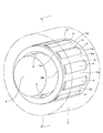
図1〜2は、請求項1、2に対応する、本発明の実施例1を示している。尚、本実施例の特徴は、支持軸5の周囲にタペットローラ6を回転自在に支持する為のラジアルニードル軸受7cの構造に関する。上記支持軸5の両端部をロッカーアーム3の支持壁部4、4(図6〜8参照)に支持固定する部分等、上記ラジアルニードル軸受7c以外の部分の構造及び作用は、前述の図6〜8に示した従来構造の場合と同様であるから、重複する図示並びに説明は、省略若しくは簡略にし、以下、本実施例の特徴部分を中心に説明する。
1 and 2 show a first embodiment of the present invention corresponding to
本実施例の場合、上記ラジアルニードル軸受7cを構成する12本のニードル8、8を、籠形の保持器10bにより、転動自在に保持している。この保持器10bは、合成樹脂を射出成形する事により一体に造られたもので、それぞれが円環状で互いに平行に且つ同心に配置された1対のリム部11、11と、上記支持軸5と平行に配置された状態で、これら両リム部11、11の内側面同士の間に掛け渡された、保持すべきニードル8、8と同数(12本)の柱部12、12とから成る。尚、上記合成樹脂の種類に就いては特に限定しない。ポリアミド樹脂、ポリフェニレンサルファイド樹脂等、一般的に保持器を造る場合に使用している各種合成樹脂を採用できる。例えば、補強材としてガラス繊維を20〜30重量%(好ましくは25重量%)含有するポリアミド46は、150℃程度まで使用可能な耐熱性を有する為、エンジンの動弁機構に使用するカムフォロア装置に組み込むのに適している。一方、ポリアミド66は、安価でしかも優れた成形性を有する為、低コスト化の面から有利である。但し、上記範囲のガラス繊維を補強材として含有させたとしても、120℃程度の耐熱性しか得られないので、使用条件を考慮する必要がある。
In the case of the present embodiment, twelve
本実施例の場合、上記両リム部11、11の内径R11を上記支持軸5の外径D5 よりも僅かに大きく(R11>D5 )している。又、これら両リム部11、11の外径D11を、上記タペットローラ6の内径R6 よりも十分に小さく(D11≪R6 )、上記各ニードル8、8のピッチ円直径DP8と同じか、このピッチ円直径DP8よりも僅かに大きい程度(D11≧DP8)にしている。更に、上記各柱部12、12の外周側面と上記両リム部11、11の外周縁とは単一円筒面上に、これら各柱部12、12の内周側面とこれら両リム部11、11の内周縁とは単一円筒面上に、それぞれ位置させている。従って、上記保持器10bの径方向に関する、上記各柱部12、12厚さ寸法T12は、上記両リム部11、11の幅寸法W11と等しい(T12=W11)。
In this embodiment, it is slightly larger (R 11> D 5) than the outer diameter D 5 of the supporting
又、上記各柱部12、12の外径側端部で、上記各ニードル8、8のピッチ円P上に位置し、円周方向に隣り合うニードル8、8同士の間に位置する部分の円周方向に関する幅寸法w12は、内径寄り部分の幅寸法W12よりも小さく(w12<W12)している。この構成により、上記各柱部12、12の断面積を確保し、これら各柱部12、12の強度及び剛性を確保しつつ、円周方向に隣り合うニードル8、8の転動面同士を近づけられる様にしている。更に、上記両リム部11、11の内周縁及び上記各柱部12、12の内周側面を、上記支持軸5の外周面に近接対向させる事により、上記保持器10bの径方向に関する位置決めを(所謂内輪案内により)図っている。
Further, at the outer diameter side end of each of the
本実施例は、上述の様な構成により、円周方向に隣り合うニードル8、8の転動面同士が擦れ合う事を防止しつつ、これら各ニードル8、8の本数が過度に少なくならない様にしている。即ち、前述の図10に示す様に総ニードル構造で15本程度のニードル8、8を組み込める部分を考えた場合、前述の図13に示した様に、従来から一般的に使用されている保持器10、10aを使用すると、10本程度のニードル8、8しか組み込めなかった。これに対して本実施例の場合には、上述した通り、12本程度のニードル8、8を組み込める。又、上記両リム部11、11を設ける事により、前記支持壁部4、4の内側面の摩耗を抑えられる様にしている。
In the present embodiment, the configuration as described above prevents the rolling surfaces of the
上述の様に構成する本実施例のカムフォロア装置の場合、円周方向に隣り合うニードル8、8同士の間に、上記保持器10bの柱部12、12が存在する為、これら各ニードル8、8の転動面同士が擦れ合う事がない。これら各ニードル8、8の転動面と各柱部12、12の円周方向側面とは擦れ合うが、これら各柱部12、12は、上記各ニードル8、8の様な自転運動をする事はない為、擦れ合い速度は、円周方向に隣り合うニードル8、8の転動面同士が擦れ合う場合に比べて遅い(1/2に抑えられる)。又、合成樹脂製の保持器10bを構成する、上記各柱部12、12の円周方向側面と、上記各ニードル8、8の転動面との摺接部の摩擦係数は、ニードル8、8の転動面同士が擦れ合った場合の摩擦係数に比べて低く抑えられる。この為、前記ラジアルニードル軸受7cの動トルクを低く抑えて、前記タペットローラ6の回転抵抗を低く抑えられる。この結果、本実施例のカムフォロア装置を組み込んだエンジンの燃料消費量を低減する等、このエンジンの性能向上を図れる。
In the case of the cam follower device of the present embodiment configured as described above, since the
更に、上記各柱部12、12の厚さ寸法T12は、上記各ニードル8、8の直径D8 よりも小さく、しかも、径方向に関する位置をこれら各ニードル8、8のピッチ円直径に対して径方向内側に偏らせている為、円周方向に隣り合うニードル8、8の転動面同士の距離を、上記各柱部12、12の円周方向に関する幅寸法よりも近づける事ができる。そして、前記支持軸5の外周面と上記タペットローラ6の内周面との間に配置するニードル8、8の数(12本)を確保できる。この結果、このタペットローラ6の厚さ寸法T6 を特に大きくしなくても、エンジンの運転時にこのタペットローラ6に生じる曲げ応力を小さく抑えて、このタペットローラ6の損傷防止を図れる。又、合成樹脂製の保持器10bは、成形が容易で安価に得られる他、軽量である為、本実施例のカムフォロア装置を組み込んだエンジンの低コスト化、高性能化の面から有利である。
Furthermore, the thickness T 12 of the
図3〜4は、請求項1〜3に対応する、本発明の実施例2を示している。本実施例の場合、保持器10cを構成する1対のリム部11a、11a及びこれら両リム部11a、11a同士の間に設けられた柱部12a、12aを、各ニードル8、8のピッチ円Pに対しし、径方向外側に配置している。これら各柱部12a、12aの径方向外端部の幅寸法は内径寄り部分の幅寸法よりも大きくして、円周方向に隣り合う柱部12a、12aの外径側端部の円周方向端縁同士の距離を、上記各ニードル8、8の外径よりも十分に小さくしている。そして、上記両リム部11a、11aの外周縁及び上記各柱部12a、12aの外周側面をタペットローラ6の内周面に近接対向させて、上記保持器10cの径方向位置を(所謂外輪案内により)規制している。又、上記各柱部12a、12aの径方向内端部を上記ピッチ円Pよりも少しだけ径方向内方に位置させると共に、円周方向に隣り合う柱部12a、12aの内径側端部の円周方向端縁同士の距離を、上記各ニードル8、8の外径よりも少しだけ小さくしている。
FIGS. 3-4 shows Example 2 of this invention corresponding to Claims 1-3. In the case of the present embodiment, the pair of
この様な本実施例の場合、上記保持器10cのポケット13、13内に上記各ニードル8、8を、この保持器10cの径方向内側から組み込む。この際、円周方向に隣り合う上記各柱部12a、12aを弾性変形させて、これら各柱部12a、12aの内径側端部同士の円周方向に関する間隔を広げる。上記各ポケット13、13内に上記各ニードル8、8を組み込んだ後の状態では、上記各柱部12a、12aの内径側端部同士の円周方向に関する間隔が縮まって、上記各ニードル8、8が上記各ポケット13、13内から不用意に脱落する事がなくなる。この為、上記保持器10cと、この保持器10cに保持される複数本のニードル8、8とを不離に結合した、所謂ケージ&ローラとして取り扱える為、部品管理の簡略化やカムフォロア装置の組立性の向上を図れる。又、上記保持器10cの径方向位置を外輪案内により規制している為、この保持器10cの外周面と上記タペットローラ6の内周面との擦れ合い部に十分量の潤滑油を介在させる事ができる。即ち、カムフォロア装置の運転時に潤滑油は、遠心力によって上記タペットローラ6の内周面に集まる。この為、上記保持器10cの外周面と上記タペットローラ6の内周面との擦れ合い部の摩擦を低減して、これら両周面の摩耗を抑えられる。その他の部分の構成及び作用は、前述した実施例1と同様である。
In the case of this embodiment, the
尚、本実施例の変形として、上記各柱部12a、12aの内周側面位置を、図4に示した位置よりも少し径方向外側(ピッチ円Pよりも外径側)に位置させる事もできる。この様な構成を採用した場合には、各ポケット内に組み込んだニードル8、8が、支持軸5の組み付け前に径方向内方に抜け出る事を防止する事はできないが、円周方向に隣り合うニードル8、8同士の間隔を縮めて、上記支持軸5の外周面とタペットローラ6の内周面との間に組み込めるニードル8、8の数を増やす事が可能になる。この様な構造は、前述の実施例1に対し、ニードル8、8のピッチ円Pに関して、ニードル8、8及び保持器を径方向反対側に移した如き構造になる。ニードル8、8の数及びピッチ円直径が同じである場合、円周方向に隣り合うニードル8、8同士の間に存在する隙間は、ピッチ円Pの内径側よりも外径側が大きい。従って、上述の様な構造は、柱部の断面積を確保する面からは有利である。
As a modification of the present embodiment, the inner peripheral side surface position of each of the
又、本実施例の変形として、図5に示す様に、ポケット13の外径側開口部と内径側開口部とに係止突片17a、17bを、このポケット13側に突出する状態で形成し、これら各係止突片17a、17bにより、このポケット13内からのニードル8の脱落防止を図る事もできる。このポケット13内にこのニードル8を組み込む際には、何れかの係止突片17a(17b)を円周方向に弾性変形させつつ、上記ポケット13内に上記ニードル8を押し込む。
Further, as a modification of the present embodiment, as shown in FIG. 5, locking
尚、本発明を実施する場合に、支持軸5の外周面と各ニードル8、8の転動面とのうちの少なくとも一方の面に、浸炭窒化層を形成する事は、これら外周面及び転動面の損傷を防止して、カムフォロア装置の耐久性向上を図る面から有効である。図14は、この様な浸炭窒化層を形成する事による効果を確認する為の実験に使用した装置を示している。この実験装置では、ヘッド14に支持した支持軸5の周囲にラジアルニードル軸受7により回転自在に支持したタペットローラ6を、カムに対応するリング15の外周面に、所望の荷重により押圧自在としている。又、このリング15の下端部は、装置の下部に貯溜された潤滑油16中に浸漬している。実験を行なう際には、上記タペットローラ6を上記リング15の外周面に所定の押圧力により押圧しつつ、このリング15を所望の回転速度で回転させる。そして、上記ラジアルニードル軸受7に、剥離に基づく損傷が発生し、その結果、著しい振動が発生する迄の時間(寿命)を測定した。
In carrying out the present invention, a carbonitriding layer is formed on at least one of the outer peripheral surface of the
この様にして行なった実験の結果を、図15に示す。この図15の横軸は上記ラジアルニードル軸受7の寿命を、竪軸は複数の試料のうちで寿命に達した試料の割合を、それぞれ表している。この様な図15にその結果を示した実験には、前述の図9〜10に示す様な、総ニードル型のラジアルニードル軸受7を使用した。又、上記リング15の回転速度は5000min-1 、付加荷重は0.3C、使用した潤滑油16は5W−20のエンジンオイル、この潤滑油16の温度は100℃とした。この様な条件で行なった実験の結果を示す図15中、実線aは、上記支持軸5と上記各ニードル8、8とに、標準的な熱処理(所謂ズブ焼きによる焼き入れ)を施した場合を、破線bは、これら支持軸5と各ニードル8、8とに、浸炭窒化処理を施した(表面及び転動面に浸炭窒化層を形成した)場合を、それぞれ示している。
The results of the experiment conducted in this way are shown in FIG. The horizontal axis in FIG. 15 represents the life of the
この様な実験結果から明らかな通り、上記支持軸5と上記各ニードル8、8とに浸炭窒化処理を施す事で、標準的な熱処理を施した場合に比べて、寿命を凡そ7倍に延長できる。この様に寿命を延長できる為、仮に、保持器或いはセパレータを設けてニードルの数が少なくなる事に伴って耐久性が低下する傾向になっても、上記支持軸5と上記各ニードル8、8とに浸炭窒化処理を施す事により、この耐久性低下を十分に補える。尚、浸炭窒化処理は、上記支持軸5と上記各ニードル8、8との両方に施す事が好ましいが、片方にのみ施すだけでも、或る程度の効果を得られる。従って、コストと、必要とされる耐久性とを考慮しつつ、浸炭窒化処理を施すか否か、施すとすれば、何れの部分に施すかを決定する。尚、前記タペットローラ6に就いては、必ずしも浸炭窒化処理を施す必要はないが、より優れた耐久性を得る為に、施す事は自由である。
As is clear from the experimental results, the life of the
1 カムシャフト
2 カム
3 ロッカーアーム
4 支持壁部
5、5a、5b 支持軸
6 タペットローラ
7、7a、7b、7c ラジアルニードル軸受
8 ニードル
9、9a ローラ
10、10a、10b、10c 保持器
11、11a リム部
12、12a 柱部
13 ポケット
14 ヘッド
15 リング
16 潤滑油
17a、17b 係止突片
DESCRIPTION OF
Claims (5)
Priority Applications (3)
| Application Number | Priority Date | Filing Date | Title |
|---|---|---|---|
| JP2005005909A JP2006194139A (en) | 2005-01-13 | 2005-01-13 | Cam follower device |
| PCT/JP2006/300287 WO2006075658A1 (en) | 2005-01-13 | 2006-01-12 | Cam follower device |
| US11/813,932 US20090050091A1 (en) | 2005-01-13 | 2006-02-12 | Cam follower apparatus |
Applications Claiming Priority (1)
| Application Number | Priority Date | Filing Date | Title |
|---|---|---|---|
| JP2005005909A JP2006194139A (en) | 2005-01-13 | 2005-01-13 | Cam follower device |
Publications (2)
| Publication Number | Publication Date |
|---|---|
| JP2006194139A true JP2006194139A (en) | 2006-07-27 |
| JP2006194139A5 JP2006194139A5 (en) | 2007-09-06 |
Family
ID=36800423
Family Applications (1)
| Application Number | Title | Priority Date | Filing Date |
|---|---|---|---|
| JP2005005909A Pending JP2006194139A (en) | 2005-01-13 | 2005-01-13 | Cam follower device |
Country Status (1)
| Country | Link |
|---|---|
| JP (1) | JP2006194139A (en) |
Cited By (7)
| Publication number | Priority date | Publication date | Assignee | Title |
|---|---|---|---|---|
| JP2009293603A (en) * | 2008-06-09 | 2009-12-17 | Ntn Corp | Cam follower for rocker arm, and cam follower device |
| US8991351B2 (en) | 2013-03-15 | 2015-03-31 | Roller Bearing Company Of America, Inc. | Needle roller cam follower for higher mileage applications of light, medium and heavy duty vehicles |
| WO2016035373A1 (en) * | 2014-09-02 | 2016-03-10 | 株式会社リケン | Roller-type rocker arm |
| JP2016089924A (en) * | 2014-11-04 | 2016-05-23 | Ntn株式会社 | Synthetic resin made cage and ball bearing |
| JP2016156298A (en) * | 2015-02-24 | 2016-09-01 | 株式会社リケン | Roller type locker arm |
| JP2016200211A (en) * | 2015-04-10 | 2016-12-01 | 株式会社オティックス | Rolling bearing |
| DE102017010191A1 (en) | 2017-01-05 | 2018-07-05 | Kamoseiko Kabushiki Kaisha | bearing device |
-
2005
- 2005-01-13 JP JP2005005909A patent/JP2006194139A/en active Pending
Cited By (11)
| Publication number | Priority date | Publication date | Assignee | Title |
|---|---|---|---|---|
| JP2009293603A (en) * | 2008-06-09 | 2009-12-17 | Ntn Corp | Cam follower for rocker arm, and cam follower device |
| US8991351B2 (en) | 2013-03-15 | 2015-03-31 | Roller Bearing Company Of America, Inc. | Needle roller cam follower for higher mileage applications of light, medium and heavy duty vehicles |
| WO2016035373A1 (en) * | 2014-09-02 | 2016-03-10 | 株式会社リケン | Roller-type rocker arm |
| JPWO2016035373A1 (en) * | 2014-09-02 | 2017-06-15 | 株式会社リケン | Roller type rocker arm |
| US10280813B2 (en) | 2014-09-02 | 2019-05-07 | Kabushiki Kaisha Riken | Roller-type rocker arm |
| JP2016089924A (en) * | 2014-11-04 | 2016-05-23 | Ntn株式会社 | Synthetic resin made cage and ball bearing |
| JP2016156298A (en) * | 2015-02-24 | 2016-09-01 | 株式会社リケン | Roller type locker arm |
| WO2016136696A1 (en) * | 2015-02-24 | 2016-09-01 | 株式会社リケン | Roller-type rocker arm |
| JP2016200211A (en) * | 2015-04-10 | 2016-12-01 | 株式会社オティックス | Rolling bearing |
| DE102017010191A1 (en) | 2017-01-05 | 2018-07-05 | Kamoseiko Kabushiki Kaisha | bearing device |
| KR20180080979A (en) | 2017-01-05 | 2018-07-13 | 가모세이코 가부시키가이샤 | A bearing device |
Similar Documents
| Publication | Publication Date | Title |
|---|---|---|
| JP2006194139A (en) | Cam follower device | |
| JP5845662B2 (en) | Single row deep groove type radial ball bearing | |
| JP2006226400A (en) | Shaft device | |
| JP2006226318A (en) | One-way clutch built-in pulley device | |
| WO2006075658A1 (en) | Cam follower device | |
| JP4929605B2 (en) | Rolling bearing and camshaft device | |
| JP4464767B2 (en) | Roller with cage | |
| JP5515475B2 (en) | Bearing device for tappet roller | |
| JP2011241894A (en) | Split rolling bearing, and bearing device with the same | |
| JP2014001748A (en) | Stroke shaped linear ball bearing | |
| JP2007024207A (en) | Needle roller bearing | |
| JP2012241774A (en) | Rotation body and rocker arm | |
| JP2011133081A (en) | Split rolling bearing device | |
| JP2011169154A (en) | Pump tappet | |
| JP2006200441A (en) | Cam follower device | |
| JP2010196861A (en) | Roll bearing | |
| JP2009293603A (en) | Cam follower for rocker arm, and cam follower device | |
| JP2007303598A (en) | Two piece roller bearing | |
| JP4935447B2 (en) | Rolling bearing | |
| JP2009014014A (en) | Roller bearing | |
| JP2008082421A (en) | Solid-shaped needle-like roller bearing and method of manufacturing cage of solid-shaped needle-like roller bearing | |
| JP5476593B2 (en) | Shell needle bearing | |
| JP2007270948A (en) | Divided roller bearing | |
| JP2009180235A (en) | Automatic self-aligning roller bearing | |
| JP2003222006A (en) | Cam follower device |
Legal Events
| Date | Code | Title | Description |
|---|---|---|---|
| RD04 | Notification of resignation of power of attorney |
Free format text: JAPANESE INTERMEDIATE CODE: A7424 Effective date: 20070501 |
|
| A521 | Written amendment |
Free format text: JAPANESE INTERMEDIATE CODE: A523 Effective date: 20070724 |
|
| A621 | Written request for application examination |
Free format text: JAPANESE INTERMEDIATE CODE: A621 Effective date: 20070724 |
|
| A131 | Notification of reasons for refusal |
Free format text: JAPANESE INTERMEDIATE CODE: A131 Effective date: 20090303 |
|
| A02 | Decision of refusal |
Free format text: JAPANESE INTERMEDIATE CODE: A02 Effective date: 20090707 |