JP4464767B2 - Roller with cage - Google Patents
Roller with cage Download PDFInfo
- Publication number
- JP4464767B2 JP4464767B2 JP2004246396A JP2004246396A JP4464767B2 JP 4464767 B2 JP4464767 B2 JP 4464767B2 JP 2004246396 A JP2004246396 A JP 2004246396A JP 2004246396 A JP2004246396 A JP 2004246396A JP 4464767 B2 JP4464767 B2 JP 4464767B2
- Authority
- JP
- Japan
- Prior art keywords
- cage
- roller
- inner peripheral
- curved surface
- circumferential
- Prior art date
- Legal status (The legal status is an assumption and is not a legal conclusion. Google has not performed a legal analysis and makes no representation as to the accuracy of the status listed.)
- Active
Links
Images


Classifications
-
- F—MECHANICAL ENGINEERING; LIGHTING; HEATING; WEAPONS; BLASTING
- F16—ENGINEERING ELEMENTS AND UNITS; GENERAL MEASURES FOR PRODUCING AND MAINTAINING EFFECTIVE FUNCTIONING OF MACHINES OR INSTALLATIONS; THERMAL INSULATION IN GENERAL
- F16C—SHAFTS; FLEXIBLE SHAFTS; ELEMENTS OR CRANKSHAFT MECHANISMS; ROTARY BODIES OTHER THAN GEARING ELEMENTS; BEARINGS
- F16C19/00—Bearings with rolling contact, for exclusively rotary movement
- F16C19/22—Bearings with rolling contact, for exclusively rotary movement with bearing rollers essentially of the same size in one or more circular rows, e.g. needle bearings
- F16C19/44—Needle bearings
- F16C19/46—Needle bearings with one row or needles
- F16C19/463—Needle bearings with one row or needles consisting of needle rollers held in a cage, i.e. subunit without race rings
-
- F—MECHANICAL ENGINEERING; LIGHTING; HEATING; WEAPONS; BLASTING
- F16—ENGINEERING ELEMENTS AND UNITS; GENERAL MEASURES FOR PRODUCING AND MAINTAINING EFFECTIVE FUNCTIONING OF MACHINES OR INSTALLATIONS; THERMAL INSULATION IN GENERAL
- F16C—SHAFTS; FLEXIBLE SHAFTS; ELEMENTS OR CRANKSHAFT MECHANISMS; ROTARY BODIES OTHER THAN GEARING ELEMENTS; BEARINGS
- F16C33/00—Parts of bearings; Special methods for making bearings or parts thereof
- F16C33/30—Parts of ball or roller bearings
- F16C33/46—Cages for rollers or needles
- F16C33/4617—Massive or moulded cages having cage pockets surrounding the rollers, e.g. machined window cages
- F16C33/4623—Massive or moulded cages having cage pockets surrounding the rollers, e.g. machined window cages formed as one-piece cages, i.e. monoblock cages
- F16C33/4629—Massive or moulded cages having cage pockets surrounding the rollers, e.g. machined window cages formed as one-piece cages, i.e. monoblock cages made from metal, e.g. cast or machined window cages
-
- F—MECHANICAL ENGINEERING; LIGHTING; HEATING; WEAPONS; BLASTING
- F16—ENGINEERING ELEMENTS AND UNITS; GENERAL MEASURES FOR PRODUCING AND MAINTAINING EFFECTIVE FUNCTIONING OF MACHINES OR INSTALLATIONS; THERMAL INSULATION IN GENERAL
- F16C—SHAFTS; FLEXIBLE SHAFTS; ELEMENTS OR CRANKSHAFT MECHANISMS; ROTARY BODIES OTHER THAN GEARING ELEMENTS; BEARINGS
- F16C2360/00—Engines or pumps
- F16C2360/22—Internal combustion engines
-
- F—MECHANICAL ENGINEERING; LIGHTING; HEATING; WEAPONS; BLASTING
- F16—ENGINEERING ELEMENTS AND UNITS; GENERAL MEASURES FOR PRODUCING AND MAINTAINING EFFECTIVE FUNCTIONING OF MACHINES OR INSTALLATIONS; THERMAL INSULATION IN GENERAL
- F16C—SHAFTS; FLEXIBLE SHAFTS; ELEMENTS OR CRANKSHAFT MECHANISMS; ROTARY BODIES OTHER THAN GEARING ELEMENTS; BEARINGS
- F16C9/00—Bearings for crankshafts or connecting-rods; Attachment of connecting-rods
- F16C9/04—Connecting-rod bearings; Attachments thereof
Description
この発明は,主にエンジン用部品に使用され,特に,エンジンのコネクティングロッドの大端部に使用される保持器付きころに関する。 The invention is mainly used parts for engines, in particular, it relates to a retainer with this filtrate to be used in the large end of the connecting rod of the engine.
従来,エンジンのコネクティングロッドの大端部に使用される保持器付きころは,保持器の内周に略U字状の凹部が形成された門形形状になっている。該保持器付きころは,両端の円環部と該円環部に一体構造のポケットを形成した柱部を有する略円筒状の保持器と,該保持器のポケット各々に挿入されたころとから成り,ころの脱落を防止する外側保持用突出部を柱部の一部にポケットに突出して形成し,該突出部の加工により生じた凹部を全て除去すべく保持器の外周側を切削して外側保持用突出部の外面と保持器の正規外径とが一致するように加工されている。ころの保持用突出部は,外側に形成されており,その外面が保持器の外周面の位置に形成されている。また,保持器の各々の柱部は,その略全長にわたって外側面を円環部の外周面に面一とし,柱部の軸方向における中央にして円周方向における両側にポケットの一部を拡幅するように切欠部が形成され,また,外側の保持用突出部の位置を保持器の最も外周側に形成したものであり,保持器付きころをエンジンに組み込んだ場合に,保持器のころの案内部が多少摩耗したとしても,ころが外側保持用突出部に接触しないように構成し,焼付き防止を図ったものである。更に,上記保持器付きころは,外側保持用突出部の外面が保持器の外周面と面一に形成されることから,保持器の外周面の面積が大きくなり,接触面圧を小さくすることができ,焼付き防止を図ったものにもなっている。従って,上記保持器付きころは,エンジンのより高速回転に適用できるものになっている(例えば,特許文献1参照)。 2. Description of the Related Art Conventionally, a roller with a cage used at the large end of an engine connecting rod has a portal shape in which a substantially U-shaped recess is formed on the inner periphery of the cage. The roller with cage includes a substantially cylindrical cage having annular portions at both ends and a column portion in which a pocket having an integral structure is formed in the annular portion, and rollers inserted into the pockets of the cage. The outer holding projection that prevents the roller from falling off is formed in a part of the column so as to protrude into the pocket, and the outer peripheral side of the cage is cut to remove all the recesses caused by the processing of the projection. It is processed so that the outer surface of the outer holding projection and the regular outer diameter of the cage coincide. The holding projection of the roller is formed on the outer side, and the outer surface thereof is formed at the position of the outer peripheral surface of the cage. In addition, each column of the cage has an outer surface that is flush with the outer circumferential surface of the annular portion over almost the entire length, and a part of the pocket is widened on both sides in the circumferential direction, with the column center being the center in the axial direction. A notch is formed on the outermost side of the cage, and the position of the outer retaining projection is formed on the outermost side of the cage. Even if the guide part is slightly worn, it is constructed so that the rollers do not contact the outer holding projection part to prevent seizure. Further, in the roller with cage, since the outer surface of the outer holding projection is formed flush with the outer circumferential surface of the cage, the area of the outer circumferential surface of the cage is increased and the contact surface pressure is reduced. It can also be used to prevent seizure. Therefore, the roller with cage is applicable to higher speed rotation of the engine (see, for example, Patent Document 1).
従来,針状ころ軸受用保持器として,ポケット案内面の精度を確保しつつ,後加工を不要とし,保持器の精度向上,製造コストの低減を図るものが知られている。該針状ころ軸受用保持器は,保持器の内周面が薄肉部の内壁面と両厚肉部の内壁面とがそれぞれ中央側に傾斜したテーパ壁面で連続し,ポケットの案内面がピッチ円P.C.D.上において剪断面に形成されている(例えば,特許文献2参照)。 Conventionally, as a cage for a needle roller bearing, there has been known one that ensures the accuracy of the pocket guide surface, eliminates the need for post-processing, improves the accuracy of the cage, and reduces the manufacturing cost. In the cage for needle roller bearings, the inner peripheral surface of the cage is continuous with a tapered wall surface in which the inner wall surface of the thin wall portion and the inner wall surface of both thick wall portions are inclined toward the center, and the guide surface of the pocket is pitched. Yen P. C. D. It is formed on the shearing surface above (see, for example, Patent Document 2).
また,従来の転がり軸受の製造方法として,軸受外輪が転造加工により軌道輪が形成されたものが知られている。軌道輪の転造加工は,リング状の素材を所定の温度に加熱してオーステナイト化した後,200〜350℃の温度に急冷し,オーステナイト状態のままリング状の素材に所定の転造加工を行い,その後,Ms点以下の温度にまで冷却してマルテンサイト変態を生じさせ,硬さをHRC57以上としたものになっている(例えば,特許文献3参照)。
ところで,保持器付きころについて,エンジンの性能向上に伴って,エンジンのより高速回転に適用でき,更に安価なものが求められると共に,製造に当たって環境にやさしいものが求められている。上記の保持器付きころは,エンジン用として広く使用され,高い耐久性を発揮している。しかしながら,上記保持器付きころは,保持器がリング状の素材から旋削加工により保持器の内周が略U字状の凹部に形成された門形形状であり,エンジンにおけるコネクティングロッドの大端部用に使用した場合に,肉厚変化が大きく,コネクティングロッド大端部の内周面との面当りがきついものになっていた。また,保持器をリング状の素材から旋削加工するため,加工時間を要し,切屑が多数発生して該切屑の廃棄が必要であり,材料が無駄になっているのが現状である。更に,上記保持器は,リング状の素材から旋削加工により製作されるが,略U字状の凹部が門形形状で角ばっており,加工し難いという問題を有していた。 By the way, with respect to the roller with cage, as the engine performance is improved, a roller that can be applied to a higher speed rotation of the engine and that is cheaper is required, and an environment-friendly one is required for manufacturing. The above roller with cage is widely used for engines and exhibits high durability. However, the roller with a cage has a portal shape in which the cage is formed by turning a ring-shaped material into a substantially U-shaped recess by turning, and the large end portion of the connecting rod in the engine. When used for a large number, the wall thickness change was large and the contact with the inner peripheral surface of the connecting rod large end was tight. In addition, since the cage is turned from a ring-shaped material, it takes a long time, a large amount of chips are generated, and it is necessary to discard the chips, and the material is wasted. Further, the cage is manufactured by turning from a ring-shaped material, but has a problem that it is difficult to process because the substantially U-shaped recess is square in a gate shape.
また,上記針状ころ軸受用保持器は,上記の保持器付きころと同様に,内周面が薄肉部の内壁面と両厚肉部の内壁面とが,それぞれ中央側に傾斜したテーパ壁面で連続した形状に形成されているので,コネクティングロッド大端部の内周面との面当りが若干きつい傾向になっており,また,保持器の内周面は,薄肉部の内壁面と両厚肉部の内壁面とがそれぞれ中央側に傾斜したテーパ壁面で連続した形状,即ち,直線的になって角ばっているので,加工し難い形状であり,保持器がころを保持する構成になっていないので,取り扱い難いものになっている。 Also, the cage for the needle roller bearing is a tapered wall surface in which the inner wall surface of the thin wall portion and the inner wall surfaces of both thick wall portions are inclined toward the center, respectively, in the same manner as the roller with the roller cage. The contact with the inner peripheral surface of the large end of the connecting rod tends to be slightly tight, and the inner peripheral surface of the cage The inner wall surface of the thick wall part is a continuous shape with a tapered wall surface inclined to the center side, that is, it is straight and square, so it is difficult to machine, and the cage holds the rollers. Because it is not, it is difficult to handle.
また,上記の転がり軸受の製造方法は,軌道輪を転造加工によって作製するものであり,高度な転造加工方法を採用しなければ,軌道輪を高精度な形状に作製できないものである。 In addition, the rolling bearing manufacturing method described above is to produce the race ring by rolling, and the race ring cannot be produced in a highly accurate shape unless an advanced rolling process is adopted.
この発明の目的は,上記の課題を解決するため,エンジンのより高速回転に適用でき,安価なものにするために,本出願人が開発した上記の保持器付きころを更に発展させたものであり,初期工程で素材を削り出す旋削加工,或いは旋削加工に代わって転造加工で形成できる形状及び内側保持爪の形状に特徴を有するものであり,また,保持器を転造加工によって形成した場合には,保持器を形成する材料の無駄をなくし,加工時間を短縮し,切屑を出すこと無く,最少量の材料から安価に且つ環境にやさしい加工工程で形成でき,更に保持器をエンジンの性能アップに伴ってそれに対応できる高速回転に適合する形状に形成した保持器付きころを提供することである。 The object of the present invention is to further develop the above-mentioned roller with a cage developed by the present applicant in order to solve the above-mentioned problems and to be applicable to higher speed rotation of the engine and to make it inexpensive. Yes, it is characterized by the shape that can be formed by the turning process that cuts the material in the initial process, or by the rolling process instead of the turning process, and the shape of the inner holding claw, and the cage is formed by the rolling process In some cases, the material forming the cage is eliminated, processing time is shortened, chips can be formed from a minimum amount of material at low cost and in an environmentally friendly processing process, and the cage can be it is to provide a cage with this filtrate formed in a shape adapted to the high speed to cope with it with the performance improvement.
この発明は,軸方向に隔置して周方向に平行に延びる両端の円環部と該円環部間で周方向に隔置してそれぞれ延びる前記円環部と一体構造の柱部とから構成されている保持器,及び前記柱部間に形成されたポケットにそれぞれ収容されたころから成るエンジンのコネクティングロッドの大端部に適用される保持器付きころにおいて,
前記保持器は,外周面が軸方向に面一に形成され,前記コネクティングロッドの前記大端部の内周面と前記柱部の前記外周面との面当たりを前記軸方向に沿って一様にするために,前記保持器の内周面の前記軸方向の中央に形成された内周凹部は縦断面で見て単一半径の曲面に成る凹曲面の形状に形成され,且つ前記凹曲面の底直径が前記ころのピッチ円直径より大きく形成されて,前記柱部は両端の厚肉部と該厚肉部間の漸減肉部から形成され,前記保持器の前記内周面を前記凹曲面に形成することにより転造加工が可能に且つ軽量化が可能に構成され,
前記柱部には,前記厚肉部と前記厚肉部に隣接する前記漸減肉部の一部との前記柱部の円周方向両側面が前記ころを案内するころ案内部に形成され,前記柱部の軸方向中央の円周方向両側に前記ポケットの一部を拡幅する拡幅部が形成され,且つ前記ころの外側への脱落を防止する外側保持爪が前記厚肉部に形成され,前記外側保持爪の外周側は前記保持器の前記外周面と面一に形成されていることを特徴とする保持器付きころに関する。
The present invention includes an annular portion at both ends extending in parallel in the circumferential direction and spaced apart in the axial direction, and the annular portion extending in a circumferential direction between the annular portions and the pillar portion having an integral structure. A roller with a cage that is applied to a large end portion of a connecting rod of an engine comprising a cage and rollers that are respectively housed in pockets formed between the pillars;
The retainer has an outer circumferential surface that is flush with the axial direction, and the contact between the inner circumferential surface of the large end portion of the connecting rod and the outer circumferential surface of the column portion is uniform along the axial direction. In order to achieve this, the inner peripheral recess formed in the axial center of the inner peripheral surface of the cage is formed in the shape of a concave curved surface that is a curved surface having a single radius when viewed in a longitudinal section , and the concave curved surface A bottom diameter of the roller is larger than a pitch circle diameter of the roller, and the column part is formed of a thick part at both ends and a gradually reduced thickness part between the thick parts, and the inner peripheral surface of the cage is recessed in the concave part. By forming it on a curved surface, it can be rolled and made lightweight.
In the column part, both circumferential side surfaces of the column part of the thick part and a part of the gradually decreasing thickness part adjacent to the thick part are formed in a roller guide part for guiding the roller, widened portion formed for widening a portion of the pocket on both sides in the circumferential direction of the axial center of the pillar portion, the outer holding claw for preventing detachment of the outer且previous SL rollers is formed in the thick portion , A roller with a cage, wherein the outer circumferential side of the outer holding claw is formed flush with the outer circumferential surface of the cage.
この発明による保持器付きころは,上記のように,保持器の内周面の内周凹部が凹曲面に形成されているので,凹曲面が旋削加工や転造加工がし易い形状であって保持器を安価に製作でき,エンジンのコネクティングロッドの大端部に適用した場合に,エンジンの高速化に対応できる性能を発揮でき,エンジンのより高速回転に最適な形状に構成され,保持器の外周面の面当りをなめらかにし,保持器の重量を軽減して保持器の面当りを小さくし,しかも,エンジンのコネクティングロッドに組み込む際に,保持器の外側保持爪と内側保持爪とによってころを回転自在に保持でき,保持器からころが脱落することが無い状態で組み立てしやすくなり,更に,コネクティングロッド大端部では保持器に遠心力と回転とが同時に作用することから保持器は外周案内されるので,特に,保持器の内周凹部を凹曲面に形成して外周面の面当りをなめらかにし,可能なかぎり保持器の重量を軽減して面当りが小さくなるように構成され,従来よりもエンジンの高速回転に適合できるものになっている。 In the roller with cage according to the present invention, as described above, since the inner circumferential concave portion of the inner circumferential surface of the cage is formed into a concave curved surface, the concave curved surface has a shape that is easy to be turned or rolled. The cage can be manufactured at a low cost, and when applied to the large end of the connecting rod of the engine, it can exhibit the performance that can cope with the high speed of the engine, and is configured in an optimum shape for higher speed rotation of the engine. Smoothen the perimeter of the outer surface, reduce the weight of the cage to reduce the surface perimeter of the cage, and when assembled into the connecting rod of the engine, the rollers are held by the outer and inner retaining claws of the cage. Because it is easy to assemble without the rollers falling off from the cage, centrifugal force and rotation act simultaneously on the cage at the large end of the connecting rod. Since the cage is guided to the outer periphery, the inner peripheral recess of the cage is formed into a concave curved surface to smooth the contact of the outer peripheral surface and reduce the weight of the cage as much as possible to reduce the contact. It can be adapted to high-speed engine rotation than before.
また,この保持器付きころについて,保持器を転造加工によって作製した場合には,従来の旋削加工によって作製された保持器に比較して,素材を最小限に低減して安価に作製でき,転造加工により保持器素材の内周面がロールによる圧印による押し付けによって保持器そのものの剛性や強度を確保でき,保持器の加工に当たって切り屑等が発生せずに環境にやさしい加工品を作製でき,更に,保持器の内周面を転造加工できる形状,即ち,保持器の内周面の内周凹部を半環状の凹曲面に形成し,内側保持爪を転造加工が可能になる保持器の内周面と面一の位置に形成し,しかも内側保持爪がエンジンの高速回転時にころに接触し難い構造になってエンジン性能に悪影響を及ぼさない形状に構成される。 In addition, for this roller with cage, when the cage is manufactured by rolling, it can be manufactured at a low cost by minimizing the material compared to the cage manufactured by conventional turning. Rolling process can secure the rigidity and strength of the cage itself by pressing the inner peripheral surface of the cage material with the impression by the roll, and it is possible to produce an environment-friendly processed product without generating chips during machining of the cage. Furthermore, the shape that allows the inner peripheral surface of the cage to be rolled, that is, the inner peripheral recess of the inner peripheral surface of the cage is formed into a semi-annular concave curved surface, and the inner holding claw can be rolled. It is formed in a position that is flush with the inner peripheral surface of the vessel, and the inner holding claw is structured so as not to contact the roller during high-speed rotation of the engine, so that the engine performance is not adversely affected.
従って,この保持器付きころは,保持器そのものの剛性,強度等の性能を向上させ,加工時間を短縮し,切屑を出すこと無く最少量の材料から製作され,保持器そのものの強度を確保でき,安価で環境にやさしいものになっている。また,この保持器付きころは,保持器の内周面に内側保持爪を形成する時に,転造加工と同時に内周突部を形成し,その内周突部を押し潰して保持器の内周面と面一に成形加工することによって内側保持爪が容易に形成され,また,内側保持爪が保持器の内周面と面一の位置に形成されているので,従来の保持器付きころと比較して,ころが内側保持爪に接触し難いものになっており,その接触し難いということは,エンジンの高速回転において,保持器が焼き付き難いものになり,従来よりも性能を向上させるものになっている。 Therefore, this roller with cage improves the performance of the cage itself such as rigidity and strength, shortens the processing time, and is manufactured from a minimum amount of material without generating chips, ensuring the strength of the cage itself. , It is cheap and environmentally friendly. This roller with cage also forms an inner circumferential protrusion at the same time as the rolling process when forming the inner retaining claw on the inner circumferential surface of the cage, and crushes the inner circumferential protrusion to The inner retainer claw is easily formed by molding to the peripheral surface, and the inner retainer claw is formed at the same position as the inner peripheral surface of the cage. Compared to the above, the roller is less likely to contact the inner holding claw, which means that the retainer is less likely to seize at high engine speeds and improves performance compared to the past. It is a thing.
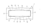
以下,図面を参照して,この発明による保持器付きころの実施例を説明する。図1〜図4を参照して,この発明による保持器付きころの第1実施例を説明する。この保持器付きころは,主として,軸方向に隔置して周方向に平行に延びる一対の円環部3と,円環部3間で周方向に隔置してそれぞれ延びる多数の柱部4とから一体構造に形成された保持器1,及び柱部4間にそれぞれ形成された柱部4と同数のポケット5に収容された針状ころでなるころ2から構成されている。一対の円環部3の側面15は,保持器1の端面を構成して互いに平行に形成されている。
Hereinafter, with reference to the drawings, an embodiment of the retainer with this filtrate according to the invention. A first embodiment of the roller with cage according to the present invention will be described with reference to FIGS. This roller with cage is mainly composed of a pair of
保持器1は,略円筒状に形成され,複数のポケット5が軸方向に平行に且つ円周方向に等間隔に柱部4間に形成されている。ポケット5の幅寸法は,保持用突出部である外側保持爪6間の寸法を除いて,ころ2の外径寸法より僅かに大きく設定されている。また,各ころ2の直径は,保持器1の肉厚よりも大となっている。各柱部4は,略全長にわたって軸方向の外側面24が両円環部3の軸方向の外周面25と面一となるように形成されている。従って,保持器1の外周面9は,ポケット5の領域を除いて完全な円筒面となり,装着される相手部材のコネクティングロッド大端部の内周面との接触面積が大になり,接触面の圧力が大幅に軽減され,発熱と接触面の摩耗の抑制に有効な構造になっている。
The
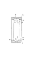
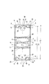
図3及び図4に示すように,保持器1における柱部4の内側の内周凹部12の軸方向中央は,保持器付きころの軸方向中心Oを通る円形の保持器付きころのピッチ円直径P.C.D.よりも外側まで達し,ポケット5の長さ内に納まる断面が半径Rで略半環状即ち半ドーナツ状の内周凹部12の凹曲面18に形成されている。柱部4は,円環部3に各々連なる両端の厚肉部26と,両厚肉部26間に位置する中央部に向かって漸次に薄くなる漸減肉部27とを有する。厚肉部26と厚肉部26に隣接する一部の漸減肉部27は,円周方向両側面が平滑なころ案内部10となっている。ころ案内部10は,ころ2に円滑に摺接してころ2を案内するように構成されている。柱部4を略円形の内周凹部12に形成すれば,柱部4の外側面24と円環部3の外周面25とを互いに面一に形成した構成と相まって,柱部4が両円環部3の断面形状と共にアーチ形門のような形状になっている。保持器1が門形の断面形状を有するので,保持器1には比較的大きな断面係数が確保され,軽量にして大きな剛性が得られる。更に,保持器1のアーチ状門形断面形状の形状については,ころ2が柱部4の両端の厚肉部26と厚肉部26に隣接する一部の漸減肉部27とによって案内されるので,ころ2の倒れ即ちスキューが小さく抑えられ,ころ2の相手部材の軌道面22,23との滑りが小さくなり,発熱量も少なくなる。また,この保持器付きころは,保持器1のアーチ状門形断面形状では,円筒形の保持器付きころのピッチ円直径P.C.D.に沿った柱部4の幅寸法が比較的小さいから,ころ2の組込み本数を増やすことができ,上述のように剛性が大であるので,高負荷容量を必要とする際に用いて好適である。
As shown in FIGS. 3 and 4, the center in the axial direction of the inner
保持器1の内周側には,柱部4の両端部近傍の両厚肉部26と漸減肉部27との境界部に,内面側両側に一対の内側保持爪7が形成されている。また,保持器1の外周側には,内側保持爪7に略対応して一対の外側保持爪6が形成されている。外側保持爪6と内側保持爪7とは,ポケット5に向かって突出しており,円周方向において隣り合う柱部4の保持爪6,7同士の距離がころ2の直径よりも僅かに小さいように設定されている。従って,ころ2は,外側に向かう動きに対しては外側保持爪6で規制され,内側に向かう動きに対して内側保持爪7で規制され,保持器1からの脱落が防止される。また,各柱部4は,軸方向における中央部で且つ円周方向における両側に,ポケット5の一部を拡げる拡幅部8が形成されるように,両側の大幅部16を所定の長さの切欠によって小幅部17に形成されている。ポケット5は,中央を拡幅したことにより,保持器付きころが潤滑剤(油)を取り入れる能力が向上する。また,この保持器付きころは,ポケット5の拡幅部8を柱部4の軸方向中央に形成したことにより,コネクティングロッドの大端部に装着した場合の潤滑性が優れたものになる。
On the inner peripheral side of the
この保持器付きころは,特に,図3に示すように,保持器1の外周面9が軸方向に面一に形成され,保持器1の内周面11には,軸方向中央に,断面凹曲面でなる半環状の凹周溝でなる内周凹部12が転造加工で形成されている。また,図3及び図4に示すように,保持器1の軸方向中心Oを通る内周凹部12の底部31の最大径である内周直径,即ち,内周凹部12の底直径d1,言い換えれば,内周凹部12の底部31を周方向にそれぞれ結ぶ円形30の直径d1は,保持器付きころのピッチ円直径P.C.D.より大に形成されていることを特徴としている。内周凹部12の凹曲面18は,特に,図3に示すように,縦断面で見て(軸方向)単一半径Rの曲面19に形成されている。或いは,この保持器付きころは,第2実施例として,図8に示すように,内周凹部12の複列型即ち複合の凹曲面20が,縦断面で見て(軸方向)楕円状の曲面,又は2つの単一半径R1を直線Lで結んだ複列型即ち複合の曲面に形成されていることを特徴としている。また,保持器1の柱部4には,ころ2の内側への脱落を防止する内側保持爪7が形成されている。内側保持爪7は,保持器1の内周面11と面一に形成されている。この保持器付きころは,保持器1の外周面9がポケット5の部分を除いて面一に形成され,保持器1の柱部4にはころ2の外側への脱落を防止するためポケット5へと延びる外側保持爪6が形成され,外側保持爪6が外周面9と面一になっている。更に,図2に示すように,柱部4には,軸方向中央の円周方向両側にポケット5の一部を拡幅する拡幅部8が形成され,潤滑油の流れを良好にして潤滑性を向上させている。
In particular, as shown in FIG. 3, the roller with cage has an outer
この保持器付きころでは,内周凹部12の凹曲面18は,図5のブロック図で工程が示されている転造加工を,良好に実施することができる形状である。これに対して,本出願人に係る出願である特許文献1に示す従来の保持器付きころでは,矩形状の凹周溝で旋削加工により加工されたものであった。この保持器付きころでは,内周凹部の断面凹曲面は,断面が単一な半径Rでなる円形状に形成されており,角張った角部が無いので潤滑油も凹曲面に沿った流れが生じて潤滑性が良好なものになっている。内周凹部12の中央部領域である軸方向中心Oを中心にする周方向仮想の円形30の直径d1,言い換えれば,内周凹部12の底直径d1は,保持器付きころのピッチ円直径P.C.D.より外側まで延びる大きさに形成されている。内周凹部12の中央部領域は,大きくえぐられた形状になっているが,転造加工によって十分な剛性と強度を確保しているので,保持器1を軽量化に貢献し,保持器1が軽量化であるので,エンジンのコネクティングロッド大端部での遠心力による負荷を軽減することができるものである。また,ころ2は,柱部4の厚肉部26と一部の漸減肉部27との両側部分で接触することになり,両側で案内されるので,ころ2のスキューを小さなものにしている。
In this roller with cage, the concave
図4に示すように,この保持器付きころは,エンジン用,特に,コネクティングロッド大端部に組み込まれるものであり,クランクピンとの間の内周すきまS2よりもコネクティングロッド大端部の内周面との間の外周すきまS1が小さくなっており(S2>S1),保持器1の外周がコネクティングロッドの内周面即ちハウジングで案内されるものになっている。この保持器付きころは,上述したように,保持器1の外周面9が面一に形成されているので,ハウジングの内周面に対して保持器1の外周面9の接触面積が大きくなり,接触面圧が軽減され,潤滑油を介して金属接触が無い構成になっている。この保持器付きころは,特に,保持器1の内側保持爪7を形成するに際して,転造加工と同時に,ポケット5側へ延びる内周突部21(図7)を形成し,内周突部21を保持器1の内周面11と面一に成形加工することによって内側保持爪7が形成できることになり,それによって,内側保持爪7が保持器1の内周面11と面一の位置に形成されるので,従来の保持器付きころと比較して,ころ2が内側保持爪7に接触し難いものになっている。コネクティングロッドの回転時に,内側保持爪7がころ2に接触し難いということは,エンジンが高速回転しても,保持器1が焼き付き難いものになり,従来よりも性能を向上させる。
As shown in FIG. 4, this roller with cage is incorporated in the large end of the connecting rod for the engine, in particular, the inner end of the connecting rod larger than the inner peripheral clearance S2 with the crank pin. The outer peripheral clearance S1 between the surfaces is small (S2> S1), and the outer periphery of the
次に,図5〜図7を参照して,この発明による保持器付きころを作製するための製造方法を説明する。この保持器付きころの製造方法は,特に,保持器1を従来旋削加工で作製していた工程を,転造加工で作製する工程に代えたことに特徴を有している。この保持器付きころの製造方法は,まず,保持器1の素材としてのパイプ状材料から切断加工で切り離してリング状の素材を作製し(ステップ1),上記リング状の素材を転造加工によって図6に示す半環状の内周凹部を持つ形状の保持器輪郭を持った転造加工品14にする(ステップ2)。次に,転造加工品14にころ2を収容する複数のポケット5を周方向に隔置して打ち抜いて窓抜き加工品にする(ステップ3)。更に,上記窓抜き加工品のポケット5間の柱部4に,ころ2の脱落を防止する保持用突出部21を備えた成形加工品28にする(ステップ4)。内周側の保持用突出部21を内側保持爪7に成形加工し,外側の保持用突出部(図示せず)を外側保持爪6に成形加工する。次いで,上記成形加工品を研削加工によって予め決められた所定の幅寸法に仕上げた幅研削加工品にする(ステップ5)。幅研削加工品に耐久性を持たせるため熱処理加工によって熱処理加工品にする(ステップ6)。上記熱処理加工品を研削加工で予め決められた所定の外周寸法に仕上げた外周研削加工品にする(ステップ7)。最後に,前記外周研削加工品に耐久性を持たせるため表面処理加工して仕上げ保持器1にする(ステップ8)。保持器1の表面処理は,銅及び/又は銀めっきを施す等の表面処理を行うものであり,保持器1は,上記表面処理によって,なじみ性を良くして焼き付きを防止するものになっている。最後に,完成した保持器1の各ポケット5にころ2を保持器1の内周側から嵌め込み,保持器付ころが完成する。
Next, with reference to FIGS. 5-7, the manufacturing method for producing the roller with a retainer by this invention is demonstrated. This method of manufacturing a roller with a cage is particularly characterized in that the process of manufacturing the
転造加工における保持器輪郭の転造加工品14は,保持器1の内周凹部12が凹曲面18に形成されているものである。また,転造加工における保持器輪郭の転造加工品14は,保持器1の内周面11に内側保持爪7を成形するための内周突部21が形成されているものである。保持器1は,内側保持爪7が形成されており,ころ2は,保持器1の外側及び内側へ脱落すること無く保持器1のポケット5に回転自在に保持され,エンジン等の部品としてハウジングに組み込み易く,取り扱い易いものになっている。内側保持爪7及び外側保持爪6は,ポケット5へ延びるように突出し,円周方向に隣り合う柱部4の保持爪同士の距離がころ2の直径よりも僅かに小さくなっているため,ころ2をポケット5内に保持することができ,ころ2の保持器1の内外への脱落を防止する。また,内側保持爪7及び外側保持爪6は,エンジン等の機械装置に組み立てられている状態ではころ2の脱落防止機能を発揮しないものであり,保持器付きころをエンジン等のハウジングヘ組み込む際等に,ころ2の脱落を防止して容易に組み込むことができ,保持器付きころの取り扱いを容易にするものである。
Rolling the rolling
図3に示す内側保持爪7は,柱部4の円周方向両側にあって内周面と内周凹部12との交わる角部13即ち境界部に形成されている。境界部13に内側保持爪7を形成するため,図6に示すように,転造加工品14においては,内周面11と内周凹部12との交わる部分を角部に形成している。また,内側保持爪7は,上記形成方法によらず,従来と同様に,内周面11にカシメ溝(図示せず)を形成して柱部4の円周方向両側に突出させてもよい。内側保持爪7は,次のようにして柱部4へ形成することができる。内側保持爪7の形成方法は,上記の転造加工において,図7に示すように,内周面に内周突部21を形成した転造加工品28を製作し,窓抜き加工後の保持用突出部の成形加工において,内周突部21を押し潰すように内周面11と面一に成形すれば,柱部4の円周方向両側に突出した内側保持爪7が形成されることになる。内側保持爪7は,内周面11と面一の位置に形成されるので,ころ2とのすきまが大きくなり,ころ2と接触し難いものになっている。詳しくは,図4の内側保持爪7よりも若干,内径側に位置することになる。
The
次に,図8を参照して,この発明による保持器付きころの第2実施例について説明する。図3に示す第1実施例では,転造加工を行い易くするために,内周凹部12の凹曲面18が縦断面で見て単一半径Rの凹半環状の曲面19に形成したが,図8に示すように,内周凹部12の凹曲面20が縦断面で見て2つの単一半径R1を直線L,即ち,平らな面で結んだ形状で複合の半環状の凹曲面20に形成することもできる。図8に示す第2実施例でも,第1実施例と同様に,保持器1の軸方向中心Oを通る保持器1の底直径d1は,保持器付きころのピッチ円直径P.C.D.より大に形成されている。又は,内周凹部12の凹曲面20は,図示していないが,縦断面で見て半楕円形で半環状の曲面に形成しても同様の機能を達成できるものである。
Next, a second embodiment of the roller with cage according to the present invention will be described with reference to FIG. In the first embodiment shown in FIG. 3, in order to facilitate the rolling process, the concave
次に,図9〜図14を参照して,この発明による保持器付きころの第3実施例を説明する。第3実施例の保持器付きころは,上記の第1実施例と第2実施例が転造加工によって保持器1を形成したのに対して,切削加工である旋削加工によって保持器1が形成されている。図9及び図10を参照して,この発明による第3実施例を説明するが,第3実施例は,図1,図2及び図4に示されている保持器付きころの第1実施例と形状や構造が実質的に同一であるので,第3実施例を説明するに当たって,これらの図面を参照することとし,同一の機能を有する部材や部分については同一の符号を付してそれらの機能について重複する説明は省略する。
Next, a third embodiment of the roller with cage according to the present invention will be described with reference to FIGS. In the roller with cage of the third embodiment, the
第3実施例の保持器付きころは,保持器1の内周面11を内周凹部12の凹曲面18に旋削加工によって形成しても,上記各実施例の転造加工と同様な作用を奏することが確認できたものである。この保持器付きころは,取り扱い易く,組み立てし易いことを特徴としており,保持器1からころ2が脱落することが無い構成を有しており,外側保持爪6と内側保持爪7が形成され,また,エンジンのより高速回転に適用できるものになっている。この保持器付きころは,保持器1の外周面9は,ポケット5の部分を除いて面一に形成されており,従来の保持器の形状と異なり,保持器1の内周が,軸方向中央に旋削加工で加工された断面凹曲面18でなる凹周溝形状の内周凹部12が形成されている。図9に示す保持器1の内周部分は,図3に示すものと加工方法が異なる以外は,実質的に同一の形状であり,図9では,二点鎖線で示されるころ2がポケット5に配置されている。内周凹部12の断面凹曲面18は,単一な半径Rkに形成されている。内周凹部12の底直径dsは,ころ2のピッチ円直径P.C.D.より大きく形成され,保持器1の両端部がころ案内部10になっている。保持器1の単一半径Rkは,内側保持爪7の形成が可能なかぎり大きく設定されている。この保持器付きころは,内周凹部12の断面凹曲面18を単一半径Rkに形成したことによって,柱部4の断面積が軸方向中央に向かってなだらかに変化して保持器1の外周面9の面当りがなめらかになっている。また,本出願人に係る出願である特許文献1に示されている門形の保持器付きころに比較して,保持器1の重量は99.8%と若干小さくなり,保持器1の剛性は変らないものになっている。
In the roller with cage of the third embodiment, even if the inner
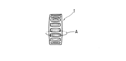
図12に示す試験機32を用いて,図13に示す保持器付きころを用いて保持器1の面当りを試験した結果を,図14の写真で示す。即ち,図12は,遠心荷重試験機の概略図を示している。試験機32は,ベース39に太陽輪33及び駆動モータ40が設置されている。駆動モータ40は,Vベルト41を介して回転体34が回転駆動する。試験機32は,コネクティングロッドの大端部を想定した構造に構成されている。試験機32は,太陽輪33の内周に回転体34が配設されており,回転体34の外周の等分した部分(図12では3等分)に太陽輪33の内周に沿って接触して回転する試験軸受部35が設けられている。試験軸受部35は,回転体34に回転せずに半径方向に移動自在に取り付けられた軸36に内輪37が取り付けられ,内輪37に保持器1を持つ保持器付きころを介して外輪38が取り付けられ,外輪38が太陽輪33の内周に沿って接触して回転するものになっている。この保持器付きころは,試験機32によって回転及び遠心力が負荷されるように構成されている。
FIG. 14 shows the result of testing the surface contact of the
この保持器付きころについて,保持器1の外周面9の面当りは,上記の試験機32を用いて行った試験結果及び計算結果から確認済みである。即ち,この保持器付きころの試験は,面当りを見ることを主眼にして実施され,回転数を5000rpm〜10000rpmに相当する1000rpm回転ごとに1時間ずつ変化させて観察した。図14は,図13に示す保持器1の軸方向でなる符号A領域の部分を拡大して示している。図14には,この保持器付きころの試験後の保持器1の一部を拡大した外観の状態が示されている。図14に示されるように,少し黒みかかった領域が点在して面当り部Hが示されているが,柱部4及び円環部3に渡って軸方向に沿って一様な状況になっている。保持器付きころにおける保持器1の面当りがなめらかになることによって,焼付きが防止され,エンジンのより高速回転に適応できるものになっている。
About this roller with a cage, the surface contact of the outer
次に,図9に示す第3実施例では,内側保持爪7Aの形成に特徴を有している。図10には,保持器1を旋削加工するに当たっての保持器素材29のL加工,即ち,窓抜きの加工前の加工品が示されている。保持器素材29は,L加工では外径がDlであり,内周突起42が形成されている。次いで,L加工された保持器素材29は,ポケット5を形成するための窓抜き加工が行われる。次に,保持器素材29は,窓抜き加工された後に,内周突起42を潰して,即ち,保持器1の内周面11と面一にして内側保持爪7Aが形成されている。即ち,第3実施例の保持器1は,旋削加工によって柱部4に内周突起42を形成しておき,次いで,窓抜き加工をしてポケット5を形成し,その後に,図9に示すように,内周突起42を内周面11と面一になるように押し潰して内側保持爪7Aを形成し,保持器1は,外径D,幅B,凹曲面18の単一半径Rk,内周面11の直径dk,凹曲面18の底直径ds,及びピッチ円直径P.C.D.に形成される。
Next, the third embodiment shown in FIG. 9 is characterized by the formation of the
図11に示された保持器1に形成されている内側保持爪7Bは,図9に示された保持器1に形成されている内側保持爪7Aの加工とは異なっており,内周面11にカシメ溝43を形成することによってポケット5へと突出する突起を形成し,該突起を内側保持爪7Bに形成している。従って,保持器1の内周内径dからカシメ溝43の底直径dkにかしめることになる。また,保持器1には,カシメ溝43を形成するために両端部に余肉を要することになり,単一半径はRsになっており,図9に示す単一半径Rkよりも小さいものになっている。即ち,保持器1に形成された内周凹部12の凹曲面18の単一半径は,サイズ上ではRk>Rsの関係になっている。従って,凹曲面18の単一半径が大きい分,若干ではあるが,保持器1を更に軽量化することができる。また,図9に示す保持器1は,図11に示す保持器1に比較して,保持器1の内側保持爪7Aの内周内径dkが保持器1の内周面11の内周内径dよりも大きくなっており,図11に示す保持器1よりも肉厚を小さくして内側保持爪7Aを形成できるものになっている。図9の保持器1の内側保持爪7Aは,柱部4における内周凹部12の両側の角部13にそれぞれ位置し,保持器1の内周面11と面一になっている。その結果,図9に示す保持器1は,図11の保持器1よりも軽量化され,図11に示す保持器1に比較して重量が95.7%に小さくなり,軽量化されている。従って,図9に示す保持器1は,重量が小さくなったことによって,遠心力等で保持器1の外周面24に作用する接触面圧が小さくなり,焼付き難い構造に構成され,それによって,エンジンのより高速回転に適用できるものになっている。また,図11に示す保持器1については,内周凹部12の断面凹曲面18は,単一半径Rsに形成され,保持器1の外周面24の面当りがなめらかになっている。
The
次に,図15を参照して,この発明による保持器付きころの第4実施例を説明する。第4実施例の保持器付きころは,上記の第1実施例と第2実施例が転造加工によって作製されるのに対して,切削加工である旋削加工によって保持器1が形成されていることを特徴としている。第4実施例の保持器付きころは,図9又は図11に示す凹曲面18が縦断面で見て単一半径の曲面に形成されているのに対して,近似させた凹曲面18に形成したものであり,内周凹部12の凹曲面が縦断面で見て2つの単一半径Rtを直線Lで結んだ複合の凹曲面20に形成されたものである。第4実施例に示す保持器付きころは,保持器1に内側保持爪7Bが形成されており,また,第1〜第3実施例と同様に効果を期待できるものである。第4実施例に示す保持器付きころは,特に,凹曲面18の2つの単一半径Rtが,例えば,略6mmであり,直線長さが上記各実施例と同様にころ直径相当の長さに形成されていれば近似して効果が大きいものである。
Next, a fourth embodiment of the roller with cage according to the present invention will be described with reference to FIG. The roller with cage of the fourth embodiment has the
この発明による保持器付きころは,エンジン等の機械装置,特に,エンジンのコネクティングロッド大端部に組み込んで好ましいものである。 The roller with a cage according to the present invention is preferably incorporated in a mechanical device such as an engine, particularly in a large end portion of a connecting rod of the engine.
1 保持器
2 ころ
3 円環部
4 柱部
5 ポケット
6 外側保持爪
7,7A,7B 内側保持爪
9 外周面
10 ころ案内部
11 内周面
12 内周凹部
13 角部
14,28 転造加工品
18,20 凹曲面
19 曲面
21,42 内周突起
26 厚肉部
27 漸減肉部
43 カシメ溝
d1,ds 底直径
P.C.D. ピッチ円直径
L 直線
R,Rk,Rs 凹曲面の単一半径
R1,Rt 複合の凹曲面の単一半径
DESCRIPTION OF
Claims (1)
前記保持器は,外周面が軸方向に面一に形成され,前記コネクティングロッドの前記大端部の内周面と前記柱部の前記外周面との面当たりを前記軸方向に沿って一様にするために,前記保持器の内周面の前記軸方向の中央に形成された内周凹部は縦断面で見て単一半径の曲面に成る凹曲面の形状に形成され,且つ前記凹曲面の底直径が前記ころのピッチ円直径より大きく形成されて,前記柱部は両端の厚肉部と該厚肉部間の漸減肉部から形成され,前記保持器の前記内周面を前記凹曲面に形成することにより転造加工が可能に且つ軽量化が可能に構成され,
前記柱部には,前記厚肉部と前記厚肉部に隣接する前記漸減肉部の一部との前記柱部の円周方向両側面が前記ころを案内するころ案内部に形成され,前記柱部の軸方向中央の円周方向両側に前記ポケットの一部を拡幅する拡幅部が形成され,且つ前記ころの外側への脱落を防止する外側保持爪が前記厚肉部に形成され,前記外側保持爪の外周側は前記保持器の前記外周面と面一に形成されていることを特徴とする保持器付きころ。 An annular part at both ends extending in parallel to the circumferential direction and spaced apart in the axial direction, and the annular part extending in a circumferential direction between the annular parts and a column part having an integral structure. A roller with a cage applied to a large end portion of a connecting rod of an engine comprising a cage and rollers respectively accommodated in pockets formed between the pillars;
The retainer has an outer circumferential surface that is flush with the axial direction, and the contact between the inner circumferential surface of the large end portion of the connecting rod and the outer circumferential surface of the column portion is uniform along the axial direction. In order to achieve this, the inner peripheral recess formed in the axial center of the inner peripheral surface of the cage is formed in the shape of a concave curved surface that is a curved surface having a single radius when viewed in a longitudinal section , and the concave curved surface A bottom diameter of the roller is larger than a pitch circle diameter of the roller, and the column part is formed of a thick part at both ends and a gradually reduced thickness part between the thick parts, and the inner peripheral surface of the cage is recessed in the concave part. By forming it on a curved surface, it can be rolled and made lightweight.
In the column part, both circumferential side surfaces of the column part of the thick part and a part of the gradually decreasing thickness part adjacent to the thick part are formed in a roller guide part for guiding the roller, widened portion formed for widening a portion of the pocket on both sides in the circumferential direction of the axial center of the pillar portion, the outer holding claw for preventing detachment of the outer且previous SL rollers is formed in the thick portion A roller with a cage, wherein an outer peripheral side of the outer holding claw is formed flush with the outer peripheral surface of the cage.
Priority Applications (3)
| Application Number | Priority Date | Filing Date | Title |
|---|---|---|---|
| JP2004246396A JP4464767B2 (en) | 2004-02-23 | 2004-08-26 | Roller with cage |
| TW94103506A TWI251057B (en) | 2004-08-26 | 2005-02-04 | Roller bearing cage and method of producing the same |
| US11/055,632 US7252436B2 (en) | 2004-02-23 | 2005-02-11 | Roller bearing cage and method of producing the same |
Applications Claiming Priority (2)
| Application Number | Priority Date | Filing Date | Title |
|---|---|---|---|
| JP2004045814 | 2004-02-23 | ||
| JP2004246396A JP4464767B2 (en) | 2004-02-23 | 2004-08-26 | Roller with cage |
Publications (3)
| Publication Number | Publication Date |
|---|---|
| JP2005273897A JP2005273897A (en) | 2005-10-06 |
| JP2005273897A5 JP2005273897A5 (en) | 2006-07-20 |
| JP4464767B2 true JP4464767B2 (en) | 2010-05-19 |
Family
ID=34863510
Family Applications (1)
| Application Number | Title | Priority Date | Filing Date |
|---|---|---|---|
| JP2004246396A Active JP4464767B2 (en) | 2004-02-23 | 2004-08-26 | Roller with cage |
Country Status (2)
| Country | Link |
|---|---|
| US (1) | US7252436B2 (en) |
| JP (1) | JP4464767B2 (en) |
Families Citing this family (9)
| Publication number | Priority date | Publication date | Assignee | Title |
|---|---|---|---|---|
| JP3984972B2 (en) * | 2004-05-13 | 2007-10-03 | 日本トムソン株式会社 | Roller bearing and method for manufacturing the same |
| US7611289B2 (en) * | 2004-09-24 | 2009-11-03 | Ntn Corporation | Rollers with retainer |
| JP2007010026A (en) * | 2005-06-30 | 2007-01-18 | Ntn Corp | Cylindrical roller bearing and its cage |
| DE102007048655A1 (en) * | 2007-10-10 | 2008-02-07 | Schaeffler Kg | Cage segment of plastic cage for anti-friction bearing, particularly for large anti-friction bearing, are arranged at front side in engaging way and on each other in impinging way in peripheral direction |
| JP5189427B2 (en) * | 2008-07-17 | 2013-04-24 | Ntn株式会社 | Roller bearing cage and rolling bearing |
| JP5703940B2 (en) * | 2011-04-28 | 2015-04-22 | トヨタ紡織株式会社 | Processing method and processing apparatus for rolling bearing |
| DE102012101651A1 (en) * | 2012-02-29 | 2013-08-29 | Thyssenkrupp Rothe Erde Gmbh | Method for producing a roller bearing cage for an axial-radial roller bearing and axial-radial roller bearing |
| USD809033S1 (en) * | 2015-12-28 | 2018-01-30 | Ntn Corporation | Retainer for rolling bearing |
| CN116586925B (en) * | 2023-07-19 | 2023-09-19 | 山东金帝精密机械科技股份有限公司 | Large-scale bearing retainer production method, equipment and medium based on images |
Family Cites Families (6)
| Publication number | Priority date | Publication date | Assignee | Title |
|---|---|---|---|---|
| US5540506A (en) * | 1993-02-25 | 1996-07-30 | Nippon Thompson Co., Ltd. | Roller and cage assembly |
| JP3668274B2 (en) | 1995-02-08 | 2005-07-06 | 日本トムソン株式会社 | Roller with cage |
| JP3735160B2 (en) | 1995-12-28 | 2006-01-18 | Ntn株式会社 | Needle roller bearing cage and method of manufacturing the same |
| JPH09242763A (en) | 1996-03-12 | 1997-09-16 | Nippon Seiko Kk | Manufacture of rolling bearing |
| DE29720767U1 (en) * | 1997-11-22 | 1998-01-15 | Skf Gmbh | Solid cage for roller bearings |
| JP4527912B2 (en) * | 2001-09-19 | 2010-08-18 | 日本トムソン株式会社 | Roller with cage |
-
2004
- 2004-08-26 JP JP2004246396A patent/JP4464767B2/en active Active
-
2005
- 2005-02-11 US US11/055,632 patent/US7252436B2/en active Active
Also Published As
| Publication number | Publication date |
|---|---|
| US7252436B2 (en) | 2007-08-07 |
| JP2005273897A (en) | 2005-10-06 |
| US20050185874A1 (en) | 2005-08-25 |
Similar Documents
| Publication | Publication Date | Title |
|---|---|---|
| JP3668274B2 (en) | Roller with cage | |
| US8944696B2 (en) | Cage for radial roller bearing | |
| US7252436B2 (en) | Roller bearing cage and method of producing the same | |
| JP4527912B2 (en) | Roller with cage | |
| JP2008057762A (en) | Ball bearing | |
| JP2006226318A (en) | One-way clutch built-in pulley device | |
| JP2528882Y2 (en) | Roller bearings for engines | |
| WO2006075658A1 (en) | Cam follower device | |
| JP2009014078A (en) | Needle roller bearing and crankshaft supporting structure | |
| JP3984972B2 (en) | Roller bearing and method for manufacturing the same | |
| JP5064910B2 (en) | Needle roller bearing and crankshaft support structure | |
| JP2006242199A (en) | Thrust roller bearing | |
| JP2007071344A (en) | Outboard motor engine and crank shaft support structure for outboard motor engine | |
| JP2008232221A (en) | Thrust needle roller bearing | |
| US20050064977A1 (en) | Roller/retainer assembly for planetary gear and planetary gears support using the same | |
| JP4627751B2 (en) | Outer ring member manufacturing apparatus and outer ring member manufacturing method | |
| JP2009085277A (en) | Sealing device for rolling bearing and grease-lubricated rolling bearing | |
| JP2004190778A (en) | Thrust needle roller bearing | |
| EP3693626B1 (en) | Retainer for rolling bearing | |
| JP2007064304A (en) | Crankshaft support structure of engine and two- cycle engine | |
| JP2009168180A5 (en) | ||
| JP2004301232A (en) | Retainer for cylindrical roller bearing | |
| JP2007263211A (en) | Resin-made crown shaped cage for ball bearing | |
| JP2004011667A (en) | Roller bearing and cage for the same | |
| JP4563885B2 (en) | Needle roller bearing |
Legal Events
| Date | Code | Title | Description |
|---|---|---|---|
| A521 | Written amendment |
Free format text: JAPANESE INTERMEDIATE CODE: A523 Effective date: 20060607 |
|
| A621 | Written request for application examination |
Free format text: JAPANESE INTERMEDIATE CODE: A621 Effective date: 20060607 |
|
| A977 | Report on retrieval |
Free format text: JAPANESE INTERMEDIATE CODE: A971007 Effective date: 20080902 |
|
| A131 | Notification of reasons for refusal |
Free format text: JAPANESE INTERMEDIATE CODE: A131 Effective date: 20090602 |
|
| A521 | Written amendment |
Free format text: JAPANESE INTERMEDIATE CODE: A523 Effective date: 20090723 |
|
| A131 | Notification of reasons for refusal |
Free format text: JAPANESE INTERMEDIATE CODE: A131 Effective date: 20091124 |
|
| A521 | Written amendment |
Free format text: JAPANESE INTERMEDIATE CODE: A523 Effective date: 20091225 |
|
| TRDD | Decision of grant or rejection written | ||
| A01 | Written decision to grant a patent or to grant a registration (utility model) |
Free format text: JAPANESE INTERMEDIATE CODE: A01 Effective date: 20100216 |
|
| A01 | Written decision to grant a patent or to grant a registration (utility model) |
Free format text: JAPANESE INTERMEDIATE CODE: A01 |
|
| A61 | First payment of annual fees (during grant procedure) |
Free format text: JAPANESE INTERMEDIATE CODE: A61 Effective date: 20100219 |
|
| FPAY | Renewal fee payment (event date is renewal date of database) |
Free format text: PAYMENT UNTIL: 20130226 Year of fee payment: 3 |
|
| R150 | Certificate of patent or registration of utility model |
Ref document number: 4464767 Country of ref document: JP Free format text: JAPANESE INTERMEDIATE CODE: R150 Free format text: JAPANESE INTERMEDIATE CODE: R150 |
|
| FPAY | Renewal fee payment (event date is renewal date of database) |
Free format text: PAYMENT UNTIL: 20160226 Year of fee payment: 6 |
|
| R250 | Receipt of annual fees |
Free format text: JAPANESE INTERMEDIATE CODE: R250 |
|
| R250 | Receipt of annual fees |
Free format text: JAPANESE INTERMEDIATE CODE: R250 |
|
| R250 | Receipt of annual fees |
Free format text: JAPANESE INTERMEDIATE CODE: R250 |