JP2006183997A6 - Air conditioner - Google Patents

Air conditioner Download PDF

Info

Publication number
JP2006183997A6
JP2006183997A6 JP2005357080A JP2005357080A JP2006183997A6 JP 2006183997 A6 JP2006183997 A6 JP 2006183997A6 JP 2005357080 A JP2005357080 A JP 2005357080A JP 2005357080 A JP2005357080 A JP 2005357080A JP 2006183997 A6 JP2006183997 A6 JP 2006183997A6
Authority
JP
Japan
Prior art keywords
opening
intake
suction
exhaust
dust
Prior art date
Legal status (The legal status is an assumption and is not a legal conclusion. Google has not performed a legal analysis and makes no representation as to the accuracy of the status listed.)
Granted
Application number
JP2005357080A
Other languages
Japanese (ja)
Other versions
JP2006183997A (en
JP3992722B2 (en
Inventor
善樹 泉
孝 杉尾
努 清水
Current Assignee (The listed assignees may be inaccurate. Google has not performed a legal analysis and makes no representation or warranty as to the accuracy of the list.)
Panasonic Corp
Panasonic Holdings Corp
Original Assignee
Panasonic Corp
Matsushita Electric Industrial Co Ltd
Priority date (The priority date is an assumption and is not a legal conclusion. Google has not performed a legal analysis and makes no representation as to the accuracy of the date listed.)
Filing date
Publication date
Application filed by Panasonic Corp, Matsushita Electric Industrial Co Ltd filed Critical Panasonic Corp
Priority to JP2005357080A priority Critical patent/JP3992722B2/en
Priority claimed from JP2005357080A external-priority patent/JP3992722B2/en
Publication of JP2006183997A publication Critical patent/JP2006183997A/en
Publication of JP2006183997A6 publication Critical patent/JP2006183997A6/en
Application granted granted Critical
Publication of JP3992722B2 publication Critical patent/JP3992722B2/en
Expired - Fee Related legal-status Critical Current
Anticipated expiration legal-status Critical

Links

Images

Abstract


【課題】エアフィルタを空気調和機の室内機から取り外し、水洗いもしくは掃除機などで付着した塵埃を掃除するというメンテナンスを要した。
【解決手段】本発明は室内機1に付着した塵埃を吸込む吸込み孔を有する吸込みノズル16と、吸込みノズル16に接続された吸排気装置30とを少なくとも有するフィルター清掃装置を備え、フィルター清掃装置に一端に接続され、他端が室外に連通された排気ダクト17とを備えた空気調和機であって、前記吸排気装置30によってフィルター清掃装置に吸込まれた塵埃と室内側空気のいずれか一方または双方を排出する。
【選択図】図4

[PROBLEMS] To remove an air filter from an indoor unit of an air conditioner and to clean the dust adhered by washing with water or a vacuum cleaner.
The present invention includes a filter cleaning device having at least a suction nozzle 16 having a suction hole for sucking dust adhering to the indoor unit 1 and an intake / exhaust device 30 connected to the suction nozzle 16, and the filter cleaning device includes: An air conditioner including an exhaust duct 17 connected to one end and communicated to the outside at the other end, wherein either one of dust and indoor air sucked into the filter cleaning device by the intake / exhaust device 30 or Eject both.
[Selection] Figure 4

Description

本発明は、エアフィルタを自動清掃可能な空気調和機に関するものである。     The present invention relates to an air conditioner capable of automatically cleaning an air filter.

送風ファンにより吸い込んだ空気を熱交換器で冷却もしくは加熱した後、室内へ送風する空気調和機には、空気中に漂う塵埃が室内機内部へ侵入することを防止するために、吸い込み部の裏側にエアフィルタが設けられている。このエアフィルタに塵埃が付着して堆積すると、通気抵抗が増大して空気調和機の室内機のCOP(成績係数=(冷房能力/所要動力))が低下し、消費電力が増大するため、一般にエアフィルタは、付着した塵埃を清掃できるように着脱自在に構成されている。   The air conditioner that blows air into the room after the air drawn in by the blower fan is cooled or heated by a heat exchanger is installed on the back side of the suction unit to prevent dust floating in the air from entering the indoor unit. Is provided with an air filter. If dust adheres to and accumulates on this air filter, the airflow resistance increases and the COP (coefficient of performance = (cooling capacity / required power)) of the indoor unit of the air conditioner decreases and power consumption increases. The air filter is configured to be detachable so that attached dust can be cleaned.

しかし、このようにエアフィルタを着脱自在に構成した空気調和機では、空気調和機の使用頻度に応じて、比較的短期間の周期で、エアフィルタを空気調和機の室内機から取り外し、水洗いもしくは掃除機などで付着した塵埃を掃除するというメンテナンスを要し、多くの手間や時間がかかってしまう問題があった。   However, in an air conditioner having an air filter detachably configured in this manner, the air filter is removed from the air conditioner indoor unit in a relatively short period according to the frequency of use of the air conditioner and washed with water or There is a problem that it takes a lot of trouble and time because it requires maintenance to clean the dust adhering with a vacuum cleaner.

この問題に対処すべく、図13、図14に示すようなエアフィルタ装置50が特開2001−99479号公報に提案されている。
このエアフィルタ装置50では、帯状のエアフィルタ51を、室内機の上部と下部とにそれぞれ配置した繰り出し/巻き取り用の軸52、53との間に渡って、吸い込み部57、58に裏面から臨むように掛け渡し、一方の軸53をモータ54などにより回転駆動させることでエアフィルタ51を上下に移動自在に構成している。そして、このエアフィルタ51の配置箇所下端部の近傍に、エアフィルタ51に付着した塵埃を掃除する清掃用ブラシ55を設けるとともに、この清掃用ブラシ55の下方に、清掃用ブラシ55により掻き落とされた塵埃を回収するダストボックス56を配設している。
In order to cope with this problem, an air filter device 50 as shown in FIGS. 13 and 14 is proposed in Japanese Patent Laid-Open No. 2001-99479.
In this air filter device 50, the belt-like air filter 51 is placed between the feeding / rewinding shafts 52, 53 arranged at the upper part and the lower part of the indoor unit, respectively, to the suction parts 57, 58 from the back surface. The air filter 51 is configured so as to be movable up and down by spanning it so as to face and rotating one shaft 53 by a motor 54 or the like. A cleaning brush 55 for cleaning dust adhering to the air filter 51 is provided in the vicinity of the lower end of the location where the air filter 51 is disposed, and the cleaning brush 55 is scraped off below the cleaning brush 55. A dust box 56 for collecting collected dust is provided.

このエアフィルタ装置50を備えた空気調和機によれば、所定操作を行ってエアフィルタ駆動用のモータ54を駆動させることで、塵埃が付着したエアフィルタ51が巻き取りられるとともにエアフィルタ51の清掃動作が行われるため、エアフィルタ51を取り外して水洗いするなどの手間を省くことができる。
特開2001−99479号公報
According to the air conditioner provided with the air filter device 50, the air filter 51 is wound up and the air filter 51 is cleaned by performing a predetermined operation to drive the motor 54 for driving the air filter. Since the operation is performed, the trouble of removing the air filter 51 and washing it with water can be saved.
JP 2001-99479 A

しかしながら、前記特許文献1に開示されたエアフィルタ装置50を備えた空気調和機によれば、エアフィルタ51の清掃動作は自動的に行わせて手間を省けるものの、ダストボックス56に回収された塵埃については人が清掃しなければならず、このダストボックス56の清掃作業という定期的なメンテナンスを必要とし、このメンテナンスのための手間や時間がかかってしまう課題がある。   However, according to the air conditioner equipped with the air filter device 50 disclosed in Patent Document 1, although the cleaning operation of the air filter 51 is automatically performed and labor can be saved, the dust collected in the dust box 56 is reduced. There is a problem that a person has to clean and requires regular maintenance of the dust box 56, which takes time and labor for the maintenance.

上記課題を解決するために本発明は、室内機に付着した塵埃を吸込む吸込み孔を有する吸込みノズルと、前記吸込みノズルに接続された吸排気装置とを少なくとも有するフィルター清掃装置を備え、前記フィルター清掃装置に一端に接続され、他端が室外に連通された排気ダクトとを備えた空気調和機であって、前記吸排気装置によって前記フィルター清掃装置に吸込まれた塵埃と室内側空気のいずれか一方または双方を排出することを特徴とする。   In order to solve the above problems, the present invention comprises a filter cleaning device having at least a suction nozzle having a suction hole for sucking dust adhering to an indoor unit, and an intake / exhaust device connected to the suction nozzle. An air conditioner having an exhaust duct connected to one end of the apparatus and having the other end communicating with the outside of the apparatus, wherein either the dust sucked into the filter cleaning device by the intake / exhaust device or indoor air Or, both are discharged.

上記構成によれば、1つの吸排気装置により吸塵運転と換気運転とを兼用して行うことができるので、それぞれ吸塵用の吸排気装置と換気用の吸排気装置とを別個に設けた場合に比べて、収容スペースを抑えることができるとともに、製造コストも低減させることができる。   According to the above configuration, since the dust suction operation and the ventilation operation can be performed by one intake / exhaust device, when the dust intake / exhaust device and the ventilation intake / exhaust device are provided separately, respectively. In comparison, the storage space can be reduced, and the manufacturing cost can be reduced.

さらに、上記構成によれば、室内ユニット中に設けるファンが単一で塵埃と換気が可能となる。従って、室内ユニット内におけるファンの占有スペースを小さくすることができ、室内ユニットの筐体をコンパクト化することができる。   Further, according to the above configuration, a single fan provided in the indoor unit can be used for dust and ventilation. Therefore, the space occupied by the fan in the indoor unit can be reduced, and the housing of the indoor unit can be made compact.

また、本発明は、フィルター清掃装置に換気用開口部及び前記換気用開口部を開閉する開閉体を設け、前記換気用開口部及び前記換気用開口部を開閉する開閉体の開時に室内の空気と吸排気装置を連通することを特徴とする。
また、本発明は、換気用開口部及び前記換気用開口部を開閉する開閉体が吸込みノズルと吸排気装置の間に設けられたことを特徴とする。
Further, the present invention provides a filter cleaning device provided with a ventilation opening and an opening / closing body for opening and closing the ventilation opening, and the indoor air when the opening for opening and closing the ventilation opening and the opening for ventilation is opened. And an intake / exhaust device in communication with each other.
Further, the present invention is characterized in that a ventilation opening and an opening / closing body for opening and closing the ventilation opening are provided between the suction nozzle and the intake / exhaust device.

また、本発明は、換気用開口部及び前記換気用開口部を開閉する開閉体が吸排気装置に設けられたことを特徴とする。
また、本発明は、換気用開口部及び前記換気用開口部を開閉する開閉体が吸込みノズルに設けられたことを特徴とする。
また、本発明は、換気用開口部及び前記換気用開口部を開閉する開閉体が開口部を有し、前記開口部は室内側空気を通過させることを特徴とする。
Further, the present invention is characterized in that the ventilation opening and the opening / closing body for opening and closing the ventilation opening are provided in the intake / exhaust device.
Further, the present invention is characterized in that the suction nozzle is provided with a ventilation opening and an opening / closing body for opening and closing the ventilation opening.
Further, the present invention is characterized in that the opening for ventilation and the opening / closing body for opening and closing the opening for ventilation have an opening, and the opening allows the indoor air to pass therethrough.

また、本発明は、吸排気装置は少なくとも、塵埃を吸込む排塵ファンと、塵埃と前記フィルター清掃装置に吸い込まれた室内側空気のいずれか一方または双方を排出する給排気ファンとを有することを特徴とする。   Further, according to the present invention, the intake / exhaust device includes at least a dust exhaust fan that sucks dust, and a supply / exhaust fan that discharges one or both of dust and indoor air sucked into the filter cleaning device. Features.

また、本発明は、吸排気装置は単一の給排気ファンを備えたことを特徴とする。   According to the present invention, the intake / exhaust device includes a single supply / exhaust fan.

本発明によれば、室内ユニット中に設けるファンが単一で塵埃と換気が可能となる。従って、室内ユニット内におけるファンの占有スペースを小さくすることができ、室内ユニットの筐体をコンパクト化することができる。   According to the present invention, a single fan provided in the indoor unit can be used for dust and ventilation. Therefore, the space occupied by the fan in the indoor unit can be reduced, and the housing of the indoor unit can be made compact.

以下、本発明の実施の形態について、図面を参照しながら説明する。
(実施の形態1)
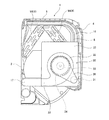
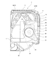
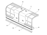
図1〜図3に示すように、この空気調和機における室内機1は、両側面部や底面部をなす台枠2と、室内機1の前面部および上面部箇所に設けられ、網目状のフィルタ部8aがフィルタ枠8bに多数はめ込まれてなるエアフィルタ8と、このエアフィルタ8の前方ならびに上方に開閉自在に取り付けられた外面パネル4などで、主な外殻部分が構成されている。外面パネル4の上面部と前面部とにはそれぞれ室内空気を吸い込む吸い込み部5、6が形成され、下部前方に吹き出し部7が形成されている。室内機1内における吸い込み部5、6と吹き出し部7とを結ぶ空気通路には、前記エアフィルタ8と2個の熱交換器9A、9Bからなる熱交換器9とクロスフローファンからなる送風ファン10とが配置されている。そして、送風ファン10によって吸い込み部5、6から吸込まれた空気は、エアフィルタ8を通り、熱交換器9で冷却もしくは加熱された後、吹き出し部7から吹き出される。なお、吹き出し部7を囲むように、一方の熱交換器9Aが送風ファン10の上方から前方にわたって配置され、他方の熱交換器9Bが送風ファン10の上方から後方にわたって配置されている。送風ファン10による空気の送り出しをスムーズにするために、室内機1の背面近傍にリアガイダ11が設けられているとともに、スタビライザ12が水受け皿13の端部に設けられている。なお、14は風向き変更羽根である。
Hereinafter, embodiments of the present invention will be described with reference to the drawings.
(Embodiment 1)
As shown in FIGS. 1 to 3, the indoor unit 1 in this air conditioner is provided with a frame 2 that forms both side surfaces and a bottom surface portion, and a front and top surface portion of the indoor unit 1. A main outer shell portion is composed of an air filter 8 in which a large number of portions 8a are fitted in a filter frame 8b, an outer surface panel 4 attached to the front and upper sides of the air filter 8 so as to be openable and closable. The upper surface portion and the front surface portion of the outer panel 4 are respectively formed with suction portions 5 and 6 for sucking room air, and a blowing portion 7 is formed in front of the lower portion. In the air passage connecting the suction parts 5 and 6 and the blowing part 7 in the indoor unit 1, a blower fan comprising the air filter 8, the heat exchanger 9 comprising two heat exchangers 9 </ b> A and 9 </ b> B, and a cross flow fan. 10 are arranged. The air sucked from the suction parts 5 and 6 by the blower fan 10 passes through the air filter 8 and is cooled or heated by the heat exchanger 9 and then blown out from the blowing part 7. Note that one heat exchanger 9 </ b> A is arranged from the upper side to the front side of the blower fan 10 and the other heat exchanger 9 </ b> B is arranged from the upper side to the rear side of the blower fan 10 so as to surround the blowing part 7. A rear guider 11 is provided in the vicinity of the rear surface of the indoor unit 1 and a stabilizer 12 is provided at an end of the water tray 13 in order to smoothly send out air by the blower fan 10. Reference numeral 14 denotes a wind direction changing blade.

図4にも示すように、室内機1内の側面近傍には、エアフィルタ8に付着した塵埃を吸引して排出するための吸排気装置30が設置されている。この吸排気装置30の吸い込み側部分(吸い込みダクト接続口31)には、蛇腹形状の吸い込みダクト15を介して吸い込みノズル16が接続されているとともに、吸排気装置30の吹き出し側部分(排気ダクト接続口32)には、その先端が室外へ連通されている排気ダクト17が接続されている。   As shown in FIG. 4, an intake / exhaust device 30 for sucking and discharging dust adhering to the air filter 8 is installed near the side surface in the indoor unit 1. A suction nozzle 16 is connected to a suction side portion (suction duct connection port 31) of the intake / exhaust device 30 via a bellows-shaped suction duct 15 and a blow-out side portion (exhaust duct connection) of the intake / exhaust device 30. An exhaust duct 17 whose tip communicates with the outside is connected to the port 32).

吸い込みノズル16は、エアフィルタ8の風上側の面に臨むように奥行方向ならびに上下方向に延設された形状に形成されているとともに、その奥端部や下端部が、エアフィルタ8のフィルタ枠8bにおける上部奥端部や下端部に形成されたガイド溝8c、8dに挿入され、エアフィルタ8の風上側面に沿う姿勢で左右に移動自在に案内されている。また、吸い込みノズル16の下部は、左右に延びるように配置されたねじ軸18に螺合されており、伝達ギヤ19、20を介してねじ軸18をノズル駆動用モータ21により駆動することで、吸い込みノズル16が左右に移動される。   The suction nozzle 16 is formed in a shape extending in the depth direction and the vertical direction so as to face the windward surface of the air filter 8, and the back end portion and the lower end portion thereof are formed in the filter frame of the air filter 8. 8b is inserted into guide grooves 8c and 8d formed at the upper back end and the lower end of the air filter 8b, and is guided so as to move left and right in a posture along the windward side surface of the air filter 8. The lower portion of the suction nozzle 16 is screwed to a screw shaft 18 arranged so as to extend left and right, and the screw shaft 18 is driven by a nozzle drive motor 21 via transmission gears 19 and 20. The suction nozzle 16 is moved left and right.

吸い込みノズル16におけるエアフィルタ8に臨む面には、エアフィルタ8の上面部から前面部にかけて複数の吸い込み孔16aが並んで形成され、後述する吸排気装置30の吸引動作により、各吸い込み孔16aからエアフィルタ8の塵埃を吸い込み可能に構成されている。   A plurality of suction holes 16a are formed on the surface of the suction nozzle 16 facing the air filter 8 from the upper surface portion to the front surface portion of the air filter 8, and each suction hole 16a is formed by suction operation of the intake / exhaust device 30 described later. The air filter 8 is configured to be able to suck dust.

吸い込みノズル16と吸排気装置30の吸い込みダクト接続口31とをつなぐ吸い込みダクト15は、一部が屈曲することで、エアフィルタ8の左右方向の位置にかかわらず、吸排気装置30への吸入用流路を良好に形成するようになっている。   The suction duct 15 that connects the suction nozzle 16 and the suction duct connection port 31 of the suction / exhaust device 30 is partially bent so that the suction duct 15 can be sucked into the intake / exhaust device 30 regardless of the position of the air filter 8 in the left-right direction. The flow path is formed well.

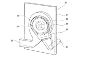
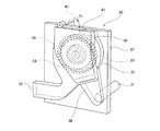
図5〜図7に示すように、吸排気装置30は、吸排気モータ33により回転される遠心式の吸排気ファン34と、この吸排気ファン34を収容するケーシング35と、このケーシング35の風上側にケーシング35と一体的に設けられた吸引カバー36と、ケーシング35などが取り付けられている取付基板37とを有する。そして、図1などに示すように、吸排気装置30(吸排気装置30のケーシング35および吸引カバー36)が、室内機1内部の側面部において、上下方向ならびに奥行方向には延設されている一方、左右方向にはその厚みが小さい扁平形状に形成されて配置されている。また、図5〜図7に示すように、吸引カバー36は、吸い込みダクト15に接続された吸い込みダクト接続口31と吸排気ファン34への吸い込み口38との両者が片面側に開口して臨むように形成され、側面視して、吸い込みダクト接続口31の外周部分31aと吸排気ファン34への吸い込み口38の外周部分38aとをなだらかにつないだ流路形状(例えば、各種エンジンのピストンを接続するクランク軸を側方から見たようなクランク形状)に形成されている。なお、この第1の実施の形態では、吸い込みダクト接続口31の外周部分31aと吸排気ファン34への吸い込み口38の外周部分38aとを直線的になだらかにつないでいる場合を示したが、これに限るものではなく、曲線によりなだらかにつないでもよい。また、この第1の実施の形態では、吸引カバー36において、吸い込みダクト接続口31から吸排気ファン34への吸い込み口38への流路が斜め上方に延びるように配置され、また、ケーシング35の下部に設けられた排気口がそのまま方向に延ばされて排気ダクト接続口32を形成している。   As shown in FIGS. 5 to 7, the intake / exhaust device 30 includes a centrifugal intake / exhaust fan 34 that is rotated by an intake / exhaust motor 33, a casing 35 that accommodates the intake / exhaust fan 34, and a wind of the casing 35. A suction cover 36 provided integrally with the casing 35 and an attachment substrate 37 to which the casing 35 and the like are attached are provided on the upper side. And as shown in FIG. 1 etc., the intake / exhaust device 30 (the casing 35 and the suction cover 36 of the intake / exhaust device 30) is extended in the up-down direction and the depth direction in the side part inside the indoor unit 1. On the other hand, in the left-right direction, a flat shape with a small thickness is arranged. As shown in FIGS. 5 to 7, the suction cover 36 faces both the suction duct connection port 31 connected to the suction duct 15 and the suction port 38 to the intake / exhaust fan 34 so as to open on one side. As seen from the side, the shape of the flow path gently connecting the outer peripheral portion 31a of the suction duct connection port 31 and the outer peripheral portion 38a of the suction port 38 to the intake / exhaust fan 34 (for example, pistons of various engines) The crankshaft to be connected is formed in a crank shape as viewed from the side). In the first embodiment, the outer peripheral portion 31a of the suction duct connection port 31 and the outer peripheral portion 38a of the suction port 38 to the intake / exhaust fan 34 are connected smoothly and linearly. It is not limited to this, and it may be connected gently by a curve. In the first embodiment, the suction cover 36 is disposed so that the flow path from the suction duct connection port 31 to the suction port 38 to the suction / exhaust fan 34 extends obliquely upward. The exhaust port provided in the lower part is extended in the direction as it is to form the exhaust duct connection port 32.

この構成において、エアフィルタ8の清掃を行う際には、所定の操作を行うなどして(例えば、清掃用ボタンを押すなどして)、吸排気モータ33およびノズル駆動用モータ21を駆動させる。すると、吸排気装置30が作動した状態で、吸い込みノズル16がエアフィルタ8の風上側の面に沿って移動し、この際、エアフィルタ8に付着した塵埃が空気とともに吸い込み孔16aを通して吸い込みノズル16内に吸い込まれ、吸い込みダクト15から吸排気装置30に吸引された塵埃が空気とともに排気ダクト17を通して室外に排出される。これにより、エアフィルタ8の塵埃を自動で室外に排出でき、塵埃の清掃作業を人が行わなくて済んでメンテナンスフリーを実現できる。   In this configuration, when the air filter 8 is cleaned, the intake / exhaust motor 33 and the nozzle driving motor 21 are driven by performing a predetermined operation (for example, pressing a cleaning button). Then, the suction nozzle 16 moves along the windward surface of the air filter 8 in a state in which the intake / exhaust device 30 is activated. At this time, dust adhering to the air filter 8 together with air passes through the suction hole 16a and the suction nozzle 16 The dust sucked in and sucked into the suction / exhaust device 30 from the suction duct 15 is discharged out of the room together with air through the exhaust duct 17. Thereby, the dust of the air filter 8 can be automatically discharged to the outside, and the maintenance work can be realized without the need for a person to perform dust cleaning work.

また、上記構成によれば、吸排気装置30として、中央部から吸い込んで遠心力を利用しながら外周部から排気する遠心式の吸排気ファン34を用いることで、低騒音とすることができる。さらに、ケーシング35の風上側に一体的に吸引カバー36を設け、この吸引カバー36を、吸い込みダクト接続口31と吸排気ファンへ34の吸い込み口38とが片面に開口して臨むように形成させ、側面視して、吸い込みダクト接続口31の外周部分と前記吸い込み口38の外周部分とをなだらかにつないだ流路形状に形成させたことで、吸い込みダクト15からの塵埃を含んだ空気が吸引カバー36内を良好な流速で、かつエアフィルタ8から吸った塵埃が吸引カバー36の一部で滞留することなく、ケーシング35内に吸い込まれて、良好に室外に排出される。   Moreover, according to the said structure, it can be set as low noise by using the centrifugal intake / exhaust fan 34 which sucks in from the center part and exhausts from an outer peripheral part using the centrifugal force as the intake / exhaust apparatus 30. FIG. Further, a suction cover 36 is integrally provided on the windward side of the casing 35, and the suction cover 36 is formed so that the suction duct connection port 31 and the suction port 38 of the intake / exhaust fan 34 are opened and faced on one side. The air containing dust from the suction duct 15 is sucked by forming a flow path shape in which the outer peripheral portion of the suction duct connection port 31 and the outer peripheral portion of the suction port 38 are gently connected in a side view. The dust sucked from the air filter 8 at a good flow rate in the cover 36 is sucked into the casing 35 without staying in a part of the suction cover 36 and is well discharged outside the room.

また、ケーシング35および吸引カバー36を、左右方向の厚みが小さい扁平形状に形成したり、吸排気モータ33を吸排気ファン34に内蔵させて配置したりすることで、吸排気装置30を、室内機1の側面部にコンパクトに収容できるとともに、熱交換を行う流路に突出して支障をきたすようなことがなく、室内機1が大型化することを最小限に抑えることができる。   Further, by forming the casing 35 and the suction cover 36 in a flat shape with a small thickness in the left-right direction, or by arranging the intake / exhaust motor 33 in the intake / exhaust fan 34, the intake / exhaust device 30 can be placed indoors. While being compactly accommodated in the side part of the machine 1, it does not project into the flow path for heat exchange and cause trouble, and the increase in the size of the indoor unit 1 can be minimized.

さらに、高風量・低騒音型のファンとして知られているシロッコファンを吸排気ファン34として用いることによっても、吸排気装置30を小型化することができるとともに、高速回転させても低騒音となるので、室内機1として適している。   Further, by using a sirocco fan, which is known as a high air volume / low noise type fan, as the intake / exhaust fan 34, the intake / exhaust device 30 can be reduced in size, and low noise can be achieved even if it is rotated at a high speed. Therefore, it is suitable as the indoor unit 1.

また、吸い込みノズル16をエアフィルタ8に沿って横方向に移動自在に構成することにより、エアフィルタ8が側面視して湾曲部を有したり、異形部を有したりする場合でも、エアフィルタ8の塵埃を良好に吸い込むことができる。
(実施の形態2)
次に、本発明の実施の形態2を、図8〜図10を用いて説明する。
Further, by configuring the suction nozzle 16 to be movable in the lateral direction along the air filter 8, even when the air filter 8 has a curved portion or a deformed portion in side view, the air filter 8 dust can be sucked in well.
(Embodiment 2)
Next, a second embodiment of the present invention will be described with reference to FIGS.

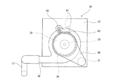
図8〜図10に示すように、この空気調和機における室内機1は、以下の点で上記実施の形態1の室内機1と相違している。すなわち、この空気調和機における室内機1では、吸排気装置30の吸引カバー36の一部、ここでは上部に換気用開口部40が形成されているとともに、この換気用開口部40を開閉する開閉体41が設けられている。開閉体41は、開閉用モータなどを備えた開閉用駆動手段42により回動される。   As shown in FIGS. 8 to 10, the indoor unit 1 in this air conditioner is different from the indoor unit 1 of the first embodiment in the following points. That is, in the indoor unit 1 in this air conditioner, a ventilation opening 40 is formed in a part of the suction cover 36 of the intake / exhaust device 30, here the upper part, and the opening / closing for opening and closing the ventilation opening 40. A body 41 is provided. The opening / closing body 41 is rotated by an opening / closing drive means 42 having an opening / closing motor or the like.

なお、この実施の形態2では、開閉体41が略水平となって換気用開口部40を閉鎖する閉鎖姿勢と、開閉体41が前記閉鎖姿勢から斜め上方に回動して換気用開口部40を開放する開放姿勢とにわたって回動するようになっている。また、吸排気ファン34を駆動させる際の回転制御信号は、開閉体41が閉鎖姿勢である場合と開放姿勢である場合との何れの場合も同じである。   In the second embodiment, the opening / closing body 41 is substantially horizontal and closes the ventilation opening 40, and the opening / closing body 41 rotates obliquely upward from the closing position to open the ventilation opening 40. It is designed to rotate over an open posture that opens the door. The rotation control signal when driving the intake / exhaust fan 34 is the same in both cases where the opening / closing body 41 is in the closed position and in the open position.

この構成により、開閉用駆動手段42を駆動させて開閉体41を開放姿勢まで回動させ、吸引カバー36の換気用開口部40を開けると、この換気用開口部40から、室内機1内に流入した室内の空気が吸い込まれ、吸排気装置30の吸排気ファン34によって吸引カバー36からケーシング35内に吸い込まれた空気が、排気ダクト17から室外に排出される。これにより、室内の汚れるなどした空気を室外に排出して換気することができる。   With this configuration, when the opening / closing drive means 42 is driven to rotate the opening / closing body 41 to the open position and the ventilation opening 40 of the suction cover 36 is opened, the ventilation opening 40 enters the indoor unit 1 from the ventilation opening 40. The indoor air that has flowed in is sucked in, and the air sucked into the casing 35 from the suction cover 36 by the intake / exhaust fan 34 of the intake / exhaust device 30 is discharged from the exhaust duct 17 to the outside of the room. Thereby, the dirty air in the room can be discharged to the outside and ventilated.

この時、吸い込みノズル16の吸い込み孔16aと吸引カバー36の換気用開口部40との2箇所から空気を吸引排気することとなるので、吸い込みノズル16のみから空気を吸引排気する場合に比べて、吸排気ファン34への負荷が軽くなり、換気風量を増加させることができる利点がある。   At this time, since air is sucked and exhausted from the two places of the suction hole 16a of the suction nozzle 16 and the ventilation opening 40 of the suction cover 36, compared to the case of sucking and exhausting air from the suction nozzle 16 alone, There is an advantage that the load on the intake / exhaust fan 34 is reduced and the ventilation air volume can be increased.

また、換気用開口部40を吸引カバー36の上部に設けたことにより、換気空気は、吸引カバー36の上部から吸排気ファン34のケーシング35内を縦方向に縦断するように流れる。これにより、吸引カバー36内やケーシング35内に、換気空気に含まれた塵埃などが滞留することを防止できる。この結果、吸引カバー36やケーシング35内の流路が塵埃の滞留により狭くなって、通気抵抗が増大することを防止でき、良好な吸引状態を維持することができる。   Further, by providing the ventilation opening 40 at the upper part of the suction cover 36, the ventilation air flows from the upper part of the suction cover 36 in a longitudinal direction in the casing 35 of the intake / exhaust fan 34. Thereby, it is possible to prevent dust contained in the ventilation air from staying in the suction cover 36 and the casing 35. As a result, it is possible to prevent the flow path in the suction cover 36 and the casing 35 from becoming narrow due to dust accumulation and increase the ventilation resistance, and maintain a good suction state.

なお、換気用開口部40を吸引カバー36の前面部や後面部に設けることも可能であるが、この場合には、塵埃が内部に滞留しないように何らかの工夫を施したり、清掃したりする必要がある。   It is possible to provide the ventilation opening 40 on the front surface portion and the rear surface portion of the suction cover 36, but in this case, it is necessary to devise or clean the dust so that dust does not stay inside. There is.

さらに、上記構成によれば、1つの吸排気装置30により吸塵運転と換気運転とを兼用して行うことができるので、それぞれ吸塵用の吸排気装置と換気用の吸排気装置とを別個に設けた場合に比べて、収容スペースを抑えることができるとともに、製造コストも低減させることができる。
(実施の形態3)
次に、本発明の実施の形態3を、図11を用いて説明する。
Furthermore, according to the above configuration, since the dust suction operation and the ventilation operation can be performed by one intake / exhaust device 30, a dust intake / exhaust device and a ventilation intake / exhaust device are provided separately. Compared to the case, the storage space can be reduced, and the manufacturing cost can be reduced.
(Embodiment 3)
Next, Embodiment 3 of the present invention will be described with reference to FIG.

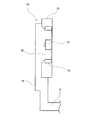
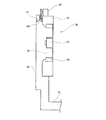
図11は本発明の実施の形態3に係る空気調和機の室内機における吸排気装置を概念的に示した図である。
図11に示すように、この空気調和機における室内機1には、吸排気ファン34を回転させる吸排気モータ33の回転数を制御する制御部43が設けられている。この制御部43は、換気用開口部40を閉塞して塵埃を吸い込む吸塵運転時と、換気用開口部40を開放して室内の空気を吸い込む換気運転時とで吸排気ファン34の回転数を異ならしめるように制御する。例えば、吸塵運転時には、吸い込みノズル16のみから空気を吸引排気することとなり、吸い込みノズル16および換気用開口部40の2箇所から空気を吸引排気する場合に比べて吸排気ファン34への負荷が大きくなるので、吸排気ファン34の回転数を高くする。
FIG. 11 is a diagram conceptually showing an intake / exhaust device in an indoor unit of an air conditioner according to Embodiment 3 of the present invention.
As shown in FIG. 11, the indoor unit 1 in this air conditioner is provided with a control unit 43 that controls the rotation speed of the intake / exhaust motor 33 that rotates the intake / exhaust fan 34. The controller 43 controls the rotational speed of the intake / exhaust fan 34 during the dust suction operation in which the ventilation opening 40 is closed and the dust is sucked in, and in the ventilation operation in which the ventilation opening 40 is opened and the room air is sucked in. Control to make them different. For example, during the dust suction operation, air is sucked and exhausted only from the suction nozzle 16, and the load on the suction and exhaust fan 34 is larger than when suctioning and exhausting air from the suction nozzle 16 and the ventilation opening 40. Therefore, the rotational speed of the intake / exhaust fan 34 is increased.

この構成によれば、吸塵運転時と換気運転時とのそれぞれの場合における最適の排塵風量と換気風量を実現することができる。したがって、吸塵の際にはエアフィルタ8の塵埃を極めて良好に吸い込むことができ、また、換気運転時には、換気に適した量の室内空気を吸い込むことができる。   According to this configuration, it is possible to realize the optimum dust exhaust air volume and ventilation air volume in each case of the dust suction operation and the ventilation operation. Therefore, the dust of the air filter 8 can be sucked very well during the dust suction, and an amount of room air suitable for ventilation can be sucked during the ventilation operation.

なお、上記の場合は、吸排気ファン34の回転数を吸塵運転時に換気運転時よりも大きく設定した場合を述べたが、これに限るものではなく、吸い込みノズル16の吸い込み孔16aの合計開口面積や吸引カバー36の換気用開口部40の開口面積などに応じて、それぞれ最適な回転数を設定すればよい。
(実施の形態4)
次に、本発明の実施の形態4を、図12を用いて説明する。
In the above case, the case where the rotational speed of the intake / exhaust fan 34 is set larger during dust suction operation than during ventilation operation is described, but the present invention is not limited to this, and the total opening area of the suction holes 16a of the suction nozzle 16 In addition, an optimum rotational speed may be set in accordance with the opening area of the ventilation opening 40 of the suction cover 36 or the like.
(Embodiment 4)
Next, Embodiment 4 of the present invention will be described with reference to FIG.

図12は本発明の実施の形態4における空気調和機の室内機の側面断面図である。
図12に示すように、この空気調和機における室内機1では、遠心式の吸排気ファン34として、ラジアルファンが用いられている。
FIG. 12 is a side sectional view of an air conditioner indoor unit according to Embodiment 4 of the present invention.
As shown in FIG. 12, in the indoor unit 1 in this air conditioner, a radial fan is used as the centrifugal intake / exhaust fan 34.

この構成によれば、ラジアルファンは、シロッコファンより、かかる負荷が大きい時にも、低騒音を実現できるので、エアフィルタ8からの塵埃を除去するときの、吸引排気装置30の運転騒音を低減することができる。   According to this configuration, the radial fan can realize low noise even when the load is larger than the sirocco fan. Therefore, the operation noise of the suction / exhaust device 30 when removing dust from the air filter 8 is reduced. be able to.

なお、吸排気ファン34としては、シロッコファンやラジアルファンなどの遠心式のものを用いると、上述したように、吸排気装置30の高風量、低騒音、小型化などの点で複数の利点を有するが、これに限るものではなく、遠心式以外の軸流ファンや斜流ファンなどを用いることも可能である。   If a centrifugal fan such as a sirocco fan or a radial fan is used as the intake / exhaust fan 34, as described above, the intake / exhaust device 30 has a plurality of advantages in terms of high air volume, low noise, miniaturization, and the like. However, the present invention is not limited to this, and it is possible to use an axial flow fan or a mixed flow fan other than the centrifugal type.

また、上記何れの実施の形態においても、吸い込みノズル16を移動させてエアフィルタ8の塵埃を除去する場合を述べたが、これに限るものではなく、吸い込みノズル16からの吸引力を増大させることで、吸い込みノズル16を移動させなくてもエアフィルタ8の塵埃を除去することは可能であり、さらには、エアフィルタ8を設けなくても、室内機1内に付着した塵埃を吸い込んで室外に排出することも可能である。   In any of the above embodiments, the suction nozzle 16 is moved to remove the dust from the air filter 8. However, the present invention is not limited to this, and the suction force from the suction nozzle 16 is increased. Thus, it is possible to remove the dust from the air filter 8 without moving the suction nozzle 16. Furthermore, even if the air filter 8 is not provided, the dust attached to the indoor unit 1 is sucked into the outdoor unit. It is also possible to discharge.

本発明にかかる空気調和機は、空気調和機以外の、室外に排気可能な環境に設置される機器に対しても適用可能である。   The air conditioner according to the present invention can be applied to devices installed in an environment that can be exhausted outside the room, other than the air conditioner.

本発明の実施の形態1における空気調和機の室内機の正面外観図である。It is a front external view of the indoor unit of the air conditioner in Embodiment 1 of the present invention. 同室内機の図1におけるI−I線で矢視した断面図である。It is sectional drawing which saw the arrow of the indoor unit in the II line in FIG. 同室内機の図1におけるII−II線で矢視した断面図である。FIG. 2 is a cross-sectional view taken along the line II-II in FIG. 1 of the indoor unit. 同室内機のエアフィルタおよびその清掃機構に関する構造を示した斜視図である。It is the perspective view which showed the structure regarding the air filter of the indoor unit, and its cleaning mechanism. 同室内機に設けられた吸排気装置の簡略的な側面図である。It is a simplified side view of the intake / exhaust device provided in the indoor unit. 同吸排気装置の斜視図である。It is a perspective view of the same intake / exhaust device. 同吸排気装置の概略的な正面断面図である。It is a rough front sectional view of the intake and exhaust device. 本発明の第2の実施の形態における空気調和機の室内機の側面断面図である。It is side surface sectional drawing of the indoor unit of the air conditioner in the 2nd Embodiment of this invention. 同空気調和機の室内機における吸排気装置の斜視図である。It is a perspective view of the intake / exhaust device in the indoor unit of the air conditioner. 同吸排気装置の概略的な正面断面図である。It is a rough front sectional view of the intake and exhaust device. 本発明の第3の実施の形態に係る空気調和機の室内機における吸排気装置および制御部を概念的に示す図である。It is a figure which shows notionally the intake / exhaust apparatus and control part in the indoor unit of the air conditioner which concerns on the 3rd Embodiment of this invention. 本発明の第4の実施の形態に係る空気調和機の室内機の吸排気装置の側面断面図である。It is side surface sectional drawing of the intake / exhaust apparatus of the indoor unit of the air conditioner which concerns on the 4th Embodiment of this invention. 従来の空気調和機の室内機の断面図である。It is sectional drawing of the indoor unit of the conventional air conditioner. 同従来の空気調和機の室内機におけるエアフィルタおよびその清掃機構に関する構造を示した斜視図である。It is the perspective view which showed the structure regarding the air filter and its cleaning mechanism in the indoor unit of the conventional air conditioner.

符号の説明Explanation of symbols

1 室内機
5 吸い込み部
6 吸い込み部
7 吹き出し部
8 エアフィルタ
9 熱交換器
9A 熱交換器
9B 熱交換器
10 送風ファン
15 吸い込みダクト
16 吸い込みノズル
16a 吸い込み孔
17 排気ダクト17
18 ねじ軸
21 ノズル駆動用モータ
30 吸排気装置
31 吸い込みダクト接続口
32 排気ダクト接続口
33 吸排気モータ
34 吸排気ファン
35 ケーシング
36 吸引カバー
38 吸い込み口
40 換気用開口部
41 開閉体
42 開閉用駆動手段
43 制御部
DESCRIPTION OF SYMBOLS 1 Indoor unit 5 Suction part 6 Suction part 7 Blowout part 8 Air filter 9 Heat exchanger 9A Heat exchanger 9B Heat exchanger 10 Blower fan 15 Suction duct 16 Suction nozzle 16a Suction hole 17 Exhaust duct 17
18 Screw shaft 21 Nozzle drive motor 30 Intake / exhaust device 31 Suction duct connection port 32 Exhaust duct connection port 33 Suction / exhaust motor 34 Suction / exhaust fan 35 Casing 36 Suction cover 38 Suction port 40 Ventilation opening 41 Opening / closing body 42 Opening / closing drive Means 43 Controller

Claims (8)

室内機に付着した塵埃を吸込む吸込み孔を有する吸込みノズルと、前記吸込みノズルに接続された吸排気装置とを少なくとも有するフィルター清掃装置を備え、前記フィルター清掃装置に一端に接続され、他端が室外に連通された排気ダクトとを備えた空気調和機であって、前記吸排気装置によって前記フィルター清掃装置に吸込まれた塵埃と室内側空気のいずれか一方または双方を排出することを特徴とする空気調和機。 A filter cleaning device having at least a suction nozzle having a suction hole for sucking dust adhering to the indoor unit, and an intake / exhaust device connected to the suction nozzle, and connected to one end of the filter cleaning device, the other end being the outdoor An air conditioner having an exhaust duct communicated with the air, wherein either or both of dust and indoor air sucked into the filter cleaning device by the intake and exhaust device are discharged. Harmony machine. フィルター清掃装置に換気用開口部及び前記換気用開口部を開閉する開閉体を設け、前記換気用開口部及び前記換気用開口部を開閉する開閉体の開時に室内の空気と吸排気装置を連通することを特徴とする請求項1に記載の空気調和機。 The filter cleaning device is provided with a ventilation opening and an opening / closing body for opening and closing the ventilation opening, and when the opening for opening and closing the ventilation opening and the opening for ventilation is opened, indoor air communicates with the intake / exhaust device The air conditioner according to claim 1. 換気用開口部及び前記換気用開口部を開閉する開閉体は、吸込みノズルと吸排気装置の間に設けられたことを特徴とする請求項2に記載の空気調和機。 The air conditioner according to claim 2, wherein the ventilation opening and the opening / closing body that opens and closes the ventilation opening are provided between the suction nozzle and the intake / exhaust device. 換気用開口部及び前記換気用開口部を開閉する開閉体は、吸排気装置に設けられたことを特徴とする請求項2に記載の空気調和機。 The air conditioner according to claim 2, wherein the ventilation opening and the opening / closing body that opens and closes the ventilation opening are provided in the intake / exhaust device. 換気用開口部及び前記換気用開口部を開閉する開閉体は、吸込みノズルに設けられたことを特徴とする請求項2に記載の空気調和機。 The air conditioner according to claim 2, wherein the ventilation opening and the opening / closing body for opening and closing the ventilation opening are provided in a suction nozzle. 換気用開口部及び前記換気用開口部を開閉する開閉体は開口部を有し、前記開口部は室内側空気を通過させることを特徴とする請求項2〜5のいずれか1項に記載の空気調和機。 The opening / closing body for opening / closing the ventilation opening and the ventilation opening has an opening, and the opening allows the indoor air to pass therethrough. Air conditioner. 吸排気装置は少なくとも、塵埃を吸込む排塵ファンと、塵埃と前記フィルター清掃装置に吸い込まれた室内側空気のいずれか一方または双方を排出する給排気ファンとを有することを特徴とする請求項1〜6のいずれか1項に記載の空気調和機。 2. The intake / exhaust device includes at least a dust exhaust fan that sucks dust, and an air supply / exhaust fan that exhausts one or both of dust and indoor air sucked into the filter cleaning device. The air conditioner of any one of -6. 吸排気装置は単一の給排気ファンを備えたことを特徴とする請求項7に記載の空気調和機。 The air conditioner according to claim 7, wherein the intake / exhaust device includes a single supply / exhaust fan.
JP2005357080A 2003-09-12 2005-12-12 Air conditioner Expired - Fee Related JP3992722B2 (en)

Priority Applications (1)

Application Number Priority Date Filing Date Title
JP2005357080A JP3992722B2 (en) 2003-09-12 2005-12-12 Air conditioner

Applications Claiming Priority (3)

Application Number Priority Date Filing Date Title
JP2003320639 2003-09-12
JP2005357080A JP3992722B2 (en) 2003-09-12 2005-12-12 Air conditioner

Related Parent Applications (1)

Application Number Title Priority Date Filing Date
JP2005513944A Division JP3923067B2 (en) 2003-09-12 2004-09-08 Air conditioner

Publications (3)

Publication Number Publication Date
JP2006183997A JP2006183997A (en) 2006-07-13
JP2006183997A6 true JP2006183997A6 (en) 2006-10-26
JP3992722B2 JP3992722B2 (en) 2007-10-17

Family

ID=36737237

Family Applications (1)

Application Number Title Priority Date Filing Date
JP2005357080A Expired - Fee Related JP3992722B2 (en) 2003-09-12 2005-12-12 Air conditioner

Country Status (1)

Country Link
JP (1) JP3992722B2 (en)

Families Citing this family (5)

* Cited by examiner, † Cited by third party
Publication number Priority date Publication date Assignee Title
KR101270619B1 (en) 2006-12-08 2013-06-07 엘지전자 주식회사 Air conditioner
KR101305325B1 (en) 2006-12-08 2013-09-09 엘지전자 주식회사 Air conditioner
JP4807266B2 (en) * 2007-01-19 2011-11-02 パナソニック株式会社 Air conditioner
JP5292737B2 (en) * 2007-06-21 2013-09-18 ダイキン工業株式会社 Dust collection box and air conditioner equipped with the same
CN108940594B (en) * 2017-05-18 2023-09-22 江苏瑞洁环境工程科技有限责任公司 Wet-type electric dust remover

Similar Documents

Publication Publication Date Title
JP3923067B2 (en) Air conditioner
JP2006183996A6 (en) Air conditioner
JP2006183996A (en) Air conditioner
JP3992722B2 (en) Air conditioner
JP2008002767A (en) Indoor unit of air conditioner
KR100917725B1 (en) Indoor unit of air-conditioner
JP2006183997A6 (en) Air conditioner
JP2004156794A (en) Air conditioner
JP4823875B2 (en) Vacuum cleaner suction port
JP4533366B2 (en) Filter, filter cleaning device, and air conditioner
JP4909699B2 (en) Air conditioner indoor unit
JP4860131B2 (en) Method for controlling dust suction device of air conditioner
JP4878521B2 (en) Air conditioner indoor unit
JPWO2007145254A1 (en) Air conditioner indoor unit
KR20060054075A (en) Air conditioner
JP4165246B2 (en) Air conditioner
JP4134768B2 (en) Air conditioner
JPWO2004083735A1 (en) Air conditioner with indoor unit with automatic air filter cleaning function
JP4202822B2 (en) Air conditioner
JP2007127289A (en) Air conditioner
JP2008039293A (en) Indoor unit of air conditioner
JP2004278923A (en) Air conditioner
JP2008121965A (en) Indoor unit of air conditioner
JP2004353966A (en) Air conditioner
JP2008002689A (en) Indoor unit of air conditioner