JP2006181237A - Game machine and article for game - Google Patents

Game machine and article for game Download PDF

Info

Publication number
JP2006181237A
JP2006181237A JP2004380201A JP2004380201A JP2006181237A JP 2006181237 A JP2006181237 A JP 2006181237A JP 2004380201 A JP2004380201 A JP 2004380201A JP 2004380201 A JP2004380201 A JP 2004380201A JP 2006181237 A JP2006181237 A JP 2006181237A
Authority
JP
Japan
Prior art keywords
game
light emission
light
player
gaming machine
Prior art date
Legal status (The legal status is an assumption and is not a legal conclusion. Google has not performed a legal analysis and makes no representation as to the accuracy of the status listed.)
Granted
Application number
JP2004380201A
Other languages
Japanese (ja)
Other versions
JP4723238B2 (en
Inventor
Kenichi Yagi
健一 八木
Current Assignee (The listed assignees may be inaccurate. Google has not performed a legal analysis and makes no representation or warranty as to the accuracy of the list.)
Universal Entertainment Corp
Original Assignee
Aruze Corp
Priority date (The priority date is an assumption and is not a legal conclusion. Google has not performed a legal analysis and makes no representation as to the accuracy of the date listed.)
Filing date
Publication date
Application filed by Aruze Corp filed Critical Aruze Corp
Priority to JP2004380201A priority Critical patent/JP4723238B2/en
Priority to AU2005246947A priority patent/AU2005246947A1/en
Priority to ZA200510437A priority patent/ZA200510437B/en
Priority to EP05258024A priority patent/EP1677265A1/en
Priority to US11/317,895 priority patent/US20060183543A1/en
Priority to EA200501877A priority patent/EA009774B1/en
Priority to CNA2005101357318A priority patent/CN1810338A/en
Publication of JP2006181237A publication Critical patent/JP2006181237A/en
Application granted granted Critical
Publication of JP4723238B2 publication Critical patent/JP4723238B2/en
Active legal-status Critical Current
Anticipated expiration legal-status Critical

Links

Images

Abstract

<P>PROBLEM TO BE SOLVED: To provide a game machine and an article for the games which enable the maintenance of the interests of the players without replacing the article for the games. <P>SOLUTION: In the game machine 10, when the emission mode of an LED 21 is changed based on the figure ID stored in an IC chip 34 of a figure 30, the light emitted from an emission part 32b of the figure 30 varies, thereby making the appearance of the figure look different. In other words, the game machine 10 can causes a difference in the appearance of the figure 30 without replacing the figure 30, thereby enabling the sufficient maintenance of the interests of the players. <P>COPYRIGHT: (C)2006,JPO&NCIPI

Description

本発明は、遊技用物品を利用した遊技が可能な遊技機、及びこれに利用される遊技用物品に関するものである。   The present invention relates to a gaming machine capable of playing games using gaming items, and gaming items used for the gaming machines.

従来、それぞれの遊技に関連する情報(遊技情報)が記憶されたフィギア(フィギュアともいう。)やフィギア付きカートリッジが、例えば、下記特許文献1や特許文献2等に開示されている。これらの遊技機の遊技者は、遊技状態に応じてフィギア等(以下、遊技用物品とも称す。)を交換することができ、遊技者を飽きさせたり退屈させたりしないような配慮がなされている。
特開2003−230761号公報 特開2002−126345号公報
Conventionally, a figure (also referred to as a figure) in which information (game information) related to each game is stored and a cartridge with a figure are disclosed in, for example, Patent Document 1 and Patent Document 2 below. Players of these gaming machines can exchange figures and the like (hereinafter also referred to as gaming items) according to the gaming state, and consideration is given to not bored or bored players. .
JP 2003-230761 A JP 2002-126345 A

しかしながら、前述した従来の遊技機には、次のような課題が存在している。すなわち、遊技者側は、飽きや退屈を感じるたびに新たな遊技用物品を購入する等して、いくつもの遊技用物品を用意しなければならなかった。一方、遊技用物品の販売等をする提供者側も、遊技者に常に新鮮味を感じてもらえるような斬新な遊技用物品を絶えず開発し続けなければならないという苦労があった。そのため、遊技者側にとっても提供者側にとっても、新たな遊技用物品をいくつも用意する必要がなく、飽きや退屈を感じずに遊技を楽しむことができる遊技機の登場が待ち望まれている。   However, the following problems exist in the conventional gaming machine described above. That is, the player side has to prepare several game items by purchasing new game items each time he feels bored or bored. On the other hand, the provider side who sells game items has had a hard time to constantly develop innovative game items that always allow players to feel fresh. Therefore, it is not necessary for the player side and the provider side to prepare a number of new game items, and there is a long-awaited appearance of a gaming machine that can enjoy the game without feeling bored or bored.

そこで、本発明は、上述の課題を解決するためになされたもので、遊技用物品の交換をしなくても、遊技者の興趣を保つことが可能な遊技機及び遊技用物品を提供することを目的とする。   Accordingly, the present invention has been made to solve the above-described problems, and provides a gaming machine and a gaming article that can maintain the interest of the player without exchanging gaming articles. With the goal.

本発明に係る遊技機は、外部から入射される光を内部へ導く入射部と入射部から入射されて内部を透過した光を外部に出射する出射部とを有する本体部と遊技に関する遊技情報を記憶している記憶部とを備える遊技用物品から、遊技情報の読み取りを行う読取手段と、読取手段によって読み取られた遊技情報に基づいて、遊技用物品の入射部に対して投光する発光体の発光態様を決定する発光態様決定手段と、発光態様決定手段によって決定された発光態様に従って、発光体の発光制御を行う発光制御手段とを備えることを特徴とする。   A gaming machine according to the present invention has a main body portion having an incident portion that guides light incident from the outside to the inside, and an emission portion that emits light incident from the incident portion and transmitted through the inside, and game information related to the game. Reading means for reading game information from a gaming article having a storage section stored therein, and a light emitter that projects light on an incident portion of the gaming article based on the gaming information read by the reading means And a light emission control means for performing light emission control of the light emitter in accordance with the light emission mode determined by the light emission mode determination means.

この遊技機においては、読取手段によって遊技用物品の記憶部から遊技情報が読み取られると、発光態様決定手段が、その遊技情報に基づいて発光体の発光態様を決定すると共に、発光制御手段が、発光態様決定手段によって決定された発光態様に従って発光体の発光制御を行う。そして、この発光体から遊技用物品の入射部に対して投光された光は、遊技用物品の本体部内を透過して出射部から外部に出射される。従って、この遊技機においては、遊技用物品に記憶された遊技情報に基づき発光体の発光態様を変化させると、遊技者に対して視認可能に配置された遊技機用物品の出射部から出射される光が変化し、遊技用物品の外観が変わって見える。すなわち、本発明に係る遊技機は、遊技用物品の交換をすることなく、遊技用物品の外観をを変えることができるため、遊技者の興趣が保たれる。   In this gaming machine, when the game information is read from the storage unit of the game article by the reading means, the light emission mode determination means determines the light emission mode of the light emitter based on the game information, and the light emission control means The light emission of the light emitter is controlled in accordance with the light emission mode determined by the light emission mode determination means. The light projected from the light emitter to the incident portion of the gaming article is transmitted through the main body portion of the gaming article and emitted from the emitting portion to the outside. Therefore, in this gaming machine, when the light emission mode of the light emitter is changed based on the game information stored in the gaming article, the gaming machine emits the light from the emitting section of the gaming machine article arranged so as to be visible to the player. As the light changes, the appearance of the game item appears to change. That is, the gaming machine according to the present invention can change the appearance of the gaming article without exchanging the gaming article, so that the player's interest is maintained.

また、発光体が、遊技用物品の入射部に対して複数色の光を投光可能であることが好ましい。この場合、より多様性に富んだ発光態様を実現することができる。   In addition, the light emitter is preferably capable of projecting a plurality of colors of light to the incident portion of the game article. In this case, more diverse light emission modes can be realized.

また、遊技機に発光体が設けられていることが好ましい。遊技者各々が遊技用物品を所有する場合には、遊技機の数よりも遊技用物品の数の方が格段に多くなるため、各遊技機用物品に発光体を設ける場合に比べて用意する発光体の数を減らすことができる。   Moreover, it is preferable that the game machine is provided with a light emitter. When each player owns a game article, the number of game articles is significantly larger than the number of game machines, so prepare for the case where a light emitter is provided for each game machine article. The number of light emitters can be reduced.

また、遊技用物品が発光体を有していることが好ましい。この場合、遊技用物品毎に、例えば、色や色数が異なる発光体を設けることができ、遊技用物品毎に異なる発光態様を実現することができる。さらに、発光体が遊技機に設けられている場合に比べ、多様性に富んだ発光態様を容易に実現することができる。   Moreover, it is preferable that the game article has a light emitter. In this case, for example, a light emitter having a different color or number of colors can be provided for each gaming article, and a different light emission mode can be realized for each gaming article. Furthermore, a variety of light emission modes can be easily realized as compared with the case where the light emitter is provided in the gaming machine.

また、遊技に用いられる遊技画像を画像表示手段に表示させる遊技機であり、遊技者が遊技画像を用いた画像遊技の進行に必要な操作入力を行う操作手段と、画像表示手段に遊技画像を表示させ画像遊技を進行させる遊技進行制御手段と、画像遊技に関連する遊技関連情報を外部から受信する通信手段とを備え、発光態様決定手段は、通信手段によって受信した遊技関連情報と、読取手段によって読み取られた遊技情報とに基づいて発光体の発光態様を決定することが好ましい。この場合、発光態様決定手段は、遊技情報だけでなく通信手段によって受信された外部からの遊技関連情報にも基づいて発光体の発光態様を決定するため、多様性に富んだ発光態様を実現することができ、それにより遊技者の興趣が保たれる。   Also, a gaming machine for displaying a game image used in a game on an image display means, wherein a player inputs an operation input necessary for progress of an image game using the game image, and a game image is displayed on the image display means. A game progress control means for displaying and advancing the image game; and a communication means for receiving game-related information related to the image game from the outside. The light emission mode determining means includes the game-related information received by the communication means, and a reading means. It is preferable to determine the light emission mode of the light emitter based on the game information read by. In this case, since the light emission mode determination means determines the light emission mode of the light emitter based not only on the game information but also on the external game-related information received by the communication means, it realizes a variety of light emission modes. And it keeps the player's interest.

また、遊技態様として通常遊技態様と遊技者にとって有利な特典が付与される特別遊技態様とを有し、所定の移行条件の成立によって遊技態様を通常遊技態様から特別遊技態様へ移行させる遊技態様制御手段をさらに備えることが好ましい。遊技者は特別遊技態様への移行を期待しつつ遊技を繰り返すが、発光態様を変化させることで遊技者の期待感が膨らむため、遊技者の興趣が保たれる。   In addition, the game mode control has a normal game mode and a special game mode which is given a privilege advantageous to the player as the game mode, and the game mode is shifted from the normal game mode to the special game mode when a predetermined transition condition is established. Preferably further means are provided. The player repeats the game while expecting a transition to the special game mode, but the player's interest is maintained because the player's expectation expands by changing the light emission mode.

本発明に係る遊技用物品は、遊技機の遊技に関する遊技情報が記憶される記憶部と、発光体から入射される光を内部へ導く入射部と、入射部から入射されて内部を透過した光を外部に出射する出射部とを有する本体部とを備えることを特徴とする。   A gaming article according to the present invention includes a storage unit that stores game information relating to gaming of a gaming machine, an incident unit that guides light incident from a light emitter, and light that is incident from the incident unit and transmitted through the interior. And a main body having an emission part for emitting the light to the outside.

この遊技用物品においては、発光体から本体部の入射部に対して光が投光されると、その光は、本体部内を透過して出射部から外部に出射される。従って、この遊技機用物品を、例えば、記憶部に記憶された遊技情報に基づいて発光体の発光態様を変化させることが可能な遊技機に用いた場合には、遊技者に対して視認可能に配置される遊技機用物品の出射部から出射される光が変化して、遊技用物品の本体部の外観が変わって見える。すなわち、本発明に係る遊技機用物品を用いる遊技機においては、遊技用物品の交換をすることなく、遊技用物品の外観をを変えることができるため、遊技者の興趣が保たれる。   In this gaming article, when light is projected from the light emitter to the incident portion of the main body, the light is transmitted through the main body and emitted from the emitting portion to the outside. Therefore, when this gaming machine article is used for a gaming machine capable of changing the light emission mode of the light emitter based on the gaming information stored in the storage unit, for example, it can be visually recognized by the player. The light emitted from the emitting part of the gaming machine article arranged on the board changes, and the appearance of the main body part of the gaming article changes. That is, in the gaming machine using the gaming machine article according to the present invention, the appearance of the gaming article can be changed without exchanging the gaming article, so that the player's interest is maintained.

本発明によれば、遊技用物品の交換をしなくても、遊技者の興趣を保つことが可能な遊技機及び遊技用物品が提供される。   ADVANTAGE OF THE INVENTION According to this invention, the game machine and game article which can maintain a player's interest are provided, without exchanging game articles.

以下、添付図面を参照して本発明に係る遊技機及び遊技機用物品を実施するにあたり最良と思われる形態について詳細に説明する。なお、同一又は同等の要素については同一の符号を付し、説明が重複する場合にはその説明を省略する。
第1実施形態
(ゲームシステムの全体構成)
DETAILED DESCRIPTION OF THE PREFERRED EMBODIMENTS Hereinafter, embodiments that are considered to be the best for carrying out a gaming machine and an article for a gaming machine according to the present invention will be described in detail with reference to the accompanying drawings. In addition, the same code | symbol is attached | subjected about the same or equivalent element, and the description is abbreviate | omitted when description overlaps.
First Embodiment (Overall Configuration of Game System)

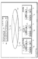
図1は本発明に係るゲームマシンを複数備えたゲームシステムのシステム構成図、図2は複数のゲームマシンとカード販売機を示す斜視図である。ゲームシステム1は、2つの遊技店舗A,Bにそれぞれ1台および2台設置された合計3台の店舗サーバ2と、専用回線Cを介して通信可能に接続された複数(本実施の形態では8台)のゲームマシン10およびカード販売機3と、遊技店舗A,Bに設置された店舗内ルータ4と、店舗内ルータ4、通信回線CおよびインターネットNTを介して接続されたセンターサーバ群5とを有している。 FIG. 1 is a system configuration diagram of a game system including a plurality of game machines according to the present invention, and FIG. 2 is a perspective view showing a plurality of game machines and a card vending machine. The game system 1 includes a plurality of store servers 2 (one and two installed in two game stores A and B, respectively), and a plurality of game servers 1 connected to each other via a dedicated line C 1 (this embodiment). 8) gaming machines 10 and card vending machines 3, in-store routers 4 installed in game stores A and B, in-store routers 4, communication lines C 2 and a center server connected via the Internet NT And Group 5.

各遊技店舗A,Bでは、店舗サーバ2と、ゲームマシン10およびカード販売機3が専用回線Cにより接続されて店舗内LAN(Local Area Network)を形成し、この店舗内LANが店舗内ルータ4を介してインターネットNTに接続されている。 Each game shops A, in B, with the shop server 2, the gaming machine 10 and the card machine 3 is connected by a dedicated line C 1 form a store LAN (Local Area Network), store in the router this store LAN is 4 is connected to the Internet NT.

ゲームシステム1を構成している各ゲームマシン10は、本発明の第1実施形態に係る遊技機であって、各ゲームマシン10には、自機固有のマシンIDが付与されている。このマシンIDは、各店舗サーバ2に固有のサーバIDと、各ゲームマシン10に固有のIDとを有し、例えば、店舗Aに設置されている各ゲームマシン10の場合、A01,A02,A03・・・のようになっている。
(ゲームマシンの構成)
Each game machine 10 constituting the game system 1 is a gaming machine according to the first embodiment of the present invention, and each game machine 10 is assigned a machine ID unique to the game machine 10. This machine ID has a server ID unique to each store server 2 and an ID unique to each game machine 10. For example, in the case of each game machine 10 installed in the store A, A01, A02, A03 ... and so on.
(Game machine configuration)

ゲームマシン10は、遊技に用いられる遊技画像として、遊技に用いられる遊技画像として、遊技者の操作に応じて行動するキャラクタを示すキャラクタ画像を表示する画像表示手段を有し、遊技者の操作に応じた動作をキャラクタに行わせる画像遊技を行えるように構成されている。本実施の形態におけるゲームマシン10では、遊技者の選択したルートに沿ってキャラクタが迷宮内を移動しながら、自分以外の別キャラクタ(他の遊技者の選択にしたがい動作を行うプレイヤーキャラクタや、ゲームマシンが動作を行わせるノンプレイヤーキャラクタ)と対戦して、キャラクタが持つアイテムを奪い合い、そのアイテムをすべて集めた上で最終目標のキャラクタを倒すゲーム(以下、「迷宮対戦ゲーム」という)を行えるようになっている。この迷宮対戦ゲームでは、対戦結果やゲームの進行状況に合わせて各キャラクタの持点(本実施の形態では「ライフ」という)が昇降し、その持点が無くなったキャラクタが敗者となるようになっている。   The game machine 10 includes image display means for displaying a character image indicating a character acting in response to the player's operation as a game image used for the game as a game image used for the game. An image game that causes the character to perform a corresponding action is configured. In the gaming machine 10 according to the present embodiment, the character moves in the labyrinth along the route selected by the player, while another character (a player character that performs an action in accordance with the selection of another player, a game, You can play a game where you can play against a non-player character that makes the machine move, scramble for the items that the character has, collect all the items, and then defeat the final target character (hereinafter referred to as the “Maze Battle Game”) It has become. In this labyrinth battle game, the score of each character (referred to as “life” in the present embodiment) moves up and down according to the match result and the progress of the game, and the character that has lost the score becomes a loser. ing.

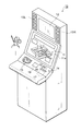
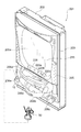
ゲームマシン10は、図3に示すように、筐体の正面に、液晶表示装置を備えたメインディスプレイ11を有している。また、メインディスプレイ11の上側部分に同じく液晶表示装置を備えたサブディスプレイ12を有し、その左右両側に遊技の演出に用いられる音声を出力するスピーカ13L,13Rが配置されている。   As shown in FIG. 3, the game machine 10 has a main display 11 including a liquid crystal display device on the front surface of the housing. In addition, the upper portion of the main display 11 has a sub-display 12 that is also provided with a liquid crystal display device, and speakers 13L and 13R that output sounds used for game effects are arranged on the left and right sides thereof.

メインディスプレイ11は、遊技の各段階に応じた遊技画像(例えば、迷宮画像など)が表示されるようになっている。サブディスプレイ12は、遊技の特定の段階における画像(例えば、対戦画像)が表示されるようになっている。なお、本実施形態の画像表示手段は、メインディスプレイ11とサブディスプレイ12とによって構成されている。   The main display 11 displays game images (for example, labyrinth images) according to each stage of the game. The sub display 12 displays an image (for example, a battle image) at a specific stage of the game. Note that the image display means of this embodiment includes a main display 11 and a sub display 12.

また、ゲームマシン10はメインディスプレイ11の下側に操作パネル14を有しており、この操作パネル14の左側にフィギア設置ユニット15が配置されている。また、操作パネル14の右側には、ゲームを実行するときに必要なコイン(硬貨、遊技用メダルなどの遊技媒体)を投入するコイン投入口16と、IDカード17を挿入するためのカードスロット18とが設けられており、操作パネル14の中央付近には操作ボタンなどを備えた操作ユニット19が設けられている。   The game machine 10 has an operation panel 14 below the main display 11, and a figure installation unit 15 is disposed on the left side of the operation panel 14. Also, on the right side of the operation panel 14, a coin insertion slot 16 for inserting coins (game media such as coins and game medals) necessary for executing a game, and a card slot 18 for inserting an ID card 17 are inserted. In the vicinity of the center of the operation panel 14, an operation unit 19 having operation buttons and the like is provided.

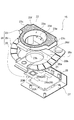
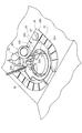
ここで、フィギア設置ユニット15について、図4を参照しつつ説明する。図4は、フィギア設置ユニット15の分解斜視図である。フィギア設置ユニット15は、後述するフィギア30からフィギア記憶情報をICチップリーダライタ20によって読み取れるようにフィギア30を保持するものであり、保持したフィギア30に対して投光するフルカラーLED(発光体)21と、フィギア30を保持する保持孔22が形成され、保持孔22の周壁面23aとLED21との間に光透過領域が形成されたホルダー部24とを有し、ホルダー部24の下方にはICチップリーダライタ20が配置されている。   Here, the figure installation unit 15 will be described with reference to FIG. FIG. 4 is an exploded perspective view of the figure installation unit 15. The figure installation unit 15 holds the figure 30 so that the figure memory information can be read by the IC chip reader / writer 20 from the figure 30 described later, and a full color LED (light emitting body) 21 that projects light on the held figure 30. And a holder part 24 in which a holding hole 22 for holding the figure 30 is formed, and a light transmission region is formed between the peripheral wall surface 23 a of the holding hole 22 and the LED 21. A chip reader / writer 20 is arranged.

ホルダー部24は、内側に保持孔22を有し、透明ウレタン等の無色透明な光透過性部材からなる保持部材23と、保持部材23を側方および下方から保持する保持フレーム26と、ゲームマシン10の操作パネル14に保持フレーム26を固定する基台27とを有している。   The holder portion 24 has a holding hole 22 inside, a holding member 23 made of a colorless and transparent light-transmitting member such as transparent urethane, a holding frame 26 that holds the holding member 23 from the side and below, and a game machine A base 27 for fixing the holding frame 26 to the ten operation panels 14 is provided.

保持部材23は、保持孔22を内側に有する概ね円環状に形成されており、手前側(遊技者側)に設けられた突出部23bと、背面側に幅が広くなるように設けられた幅広部23c,23cと、上部表面(保持孔22が形成された周壁面23aを除く)に貼着された遮光シール23fを有する。保持部材23は突出部23bの下面が保持フレーム26に組み付けられ、且つ、幅広部23c,23cが保持フレーム26に挟まれて保持されている。   The holding member 23 is formed in a generally annular shape having a holding hole 22 on the inside, and has a protruding portion 23b provided on the front side (player side) and a wide width provided on the back side so as to be wide. And a light shielding seal 23f attached to the upper surface (excluding the peripheral wall surface 23a in which the holding hole 22 is formed). In the holding member 23, the lower surface of the protruding portion 23b is assembled to the holding frame 26, and the wide portions 23c and 23c are held between the holding frames 26.

また、保持部材23は、保持孔22に臨む基台27側(保持フレーム26の装着部26aによって閉塞される側)の円形の開口部23dと開放されている側の円形の開放端部23eとを備え、開放端部23eの直径が開口部23dの直径よりも大きく、開放端部23eと開口部23dとの間の周壁面23aが、開放端部23eから開口部23dに向かって漸次縮径しながらつながるすり鉢状の傾斜面となっている。開口部23dの形状が、後述するフィギア30の底部の形状に対応しており、底部が挿通可能になっている。周壁面23aをこのように傾斜させることで、フィギア30をフィギア設置ユニット15にセットする際、フィギア30の底部が周壁面23aに沿って案内されつつ装着部26aまで到達するため、遊技者はフィギア30をフィギア設置ユニット15の正しい読取位置に容易にセットでき、フィギア30を用いたゲームを開始するにあたっての面倒が軽減される。   The holding member 23 includes a circular opening 23d on the side of the base 27 facing the holding hole 22 (a side closed by the mounting portion 26a of the holding frame 26) and a circular open end 23e on the open side. The diameter of the open end 23e is larger than the diameter of the opening 23d, and the peripheral wall surface 23a between the open end 23e and the opening 23d is gradually reduced in diameter from the open end 23e toward the opening 23d. It is a mortar-like inclined surface that connects while. The shape of the opening 23d corresponds to the shape of the bottom of the figure 30 described later, and the bottom can be inserted. By tilting the peripheral wall surface 23a in this way, when the figure 30 is set in the figure installation unit 15, the bottom of the figure 30 reaches the mounting portion 26a while being guided along the peripheral wall surface 23a. 30 can be easily set at the correct reading position of the figure installation unit 15, and troublesomeness in starting a game using the figure 30 is reduced.

保持フレーム26は、保持部材23を囲む環状の枠体26bと、この枠体26bの内側で窪み、保持部材23を保持する保持受け部26cと、保持受け部26cの背面に形成された光透過窓26dと、保持受け部26cの内側略中央にて段差をもって円柱状に窪んだ装着部26aとを備える。装着部26aの開口が、保持部材23の開口部23dの形状に対応して同心で同径の円形になっている。   The holding frame 26 is an annular frame 26b that surrounds the holding member 23, is recessed inside the frame 26b, a holding receiving portion 26c that holds the holding member 23, and a light transmission formed on the back surface of the holding receiving portion 26c. A window 26d and a mounting portion 26a that is recessed in a columnar shape with a step at a substantially inner center of the holding receiving portion 26c are provided. The opening of the mounting portion 26 a is a concentric and circular shape corresponding to the shape of the opening 23 d of the holding member 23.

ICチップリーダライタ20は、本発明の読取手段に相当する回路基板であり、その上面20aにはアンテナ28a及び制御用回路28bを含む読取回路28が形成されている。このICチップリーダライタ20は、制御用回路28b等が形成されている正方形部分20Aと、この正方形部分20Aの一辺から突出し、主にアンテナ28aが形成されている突出部分20Bとで構成されている。そして、ICチップリーダライタ20上に形成された読取回路28により、ICチップリーダライタ20は、フィギア30に記録されている情報(本発明における遊技情報、以下、フィギア記憶情報と称す)を読み取ってメインCPU42に入力し、メインCPU42からの指示に従って所定の情報をICチップ34に書き込む。なお、このICチップリーダライタ20は、約5cm離れた位置にあるICチップ34からでもフィギア記憶情報を読み取ることができる。   The IC chip reader / writer 20 is a circuit board corresponding to the reading means of the present invention, and a reading circuit 28 including an antenna 28a and a control circuit 28b is formed on the upper surface 20a. The IC chip reader / writer 20 includes a square portion 20A in which a control circuit 28b and the like are formed, and a protruding portion 20B that protrudes from one side of the square portion 20A and mainly has an antenna 28a. . Then, by the reading circuit 28 formed on the IC chip reader / writer 20, the IC chip reader / writer 20 reads information recorded in the figure 30 (game information in the present invention, hereinafter referred to as figure storage information). Input to the main CPU 42 and write predetermined information to the IC chip 34 in accordance with an instruction from the main CPU 42. The IC chip reader / writer 20 can read the figure storage information even from the IC chip 34 at a position about 5 cm away.

そして、保持フレーム26とICチップリーダライタ20とは、ICチップリーダライタ20の突出部分20Bと保持フレーム26の装着部26aとが重なるように位置合わせされた状態で、基台55にネジ固定される。そのため、ICチップリーダライタ20は、装着部26aに搭載されたフィギア30のICチップ34に記憶されているフィギア記憶情報を、突出部分20Bに形成されたアンテナ28aを用いて読み書きすることができる。   The holding frame 26 and the IC chip reader / writer 20 are screwed to the base 55 in a state where the protruding portion 20B of the IC chip reader / writer 20 and the mounting portion 26a of the holding frame 26 are aligned. The Therefore, the IC chip reader / writer 20 can read and write the figure storage information stored in the IC chip 34 of the figure 30 mounted on the mounting portion 26a using the antenna 28a formed on the protruding portion 20B.

なお、保持フレーム26の背面側に位置する基台27には、保持フレーム26から所定の間隔だけ離してLED21が配設されている。このLED21は、赤色発光素子、青色発光素子、緑色発光素子を備えているため、各素子から発光される色の組合せにより様々な色の発光をおこなうことができる。また、LED16は、保持フレーム26の光透過窓26dに対応する位置に、この光透過窓26dから露出する保持部材23に対して一定の隙間(5mm程度)だけスペーサ29で保った状態で配設されている。   The LED 21 is disposed on the base 27 located on the back side of the holding frame 26 so as to be separated from the holding frame 26 by a predetermined distance. Since the LED 21 includes a red light emitting element, a blue light emitting element, and a green light emitting element, light of various colors can be emitted by a combination of colors emitted from each element. The LED 16 is disposed at a position corresponding to the light transmission window 26d of the holding frame 26 in a state where it is held by a spacer 29 by a certain gap (about 5 mm) with respect to the holding member 23 exposed from the light transmission window 26d. Has been.

このLED21に後述の発光制御回路50から電力が供給された場合には、その発光の一部が、保持フレーム26の光透過窓26dを通って、透光性を有する保持部材23内に入射される。そして、保持部材23内に入射された光は、保持部材23内を透過して、保持部材23の周壁面23aから出射される。ここで、周壁面23aはセットされるフィギア30を囲む位置にあるため、保持部材23の周壁面23aから出射された光がフィギア設置ユニット15にセットされたフィギア30をその下側から照らすこととなる。
(フィギアの構成)
When electric power is supplied to the LED 21 from a light emission control circuit 50 described later, a part of the light emission is incident on the translucent holding member 23 through the light transmission window 26d of the holding frame 26. The The light that has entered the holding member 23 passes through the holding member 23 and is emitted from the peripheral wall surface 23 a of the holding member 23. Here, since the peripheral wall surface 23a is in a position surrounding the set figure 30, the light emitted from the peripheral wall surface 23a of the holding member 23 illuminates the figure 30 set on the figure installation unit 15 from below. Become.
(Figure structure)

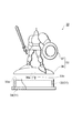
図5はフィギア30の構成を示す正面分解図である。このフィギア30は、台座部31と、迷宮対戦ゲームに登場する各キャラクタの立体形状を表したフィギア本体部32とで構成されている。   FIG. 5 is an exploded front view showing the configuration of the figure 30. The figure 30 includes a pedestal 31 and a figure main body 32 representing the three-dimensional shape of each character appearing in the labyrinth battle game.

台座部31は、保持フレーム26の装着部26aに対応する断面形状を有する厚肉中空円板である。この台座部31は、本発明の記憶部に相当し、天頂部33aを有する有底円筒状の台座本体部33とICチップ34とで構成されている。そして、台座本体部33の天頂部33aの略中央には突起部33bが設けられており、台座本体部33の開口部には、開口部を塞がないようにICチップ34が嵌め込み固定されている。   The pedestal portion 31 is a thick hollow disk having a cross-sectional shape corresponding to the mounting portion 26 a of the holding frame 26. The pedestal portion 31 corresponds to a storage portion of the present invention, and includes a bottomed cylindrical pedestal main body portion 33 having a zenith portion 33 a and an IC chip 34. A protrusion 33b is provided at the approximate center of the zenith 33a of the pedestal main body 33, and the IC chip 34 is fitted and fixed in the opening of the pedestal main body 33 so as not to block the opening. Yes.

このICチップ34には、上述したフィギア記憶情報が記憶されており、このフィギア記憶情報には、フィギア本体部32に対応するキャラクタ固有のフィギアID(フィギア識別情報)が含まれている。フィギアIDは、英字と4桁の数字からなり、英字はフィギア本体部32の立体的形状に対応したフィギアの種別(例えば、“A”は魔法使い、“B”は戦士、“C”は村人等)を表し、4桁の数字は、各フィギアを区別(自他を識別)する固有の識別情報を表す。つまり、フィギア30はフィギア本体部32の立体的形状によってキャラクタの種別を遊技者が区別可能であり、フィギアIDによってゲームマシン10が、個々のフィギアを区別可能になっている。なお、図5に示したフィギア30の場合、フィギアIDは“B1001”であり、“B”が種別、“1001”が識別情報となる。   The figure memory information described above is stored in the IC chip 34, and the figure memory information includes a figure ID (figure identification information) unique to the character corresponding to the figure main body 32. The figure ID is composed of an English letter and a 4-digit number. The alphabet is a figure type corresponding to the three-dimensional shape of the figure main body 32 (for example, “A” is a wizard, “B” is a warrior, “C” is a villager, etc.) The four-digit number represents unique identification information that distinguishes each figure (identifies itself and others). That is, in the figure 30, the player can distinguish the character type by the three-dimensional shape of the figure main body 32, and the game machine 10 can distinguish each figure by the figure ID. In the case of the figure 30 shown in FIG. 5, the figure ID is “B1001”, “B” is the type, and “1001” is the identification information.

また、フィギア本体部32は、本発明の本体部に相当し、光透過性(透光性)を有する材料(例えば、クリスタルガラスや透明プラスチックのような透明材)で構成されており、台座部31の突起部33bに対応した凹部36aを有する脚座部36と、脚座部36から2本足で直立する立体形状の人形部37とで構成されている。なお、フィギア本体部32の構成材料は、透光性を有していれば、無色透明であっても有色であってもよい。   The figure main body 32 corresponds to the main body of the present invention, and is made of a light transmissive (translucent) material (for example, a transparent material such as crystal glass or transparent plastic). The leg seat portion 36 has a recess 36 a corresponding to the projection portion 33 b of the 31, and a three-dimensional doll portion 37 that stands upright with two legs from the leg seat portion 36. Note that the constituent material of the figure main body 32 may be colorless and transparent or colored as long as it has translucency.

そして、フィギア30は、フィギア本体部32の凹部36aに、台座部31の突起部33bが嵌め込まれることによって組み立てられる。フィギア30のサイズは、直径約7cmのカプセル(図示せず)に納められる程度であり、そのようなカプセルに収容された状態で、カード販売機3と同様の販売機で販売される。各カプセルにはごく一部にモンスターフィギアが納められているため、フィギア30を使用する場合では、モンスターフィギアを使用できる場合があるようになっている。また、同じキャラクタでも、微妙に色を変えたりしてキャラクタの固有性を表現し、遊技者の収集意欲を促進するようにしている。   The figure 30 is assembled by fitting the projection 33b of the pedestal 31 into the recess 36a of the figure main body 32. The size of the figure 30 is such that it can be contained in a capsule (not shown) having a diameter of about 7 cm, and is sold in a vending machine similar to the card vending machine 3 while being accommodated in such a capsule. Since only a small portion of the monster figure is accommodated in each capsule, the monster figure can be used when the figure 30 is used. In addition, even for the same character, the uniqueness of the character is expressed by slightly changing the color to promote the player's desire to collect.

このように、フィギア30は、そのフィギア本体部32の外観で遊技者によって区別され、そのフィギアIDでゲームマシン10によって区別される。このフィギアIDは、異なるフィギア30に対してユニーク(固有)とし、ゲームシステム1における同一フィギアの多重登録を禁止するようにしている。
(ゲームマシンの構成)
As described above, the figure 30 is distinguished by the player by the appearance of the figure main body 32 and is distinguished by the game machine 10 by the figure ID. This figure ID is unique to a different figure 30 and prohibits multiple registration of the same figure in the game system 1.
(Game machine configuration)

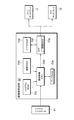
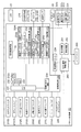
次に、図を参照しつつ、ゲームマシン10の内部構成について説明する。図6は内部の構成を中心に示すゲームマシン10のブロック図である。ゲームマシン10は、マイクロコンピュータ41を中心に複数の構成要素を有している。   Next, the internal configuration of the game machine 10 will be described with reference to the drawings. FIG. 6 is a block diagram of the game machine 10 mainly showing the internal configuration. The game machine 10 has a plurality of components centering on the microcomputer 41.

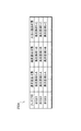
マイクロコンピュータ41は、メインCPU(Central Processing Unit)42と、RAM(Random Access Memory)43と、ROM(Read Only Memory)44とを有している。メインCPU42は、ROM44に記憶されているプログラムにしたがって作動し、I/Oポート49を介して、操作パネル14に設けられた各構成要素から信号を入力する一方、他の構成要素との信号の入出力を行い、ゲームマシン10全体の動作制御を行う。RAM43はメインCPU42が作動する際に用いるデータやプログラム(本実施の形態では、後述するアプリケーションデータ)が記憶される。ROM44には、メインCPU42が実行する制御プログラム及び図7に示すような発光態様データベース44aが記憶されており、その他にも恒久的な各種データが記憶されている。   The microcomputer 41 has a main CPU (Central Processing Unit) 42, a RAM (Random Access Memory) 43, and a ROM (Read Only Memory) 44. The main CPU 42 operates in accordance with a program stored in the ROM 44, and inputs signals from each component provided on the operation panel 14 via the I / O port 49, while receiving signals from other components. Input / output is performed to control the operation of the entire game machine 10. The RAM 43 stores data and programs (application data described later in the present embodiment) used when the main CPU 42 operates. The ROM 44 stores a control program executed by the main CPU 42 and a light emission mode database 44a as shown in FIG. 7, and also stores various permanent data.

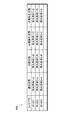
この発光態様データベース44aは、より具体的には、上述したフィギア30のICチップ34それぞれに記憶されているフィギア記憶情報のフィギアIDと、迷宮対戦ゲームにおける各遊技状態(図7では、通常状態、対戦状態、対戦勝利状態と対戦敗北状態の2種類の状態を示している。)における発光態様とが、互いに関連づけられて格納されている。この発光態様データベース44aに格納されている各発光態様は、上述したフィギア設置ユニット15のLED21の発光態様を決定するための情報であり、発光させる発光素子の種類、点灯タイミング、発光強度等の要素によって規定されている。例えば、フィギアID「B1001」の「通常状態」に対応する「発光態様1−A」ではLED21の青色発光素子が点灯する発光態様を示す情報、「対戦状態」に対応する「発光態様1−B」ではLED21の赤色発光素子が点灯する発光態様を示す情報、「対戦勝利状態」に対応する「発光態様1−C」では、LED21の赤色発光素子と青色発光素子とが0.5秒周期で交互に点灯する発光態様を示す情報となっており、「対戦敗北状態」に対応する「発光態様1−D」では、LED21の全ての発光素子が1秒間隔で10秒間点滅する発光態様を示す情報となっている。   More specifically, the light emission mode database 44a includes the figure ID of the figure storage information stored in each of the IC chips 34 of the figure 30 described above, and each gaming state in the labyrinth battle game (in FIG. 7, the normal state, Two types of states, that is, a battle state, a battle victory state, and a battle defeat state are shown.) Are stored in association with each other. Each light emission mode stored in the light emission mode database 44a is information for determining the light emission mode of the LED 21 of the figure installation unit 15 described above, and includes factors such as the type of light emitting element to emit light, lighting timing, and light emission intensity. It is prescribed by. For example, in “light emission mode 1-A” corresponding to the “normal state” of the figure ID “B1001”, information indicating a light emission mode in which the blue light emitting element of the LED 21 is lit, “light emission mode 1-B” corresponding to “competition state” "Indicates the light emission mode that the red light emitting element of the LED 21 is lit. In" Light emission mode 1-C "corresponding to" Battle victory state ", the red light emitting element and the blue light emitting element of the LED 21 are cycled at 0.5 second intervals. It is information indicating the light emission mode that is alternately turned on, and “light emission mode 1-D” corresponding to “competitive defeat state” indicates a light emission mode in which all the light emitting elements of the LED 21 blink for 10 seconds at intervals of 1 second. It is information.

また、ゲームマシン10は、乱数発生器45と、サンプリング回路46と、クロックパルス発生回路47と、分周器48とを有している。乱数発生器45は、メインCPU42の指示にしたがい作動して、一定範囲の乱数を発生させる。サンプリング回路46は、メインCPU42の指示にしたがい、乱数発生器45が発生させた乱数の中から任意の乱数を抽出し、その抽出した乱数をメインCPU42に入力する。クロックパルス発生回路47は、メインCPU42を作動させるための基準クロックを発生させ、分周器48はその基準クロックを一定周期で分周した信号をメインCPU42に入力する。   The game machine 10 also includes a random number generator 45, a sampling circuit 46, a clock pulse generation circuit 47, and a frequency divider 48. The random number generator 45 operates in accordance with an instruction from the main CPU 42 and generates a certain range of random numbers. The sampling circuit 46 extracts an arbitrary random number from the random numbers generated by the random number generator 45 in accordance with an instruction from the main CPU 42 and inputs the extracted random number to the main CPU 42. The clock pulse generation circuit 47 generates a reference clock for operating the main CPU 42, and the frequency divider 48 inputs a signal obtained by dividing the reference clock at a constant period to the main CPU 42.

さらに、ゲームマシン10のI/Oポート49には、タッチパネル11a、コインセンサ16a、カードリーダ18a、発光制御回路50、フィギア設置ユニット15、通信制御部51及び通信処理部(通信手段)52が接続されており、さらに、画像制御回路53及び音制御回路54が接続されている。   Further, the touch panel 11a, the coin sensor 16a, the card reader 18a, the light emission control circuit 50, the figure installation unit 15, the communication control unit 51, and the communication processing unit (communication means) 52 are connected to the I / O port 49 of the game machine 10. In addition, an image control circuit 53 and a sound control circuit 54 are connected.

タッチパネル11aは、メインディスプレイ11の表示画面を覆うように設けられていて、遊技者の指が触れた箇所の位置を検出し、その検出した位置に対応した位置信号をメインCPU42に入力する。遊技者はこのタッチパネル11aを用いてキャラクタの動作を決めるための操作入力を行う。例えば、タッチパネル11aは、長方形の透明板表面に導電物質を塗布しており、その透明板の四角に配置された電極から電圧をかけ、遊技者の指が触れることによる微弱な電流変化を電極で検知して、遊技者の指が触れた箇所の位置を検出する。なお、本実施形態における操作手段は、このタッチパネル11aと操作ユニット19とで構成されている。   The touch panel 11 a is provided so as to cover the display screen of the main display 11, detects the position of the part touched by the player's finger, and inputs a position signal corresponding to the detected position to the main CPU 42. The player uses the touch panel 11a to input an operation for determining the character's movement. For example, in the touch panel 11a, a conductive material is applied to the surface of a rectangular transparent plate, a voltage is applied from the electrodes arranged on the squares of the transparent plate, and a slight current change caused by touching a player's finger is applied to the electrodes. Detect and detect the position of the part touched by the player's finger. The operation means in this embodiment is composed of the touch panel 11a and the operation unit 19.

コインセンサ16aは、コイン投入口16から投入されたコインを検出し、その検出に対応する検出信号をメインCPU42に出力する。カードリーダ18aは、カードスロット18に挿入されたIDカード17に記録されている遊技者ID等のカード情報を読み取り、その読み取ったカード情報をメインCPU42に入力する。   The coin sensor 16a detects a coin inserted from the coin insertion slot 16, and outputs a detection signal corresponding to the detection to the main CPU. The card reader 18a reads card information such as a player ID recorded on the ID card 17 inserted in the card slot 18, and inputs the read card information to the main CPU.

発光制御回路50は、メインCPU42からの指示に従い、フィギア設置ユニット15のLED21の各発光素子(赤色発光素子、青色発光素子、緑色発光素子)に対して発光信号を出力する。すなわち、発光制御回路50によって、LED21は様々の発光態様での発光演出を実現することができるようになっている。   The light emission control circuit 50 outputs a light emission signal to each light emitting element (red light emitting element, blue light emitting element, green light emitting element) of the LED 21 of the figure installation unit 15 in accordance with an instruction from the main CPU 42. That is, the light emission control circuit 50 enables the LED 21 to realize light emission effects in various light emission modes.

フィギア設置ユニット15は、ICチップリーダライタ20とLED21とを備えている。そして、ICチップリーダライタ20は、必要に応じて、フィギア30のICチップ34からフィギア記憶情報を読み取ってメインCPU42に入力し、メインCPU42からの情報をICチップ34に書き込んでフィギア記憶情報を更新する。また、LED21は、上述した発光制御回路50によってその発光が制御される。   The figure installation unit 15 includes an IC chip reader / writer 20 and an LED 21. Then, the IC chip reader / writer 20 reads the figure storage information from the IC chip 34 of the figure 30 and inputs it to the main CPU 42 as necessary, and writes the information from the main CPU 42 into the IC chip 34 to update the figure storage information. To do. The light emission of the LED 21 is controlled by the light emission control circuit 50 described above.

通信制御部51は、メインCPU42の指示にしたがい作動して、店舗サーバ2と通信を行うための回線の接続および切断を制御する。通信処理部52は通信制御部51の指示にしたがい作動して、専用回線Cを介して行われるデータの送受信を実行する。 The communication control unit 51 operates according to an instruction from the main CPU 42 and controls connection and disconnection of a line for communicating with the store server 2. The communication processing unit 52 operates according to an instruction of the communication control unit 51 performs transmission and reception of data performed via a dedicated line C 1.

画像制御回路71は、メインディスプレイ11、サブディスプレイ12のそれぞれにおける画像表示を制御して、キャラクタを示す画像等の各種の画像をメインディスプレイ11、サブディスプレイ12に表示させる。   The image control circuit 71 controls image display on each of the main display 11 and the sub display 12 to display various images such as an image showing a character on the main display 11 and the sub display 12.

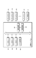
この画像制御回路53は、図8に示すように、画像制御CPU53a、ワークRAM53b、プログラムROM53c、画像ROM53d、ビデオRAM53eおよびVDP(Video Display Processor)53fを有している。画像制御CPU53aは、マイクロコンピュータ41で設定されたパラメータに基づき、プログラムROM53cに予め記憶されている(メインディスプレイ11、サブディスプレイ12での表示に関する)画像制御プログラムに従い、メインディスプレイ11、サブディスプレイ12に表示される画像を決定する。ワークRAM53bは、画像制御CPU53aが画像制御プログラムを実行するときの一時記憶手段として構成されている。   As shown in FIG. 8, the image control circuit 53 includes an image control CPU 53a, a work RAM 53b, a program ROM 53c, an image ROM 53d, a video RAM 53e, and a VDP (Video Display Processor) 53f. Based on the parameters set by the microcomputer 41, the image control CPU 53a follows the image control program (related to the display on the main display 11 and the sub display 12) stored in advance in the program ROM 53c. Determine the image to be displayed. The work RAM 53b is configured as a temporary storage unit when the image control CPU 53a executes the image control program.

プログラムROM53cは、画像制御プログラムや各種選択テーブルなどを記憶している。画像ROM53dは、画像を形成するためのドットデータを記憶している。ビデオRAM53eは、VDP53fにより画像を形成するときの一時記憶手段として構成されている。VDP53fは制御RAM53gを有し、画像制御CPU53aで決定されたメインディスプレイ11、サブディスプレイ12の表示内容に応じた画像を形成し、その形成された各画像をメインディスプレイ11、サブディスプレイ12に出力する。   The program ROM 53c stores an image control program, various selection tables, and the like. The image ROM 53d stores dot data for forming an image. The video RAM 53e is configured as a temporary storage unit when an image is formed by the VDP 53f. The VDP 53f has a control RAM 53g, forms images according to the display contents of the main display 11 and the sub display 12 determined by the image control CPU 53a, and outputs the formed images to the main display 11 and the sub display 12. .

音制御回路54はスピーカ13L、13Rから音声を出力するための音声信号をスピーカ13L、13Rに入力する。スピーカ13L、13Rからは、例えば、ゲーム開始後、適当な時期にゲームを盛り上げるための音声が出力される。
(店舗サーバ、カード販売機、店舗内ルータの構成)
The sound control circuit 54 inputs sound signals for outputting sound from the speakers 13L and 13R to the speakers 13L and 13R. From the speakers 13L and 13R, for example, a sound for exciting the game is output at an appropriate time after the game is started.
(Configuration of store server, card vending machine, in-store router)

店舗サーバ2は、図9に示すように、CPU61、ROM62、RAM63、通信処理部64、通信制御部65およびアプリケーションデータを記憶しているデータ記憶部66を有している。そして、CPU61がROM62に記憶されているプログラムにしたがいRAM63にデータを読み書きしながら作動し、一方、通信制御部65がCPU61の指示にしたがい通信処理部64を作動させる。そして、店舗サーバ2は、各遊技店舗A,Bに設置されている各ゲームマシン10と専用回線Cを介してデータの送受信を行い、各ゲームマシン10へのアプリケーションデータの送信(ダウンロード)や、各ゲームマシン10同士およびセンターサーバ群5とにおけるデータ送受信の中継を行う。アプリケーションデータは、ゲームマシン10で行われる迷宮対戦ゲームの実行に用いられる各種データ(ゲーム用の画像データ)と、ボード用データ(操作ユニット19に備えられている操作ボタンを迷宮対戦ゲームに対応させる設定用のプログラム)が含まれている。 As shown in FIG. 9, the store server 2 includes a CPU 61, a ROM 62, a RAM 63, a communication processing unit 64, a communication control unit 65, and a data storage unit 66 that stores application data. Then, the CPU 61 operates while reading / writing data from / to the RAM 63 according to the program stored in the ROM 62, while the communication control unit 65 operates the communication processing unit 64 according to the instruction of the CPU 61. The store server 2 transmits / receives data to / from each game machine 10 via the dedicated line C 1 with each game machine 10 installed in each game store A, B, and transmits (downloads) application data to each game machine 10. The data transmission / reception relay between the game machines 10 and the center server group 5 is performed. As application data, various data (game image data) used for execution of a labyrinth battle game performed on the game machine 10 and board data (operation buttons provided in the operation unit 19) are associated with the labyrinth battle game. Configuration program).

カード販売機3は、遊技者が個人情報の入力操作を行う操作部と、カード発行手段とを有し、その操作部を用いた所定の入力操作によって、カード発行手段が各遊技者固有の遊技者IDを含むカード情報を記憶させてIDカード17を発行する。   The card vending machine 3 has an operation unit for a player to input personal information and a card issuing unit, and the card issuing unit performs a game unique to each player by a predetermined input operation using the operation unit. The card information including the person ID is stored and the ID card 17 is issued.

店舗内ルータ4は、各遊技店舗A,Bに形成されている店舗内LANと、通信回線CおよびインターネットNTを介してセンターサーバ群5に形成されているLANとを接続している。
(センターサーバ群の構成)
Store router 4 is connected with store LAN formed in each game shops A, B, and a LAN that is formed in the center server group 5 via the communication line C 2 and the Internet NT.
(Configuration of center server group)

センターサーバ群5は、ゲームごとに対応して設置された複数のゲームサーバ(図1では、2台のゲームサーバ6A、6B)と、データベースサーバ7とを有し、各ゲームサーバが専用回線Cを介して接続されてLANを形成し、そのLANが図示しないルータを介してインターネットNTに接続されている。 The center server group 5 has a plurality of game servers (two game servers 6A and 6B in FIG. 1) and a database server 7 installed corresponding to each game, and each game server has a dedicated line C. 3 is connected to form a LAN, and the LAN is connected to the Internet NT via a router (not shown).

ゲームサーバ6Aは、迷宮対戦ゲームを実行するために設置されていて、図10に示すように、CPU71、ROM72、RAM73、通信処理部74、通信制御部75およびデータ記憶部76を有している。そして、ゲームサーバ6Aでは、CPU71がROM72に記憶されているプログラムにしたがいRAM73にデータを読み書きしながら作動し、一方、通信制御部75がCPU71の指示にしたがい通信処理部74を作動させる。   The game server 6A is installed to execute a labyrinth battle game, and includes a CPU 71, a ROM 72, a RAM 73, a communication processing unit 74, a communication control unit 75, and a data storage unit 76 as shown in FIG. . In the game server 6A, the CPU 71 operates while reading / writing data from / to the RAM 73 according to a program stored in the ROM 72, while the communication control unit 75 operates the communication processing unit 74 according to an instruction from the CPU 71.

ゲームサーバ6Aは、各店舗サーバ2とインターネットNTを介してデータの送受信を行う。そして、各ゲームマシン10から送信される後述するエントリーデータを受信して遊技者の迷宮対戦ゲームへの参加(エントリー)受付および遊技者の参加情報の更新を行い、対戦相手となる遊技者を決定し、その結果をデータベースサーバ7に送信する。   The game server 6A transmits / receives data to / from each store server 2 via the Internet NT. Then, entry data, which will be described later, transmitted from each game machine 10 is received, and the player's participation (entry) reception in the labyrinth battle game is received and the player's participation information is updated, and the player who becomes the opponent is determined. The result is transmitted to the database server 7.

ゲームサーバ6Bは、ゲームサーバ6Aが提供するゲームとは異なるゲームを実行するために設置されたもので、ゲームサーバ6Aとは記憶しているデータやプログラムが違っている点で異なるが、そのシステム構成自体は同様又は同等のものである。   The game server 6B is installed to execute a game different from the game provided by the game server 6A. The game server 6B is different from the game server 6A in that the stored data and programs are different. The configuration itself is similar or equivalent.

データベースサーバ7は、CPU81、ROM82、RAM83、通信処理部84、通信制御部85およびデータ記憶部86を有している。そして、データベースサーバ7では、CPU81がROM82に記憶されているプログラムにしたがいRAM83にデータを読み書きしながら作動し、一方、通信制御部85がCPU81の指示にしたがい通信処理部84を作動させ、各店舗サーバ2とインターネットNTを介してデータの送受信を行う。データ記憶部86には遊技者ID、遊技者の認証に用いられるパスワード、ゲームの種別およびゲームデータが記憶されている。遊技者IDは、ゲームマシン10により、IDカード17から読み取って送信されたものである。   The database server 7 includes a CPU 81, a ROM 82, a RAM 83, a communication processing unit 84, a communication control unit 85, and a data storage unit 86. In the database server 7, the CPU 81 operates while reading / writing data from / to the RAM 83 according to the program stored in the ROM 82, while the communication control unit 85 operates the communication processing unit 84 according to the instruction of the CPU 81, Data is transmitted and received through the server 2 and the Internet NT. The data storage unit 86 stores a player ID, a password used for player authentication, a game type, and game data. The player ID is read from the ID card 17 by the game machine 10 and transmitted.

また、前述したとおり、各遊技者がゲームマシン10において、自己の使用するフィギア30をフィギア設置ユニット15にセットし、フィギア記憶情報のフィギアIDを読み取らせたことによって、データベースサーバ7にはその読み取らせたフィギア30に対応するフィギアIDがゲームマシン10から送信されるようになっている。データベースサーバ7は、ゲームマシン10から送信される1つの遊技者IDに対して、対応する複数のフィギアIDを関連付けて記憶可能なID管理ファイルがデータ記憶部86に形成されている。このID管理ファイルによって、遊技者およびその遊技者が使用するフィギアを管理するようにしている。このID管理ファイルは後述する遊技者の認証およびフィギアの認証で用いられる。   Further, as described above, each player sets the figure 30 used by the player in the game machine 10 in the figure installation unit 15 and reads the figure ID of the figure storage information, so that the database server 7 reads the figure ID. The figure ID corresponding to the set figure 30 is transmitted from the game machine 10. In the database server 7, an ID management file capable of storing a plurality of corresponding figure IDs in association with one player ID transmitted from the game machine 10 is formed in the data storage unit 86. This ID management file manages the player and the figure used by the player. This ID management file is used for player authentication and figure authentication described later.

ゲームデータは、迷宮対戦ゲームに登場する複数のキャラクタについて、各キャラクタを特徴づけるキャラクタ固有のデータ(各キャラクタのコスチューム、コスチュームカラーや、防御パラメータ、攻撃パラメータおよび攻撃範囲を含むキャラクタ能力値、特殊能力などを示す情報、以下「フィギア情報」という)と、各遊技者による迷宮対戦ゲームの履歴を示すデータが含まれている。このゲームデータは、データベースサーバ7からゲームマシン10に送信され、迷宮対戦ゲームで用いられる。
(ゲームマシンの動作内容)
The game data is the character-specific data that characterizes each character of multiple characters appearing in the labyrinth battle game (characters including costumes, costume colors, defense parameters, attack parameters, attack ranges, and special abilities for each character) Etc., hereinafter referred to as “figure information”), and data indicating the history of the labyrinth battle game by each player. This game data is transmitted from the database server 7 to the game machine 10 and used in the labyrinth battle game.
(Game machine operation details)

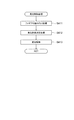
次に、以上の構成を有するゲームマシン10の動作内容について、図11〜図14に示すフローチャートを参照して説明する。なお、以下の説明では、遊技店舗Aに設置されている8台のゲームマシン10のうちの4台のゲームマシン10を、それぞれの遊技者が操作して同じ迷宮対戦ゲームを行う場合を例にとって説明する。   Next, the operation content of the game machine 10 having the above configuration will be described with reference to the flowcharts shown in FIGS. In the following description, a case where four players out of the eight game machines 10 installed in the game store A are operated by the respective players to play the same labyrinth battle game is taken as an example. explain.

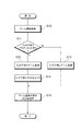
図11は各ゲームマシン10におけるゲームの開始から終了までのゲーム処理の動作手順を示すフローチャートである。なお、図11および後述する図12〜図14ではステップをSと略記している。以下の説明では、4人の遊技者が操作するうちの1台のゲームマシン10を例にとって説明している。   FIG. 11 is a flowchart showing the operation procedure of the game process from the start to the end of the game in each game machine 10. Note that step is abbreviated as S in FIG. 11 and FIGS. In the following description, one game machine 10 out of four gamers will be described as an example.

ゲームマシン10は電源投入時に店舗サーバ2に対してアプリケーションデータのダウンロード要求を送信し(後述するステップ100)、一方、店舗サーバ2がダウンロード要求を受信すると、ダウンロード要求を送信してきたゲームマシン10にアプリケーションデータを送信する(図14参照)。   When the game machine 10 is turned on, it sends a download request for application data to the store server 2 (step 100 to be described later). On the other hand, when the store server 2 receives the download request, it sends the download request to the game machine 10 that has sent the download request. Application data is transmitted (see FIG. 14).

ゲームマシン10は、アプリケーションデータを受信すると、そのアプリケーションデータをRAM43に記憶させる。そして、ゲームマシン10では、メインCPU42がアプリケーションデータを読み込むと、遊技者の操作入力に応じて迷宮対戦ゲームを進行させる。このとき、各ゲームマシン10のメインCPU42は、店舗サーバ2およびセンターサーバ群5を介して互いに同期をとりながら、メインディスプレイ11に遊技画像を表示するようになっている。   When the game machine 10 receives the application data, the game machine 10 stores the application data in the RAM 43. In the game machine 10, when the main CPU 42 reads the application data, the labyrinth battle game is advanced according to the operation input of the player. At this time, the main CPU 42 of each game machine 10 displays a game image on the main display 11 while synchronizing with each other via the store server 2 and the center server group 5.

このとき、各ゲームマシン10は、ゲーム処理を開始すると、ステップ10に進んでコイン投入、IDカードの挿入、キャラクタ生成処理を含む後述のゲーム開始処理を行う。ステップ11では、ゲーム開始処理の結果から、フィギア有りフラグに所定のデータがセットされている(セット有り)か否かを判定し、その判定結果に応じてステップ12,13に処理を分岐させて(フィギア有りフラグのセット有りのときはステップ12、そうでないときはステップ13)、いずれかの処理を行いステップ12に続くステップ14でフィギア有りフラグをクリアした上でステップ15に進み、対戦成績などのゲーム結果の表示を行う一方、データベースサーバ7において、ゲームデータを更新させるため、対戦成績を示すデータを店舗サーバ2を経由してデータベースサーバ7に送信する後処理を行い、処理を終了する。   At this time, when the game process is started, each game machine 10 proceeds to step 10 and performs a game start process described later including coin insertion, ID card insertion, and character generation process. In step 11, it is determined whether or not predetermined data is set in the figure present flag (set present) from the result of the game start process, and the process branches to steps 12 and 13 according to the determination result. (If the figure present flag is set, step 12; otherwise, step 13). If any figure is processed and the figure present flag is cleared in step 14 following step 12, the process proceeds to step 15, and the competition results, etc. On the other hand, in order to update the game data in the database server 7, post-processing is performed to transmit the data indicating the competition results to the database server 7 via the store server 2, and the processing ends.

このように、ゲームマシン10では、フィギア有り、フィギア無しいずれのモードでも迷宮対戦ゲームを行えるようになっている。ただし、フィギア有りモードでは、フィギア無しモードよりもゲーム内容が遊技者にとって有益になるようになっている
(ゲーム開始処理)
As described above, the game machine 10 can play the labyrinth battle game in any mode with or without the figure. However, in the mode with the figure, the game content is more beneficial to the player than in the mode without the figure (game start processing).

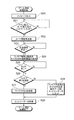
ステップ1のゲーム開始処理は図12に示すフローチャートに沿って行われる。図12はゲーム開始処理の動作手順を示すフローチャート、図13はキャラクタ生成処理の動作手順を示すフローチャートである。   The game start process of step 1 is performed according to the flowchart shown in FIG. FIG. 12 is a flowchart showing the operation procedure of the game start process, and FIG. 13 is a flowchart showing the operation procedure of the character generation process.

メインCPU42はゲーム開始処理を開始するとステップ20に進み、メッセージ出力処理を行い、画像制御回路53に指示してメインディスプレイ11に所定のメッセージ(コイン投入要求、IDカードの挿入要求およびパスワードの入力要求)を表示させる。続いて、ステップ21,22と処理を実行する。   When the main CPU 42 starts the game start process, the main CPU 42 proceeds to step 20, performs a message output process, instructs the image control circuit 53, and sends a predetermined message (coin insertion request, ID card insertion request, and password input request) to the main display 11. ) Is displayed. Subsequently, steps 21 and 22 are executed.

遊技者は、ゲームを開始するためには、コインをコイン投入口16から投入するとともに、IDカード17をカードスロット18に挿入し、操作ユニット19を用いてパスワードを入力する。すると、投入されたコインの検出信号がコインセンサ16aからメインCPU42に入力され、カードリーダ18aからはIDカード17に記憶されているカード情報が入力される。さらに、操作ユニット19からパスワードが入力され、これらすべての入力があるとステップ22に進み、メインCPU42が通信制御部51に指示して通信処理部52を作動させ、読み取ったカード情報および入力されたパスワードを店舗サーバ2に送信する。   In order to start the game, the player inserts a coin from the coin insertion slot 16, inserts the ID card 17 into the card slot 18, and inputs a password using the operation unit 19. Then, a detection signal of the inserted coin is input from the coin sensor 16a to the main CPU 42, and card information stored in the ID card 17 is input from the card reader 18a. Further, when the password is input from the operation unit 19 and all these inputs are made, the process proceeds to step 22 where the main CPU 42 instructs the communication control unit 51 to operate the communication processing unit 52 and the read card information and the input are made. The password is transmitted to the store server 2.

そして、続くステップ23で店舗サーバ2からの応答信号を受信するまで待機し、応答信号を受信すると、フィギアの有り、無しと、応答信号から認証(登録)済みか否かを区別して、選択可能な各種キャラクタのいずれかを選択させる選択画面の表示をメインディスプレイ11で行うための指示を次のステップ24で行い、続くステップ25では、タッチパネル11aのタッチがあるまで待機して、タッチがあるとステップ26に進み、ステップ24でフィギア有りを選択したか否かを判定する。ここで、フィギア有りを選択した場合はステップ27に進み、そうでなければステップ28に進む。ステップ27に進むと、後述するキャラクタ生成処理を行い、ステップ28ではフィギア不使用によるキャラクタ生成指示(ノンフィギアのキャラクタ生成指示)データを後述するエントリーデータにセットし、いずれも後続のステップ29に進む。詳しくは、ステップ26では、初めてフィギアを用いるときおよび既に認証済みのフィギアがあり、その認証済みのフィギアとは別のフィギアを用いるときのいずれにおいても、遊技者によってフィギア有りが選択されると、ステップ27に進み、キャラクタ生成処理が行われる。また、初めからフィギアを用いないときおよび既に認証済みのフィギアがあるのにそのフィギアを用いないときは、遊技者によってフィギア無しが選択されると、ステップ28に進む。   In step 23, the process waits until the response signal from the store server 2 is received. When the response signal is received, the presence / absence of the figure can be distinguished from the response signal to select whether it has been authenticated (registered) or not. In order to display the selection screen for selecting any of various characters on the main display 11, an instruction is given in the next step 24. In the following step 25, the touch panel 11a is waited until touched. Proceeding to step 26, it is determined whether or not the figure is selected at step 24. If the figure is selected, the process proceeds to step 27, and if not, the process proceeds to step 28. In step 27, a character generation process to be described later is performed. In step 28, character generation instruction (non-figure character generation instruction) data by non-use of the figure is set in entry data to be described later, and both proceed to the subsequent step 29. . Specifically, in step 26, when the figure is used for the first time and there is an already certified figure, and when a figure different from the certified figure is used, the player selects that the figure is present. Proceeding to step 27, character generation processing is performed. Further, when the figure is not used from the beginning and when there is an already authenticated figure and the figure is not used, the process proceeds to step 28 when the player selects no figure.

そして、ステップ27に進むと、メインCPU42は図13に示すフローチャートに沿ってキャラクタ生成処理を行う。この処理を開始すると、ステップ30に進み、フィギアのセット要求メッセージ出力処理を行う。ここでは、メインCPU42が画像制御回路53に指示してメインディスプレイ11に、フィギア30をフィギア設置ユニット15に装着し、フィギアIDを読取るセッティングを要求するメッセージ(例えば、“フィギアの台座を操作パネル上のフィギア設置ユニットにセットしてください。フィギアの認証が始まると、フィギア設置ユニットが明るく点灯しますので、明かりが消えるまでフィギアをはずさないで下さい”)を表示させ、続くステップ31では、フィギアIDの読み取りが終わるまで待機する。遊技者が表示されるメッセージにしたがいフィギア30をフィギア設置ユニット15にセットすると、フィギア設置ユニット15がフィギア30のICチップ34に記憶されているフィギアIDを読み取り、メインCPU42に入力する。すると、ステップ32に進み、メインCPU42が読み取ったフィギアIDを含むキャラクタ生成指示データをエントリーデータにセットし、続くステップ33では、フィギア30のフィギアIDの読取(フィギアのセッティング)が行われたことを示すフィギア有りフラグに所定のデータ(本実施の形態では“1”)をセットし、このステップ33を実行すると、キャラクタ生成処理が終了する。   In step 27, the main CPU 42 performs character generation processing according to the flowchart shown in FIG. When this process is started, the process proceeds to step 30 to perform a figure set request message output process. Here, the main CPU 42 instructs the image control circuit 53 to attach the figure 30 to the figure installation unit 15 on the main display 11 and to request a setting for reading the figure ID (for example, “Figure pedestal on the operation panel When the figure certification starts, the figure installation unit will light up brightly, so do not remove the figure until the light goes off. ”) Is displayed. Wait until reading is complete. When the figure 30 is set in the figure installation unit 15 in accordance with the message displayed by the player, the figure installation unit 15 reads the figure ID stored in the IC chip 34 of the figure 30 and inputs it to the main CPU 42. In step 32, the character generation instruction data including the figure ID read by the main CPU 42 is set in the entry data. In the next step 33, the figure ID of the figure 30 is read (figure setting). When predetermined data ("1" in the present embodiment) is set in the figure flag shown, and this step 33 is executed, the character generation process ends.

このように、ゲームマシン10は、フィギアのセッティングが行われたときにフィギア有りフラグに所定のデータをセットするようにしている。一旦、フィギアのセッティングを行うと、キャラクタ生成指示データを含むエントリーデータが店舗サーバ2を介してデータベースサーバ7に送信され、データベースサーバ7においてそのフィギアIDがそのセッティングを行った遊技者固有の遊技者IDに関連付けてID管理ファイルに記憶され、そのフィギアを認証済か否かの判断に用いられる。また、ID管理ファイルによるフィギアの認証済か否かの判定結果が応答信号として、データベースサーバ7から送信されるので、遊技者は認証済みのフィギアに対応するキャラクタを選択して迷宮対戦ゲームを行える。ただし、フィギアのセッティングを行わないと、フィギア有りフラグのセットが行われないので、たとえフィギアの認証済みでも、迷宮対戦ゲームをフィギア有りモードで行うには、フィギア30をフィギア設置ユニット15にセットしてフィギアIDの読取を行う必要がある。そして、セッティングを行うと、読み取ったフィギアIDに対応するフィギア情報がデータベースサーバ7で生成され、フィギア30のセッティングを繰返し行わなくても迷宮対戦ゲームを行えるようになっている。   As described above, the game machine 10 sets predetermined data in the figure presence flag when the figure is set. Once the figure is set, the entry data including the character generation instruction data is transmitted to the database server 7 via the store server 2, and the player ID unique to the player who has set the figure ID in the database server 7. It is stored in the ID management file in association with the ID, and is used to determine whether or not the figure has been authenticated. Further, the determination result of whether or not the figure is authenticated by the ID management file is transmitted from the database server 7 as a response signal, so that the player can select a character corresponding to the authenticated figure and play the labyrinth battle game. . However, if the figure is not set, the figure flag is not set. Therefore, even if the figure is already authenticated, the figure 30 is set in the figure installation unit 15 in order to play the labyrinth battle game in the figure equipped mode. Therefore, it is necessary to read the figure ID. When the setting is performed, the figure information corresponding to the read figure ID is generated by the database server 7, and the labyrinth battle game can be played without repeating the setting of the figure 30.

なお、ゲーム開始処理のステップ27に進むと、メインCPU42が通信制御部51に指示して通信処理部52を作動させ、エントリーデータを店舗サーバ2に送信する。このステップ27が終了すると、ゲーム開始処理が終了する。   When the process proceeds to step 27 of the game start process, the main CPU 42 instructs the communication control unit 51 to operate the communication processing unit 52 and transmits entry data to the store server 2. When this step 27 ends, the game start process ends.

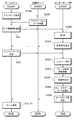
一方、ゲームマシン10、店舗サーバ2およびセンターサーバ群5では、上述の処理に対応して、図14に示す順序で処理が実行されている。図14は、ゲームマシン10、店舗サーバ2およびセンターサーバ群5の間で行われる動作シーケンスを示すシーケンスチャートである。   On the other hand, in the game machine 10, the store server 2, and the center server group 5, processing is executed in the order shown in FIG. 14 corresponding to the above-described processing. FIG. 14 is a sequence chart showing an operation sequence performed between the game machine 10, the store server 2, and the center server group 5.

ゲームマシン10では、ステップ100において、店舗サーバ2にダウンロード要求を送信してアプリケーションデータをダウンロードし、上述のとおりステップ22でカード情報等を送信する。すると、センターサーバ群5では、ステップ300に進んで、データベースサーバ7におけるCPU81がゲームマシン10から送信されたカード情報およびパスワードを用いて、ID管理ファイルを参照するなどして遊技者およびフィギアが登録されているか否かを判断する認証処理を行い、登録済の場合は認証済としてステップ301に進み、その認証結果を示す応答信号をゲームマシン10に送信する。この場合、データベースサーバ7では、各店舗A,Bに8台ずつ設置されているゲームマシン10に対して、同様の認証処理を行う。   In the game machine 10, in step 100, a download request is transmitted to the store server 2 to download application data, and card information and the like are transmitted in step 22 as described above. Then, in the center server group 5, the process proceeds to step 300, where the CPU 81 in the database server 7 refers to the ID management file using the card information and password transmitted from the game machine 10, and the player and the figure are registered. An authentication process is performed to determine whether or not it has been registered. If it has been registered, the process proceeds to step 301 as being authenticated, and a response signal indicating the authentication result is transmitted to the game machine 10. In this case, the database server 7 performs the same authentication process for eight game machines 10 installed in each store A and B.

また、ゲームマシン10では、上述のステップ29に示したエントリーデータの送信を行う。すると、センターサーバ群5では、ステップ302に進んでゲームサーバ6Aにより、各ゲームマシン10からのエントリーデータを用いて、遊技者のエントリー受付を行う。さらに、後続のステップ303では遊技者の参加情報の更新およびキャラクタ生成指示データに対応するフィギアID(このフィギアIDには、認証されていない新規登録のフィギアと、認証済みで再度認証するフィギアの双方のフィギアIDが含まれる)を用いてID管理ファイルへのフィギアの登録または更新と、フィギア情報の生成または更新を行い、続くステップ304で対戦相手となる遊技者(本実施の形態では4名)を決定する。また、ステップ305では、データベースサーバ7が対戦相手になる各遊技者のゲームデータを抽出してステップ306に進み、抽出したゲームデータを店舗サーバ2に送信する。店舗サーバ2では、ゲームデータを受信すると、それを各ゲームマシン10に送信する。
(LEDの発光態様)
Further, the game machine 10 transmits the entry data shown in step 29 described above. Then, in the center server group 5, the process proceeds to step 302, and the game server 6A receives entry of the player using the entry data from each game machine 10. Further, in the subsequent step 303, the figure ID corresponding to the update of the player's participation information and the character generation instruction data (both the figure ID that has not been authenticated and the figure that has been authenticated and is re-authenticated). The figure is registered or updated in the ID management file and the figure information is generated or updated, and in step 304, the players who are opponents (four players in this embodiment) To decide. In step 305, the database server 7 extracts game data of each player who becomes an opponent, proceeds to step 306, and transmits the extracted game data to the store server 2. When the store server 2 receives the game data, it transmits it to each game machine 10.
(Light emission mode of LED)

以上で説明したフィギア有りゲーム処理(ステップ12)がおこなわれている間は、ステップ31で読み取ったフィギアIDに基づき、迷宮対戦ゲームの遊技状態に応じたLED発光が行われる。   While the figure-with-game process (step 12) described above is being performed, LED light emission corresponding to the gaming state of the labyrinth battle game is performed based on the figure ID read in step 31.

すなわち、フィギア有りゲーム処理の際には、メインCPU42は、迷宮対戦ゲーム(画像遊技)を進行させる遊技進行制御手段として作動し、随時、自機の遊技状態(通常状態、対戦状態等)と、センターサーバ群5や店舗サーバ2から通信処理部52を介して受信する遊技関連情報(対戦結果、対戦相手の情報等)と、ROM44に格納されている発光態様データベース44aとに基づいてLED21の発光態様を決定する発光態様決定手段として作動する。   That is, during the game process with the figure, the main CPU 42 operates as a game progress control means for proceeding with the labyrinth battle game (image game), and from time to time the game state (normal state, battle state, etc.) of its own machine, LED 21 emits light based on game-related information (competition result, opponent information, etc.) received from the center server group 5 or the store server 2 via the communication processing unit 52 and the light emission mode database 44 a stored in the ROM 44. It operates as a light emission mode determining means for determining the mode.

図7を参照しつつより具体的に説明すると、発光態様決定手段として作動するメインCPU42は、フィギアID「B1001」のフィギア30がフィギア設置ユニット15にセットされているときには、対戦状態ではないときにはLED21の発光態様を「発光態様1−A」に決定し、対戦状態のときには「発光態様1−B」に決定する。そして、その対戦結果に関する情報が店舗サーバ2から送られてくると、その情報に基づいて、メインCPU42は、対戦勝利状態である「発光態様1−C」若しくは対戦敗北状態である「発光態様1−D」に発光態様を決定する。   More specifically, referring to FIG. 7, the main CPU 42 that operates as the light emission mode determining means is configured to display the LED 21 when the figure 30 with the figure ID “B1001” is set in the figure installation unit 15 and not in the battle state. The light emission mode is determined as “light emission mode 1-A”, and when in the battle state, it is determined as “light emission mode 1-B”. And when the information regarding the battle result is sent from the store server 2, based on the information, the main CPU 42 "light emission mode 1-C" which is the battle victory state or "light emission mode 1" which is the battle defeat state. -D "determines the light emission mode.

このようにしてメインCPU42によって発光態様が決定されると、発光制御回路(発光制御手段)50が決定された発光態様に従ったLED21の発光制御をおこなう。   When the light emission mode is determined by the main CPU 42 in this way, the light emission control circuit (light emission control means) 50 performs light emission control of the LED 21 according to the determined light emission mode.

そして、LED21から発光態様に従った光が出射されると、出射された光はフィギア設置ユニット15の保持部材23の内部を透過し、図15に示すように、周壁面23aからフィギア30を下側から照らす。そのため、保持部材23の周壁面23aから照射された光の一部は、フィギア30のフィギア本体部32の入射部(例えば、フィギア本体部32の脚部分32a)にあたる。ここで、フィギア30のフィギア本体部32は、上述したように透光性を有する材料で構成されているため、フィギア30のフィギア本体部32の入射部32aにあたった光の一部は、その部分からフィギア本体部32の内部に入射され、適宜反射や屈折を繰り返しながらフィギア本体部32内を透過して、出射部(例えば、フィギア本体部32の胴部分32b)から出射される。   When the light according to the light emission mode is emitted from the LED 21, the emitted light passes through the inside of the holding member 23 of the figure installation unit 15, and moves down the figure 30 from the peripheral wall surface 23a as shown in FIG. Illuminate from the side. Therefore, a part of the light emitted from the peripheral wall surface 23 a of the holding member 23 corresponds to the incident portion of the figure main body portion 32 of the figure 30 (for example, the leg portion 32 a of the figure main body portion 32). Here, since the figure main body portion 32 of the figure 30 is made of a light-transmitting material as described above, a part of the light hitting the incident portion 32a of the figure main body portion 32 of the figure 30 is The light is incident on the inside of the figure main body 32 from the portion, is transmitted through the figure main body 32 while repeating reflection and refraction as appropriate, and is emitted from the emission portion (for example, the trunk portion 32b of the figure main body 32).

すると、フィギア本体部32表面における反射光に加えて、フィギア本体部32の出射部32bからの出射光により、遊技者に対して視認可能に配置されたフィギア30自体の色があたかも変化したかのような視覚的効果を遊技者に与えることができる。   Then, in addition to the reflected light on the surface of the figure main body part 32, whether the color of the figure 30 itself arranged so as to be visible to the player is changed by the emitted light from the emission part 32b of the figure main body part 32. Such visual effects can be given to the player.

以上で詳細に説明したように、ゲームマシン10においては、フィギア設置ユニット15のICチップリーダライタ20によってフィギア30の台座部31に含まれるICチップ34からフィギア記憶情報が読み取られると、メインCPU42が、そのフィギア記憶情報に含まれるフィギアIDと自機の遊技状態と通信処理部52を介して外部から受信した情報とに基づいてLED21の発光態様を発光態様データベース44aを基に決定すると共に、発光制御回路50が、メインCPU42によって決定された発光態様に従ってLED21の発光制御を行う。そして、このLED21からフィギア30のフィギア本体部32の入射部32aまで届いた光は、フィギア30のフィギア本体部32内を透過して出射部32bから外部に出射される。従って、このゲームマシン10においては、フィギア30のICチップ34に記憶されたフィギアIDに基づきLED21の発光態様を変化させると、フィギア30の出射部32bから出射される光が変化し、フィギア30の外観が変わって見える。すなわち、ゲームマシン10は、フィギア30の交換をすることなく、フィギア30の外観をを変えることができるため、遊技者の興趣が十分に保たれる。特に、発光体として複数色の光を投光可能なフルカラーLED21を採用したことで、より多様性に富んだ発光態様が実現されている。   As described in detail above, in the game machine 10, when the figure memory information is read from the IC chip 34 included in the pedestal 31 of the figure 30 by the IC chip reader / writer 20 of the figure installation unit 15, the main CPU 42 The light emission mode of the LED 21 is determined based on the light emission mode database 44a based on the figure ID included in the figure storage information, the game state of the own device, and the information received from the outside via the communication processing unit 52, and the light emission The control circuit 50 performs light emission control of the LED 21 in accordance with the light emission mode determined by the main CPU 42. Then, the light reaching from the LED 21 to the incident part 32a of the figure main body part 32 of the figure 30 is transmitted through the figure main body part 32 of the figure 30 and emitted from the emission part 32b to the outside. Therefore, in this game machine 10, when the light emission mode of the LED 21 is changed based on the figure ID stored in the IC chip 34 of the figure 30, the light emitted from the emission part 32 b of the figure 30 changes, and the figure 30 Appearance changes. That is, since the game machine 10 can change the appearance of the figure 30 without exchanging the figure 30, the player's interest is sufficiently maintained. In particular, the use of the full-color LED 21 capable of projecting a plurality of colors of light as the light emitter realizes a light emission mode with more diversity.

また、発光態様決定手段として作動するメインCPU42は、フィギア記憶情報に含まれるフィギアIDだけでなく通信処理部52によって受信された店舗サーバ2からの情報にも基づいてLED21の発光態様を決定するため、多様性に富んだ発光態様を実現することができ、それにより遊技者の興趣が保たれる。   Further, the main CPU 42 that operates as the light emission mode determining means determines the light emission mode of the LED 21 based not only on the figure ID included in the figure storage information but also on the information from the store server 2 received by the communication processing unit 52. Therefore, it is possible to realize a variety of light emission modes, thereby maintaining the interest of the player.

また、上述したフィギア30は遊技者各々が所有することを想定したものであるため、ゲームマシン10の数よりもフィギア30の数の方が格段に多くなるが、ゲームマシン10にLED21を取り付けることで、各フィギア30にLED21を設ける場合に比べて用意するLED21の数を減らすことができる。また、ゲームマシン10がフィギア30に入射する光の色を決定するため、フィギアID等のフィギア記憶情報に依存することなく、同一の遊技状態において同一の発光制御を容易に実現することができる。さらに、フィギア30は、LED21を内蔵する必要がないため、安価に作製することができる。   Further, since the figure 30 described above is assumed to be owned by each player, the number of the figure 30 is significantly larger than the number of the game machines 10, but the LED 21 is attached to the game machine 10. Thus, the number of LEDs 21 to be prepared can be reduced as compared with the case where the LEDs 21 are provided in each figure 30. Further, since the game machine 10 determines the color of the light incident on the figure 30, the same light emission control can be easily realized in the same gaming state without depending on the figure storage information such as the figure ID. Furthermore, since the figure 30 does not need to incorporate the LED 21, it can be manufactured at low cost.

なお、発光態様は、必ずしも上述した4種類の遊技状態の変化によってのみ変更させる必要はなく、例えば、レベルアップ時や特定アイテムの入手時、特定キャラクターの出現時など、種々の遊技状態において変更させることができる。また、上述した第1実施形態では、遊技情報としてフィギア記憶情報のフィギアIDを用いた態様を示したが、例えば、フィギア記憶情報として、ゲーム対戦履歴、能力値、成長度等をICチップ34に直接記憶させておき、これらの情報を遊技情報として利用してもよい。   Note that the light emission mode does not necessarily have to be changed only by the above-described four types of game state changes. For example, the light emission mode may be changed in various game states such as level up, acquisition of a specific item, or the appearance of a specific character. be able to. In the first embodiment described above, the figure using the figure ID of the figure storage information is shown as the game information. For example, as the figure storage information, the game match history, ability value, degree of growth, etc. are stored in the IC chip 34. The information may be stored directly and used as game information.

また、以上で説明した第1実施形態においては、フィギア設置ユニット15の下部に設けられた1個のフルカラーLED21からの出射光が、保持部材23を介してフィギア30の入射部32aに入射される態様を示したが、LED等の発光体の設置数や設置位置は、適宜変更可能である。   In the first embodiment described above, the emitted light from one full color LED 21 provided at the lower part of the figure installation unit 15 enters the incident part 32a of the figure 30 through the holding member 23. Although an aspect was shown, the number of installations and installation positions of light emitters, such as LED, can be changed suitably.

例えば、上述したフィギア設置ユニット15を、図16〜18に示すようなフィギア設置ユニット15Aに適宜変更することも可能である。   For example, the above-described figure installation unit 15 can be appropriately changed to a figure installation unit 15A as shown in FIGS.

このフィギア設置ユニット15Aは、主に、背面透過パネル90を有する点、背面プレート91を有する点、背面透過パネル90と背面プレート91との間にLED支持板92が配置されている点で、上述したフィギア設置ユニット15と異なる。   This figure installation unit 15A is mainly described in that it has a rear transmission panel 90, a rear plate 91, and an LED support plate 92 disposed between the rear transmission panel 90 and the rear plate 91. Different from the figure installation unit 15.

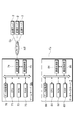
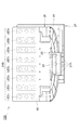
背面透過パネル90は、保持フレーム26の枠体26bにおける保持部材23の背面側部分に平板状で起立するように設置された透過性を有するパネルである。また、背面プレート91は、基台27の一部分であり、背面透過パネル90よりも奥側で起立している。さらに、LED支持板92には、上述したLED21に対応する高さ位置に横1列に並んだLED21からなる下方発光体21Aと、下方発光体21Aの上側に配置された横3列×縦8列の合計24個のLED21からなる側方発光体21Bとが取り付けられている。すなわち、図16に示すように、側方発光体21Bは、向かって左側から順にLED〜LEDのLED21群が縦3つに並んで配置されている。 The rear transmissive panel 90 is a transmissive panel installed so as to stand upright in a flat plate shape on the rear side portion of the holding member 23 in the frame body 26 b of the holding frame 26. Further, the back plate 91 is a part of the base 27, and stands up behind the back transmission panel 90. Further, the LED support plate 92 includes a lower light emitter 21A composed of LEDs 21 arranged in a horizontal row at a height corresponding to the LED 21 described above, and 3 horizontal rows × 8 vertical columns arranged above the lower light emitter 21A. A side light emitter 21B composed of a total of 24 LEDs 21 in a row is attached. That is, as shown in FIG. 16, the side light emitter 21 </ b> B is configured by arranging three LED 21 groups of LEDs 1 to 8 in order from the left side.

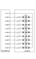
このようなフィギア設置ユニット15Aを備えるゲームマシンにおいては、下方発光体21A及び側方発光体21Bの各LED21が、本発明における発光体に相当し、各LED21は上述した発光制御回路50によって制御される。ここで、発光制御回路50と、側方発光体21Bを構成する各LED〜LEDが並列に接続されたLED回路93とを示す回路図を図17に示す。発光制御回路50は、図17に示すように、側方発光体21Bを構成する各LED〜LEDに共通する信号を出力するLEDコモンラインと、各LED〜LEDを独立して点灯させるための信号を出力するLED信号ライン〜LED信号ラインとを有している。LED回路93は、LEDコモンラインに接続されるコモンラインに各LED〜LEDが並列に接続され、各LED〜LEDは、LED信号ライン〜LED信号ラインに対して、抵抗体を介してLEDが3個ずつ直列に接続されている。さらに、下方発光体21Aを点灯させるための信号を出力するLED信号ラインも有している。 In a gaming machine equipped with such a figure installation unit 15A, each LED 21 of the lower light emitter 21A and the side light emitter 21B corresponds to the light emitter in the present invention, and each LED 21 is controlled by the light emission control circuit 50 described above. The Here, FIG. 17 shows a circuit diagram showing the light emission control circuit 50 and the LED circuit 93 in which the LEDs 1 to 8 constituting the side light emitter 21B are connected in parallel. As shown in FIG. 17, the light emission control circuit 50 independently turns on the LED common lines that output signals common to the LEDs 1 to 8 that constitute the side light emitter 21 </ b> B, and the LEDs 1 to 8. LED signal line 1 to LED signal line 8 for outputting a signal for generating the signal. LED circuit 93, the LED 1 ~LED 8 to a common line connected to the LED common line are connected in parallel, each LED 1 ~LED 8, to the LED signal line 1 ~LED signal line 8, the resistor Three LEDs are connected in series via each other. Furthermore, it also has an LED signal line L that outputs a signal for lighting the lower light emitter 21A.

また、メインCPU42は、発光態様決定手段として作動する際、図7に示す発光態様データベース44aと同等のデータベースを利用することが好適であるが、各遊技状態において、各LED〜LED毎に発光態様を規定したり、個々のLED21毎に発光態様を規定したりしてもよい。この場合には、一つの発光体を用いた場合に比べて、多様な発光態様を実現することができるため、遊技の興趣がさらに向上する。 Further, when operating as the light emission mode determination means, the main CPU 42 preferably uses a database equivalent to the light emission mode database 44a shown in FIG. 7, but for each LED 1 to LED 8 in each gaming state. The light emission mode may be defined, or the light emission mode may be defined for each individual LED 21. In this case, since various light emission modes can be realized as compared with the case where one light emitter is used, the interest of the game is further improved.

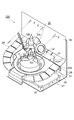
以上で説明したフィギア設置ユニット15AにおけるLED21の発光状態は、図18に示すように、フィギア30には下方からの照射光αと後方からの照射光βとが照射される。すなわち、下方発光体21Aから出射された光が保持部材23を透過して、保持部材23の周壁面23aから光αを放出し、フィギア30を下方から照らす。また、側方発光体21Bから出射された光βが背面透過パネル90を透過して、フィギア30を後方から照らす。そのため、照射光α及び照射光βの一部は、フィギア30のフィギア本体部32の入射部(例えば、フィギア本体部32の脚部分32a及び背面部32c)にあたり、上述した実施形態と同様にフィギア本体部32内を透過して、出射部(例えば、フィギア本体部32の胴部分32b)から出射される。   In the light emission state of the LED 21 in the figure installation unit 15A described above, as shown in FIG. 18, the figure 30 is irradiated with the irradiation light α from below and the irradiation light β from behind. That is, the light emitted from the lower light emitter 21A passes through the holding member 23, emits light α from the peripheral wall surface 23a of the holding member 23, and illuminates the figure 30 from below. Further, the light β emitted from the side light emitter 21B passes through the rear transmission panel 90 and illuminates the figure 30 from the rear. Therefore, a part of the irradiation light α and the irradiation light β hits the incident part of the figure main body part 32 of the figure 30 (for example, the leg part 32a and the back part 32c of the figure main body part 32), as in the above-described embodiment. The light passes through the main body 32 and is emitted from the emission portion (for example, the trunk portion 32b of the figure main body 32).

すなわち、このフィギア設置ユニット15Aが採用されたゲームマシンにおいても、上述したフィギア設置ユニット15が採用されたゲームマシン10同様、遊技者に対して視認可能に配置されたフィギア30自体の色があたかも変化したかのような視覚的効果を遊技者に与えることができる。特にこのようなフィギア設置ユニット15Aの場合、フィギア30に対して複数方向から照射光α,βが照射されるため、より複雑な視覚的効果を奏することができる。   That is, in the game machine using the figure installation unit 15A, the color of the figure 30 itself arranged so as to be visible to the player changes as in the game machine 10 using the figure installation unit 15 described above. It is possible to give the player a visual effect as if he did. Particularly, in the case of such a figure installation unit 15A, the irradiation light α and β is irradiated on the figure 30 from a plurality of directions, so that a more complicated visual effect can be achieved.

また、上述した効果と同等の視覚的効果を奏するために、図19に示すようなLED21が内蔵されたフィギア30Aを用いることも可能である。すなわち、このフィギア30Aは、台座部31の天頂部33aに6つのLED21が設けられている点、このLED21に対する電気信号が入力される端子94が台座部31に設けられている点、突起部33bが台座部31の天頂部33aの端部に設けられている点で異なる。このようなフィギア30Aを採用する場合には、ゲームマシン10のように遊技機自体がLED21を有する必要はなく、発光制御回路50からの電気信号が直接フィギア30Aに送られる。すなわち、このフィギア30Aが適用されるゲームマシンでは、メインCPU42が発光態様決定手段として決定した発光態様に従って、発光制御回路50からフィギア30AのLED21に対する電気信号が端子94を介してフィギア30Aに送られ、フィギア30AのLED21が発光する。つまり、フィギア30AのLED21は、発光制御回路50によって制御されている。   In order to achieve a visual effect equivalent to the above-described effect, it is possible to use a figure 30A in which an LED 21 as shown in FIG. 19 is incorporated. In other words, the figure 30A has a point that six LEDs 21 are provided at the zenith 33a of the pedestal 31, a terminal 94 to which an electric signal to the LEDs 21 is input is provided at the pedestal 31, and a protrusion 33b. Is different in that it is provided at the end of the zenith 33a of the pedestal 31. When such a figure 30A is employed, it is not necessary for the gaming machine itself to have the LED 21 as in the game machine 10, and an electric signal from the light emission control circuit 50 is directly sent to the figure 30A. That is, in a game machine to which the figure 30A is applied, an electrical signal for the LED 21 of the figure 30A is sent from the light emission control circuit 50 to the figure 30A via the terminal 94 in accordance with the light emission form determined by the main CPU 42 as the light emission form determining means. The LED 21 of the figure 30A emits light. That is, the LED 21 of the figure 30 </ b> A is controlled by the light emission control circuit 50.

そして、このフィギア30Aに内蔵されたLED21からの発光は、フィギア本体部32の脚座部(入射部)36からフィギア本体部32内に入射される。そして、フィギア本体部32内を透過して、出射部(例えば、フィギア本体部32の人形部37)から出射される。この出射部37からの出射光により、遊技者に対して視認可能に配置されたフィギア30A自体の色があたかも変化したかのような視覚的効果を遊技者に与えることができ、上述した実施形態と同様、遊技者の興趣が十分に保たれる。特にこのようなフィギア30Aの場合、フィギア30A毎に、LED21の数を変えたりLED21の内蔵発光素子の種類を変えたりすることができるため、発光制御回路50からの電気信号が画一的なものであっても、フィギア30A毎に様々な発光態様を実現することができる。また、LED21がゲームマシン10に設けられている場合に比べ、フィギア30Aの種別(グループ)や強さ等に応じた発光態様を容易に実現することができる。
第2実施形態
Light emitted from the LED 21 incorporated in the figure 30A enters the figure main body 32 from a leg seat (incident part) 36 of the figure main body 32. Then, the light passes through the figure main body portion 32 and is emitted from the emission portion (for example, the doll portion 37 of the figure main body portion 32). The emitted light from the emitting portion 37 can give the player a visual effect as if the color of the figure 30A itself arranged so as to be visible to the player has changed. As with, the player's interest is fully maintained. In particular, in the case of such a figure 30A, the number of LEDs 21 and the type of the light emitting element built in the LED 21 can be changed for each figure 30A, so that the electric signal from the light emission control circuit 50 is uniform. Even so, various light emission modes can be realized for each figure 30A. In addition, as compared with the case where the LED 21 is provided in the game machine 10, it is possible to easily realize the light emission mode according to the type (group) or strength of the figure 30 </ b> A.
Second embodiment

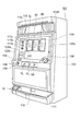
次に、本発明の第2実施形態に係る遊技機であるパチスロ機について説明する。図20は、第2実施形態に係るパチスロ機101の全体構成を示す斜視図である。パチスロ機101は、複数の図柄を複数列で可変表示する可変表示手段を有し、その可変表示手段により、複数のリールの可変表示を行い、遊技(以下「ゲーム」ともいう)を行えるように構成されている。
(パチスロ機の全体構成)
Next, a pachislot machine that is a gaming machine according to a second embodiment of the present invention will be described. FIG. 20 is a perspective view showing the overall configuration of the pachislot machine 101 according to the second embodiment. The pachislot machine 101 has variable display means for variably displaying a plurality of symbols in a plurality of columns, and the variable display means performs variable display of a plurality of reels so that a game (hereinafter also referred to as “game”) can be performed. It is configured.
(Pachislot machine overall configuration)

パチスロ機101は、筐体102の正面に画像表示部120を有し、筐体102の内部における画像表示部120の背面側に、機械式の3つのリール3L,3C,3Rが回転自在に横一列で配置されている。各リール3L,3C,3Rは外部から視認可能になっている。各リール3L,3C,3Rは、各々の外周面にそれぞれ21個ずつの複数種類の図柄を有する図柄列が描かれ、各図柄が可変表示される回転自在の可変表示手段を構成している。   The pachi-slot machine 101 has an image display unit 120 on the front surface of the housing 102, and three mechanical reels 3L, 3C, 3R are horizontally rotated on the back side of the image display unit 120 inside the housing 102. Arranged in a row. Each reel 3L, 3C, 3R is visible from the outside. Each reel 3L, 3C, 3R constitutes a rotatable variable display means in which a symbol row having 21 types of symbols is drawn on each outer peripheral surface, and each symbol is variably displayed.

また、パチスロ機101は、画像表示部120の下側にほぼ水平の台座部104を有し、その台座部104の左側に押しボタン操作でクレジットされているコインを賭ける設定を行うためのBETスイッチ105を有し、右側に遊技者がコインを投入するためのコイン投入口106を有している。なお、コイン投入口106は、コイン投入を示す信号を出力する投入コインセンサ106a(図21参照)を有している。   The pachi-slot machine 101 has a substantially horizontal pedestal 104 below the image display unit 120, and a BET switch for performing a setting for betting coins credited by a push button operation on the left side of the pedestal 104. 105 and a coin insertion slot 106 for a player to insert coins on the right side. The coin insertion slot 106 has an insertion coin sensor 106a (see FIG. 21) that outputs a signal indicating the insertion of coins.

さらに、パチスロ機101は、台座部104の前面に、左側から順に、遊技者がゲームで獲得したコインのクレジット/払出しを切替えるためのC/Pスイッチ108と、スタートスイッチ109とを有し、台座部104の前面中央に3個の停止ボタン7L,7C,7Rを有している。スタートスイッチ109は、各リール3L,3C,3Rの回転による図柄の可変表示の開始操作(ゲームの開始操作)を遊技者が行うためのスイッチである。停止ボタン7L,7C,7Rは遊技者が各リール3L,3C,3Rの回転(スクロール表示)をそれぞれ停止するための停止操作手段として設けられている。   Further, the pachislot machine 101 has a C / P switch 108 and a start switch 109 for switching the credit / payout of coins acquired by the player in the game in order from the left side on the front surface of the base portion 104. Three stop buttons 7L, 7C, and 7R are provided at the front center of the section 104. The start switch 109 is a switch for the player to perform a variable display start operation (game start operation) by rotating the reels 3L, 3C, and 3R. The stop buttons 7L, 7C, 7R are provided as stop operation means for the player to stop the rotation (scroll display) of the reels 3L, 3C, 3R.

そして、パチスロ機101は、筐体102の底部に、第1実施形態と同様のフィギア設置ユニット15と、コイン払出口110と、払い出されたコインを収めるコイン受け部111とを有し、筐体102の画像表示部120よりも上側の左側、右側にそれぞれスピーカ112L,112Rを有し、スピーカ112L,112Rの間に配当表示パネル113を有している。   The pachi-slot machine 101 has a figure installation unit 15 similar to that of the first embodiment, a coin payout opening 110, and a coin receiving portion 111 for storing paid out coins at the bottom of the housing 102. Speakers 112L and 112R are respectively provided on the left and right sides above the image display unit 120 of the body 102, and a payout display panel 113 is provided between the speakers 112L and 112R.

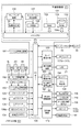
図21は、内部の構成を中心に示すパチスロ機101のブロック図である。パチスロ機101は、マイクロコンピュータ131を含む主制御基板171を中心に複数の構成要素を有している。その主制御基板171は、マイクロコンピュータ131と、乱数発生器135、サンプリング回路136、クロックパルス発生回路137および分周器138を有し、ランプ駆動回路159、ホッパー駆動回路163、払出完了信号回路165、表示部駆動回路167および発光制御回路50を有している。   FIG. 21 is a block diagram of the pachi-slot machine 101 centering on the internal configuration. The pachi-slot machine 101 has a plurality of components around a main control board 171 including a microcomputer 131. The main control board 171 includes a microcomputer 131, a random number generator 135, a sampling circuit 136, a clock pulse generation circuit 137, and a frequency divider 138, and includes a lamp driving circuit 159, a hopper driving circuit 163, and a payout completion signal circuit 165. The display unit driving circuit 167 and the light emission control circuit 50 are provided.

マイクロコンピュータ131は、メインCPU(Central Processing Unit)132と、RAM(Random Access Memory)133と、ROM(Read Only Memory)134とを有している。メインCPU132は、ROM134に記憶されているプログラムにしたがい作動して、I/Oポート39を介して他の構成要素との信号の入出力を行い、パチスロ機101全体の動作制御を行う。このメインCPU132は本発明における遊技態様制御手段を構成している。すなわち、メインCPU132は停止図柄の配列結果などの所定条件の成立により、遊技態様を通常ゲーム(通常遊技態様)から遊技者にとって多くの払出しメダルが期待できるボーナスゲーム(特別遊技態様)へ遊技態様を移行させる。   The microcomputer 131 includes a main CPU (Central Processing Unit) 132, a RAM (Random Access Memory) 133, and a ROM (Read Only Memory) 134. The main CPU 132 operates according to a program stored in the ROM 134, inputs / outputs signals to / from other components via the I / O port 39, and controls the operation of the entire pachislot machine 101. The main CPU 132 constitutes game mode control means in the present invention. That is, the main CPU 132 shifts the game mode from a normal game (normal game mode) to a bonus game (special game mode) where a player can expect a lot of payout medals when a predetermined condition such as a stop symbol arrangement result is established. Transition.

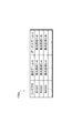
RAM133はメインCPU132が作動する際に用いるデータやプログラムが記憶され、例えば、後述するサンプリング回路136によりサンプリングされる乱数値がゲーム開始後、一時的に保持されるとともに、リール3L、3C、3Rのコードナンバ、図柄ナンバが記憶されている。ROM134にはメインCPU132が実行するプログラムと、恒久的なデータが記憶されている。パチスロ機101の場合、ROM134には図22に示す発光態様データベース134aが記憶されている。すなわち、発光態様データベース134aは、フィギアID毎に、通常ゲーム中における発光態様とボーナスゲーム中における発光態様とが格納されている。   The RAM 133 stores data and programs used when the main CPU 132 operates. For example, random numbers sampled by a sampling circuit 136 described later are temporarily held after the game starts, and the reels 3L, 3C, and 3R are also stored. Code number and design number are stored. The ROM 134 stores a program executed by the main CPU 132 and permanent data. In the case of the pachislot machine 101, the ROM 134 stores a light emission mode database 134a shown in FIG. That is, the light emission mode database 134a stores, for each figure ID, a light emission mode during the normal game and a light emission mode during the bonus game.

乱数発生器135は、メインCPU132の指示にしたがい作動して、一定範囲の乱数を発生させる。サンプリング回路136は、メインCPU132の指示にしたがい、乱数発生器135が発生させた乱数の中から任意の乱数を抽出し、その抽出した乱数をメインCPU132に入力する。クロックパルス発生回路137は、メインCPU132を作動させるための基準クロックを発生させ、分周器138はその基準クロックを一定周期で分周した信号をメインCPU132に入力する。   The random number generator 135 operates according to an instruction from the main CPU 132 to generate a certain range of random numbers. The sampling circuit 136 extracts an arbitrary random number from the random numbers generated by the random number generator 135 in accordance with an instruction from the main CPU 132, and inputs the extracted random number to the main CPU 132. The clock pulse generation circuit 137 generates a reference clock for operating the main CPU 132, and the frequency divider 138 inputs a signal obtained by dividing the reference clock at a constant period to the main CPU 132.

さらに、主制御基板171には、リール駆動ユニット150と、リール停止信号回路153とが接続されている。リール駆動ユニット150は、リール3L,3C,3Rのそれぞれの位置を検出するリール位置検出回路151と、各リール3L,3C,3Rを回転させるためのモータM1,M2,M3に駆動信号を入力するモータ駆動回路152を有している。このモータ駆動回路152から駆動信号が入力されることによって、モータM1,M2,M3が作動し、そのそれぞれがリール3L,3C,3Rを回転させる。リール停止信号回路153は、各停止ボタン7L,7C,7Rの停止操作に応じた停止信号を出力し、I/Oポート139を介してマイクロコンピュータ131に入力する。その他、主制御基板171は、スタートスイッチ109、BETスイッチ105、C/Pスイッチ108および投入コインセンサ106aが接続され、それぞれから信号が入力されるようになっている。   Further, a reel drive unit 150 and a reel stop signal circuit 153 are connected to the main control board 171. The reel drive unit 150 inputs drive signals to a reel position detection circuit 151 that detects the positions of the reels 3L, 3C, and 3R, and motors M1, M2, and M3 for rotating the reels 3L, 3C, and 3R. A motor drive circuit 152 is provided. When a drive signal is input from the motor drive circuit 152, the motors M1, M2, and M3 are operated, and each of them rotates the reels 3L, 3C, and 3R. The reel stop signal circuit 153 outputs a stop signal corresponding to the stop operation of each stop button 7L, 7C, 7R, and inputs it to the microcomputer 131 via the I / O port 139. In addition, the main control board 171 is connected to the start switch 109, the BET switch 105, the C / P switch 108, and the inserted coin sensor 106a, and a signal is input from each of them.

ランプ駆動回路159は各種ランプ(BETランプ117a,117b,117c)を点灯させるための信号を出力する。ホッパー駆動回路163はメインCPU132の制御にしたがいホッパー164を駆動させ、ホッパー164はコインの払出を行うための動作を行い、コイン払出口110からコインを払出させる。払出完了信号回路165は、接続されているコイン検出部166からコインの枚数値データを入力し、その枚数値が設定された枚数の値に達したときにコインの払出完了を通知する信号をメインCPU132に入力する。コイン検出部166は、ホッパー164により払出されたコインの枚数を計測し、その計測した枚数値のデータを払出完了信号回路165に入力する。表示部駆動回路167は、各表示部(払出表示部118、クレジット表示部119およびボーナス遊技情報表示部116)の表示動作を制御する。   The lamp driving circuit 159 outputs signals for lighting various lamps (BET lamps 117a, 117b, and 117c). The hopper drive circuit 163 drives the hopper 164 under the control of the main CPU 132, and the hopper 164 performs an operation for paying out coins, and pays out coins from the coin payout exit 110. The payout completion signal circuit 165 inputs coin number value data from the connected coin detection unit 166, and outputs a signal for notifying completion of coin payout when the number value reaches a set number value. Input to the CPU 132. The coin detection unit 166 measures the number of coins paid out by the hopper 164 and inputs data of the measured number value to the payout completion signal circuit 165. The display unit drive circuit 167 controls the display operation of each display unit (the payout display unit 118, the credit display unit 119, and the bonus game information display unit 116).

発光制御回路50は、メインCPU132からの指示に従い、フィギア設置ユニット15のLED21の各発光素子(赤色発光素子、青色発光素子、緑色発光素子)に対して発光信号を出力する。また、I/Oポート139に接続されたICチップリーダライタ20は、必要に応じて、フィギア30のICチップ34からフィギア記憶情報を読み取ってメインCPU132に入力し、メインCPU132からの情報をICチップ34に書き込んでフィギア記憶情報を更新する。   The light emission control circuit 50 outputs a light emission signal to each light emitting element (red light emitting element, blue light emitting element, green light emitting element) of the LED 21 of the figure installation unit 15 in accordance with an instruction from the main CPU 132. Further, the IC chip reader / writer 20 connected to the I / O port 139 reads the figure storage information from the IC chip 34 of the figure 30 and inputs it to the main CPU 132 as necessary, and the information from the main CPU 132 is inputted to the IC chip. The information stored in FIG. 34 is updated.

さらに、主制御基板171には副制御基板172が接続されている。副制御基板172は、主制御基板171から制御命令(コマンド)を入力して、液晶表示装置141(液晶表示装置141は画像表示部120を構成し、リール3L,3C,3Rの前面に配置され、その一部において透過表示が行われる)の表示制御及びスピーカ112L,112Rによる音声の出力制御を行う。この副制御基板172は主制御基板171を構成する回路基板とは別の回路基板上に構成され、図示しないマイクロコンピュータ(以下「サブマイクロコンピュータ」という)を主たる構成要素とし、スピーカ112L,112Rから出力される音声を制御する音源IC、増幅器としてのパワーアンプ、液晶表示装置141の表示制御手段として作動する画像制御回路を有している。   Further, a sub control board 172 is connected to the main control board 171. The sub-control board 172 inputs a control command (command) from the main control board 171, and the liquid crystal display device 141 (the liquid crystal display device 141 constitutes the image display unit 120 and is arranged on the front surface of the reels 3L, 3C, 3R. , Part of which is transparently displayed) and sound output control by the speakers 112L and 112R. The sub-control board 172 is formed on a circuit board different from the circuit board constituting the main control board 171, and includes a microcomputer (not shown) (hereinafter referred to as “sub-microcomputer”) as a main component, and the speakers 112L and 112R. A sound source IC that controls output sound, a power amplifier as an amplifier, and an image control circuit that operates as display control means of the liquid crystal display device 141 are provided.

以上の構成を有するパチスロ機101では、遊技者のスタートレバー109の操作に応じて、各リール3L,3C,3Rが回転して図柄の可変表示が行われ、遊技者による停止ボタン7L,7C,7Rの操作に応じて各リール3L,3C,3Rが停止する。このとき、画像表示部120における図柄表示領域121L,121C,121R内において、所定の有効ライン上に停止表示される図柄が特定の図柄になるときに、メダルや硬貨等のゲームで使用する媒体(以下「コイン」という)の払出を行い、さらにメインCPU132が遊技態様制御手段として作動して、通常遊技状態から通常遊技状態よりも遊技者にとって有利なBB(ビッグボーナス)やRB(レギュラーボーナス)といった特定遊技状態に遊技状態を移行させるようになっている。
(パチスロ機の動作内容)
In the pachislot machine 101 having the above-described configuration, the reels 3L, 3C, 3R are rotated according to the operation of the start lever 109 by the player, and the symbols are variably displayed, and the stop button 7L, 7C, Each reel 3L, 3C, 3R stops according to the operation of 7R. At this time, in the symbol display areas 121L, 121C, 121R in the image display unit 120, when a symbol stopped and displayed on a predetermined active line becomes a specific symbol, a medium (such as a medal or a coin) used in a game ( The main CPU 132 operates as a game mode control means, and BB (Big Bonus) or RB (Regular Bonus) that is more advantageous to the player than the normal game state is performed. The game state is shifted to the specific game state.
(Operation contents of pachislot machine)

次に、パチスロ機101の動作内容のうち、主制御基板171による制御処理の手順について、図23及び図24のフローチャートを参照して説明する。図23はパチスロ機101において、主制御基板171より実行される演出制御処理の動作手順を示すフローチャートである。なお、図23及び図24では、ステップをSと略記している。
(演出制御処理の動作手順)
Next, among the operation contents of the pachi-slot machine 101, the procedure of the control processing by the main control board 171 will be described with reference to the flowcharts of FIGS. FIG. 23 is a flowchart showing an operation procedure of effect control processing executed by the main control board 171 in the pachi-slot machine 101. 23 and 24, step is abbreviated as S.
(Operation procedure of production control process)

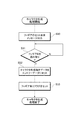
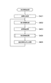
メインCPU132が演出制御処理を開始すると、ステップ401〜405までの各ステップを順次実行して、初期化処理、表示制御処理、音制御処理、発光制御処理および遊技媒体払出し処理を順次実行する。以後、このステップ402〜405を順次実行する繰返ルーチンに進む。   When the main CPU 132 starts the effect control process, steps 401 to 405 are sequentially executed, and an initialization process, a display control process, a sound control process, a light emission control process, and a game medium payout process are sequentially executed. Thereafter, the process proceeds to a repeating routine for sequentially executing Steps 402 to 405.

ステップ402の表示制御処理では、メインCPU132が副制御基板172に指示して、液晶表示装置141に画像を表示させる。続くステップ403の音声制御処理では、メインCPU132が副制御基板172に指示して、スピーカ112L,112Rから音声を出力させる。   In the display control process of step 402, the main CPU 132 instructs the sub control board 172 to display an image on the liquid crystal display device 141. In the subsequent audio control process in step 403, the main CPU 132 instructs the sub control board 172 to output audio from the speakers 112L and 112R.

さらに、ステップ404に進むと発光制御処理が行われる。この発光制御処理は、図24に示すフローチャートに沿って行われる。すなわち、発光制御処理を開始すると、ステップ411に進み、ICチップリーダライタ20からのフィギアIDの読み取り処理を行う。続いてステップ412に進み、メインCPU132が発光態様決定手段として作動し、現在のゲーム状態が通常ゲーム状態かボーナスゲーム状態かを判断し、ICチップリーダライタ20によって読み取ったフィギアIDに基づいて、発光態様データベース134aからLED21の発光態様を決定する。そして、メインCPU132によって発光態様が決定されると、ステップ413において、発光制御回路50が決定された発光態様に従ったLED21の発光制御をおこなう。   Further, in step 404, a light emission control process is performed. This light emission control process is performed according to the flowchart shown in FIG. That is, when the light emission control process is started, the process proceeds to step 411, where the figure ID reading process from the IC chip reader / writer 20 is performed. Subsequently, the process proceeds to step 412, where the main CPU 132 operates as a light emission mode determination means, determines whether the current game state is a normal game state or a bonus game state, and emits light based on the figure ID read by the IC chip reader / writer 20. The light emission mode of the LED 21 is determined from the mode database 134a. When the main CPU 132 determines the light emission mode, in step 413, the light emission control circuit 50 controls the light emission of the LED 21 according to the determined light emission mode.

従って、このパチスロ機101においても、フィギア設置ユニット15に図5に示したフィギア30がセットされると、LED21からフィギア30のフィギア本体部32の入射部32aに対して照射された光が、フィギア30のフィギア本体部32内を透過して出射部32bから外部に出射される。従って、このパチスロ機101においても、フィギア30のICチップ34に記憶されたフィギアIDに基づきLED21の発光態様を変化させることで、フィギア30の外観を変えることが可能である。従って、第1実施形態に示したゲームマシン10同様、このパチスロ機101においても遊技者の興趣が十分に保たれる。また、遊技者はボーナスゲームへの移行を期待しつつ遊技を繰り返すが、随時、発光態様を変化させることで遊技者の期待感が膨らむため、遊技者の興趣の維持及びさらなる向上を図ることもできる。
第3実施形態
Therefore, also in this pachislot machine 101, when the figure 30 shown in FIG. 5 is set in the figure installation unit 15, the light emitted from the LED 21 to the incident part 32 a of the figure main body 32 of the figure 30 is changed. 30 is transmitted through the figure main body 32 and emitted from the emitting part 32b to the outside. Therefore, also in this pachislot machine 101, the appearance of the figure 30 can be changed by changing the light emission mode of the LED 21 based on the figure ID stored in the IC chip 34 of the figure 30. Therefore, like the game machine 10 shown in the first embodiment, the player's interest is sufficiently maintained in the pachislot machine 101. In addition, the player repeats the game while expecting a transition to the bonus game, but the player's expectation increases by changing the light emission mode from time to time, so the player's interest can be maintained and further improved. it can.
Third embodiment

次に、本発明の第3実施形態に係る遊技機であるパチンコ遊技機について説明する。図25は、第3実施形態に係るパチンコ遊技機201の全体構成を示す斜視図である。本実施形態では、パチンコ遊技機201がデジタルパチンコ遊技機(デジパチ、第1種パチンコ遊技機と称される)となっている。
(パチンコ遊技機の全体構成)
Next, a pachinko gaming machine that is a gaming machine according to a third embodiment of the present invention will be described. FIG. 25 is a perspective view showing an overall configuration of a pachinko gaming machine 201 according to the third embodiment. In this embodiment, the pachinko gaming machine 201 is a digital pachinko gaming machine (referred to as a digital pachinko or first type pachinko gaming machine).
(Overall configuration of pachinko machines)

図25に示すパチンコ遊技機201は、遊技場(ホール)の所定の設置枠に収容されて設置される外枠202を備えている。外枠202の正面側には、外枠202に対して回動可能に設けられたベースドア(内枠)203が配設され、ベースドア203内には、図示しない遊技盤が組み込まれている。また、外枠202の正面には、フロント扉205が設けられている。フロント扉205は、遊技盤の正面を覆うとともに、ベースドア203の正面側に回動可能に設置されている。   A pachinko gaming machine 201 shown in FIG. 25 includes an outer frame 202 that is housed and installed in a predetermined installation frame of a game hall (hall). A base door (inner frame) 203 is provided on the front side of the outer frame 202 so as to be rotatable with respect to the outer frame 202, and a game board (not shown) is incorporated in the base door 203. . A front door 205 is provided in front of the outer frame 202. The front door 205 covers the front of the game board and is rotatably installed on the front side of the base door 203.

また、パチンコ遊技機201には、プリペイドカードなどが挿入されると、当該プリペイドカードの残高に応じて、遊技球が貸し出されるように構成されたカードユニットが隣接して併設されている。   In addition, the pachinko gaming machine 201 is adjacently provided with a card unit configured such that when a prepaid card or the like is inserted, game balls are lent out according to the balance of the prepaid card.

フロント扉205は、その中央の略全域にガラス板205aを備え、その内側の遊技盤が視認可能な構成とされている。フロント扉205の下部には、カードユニットのカード返却操作や遊技球の貸し出し(玉貸し)操作等を行う玉貸し操作関連ボタンを有する玉貸し操作パネル228が設けられている。また、この玉貸し操作パネル228には、所定の操作を行う決定ボタン220aおよび選択ボタン220b,220cが設けられている。   The front door 205 is provided with a glass plate 205a in an almost entire area of the center thereof so that a game board inside thereof can be visually recognized. Below the front door 205, a ball lending operation panel 228 having a ball lending operation related button for performing a card return operation of the card unit, a lending (ball lending) operation of a game ball, and the like is provided. Further, the ball lending operation panel 228 is provided with a determination button 220a and selection buttons 220b and 220c for performing a predetermined operation.

また、フロント扉205の下側には、外枠202に対して開閉可能な皿パネル206が設置されている。この皿パネル206の正面側には、カードユニットにより貸し出された遊技球および後述する入賞口に入球した場合に払い出される遊技球を受け止める上皿206aと、この上皿206aの満杯時に球出口206dの内方で溢れた遊技球を受け止める下皿206bと、この下皿206bの右側に設けられた発射ハンドル206cとが配置されている。   A dish panel 206 that can be opened and closed with respect to the outer frame 202 is installed below the front door 205. On the front side of the plate panel 206, there are an upper plate 206a for receiving a game ball lent out by the card unit and a game ball to be paid out when entering a winning port described later, and a ball outlet 206d when the upper plate 206a is full. A lower plate 206b that catches the game ball overflowing inward of the ball and a firing handle 206c provided on the right side of the lower plate 206b are arranged.

発射ハンドル206cは、上皿206aに受け止められている遊技球を発射するためのもので、皿パネル206に対して回動自在に設けられ、遊技者は発射ハンドル206cを操作することによりパチンコ遊技を進めることができる。この発射ハンドル206cが遊技者によって握持され、かつ、時計回り方向へ回動操作されたときに、その回動角度に応じて、発射ハンドル206cの背面側に設けられた発射モータに電力が供給され、遊技球が遊技盤に順次発射される。   The launch handle 206c is for launching a game ball received by the upper plate 206a, and is provided so as to be rotatable with respect to the plate panel 206. The player operates the launch handle 206c to play a pachinko game. You can proceed. When the firing handle 206c is gripped by the player and is turned clockwise, power is supplied to the firing motor provided on the back side of the firing handle 206c according to the turning angle. Then, game balls are sequentially fired onto the game board.

また、下皿206bの左側の設置部206eには、上述したフィギア設置ユニット15が設けられている。   Further, the above-described figure installation unit 15 is provided in the installation part 206e on the left side of the lower plate 206b.

図26は、パチンコ遊技機201の内部の構成を中心に示すブロック構成図である。パチンコ遊技機201は、主制御回路230、払出・発射制御回路280、電源供給ユニット224を中心に複数の構成要素を有し、この電源供給ユニット224は、主制御回路230および払出・発射制御回路280にそれぞれ接続され各々への電力供給が可能とされている。主制御回路230は、1チップマイコンより構成されているメインCPU(Central Processing Unit)231、メインROM(Read Only Memory)232およびメインRAM(Random Access Memory)233を有し、他に初期リセット回路234と、画像制御回路250と、音声制御回路260、ランプ制御回路270および発光制御回路50を有している。   FIG. 26 is a block configuration diagram mainly showing the internal configuration of the pachinko gaming machine 201. The pachinko gaming machine 201 has a plurality of components, mainly a main control circuit 230, a payout / launch control circuit 280, and a power supply unit 224. The power supply unit 224 includes the main control circuit 230 and a payout / launch control circuit. 280 is connected to each 280 and can supply power to each. The main control circuit 230 has a main CPU (Central Processing Unit) 231, a main ROM (Read Only Memory) 232, and a main RAM (Random Access Memory) 233 which are constituted by a one-chip microcomputer, and an initial reset circuit 234. An image control circuit 250, an audio control circuit 260, a lamp control circuit 270, and a light emission control circuit 50.

メインCPU231は、後述するVカウントスイッチ211Sなどから遊技球の検出信号を入力する一方、メインROM232に記憶されている制御プログラムにしたがい作動して、パチンコ遊技機201における大当り抽選や、賞球排出といったパチンコ遊技機201全体の動作制御を司る。メインCPU231は本発明における遊技態様制御手段を構成している。すなわち、メインCPU231は大当り抽選の結果や遊技状態の消化などの所定条件の成立により、遊技態様を通常遊技態様から遊技者にとって多くの出玉が期待できる特別遊技態様(大当り)へ遊技態様を移行させる。なお、パチンコ遊技機201では、遊技態様(遊技状態)として、通常遊技状態、確変遊技状態および大当り(大当り遊技状態)がある。   The main CPU 231 inputs a detection signal of a game ball from a V count switch 211S or the like which will be described later, and operates according to a control program stored in the main ROM 232 to perform a big hit lottery or a prize ball discharge in the pachinko gaming machine 201. It controls the operation of the entire pachinko gaming machine 201. The main CPU 231 constitutes game mode control means in the present invention. That is, the main CPU 231 shifts the game mode from the normal game mode to the special game mode (big hit) where a lot of balls can be expected for the player by the establishment of predetermined conditions such as the result of the big win lottery and the digestion of the game state. Let me. In the pachinko gaming machine 201, there are a normal gaming state, a probability variation gaming state, and a big hit (big hit gaming state) as gaming modes (gaming states).

メインROM232には、メインCPU231が実行する制御プログラムと、恒久的なデータが記憶されている。パチンコ遊技機201の場合、メインROM232には図27に示す発光態様データベース232aが記憶されている。すなわち、発光態様データベース232aは、フィギアID毎に、通常遊技状態における発光態様、確変遊技状態における発光態様、大当り遊技状態における発光態様とが格納されている。   The main ROM 232 stores a control program executed by the main CPU 231 and permanent data. In the case of the pachinko gaming machine 201, the main ROM 232 stores a light emission mode database 232a shown in FIG. That is, the light emission mode database 232a stores, for each figure ID, a light emission mode in the normal gaming state, a light emission mode in the probability variation gaming state, and a light emission mode in the big hit gaming state.

メインRAM33はメインCPU231が作動する際に用いるデータやプログラムが一時的に記憶されるようになっている。初期リセット回路234は、リセット信号をメインCPU231に定期的に出力する。このリセット信号により、メインCPU231は制御プログラムの先頭から処理を実行する。   The main RAM 33 temporarily stores data and programs used when the main CPU 231 operates. The initial reset circuit 234 periodically outputs a reset signal to the main CPU 231. With this reset signal, the main CPU 231 executes processing from the beginning of the control program.

また、主制御回路230には、Vカウントスイッチ211Sをはじめとする各スイッチ等が接続されている。Vカウントスイッチ211Sは大入賞口211内に設けられたVゾーンを通過した遊技球の個数を計測し、計測結果を示す検出信号を主制御回路230に出力する。カウントスイッチ211CSは大入賞口211に入賞した遊技球の個数を計測し、計測結果を示す検出信号を主制御回路230に出力する。   Further, the main control circuit 230 is connected to each switch including the V count switch 211S. The V count switch 211S measures the number of game balls that have passed through the V zone provided in the special winning opening 211, and outputs a detection signal indicating the measurement result to the main control circuit 230. The count switch 211CS measures the number of game balls won in the big winning opening 211 and outputs a detection signal indicating the measurement result to the main control circuit 230.

一般入賞口スイッチ212Sは各一般入賞口212a〜212dに入賞した遊技球の検出信号を主制御回路230に出力する。作動ゲートスイッチ210Sは普通図柄作動ゲート210を通過する遊技球の検出信号を主制御回路230に出力する。始動入賞口スイッチ209Sは始動入賞口209に入賞した遊技球の検出信号を主制御回路230に出力する。   The general winning opening switch 212 </ b> S outputs a detection signal of a game ball won to each of the general winning openings 212 a to 212 d to the main control circuit 230. The operation gate switch 210 </ b> S outputs a detection signal of the game ball passing through the normal symbol operation gate 210 to the main control circuit 230. The start winning port switch 209 </ b> S outputs a detection signal of a game ball won in the start winning port 209 to the main control circuit 230.

始動口ソレノイド209Lは始動入賞口209に設けられた一対の羽根209a,209aを開閉させ、大入賞口ソレノイド211Lは大入賞口211のシャッタを開閉させる。シーソーソレノイド211Mは大入賞口211の図示しないシーソーを駆動する。バックアップクリアスイッチ226は、電断時等におけるバックアップデータを操作者の操作に応じてクリアする。   The start opening solenoid 209L opens and closes a pair of blades 209a and 209a provided in the start winning opening 209, and the large winning opening solenoid 211L opens and closes the shutter of the large winning opening 211. The seesaw solenoid 211M drives a seesaw (not shown) of the special winning opening 211. The backup clear switch 226 clears backup data in the event of a power interruption or the like according to the operation of the operator.

パチンコ遊技機201では、始動入賞口スイッチ209Sが遊技球の入賞を検出して検出信号を出力したときに乱数抽出および抽出した乱数を用いた抽選処理を行わせ、その抽選結果に基づき、液晶表示装置215における装飾図柄を決定している。   In the pachinko gaming machine 201, when the start winning port switch 209S detects winning of a game ball and outputs a detection signal, random number extraction is performed, and a lottery process using the extracted random number is performed. Based on the lottery result, a liquid crystal display The decorative design in the device 215 is determined.

メインCPU231は、大当りとなったときに大入賞口ソレノイド211Lに駆動信号を出力することによって、大入賞口211を開放させる。また、大入賞口211を開放させると、所定数(例えば10個)の遊技球の入賞または所定時間(例えば30秒)の経過を条件として閉鎖させる。また、メインCPU231は、選択ボタン220b,220c、決定ボタン220aからの信号にしたがい電源供給ユニット224を制御する。   The main CPU 231 opens the big prize opening 211 by outputting a drive signal to the big prize opening solenoid 211L when the big hit is made. Also, when the special winning opening 211 is opened, the game is closed on the condition that a predetermined number (for example, 10) of game balls have been won or a predetermined time (for example, 30 seconds) has passed. The main CPU 231 controls the power supply unit 224 in accordance with signals from the selection buttons 220b and 220c and the determination button 220a.

そして、メインCPU231は、液晶表示装置215を用いた装飾図柄の可変表示、リーチ演出、予告演出といった演出に必要な制御を行う一方、画像制御回路250を作動させて所定の画像を液晶表示装置215に表示させる。また、メインCPU231は、音声制御回路260およびランプ制御回路270を作動させて、スピーカ217L、217Rを用いた音声出力による演出や装飾ランプ218L、218Rの点滅表示による演出に必要な制御も行う。   The main CPU 231 performs control necessary for effects such as variable display of decorative symbols, reach effects, and notice effects using the liquid crystal display device 215, while operating the image control circuit 250 to display a predetermined image on the liquid crystal display device 215. To display. Further, the main CPU 231 operates the audio control circuit 260 and the lamp control circuit 270 to perform control necessary for the effect by the sound output using the speakers 217L and 217R and the effect by the blinking display of the decoration lamps 218L and 218R.

画像制御回路250は、VDP(Video Display Processor)251と、D/Aコンバータ252と、初期リセット回路253と、画像データROM(画像記憶手段)254a,254bとを有している。VDP251は、メインCPU231で決定された液晶表示装置215に表示させる内容に応じた画像を形成し、その形成された画像をD/Aコンバータ252に出力する。D/Aコンバータ252はVDP251から出力される画像データをD/A変換して、変換により得られたアナログ信号を液晶表示装置215に出力し、画像を表示させる。初期リセット回路253はメインCPU231からのリセット命令を受けて、VDP251を初期状態に戻す処理を実行する。画像データROM254aには装飾図柄、特別図柄、キャラクタ、背景などを示す画像のデータ(画像データ)が記憶され、画像データROM254bには、各種画像データを液晶表示装置215に表示させるための画像データが記憶されている。   The image control circuit 250 includes a VDP (Video Display Processor) 251, a D / A converter 252, an initial reset circuit 253, and image data ROMs (image storage means) 254a and 254b. The VDP 251 forms an image according to the content to be displayed on the liquid crystal display device 215 determined by the main CPU 231, and outputs the formed image to the D / A converter 252. The D / A converter 252 D / A converts the image data output from the VDP 251 and outputs an analog signal obtained by the conversion to the liquid crystal display device 215 to display an image. The initial reset circuit 253 receives the reset command from the main CPU 231 and executes processing for returning the VDP 251 to the initial state. Image data ROM 254a stores image data (image data) indicating decorative symbols, special symbols, characters, backgrounds, and the like, and image data ROM 254b stores image data for displaying various image data on the liquid crystal display device 215. It is remembered.

音声制御回路260は、音声信号を生成する音源IC261と、生成された音声信号を増幅するAMP262と、各種の演出に用いられる音声データを記憶している音声データROM263とを有している。   The audio control circuit 260 includes a sound source IC 261 that generates an audio signal, an AMP 262 that amplifies the generated audio signal, and an audio data ROM 263 that stores audio data used for various effects.

ランプ制御回路270は、装飾ランプ218L、218Rの点滅パターンを示す装飾データを記憶した装飾データROM271と、メインCPU231からの指示にしたがい、装飾データROM271に記憶されている装飾データを用いて装飾ランプ218L、218Rを点滅させるドライブ回路272とを有している。   The lamp control circuit 270 uses the decoration data ROM 271 that stores decoration data indicating the blinking pattern of the decoration lamps 218L and 218R, and the decoration lamp 218L using the decoration data stored in the decoration data ROM 271 in accordance with an instruction from the main CPU 231. And a drive circuit 272 for blinking 218R.

払出・発射制御回路280は、主制御回路230の制御にしたがい払出装置281を作動させて所定数の遊技球を賞球として払出させて、大入賞口211に遊技球が入賞した際に賞球を払い出す。また、払出・発射制御回路280は、発射ハンドル206cと、発射モータを有する発射装置282とを作動させ、発射装置282によって遊技球を遊技盤上の遊技領域に向けて発射させる。   The payout / launch control circuit 280 operates the payout device 281 according to the control of the main control circuit 230 to pay out a predetermined number of game balls as prize balls, and when the game balls win the big prize opening 211, the prize balls Pay out. The payout / firing control circuit 280 operates the firing handle 206c and the launching device 282 having a launching motor, and causes the launching device 282 to launch a game ball toward a game area on the game board.

電源供給ユニット224は、主制御回路230の制御にしたがい、主制御回路230および払出・発射制御回路280への電力供給を行うとともに、払出・発射制御回路280、主制御回路230への電力供給を制限する。
(パチンコ遊技機の動作内容)
The power supply unit 224 supplies power to the main control circuit 230 and the payout / launch control circuit 280 according to the control of the main control circuit 230, and supplies power to the payout / launch control circuit 280 and the main control circuit 230. Restrict.
(Operation details of pachinko machines)

パチンコ遊技機201の動作内容のうち、主制御回路230による制御処理の手順については、上述したパチスロ機101の主制御基板171による制御処理(図23及び図24参照)と同様にして行われる。すなわち、メインCPU231が演出制御処理を開始すると、パチスロ機101同様、初期化処理、表示制御処理、音制御処理、発光制御処理および遊技媒体払出し処理が順次実行され、表示制御処理から遊技媒体払出し処理が順次実行される繰返ルーチンとなる。   Among the operation contents of the pachinko gaming machine 201, the procedure of the control processing by the main control circuit 230 is performed in the same manner as the control processing (see FIGS. 23 and 24) by the main control board 171 of the pachislot machine 101 described above. That is, when the main CPU 231 starts the effect control process, the initialization process, the display control process, the sound control process, the light emission control process, and the game medium payout process are sequentially executed as in the pachislot machine 101, and the display control process to the game medium payout process. Are repeated routines executed sequentially.

そして、表示制御処理では、メインCPU231が画像制御回路250に指示して、液晶表示装置215に画像を表示させる。続く音声制御処理では、メインCPU231が音声制御回路260に指示して、スピーカ217L,217Rから音声を出力させる。   In the display control process, the main CPU 231 instructs the image control circuit 250 to display an image on the liquid crystal display device 215. In the subsequent audio control process, the main CPU 231 instructs the audio control circuit 260 to output audio from the speakers 217L and 217R.

さらに、発光制御処理が図24に示したフローチャートと同様にして行われる。すなわち、発光制御処理を開始すると、ICチップリーダライタ20からのフィギアIDの読み取り処理を行う。続いて、メインCPU231が発光態様決定手段として作動し、現在の遊技態様を判断し、ICチップリーダライタ20によって読み取ったフィギアIDに基づいて、発光態様データベース232aからLED21の発光態様を決定する。そして、メインCPU231によって発光態様が決定されると、発光制御回路50が決定された発光態様に従ったLED21の発光制御をおこなう。   Further, the light emission control processing is performed in the same manner as the flowchart shown in FIG. That is, when the light emission control process is started, the figure ID reading process from the IC chip reader / writer 20 is performed. Subsequently, the main CPU 231 operates as the light emission mode determination means, determines the current game mode, and determines the light emission mode of the LED 21 from the light emission mode database 232a based on the figure ID read by the IC chip reader / writer 20. When the main CPU 231 determines the light emission mode, the light emission control circuit 50 controls the light emission of the LED 21 according to the determined light emission mode.

従って、このパチンコ遊技機201においても、フィギア設置ユニット15に図5に示したフィギア30がセットされると、LED21からフィギア30のフィギア本体部32の入射部32aに対して照射された光が、フィギア30のフィギア本体部32内を透過して出射部32bから外部に出射される。従って、このパチンコ遊技機201においても、フィギア30のICチップ34に記憶されたフィギアIDに基づきLED21の発光態様を変化させることで、フィギア30の外観を変えることが可能である。従って、第1実施形態に示したゲームマシン10や第2実施形態に示したパチスロ機101同様、このパチンコ遊技機201においても遊技者の興趣が十分に保たれる。   Therefore, also in this pachinko gaming machine 201, when the figure 30 shown in FIG. 5 is set in the figure installation unit 15, the light emitted from the LED 21 to the incident part 32a of the figure main body part 32 of the figure 30 is The light passes through the figure main body 32 of the figure 30 and is emitted from the emission part 32b to the outside. Therefore, also in this pachinko gaming machine 201, the appearance of the figure 30 can be changed by changing the light emission mode of the LED 21 based on the figure ID stored in the IC chip 34 of the figure 30. Therefore, like the gaming machine 10 shown in the first embodiment and the pachislot machine 101 shown in the second embodiment, the pachinko gaming machine 201 can sufficiently maintain the player's interest.

本発明は上記実施形態に限定されるものではなく、様々な変形が可能である。例えば、遊技用物品としてフィギアを例にとって説明しているが、例えば、フィギアのような立体的な物品の代わりに、カセットやカートリッジといった立体的な物品を用いてもよい。   The present invention is not limited to the above embodiment, and various modifications are possible. For example, the figure is described as an example of a game article, but for example, a three-dimensional article such as a cassette or a cartridge may be used instead of a three-dimensional article such as a figure.

また、遊技機として、迷宮対戦ゲームを行えるゲームマシンを例にとって説明しているが、他の画像遊技を行えるゲーム機についても適用がある。例えば、野球、サッカーなど複数の選手を登場させるゲームで、各選手に対応するフィギアやカセットを用いてチームプレーをシミュレーションできるゲーム機などである。   Further, as a gaming machine, a game machine capable of playing a labyrinth battle game has been described as an example, but it can also be applied to a gaming machine capable of performing other image games. For example, in a game in which a plurality of players such as baseball and soccer appear, a game machine that can simulate team play using a figure or cassette corresponding to each player.

さらに、読取手段は非接触型のICチップリーダに限定されず、接触型のものであってもよい。更に読取手段はフィギアID(識別情報)を読み取る場合のみに限定されず、リード・ライタ型、つまり、ICチップ等の記録装置に情報の書き込み可能な構成とすることもできる。また、上記実施形態におけるパチスロ機及びパチンコ遊技機では、主制御基板に発光態様決定手段や発光制御手段、発光態様データベース等の要素が設けられた態様を示したが、副制御基板を別途設けて、この副制御基板に上記要素の一部若しくは全部を設けるように変更することも可能である。   Further, the reading means is not limited to a non-contact type IC chip reader, and may be a contact type. Further, the reading means is not limited to the case of reading the figure ID (identification information), but may be a read / writer type, that is, a structure in which information can be written in a recording device such as an IC chip. In the pachislot machine and the pachinko gaming machine in the above embodiment, the main control board is provided with elements such as the light emission mode determining means, the light emission control means, and the light emission aspect database, but a sub control board is provided separately. The sub-control board may be modified so that part or all of the above elements are provided.

本発明によるゲームマシンを複数備えたゲームシステムのシステム構成図である。1 is a system configuration diagram of a game system including a plurality of game machines according to the present invention. 複数のゲームマシンとカード販売機を示す斜視図である。It is a perspective view showing a plurality of game machines and a card vending machine. ゲームマシンの全体構成を示す斜視図である。It is a perspective view which shows the whole structure of a game machine. 図3のゲームマシンのフィギア設置ユニットの分解斜視図である。It is a disassembled perspective view of the figure installation unit of the game machine of FIG. フィギアの構成を示す正面分解図である。It is a front exploded view which shows the structure of a figure. 内部の構成を中心に示すゲームマシンのブロック図である。It is a block diagram of the game machine which mainly shows an internal structure. 発光態様データベースの一例を示した図である。It is the figure which showed an example of the light emission mode database. 画像制御回路の内部構成の一例を示すブロック図である。It is a block diagram which shows an example of an internal structure of an image control circuit. 店舗サーバを示すブロック図である。It is a block diagram which shows a store server. ゲームサーバおよびデータベースサーバを示すブロック図である。It is a block diagram which shows a game server and a database server. ゲームマシンにおけるゲームの開始から終了までのゲーム処理の動作手順を示すフローチャートである。It is a flowchart which shows the operation | movement procedure of the game process from the start of a game in a game machine to completion | finish. ゲーム開始処理の動作手順を示すフローチャートである。It is a flowchart which shows the operation | movement procedure of a game start process. キャラクタ生成処理の動作手順を示すフローチャートである。It is a flowchart which shows the operation | movement procedure of a character production | generation process. ゲームマシン、店舗サーバおよびセンターサーバの間で行われる動作シーケンスを示すシーケンスチャートである。It is a sequence chart which shows the operation | movement sequence performed among a game machine, a shop server, and a center server. フィギア設置ユニットの発光状態を示した図である。It is the figure which showed the light emission state of the figure installation unit. 図4とは異なる態様のフィギア設置ユニットを示した正面図である。It is the front view which showed the figure installation unit of the aspect different from FIG. 図16のフィギア設置ユニットに組み込まれたLEDに関する回路図である。It is a circuit diagram regarding LED integrated in the figure installation unit of FIG. 図16のフィギア設置ユニットの発光状態を示した図である。It is the figure which showed the light emission state of the figure installation unit of FIG. 図5とは異なる態様のフィギアの構成を示す正面分解図である。It is a front exploded view which shows the structure of the figure of the aspect different from FIG. 本発明の第2実施形態に係るパチスロ機の全体構成を示す斜視図である。It is a perspective view which shows the whole structure of the pachislot machine which concerns on 2nd Embodiment of this invention. 内部の構成を中心に示すパチスロ機のブロック図であるIt is a block diagram of a pachislot machine mainly showing an internal configuration. 発光態様データベースの一例を示した図である。It is the figure which showed an example of the light emission mode database. 演出制御処理の動作手順を示すフローチャートである。It is a flowchart which shows the operation | movement procedure of effect control processing. 発光制御処理の動作手順を示すフローチャートである。It is a flowchart which shows the operation | movement procedure of light emission control processing. 本発明の第3実施形態に係るパチンコ遊技機を正面側から示す斜視図である。It is a perspective view which shows the pachinko game machine which concerns on 3rd Embodiment of this invention from the front side. 内部の構成を中心に示すパチンコ遊技機のブロック図であるIt is a block diagram of a pachinko gaming machine mainly showing the internal configuration 発光態様データベースの一例を示した図である。It is the figure which showed an example of the light emission mode database.

符号の説明Explanation of symbols

10…ゲームマシン、11…メインディスプレイ、12…サブディスプレイ、11a…タッチパネル、19…操作ユニット、20…ICチップリーダライタ、21,21A,21B…LED、30,30A…フィギア、31…台座部、32…フィギア本体部、34…ICチップ、42,132,231…メインCPU、50…発光制御回路、101…パチスロ機、201…パチンコ遊技機。   DESCRIPTION OF SYMBOLS 10 ... Game machine, 11 ... Main display, 12 ... Sub display, 11a ... Touch panel, 19 ... Operation unit, 20 ... IC chip reader / writer, 21, 21A, 21B ... LED, 30, 30A ... Fig. 31, 31 ... Base part, 32 ... Fig. Main body part, 34 ... IC chip, 42, 132, 231 ... Main CPU, 50 ... Light emission control circuit, 101 ... Pachi-slot machine, 201 ... Pachinko machine.

Claims (7)

外部から入射される光を内部へ導く入射部と前記入射部から入射されて内部を透過した光を外部に出射する出射部とを有する本体部と遊技に関する遊技情報を記憶している記憶部とを備える遊技用物品から、前記遊技情報の読み取りを行う読取手段と、
前記読取手段によって読み取られた前記遊技情報に基づいて、前記遊技用物品の前記入射部に対して投光する発光体の発光態様を決定する発光態様決定手段と、
前記発光態様決定手段によって決定された前記発光態様に従って、前記発光体の発光制御を行う発光制御手段とを備える、遊技機。
A main body having an incident part for guiding light incident from the outside to the inside, and an emission part for emitting light incident from the incident part and transmitted through the inside, and a storage part for storing game information relating to the game; Reading means for reading the gaming information from a gaming article comprising:
Based on the game information read by the reading means, a light emission mode determining means for determining a light emission mode of a light emitter that projects on the incident portion of the game article;
A gaming machine comprising: a light emission control unit that performs light emission control of the light emitter according to the light emission mode determined by the light emission mode determination unit.
前記発光体が、前記遊技用物品の前記入射部に対して複数色の光を投光可能である、請求項1に記載の遊技機。   The gaming machine according to claim 1, wherein the light emitter is capable of projecting a plurality of colors of light to the incident portion of the gaming article. 前記発光体が設けられている、請求項1又は2に記載の遊技機。   The gaming machine according to claim 1 or 2, wherein the light emitter is provided. 前記遊技用物品が前記発光体を有している、請求項1又は2に記載の遊技機。   The gaming machine according to claim 1 or 2, wherein the gaming article has the light emitter. 遊技に用いられる遊技画像を画像表示手段に表示させる遊技機であり、
遊技者が前記遊技画像を用いた画像遊技の進行に必要な操作入力を行う操作手段と、
前記画像表示手段に前記遊技画像を表示させ前記画像遊技を進行させる遊技進行制御手段と、
前記画像遊技に関連する遊技関連情報を外部から受信する通信手段とを備え、
前記発光態様決定手段は、前記通信手段によって受信した前記遊技関連情報と、前記読取手段によって読み取られた前記遊技情報とに基づいて前記発光体の発光態様を決定する、請求項1〜4のいずれか一項に記載の遊技機。
A gaming machine that displays a game image used in a game on an image display means,
An operation means for a player to perform an operation input necessary for the progress of the image game using the game image;
A game progress control means for displaying the game image on the image display means to advance the image game;
Communication means for receiving game-related information related to the image game from the outside,
The light emission mode determination unit determines a light emission mode of the light emitter based on the game-related information received by the communication unit and the game information read by the reading unit. A gaming machine according to claim 1.
遊技態様として通常遊技態様と遊技者にとって有利な特典が付与される特別遊技態様とを有し、所定の移行条件の成立によって前記遊技態様を前記通常遊技態様から前記特別遊技態様へ移行させる遊技態様制御手段をさらに備える、請求項1〜4のいずれか一項に記載の遊技機。   A game mode in which a normal game mode and a special game mode in which a privilege advantageous to the player is given are provided as game modes, and the game mode is shifted from the normal game mode to the special game mode by establishment of a predetermined transition condition. The gaming machine according to any one of claims 1 to 4, further comprising a control means. 遊技機の遊技に関する遊技情報が記憶される記憶部と、
発光体から入射される光を内部へ導く入射部と、前記入射部から入射されて内部を透過した光を外部に出射する出射部とを有する本体部とを備える、遊技用物品。
A storage unit for storing game information relating to gaming of the gaming machine;
A game article comprising: an incident portion that guides light incident from a light emitter to the inside; and a main body portion having an emission portion that emits light incident from the incident portion and transmitted through the interior.
JP2004380201A 2004-12-28 2004-12-28 Game machine Active JP4723238B2 (en)

Priority Applications (7)

Application Number Priority Date Filing Date Title
JP2004380201A JP4723238B2 (en) 2004-12-28 2004-12-28 Game machine
AU2005246947A AU2005246947A1 (en) 2004-12-28 2005-12-20 Gaming machine and game article
ZA200510437A ZA200510437B (en) 2004-12-28 2005-12-22 Gaming machine and game article
EP05258024A EP1677265A1 (en) 2004-12-28 2005-12-23 Gaming machine and game article
US11/317,895 US20060183543A1 (en) 2004-12-28 2005-12-27 Gaming machine and game article
EA200501877A EA009774B1 (en) 2004-12-28 2005-12-27 Game machine and article for game
CNA2005101357318A CN1810338A (en) 2004-12-28 2005-12-28 Gaming machine and game article

Applications Claiming Priority (1)

Application Number Priority Date Filing Date Title
JP2004380201A JP4723238B2 (en) 2004-12-28 2004-12-28 Game machine

Publications (2)

Publication Number Publication Date
JP2006181237A true JP2006181237A (en) 2006-07-13
JP4723238B2 JP4723238B2 (en) 2011-07-13

Family

ID=36734745

Family Applications (1)

Application Number Title Priority Date Filing Date
JP2004380201A Active JP4723238B2 (en) 2004-12-28 2004-12-28 Game machine

Country Status (3)

Country Link
JP (1) JP4723238B2 (en)
CN (1) CN1810338A (en)
ZA (1) ZA200510437B (en)

Cited By (1)

* Cited by examiner, † Cited by third party
Publication number Priority date Publication date Assignee Title
JP2009005763A (en) * 2007-06-26 2009-01-15 Taito Corp Game device capable of utilizing memory media also serving as special weapon function

Families Citing this family (3)

* Cited by examiner, † Cited by third party
Publication number Priority date Publication date Assignee Title
JP5603567B2 (en) * 2009-05-21 2014-10-08 京楽産業.株式会社 Manufacturing method of game board for pachinko machine
JP2014128401A (en) * 2012-12-28 2014-07-10 Kyoraku Sangyo Co Ltd Game machine
CN110917625B (en) * 2019-11-26 2023-07-28 上海米哈游网络科技股份有限公司 Game equipment display method and device, electronic equipment and storage medium

Citations (8)

* Cited by examiner, † Cited by third party
Publication number Priority date Publication date Assignee Title
JPH0360624U (en) * 1989-10-18 1991-06-14
JP2001300138A (en) * 2000-04-25 2001-10-30 Konami Co Ltd Figure toy for game machine, game system, information storage medium and figure toy for game direction
JP2002273042A (en) * 2001-03-15 2002-09-24 Nagano Fujitsu Component Kk Recording medium and information reader
JP2003135688A (en) * 2001-11-02 2003-05-13 Heiwa Corp Electric decoration part for game machine
JP2003230761A (en) * 2002-02-07 2003-08-19 Namco Ltd Game board system, program and information storage medium
JP2004167215A (en) * 2002-10-30 2004-06-17 Pilot Ink Co Ltd Alternate expressing method of color memorizing photochromic function in toy element, and tautomeric color memorizing photochromic toy
JP2004261397A (en) * 2003-02-28 2004-09-24 Namco Ltd Game apparatus
JP2005028104A (en) * 2003-06-19 2005-02-03 Taito Corp Game system using game card equipped with image display screen

Patent Citations (8)

* Cited by examiner, † Cited by third party
Publication number Priority date Publication date Assignee Title
JPH0360624U (en) * 1989-10-18 1991-06-14
JP2001300138A (en) * 2000-04-25 2001-10-30 Konami Co Ltd Figure toy for game machine, game system, information storage medium and figure toy for game direction
JP2002273042A (en) * 2001-03-15 2002-09-24 Nagano Fujitsu Component Kk Recording medium and information reader
JP2003135688A (en) * 2001-11-02 2003-05-13 Heiwa Corp Electric decoration part for game machine
JP2003230761A (en) * 2002-02-07 2003-08-19 Namco Ltd Game board system, program and information storage medium
JP2004167215A (en) * 2002-10-30 2004-06-17 Pilot Ink Co Ltd Alternate expressing method of color memorizing photochromic function in toy element, and tautomeric color memorizing photochromic toy
JP2004261397A (en) * 2003-02-28 2004-09-24 Namco Ltd Game apparatus
JP2005028104A (en) * 2003-06-19 2005-02-03 Taito Corp Game system using game card equipped with image display screen

Cited By (1)

* Cited by examiner, † Cited by third party
Publication number Priority date Publication date Assignee Title
JP2009005763A (en) * 2007-06-26 2009-01-15 Taito Corp Game device capable of utilizing memory media also serving as special weapon function

Also Published As

Publication number Publication date
CN1810338A (en) 2006-08-02
ZA200510437B (en) 2006-12-27
JP4723238B2 (en) 2011-07-13

Similar Documents

Publication Publication Date Title
EP1677265A1 (en) Gaming machine and game article
JP5657956B2 (en) Revolving machine
AU2013205282B2 (en) Game machine, game system, and game control method
JP2006122670A (en) Game system
JP5663257B2 (en) Revolving machine
JP2006325853A (en) Game machine
JP5814571B2 (en) Revolving machine
JP4723238B2 (en) Game machine
JP5831868B2 (en) Revolving machine
JP6089023B2 (en) Revolving machine
JP5657957B2 (en) Revolving machine
JP6051287B2 (en) Revolving machine
JPH07124313A (en) Play device unit for game machine
JP2006068140A (en) Game machine, game system and terminal for game
JP2015051366A (en) Rotary drum type game machine
JP2017006807A (en) Reel type game machine
JP2006095243A (en) Game article supply apparatus and game article supply system
JP2003135762A (en) Game machine, game system, game situation displaying method for game machine, and server
JP2006181283A (en) Game machine
JP5663256B2 (en) Revolving machine
JP6051286B2 (en) Revolving machine
JP4277751B2 (en) Pattern combination game device
JP4835766B2 (en) Pattern combination game device
JP5663300B2 (en) Revolving machine
JP5663299B2 (en) Revolving machine

Legal Events

Date Code Title Description
A621 Written request for application examination

Free format text: JAPANESE INTERMEDIATE CODE: A621

Effective date: 20070815

A977 Report on retrieval

Free format text: JAPANESE INTERMEDIATE CODE: A971007

Effective date: 20100728

A131 Notification of reasons for refusal

Free format text: JAPANESE INTERMEDIATE CODE: A131

Effective date: 20100810

A521 Written amendment

Free format text: JAPANESE INTERMEDIATE CODE: A523

Effective date: 20100921

A131 Notification of reasons for refusal

Free format text: JAPANESE INTERMEDIATE CODE: A131

Effective date: 20101207

A521 Written amendment

Free format text: JAPANESE INTERMEDIATE CODE: A523

Effective date: 20101220

TRDD Decision of grant or rejection written
A01 Written decision to grant a patent or to grant a registration (utility model)

Free format text: JAPANESE INTERMEDIATE CODE: A01

Effective date: 20110405

A01 Written decision to grant a patent or to grant a registration (utility model)

Free format text: JAPANESE INTERMEDIATE CODE: A01

A61 First payment of annual fees (during grant procedure)

Free format text: JAPANESE INTERMEDIATE CODE: A61

Effective date: 20110407

FPAY Renewal fee payment (event date is renewal date of database)

Free format text: PAYMENT UNTIL: 20140415

Year of fee payment: 3

R150 Certificate of patent or registration of utility model

Ref document number: 4723238

Country of ref document: JP

Free format text: JAPANESE INTERMEDIATE CODE: R150

Free format text: JAPANESE INTERMEDIATE CODE: R150

R250 Receipt of annual fees

Free format text: JAPANESE INTERMEDIATE CODE: R250

R250 Receipt of annual fees

Free format text: JAPANESE INTERMEDIATE CODE: R250

R250 Receipt of annual fees

Free format text: JAPANESE INTERMEDIATE CODE: R250

R250 Receipt of annual fees

Free format text: JAPANESE INTERMEDIATE CODE: R250

R250 Receipt of annual fees

Free format text: JAPANESE INTERMEDIATE CODE: R250

R250 Receipt of annual fees

Free format text: JAPANESE INTERMEDIATE CODE: R250

R250 Receipt of annual fees

Free format text: JAPANESE INTERMEDIATE CODE: R250