JP2006175584A - Hammer mechanism for power tool - Google Patents
Hammer mechanism for power tool Download PDFInfo
- Publication number
- JP2006175584A JP2006175584A JP2005327276A JP2005327276A JP2006175584A JP 2006175584 A JP2006175584 A JP 2006175584A JP 2005327276 A JP2005327276 A JP 2005327276A JP 2005327276 A JP2005327276 A JP 2005327276A JP 2006175584 A JP2006175584 A JP 2006175584A
- Authority
- JP
- Japan
- Prior art keywords
- hollow piston
- power tool
- hammer mechanism
- hammer
- crank
- Prior art date
- Legal status (The legal status is an assumption and is not a legal conclusion. Google has not performed a legal analysis and makes no representation as to the accuracy of the status listed.)
- Pending
Links
Images


Classifications
-
- B—PERFORMING OPERATIONS; TRANSPORTING
- B25—HAND TOOLS; PORTABLE POWER-DRIVEN TOOLS; MANIPULATORS
- B25D—PERCUSSIVE TOOLS
- B25D11/00—Portable percussive tools with electromotor or other motor drive
- B25D11/06—Means for driving the impulse member
- B25D11/12—Means for driving the impulse member comprising a crank mechanism
- B25D11/125—Means for driving the impulse member comprising a crank mechanism with a fluid cushion between the crank drive and the striking body
-
- B—PERFORMING OPERATIONS; TRANSPORTING
- B25—HAND TOOLS; PORTABLE POWER-DRIVEN TOOLS; MANIPULATORS
- B25D—PERCUSSIVE TOOLS
- B25D16/00—Portable percussive machines with superimposed rotation, the rotational movement of the output shaft of a motor being modified to generate axial impacts on the tool bit
-
- B—PERFORMING OPERATIONS; TRANSPORTING
- B25—HAND TOOLS; PORTABLE POWER-DRIVEN TOOLS; MANIPULATORS
- B25D—PERCUSSIVE TOOLS
- B25D17/00—Details of, or accessories for, portable power-driven percussive tools
- B25D17/06—Hammer pistons; Anvils ; Guide-sleeves for pistons
-
- B—PERFORMING OPERATIONS; TRANSPORTING
- B25—HAND TOOLS; PORTABLE POWER-DRIVEN TOOLS; MANIPULATORS
- B25D—PERCUSSIVE TOOLS
- B25D2211/00—Details of portable percussive tools with electromotor or other motor drive
- B25D2211/003—Crossed drill and motor spindles
-
- B—PERFORMING OPERATIONS; TRANSPORTING
- B25—HAND TOOLS; PORTABLE POWER-DRIVEN TOOLS; MANIPULATORS
- B25D—PERCUSSIVE TOOLS
- B25D2217/00—Details of, or accessories for, portable power-driven percussive tools
- B25D2217/0011—Details of anvils, guide-sleeves or pistons
- B25D2217/0019—Guide-sleeves
-
- B—PERFORMING OPERATIONS; TRANSPORTING
- B25—HAND TOOLS; PORTABLE POWER-DRIVEN TOOLS; MANIPULATORS
- B25D—PERCUSSIVE TOOLS
- B25D2250/00—General details of portable percussive tools; Components used in portable percussive tools
- B25D2250/231—Sleeve details
- B25D2250/235—Sleeve couplings
-
- B—PERFORMING OPERATIONS; TRANSPORTING
- B25—HAND TOOLS; PORTABLE POWER-DRIVEN TOOLS; MANIPULATORS
- B25D—PERCUSSIVE TOOLS
- B25D2250/00—General details of portable percussive tools; Components used in portable percussive tools
- B25D2250/331—Use of bearings
Abstract
Description
本発明は、パワーツール用のハンマー機構と、このような機構を備えたパワーツールに関する。本発明は、特に、ハンマーモードやロータリーモードやハンマーモードとロータリーモードとの組合せを有するハンマードリル用のハンマー機構だけでなく、このような機構を備えたパワーツールに関する。 The present invention relates to a hammer mechanism for a power tool and a power tool provided with such a mechanism. The present invention particularly relates to a hammer tool for a hammer drill having a hammer mode, a rotary mode, or a combination of a hammer mode and a rotary mode, as well as a power tool having such a mechanism.
ハンマードリルは、概して、三つの操作モードのうち一つのモードで操作可能なパワーツールである。また、ハンマードリルは、概して、ハンマーモードやドリルモードやハンマーモードとドリルモードとの組合せで動作せしめられるツールビットを有する。 A hammer drill is generally a power tool that can be operated in one of three modes of operation. A hammer drill generally has a tool bit that can be operated in a hammer mode, a drill mode, or a combination of a hammer mode and a drill mode.
このようなハンマードリル用の駆動機構が特許文献1に記載されている。ここでの駆動機構は、中にラム部材がスライド可能に配置された中空ピストンを有する。中空ピストンは、一対の案内ロッドにスライド可能に取り付けられ、該中空ピストンの後部で回転斜板に接続され、ドリルのモーターが作動されたときに、中空ピストンは、回転斜板によって案内ロッドに沿って前後に往復動する。中空ピストンの往復動がラム部材を中空ピストンと共に動かし、中空ピストン内の空気を圧縮し、そして、ラム部材によってツールビットの端部に打撃を与え、これにより、パワーツールのハンマー動作を生じさせる。また、ツールビットは、ドリルモードのために、パワーツールの電気モーターによって回転せしめられるスピンドル内にも取り付けられる。 A driving mechanism for such a hammer drill is described in Patent Document 1. The drive mechanism here has a hollow piston in which a ram member is slidably disposed. The hollow piston is slidably attached to a pair of guide rods and is connected to a rotating swash plate at the rear of the hollow piston. When the drill motor is operated, the hollow piston is moved along the guide rod by the rotating swash plate. Reciprocate back and forth. The reciprocation of the hollow piston moves the ram member with the hollow piston, compresses the air in the hollow piston, and strikes the end of the tool bit by the ram member, thereby causing the hammer action of the power tool. The tool bit is also mounted in a spindle that is rotated by the electric motor of the power tool for drill mode.
特許文献1は、中空ピストンの往復動が中空ピストンの後部に取り付けられた回転斜板によって駆動せしめられるので、この往復動を生じさせる駆動機構が往復動の方向に比較的大きくなり、その方向において小型な駆動機構を作ることが難しいという欠点を抱えている。 In Patent Document 1, since the reciprocating motion of the hollow piston is driven by a rotary swash plate attached to the rear portion of the hollow piston, the drive mechanism that generates this reciprocating motion becomes relatively large in the reciprocating motion direction. It has the disadvantage that it is difficult to make a small drive mechanism.
一方、特許文献2は、ドリルビットに打撃を与えるために、ピストンの側面に取り付けられる回転斜板によって往復駆動せしめられるハンマードリルを開示している。この構成は、ピストンの往復動方向において特許文献1の構成よりも小型に作ることができるが、ピストンの一側面に回転斜板を備えることは、ハンマードリルが往復動方向に対して横方向において小型に作ることを妨げている。
On the other hand,
本発明の好適な実施形態は、上述した従来の欠点を克服すること目的とする。 The preferred embodiment of the present invention aims to overcome the above-mentioned conventional drawbacks.
本発明の特徴によれば、ハウジングと、該ハウジング内に配置され、パワーツールのツールビットを作動する出力シャフトを有するモーターとを有するパワーツール用のハンマー機構において、複数の案内ロッドと、これら複数の案内ロッドに取り付けられる少なくとも一つの中空のピストンであって、少なくとも一つの駆動部材と前記中空ピストンの側面との係合によって前記案内ロッドに沿って往復動せしめられる中空ピストンと、該中空ピストン内にスライド可能に取り付けられ、前記中空ピストンの往復動の結果としてパワーツールのツールビットに打撃を与える少なくとも一つのラム部材とを具備するハンマー機構が提供される。 According to a feature of the present invention, there is provided a hammer mechanism for a power tool having a housing and a motor having an output shaft disposed within the housing and operating a tool bit of the power tool. At least one hollow piston attached to the guide rod, wherein the hollow piston is reciprocated along the guide rod by engagement of at least one drive member and a side surface of the hollow piston; A hammer mechanism is provided that is slidably mounted on the power tool and includes at least one ram member that strikes the tool bit of the power tool as a result of reciprocation of the hollow piston.
少なくとも一つの中空部材であって、少なくとも一つの駆動部材と該中空部材の側面との係合によって案内ロッド上で往復動する中空部材を提供することによって、案内ロッドがハンマー機構を軽量で強い構造にさせるという利点を提供する一方で、駆動部材と中空部材の側面との係合によってハンマー機構を往復動方向において小型な構造にすることが可能となる。 By providing at least one hollow member that reciprocates on the guide rod by engagement of at least one drive member and a side surface of the hollow member, the guide rod makes the hammer mechanism lightweight and strong. On the other hand, the hammer mechanism can be reduced in size in the reciprocating direction by the engagement between the drive member and the side surface of the hollow member.
好適な実施形態では、前記少なくとも一つの中空ピストンは、互いに略平行な長手軸線を有する二つの案内ロッドにスライド可能に取り付けられる。 In a preferred embodiment, the at least one hollow piston is slidably attached to two guide rods having longitudinal axes substantially parallel to each other.
また、前記少なくとも一つの駆動部材は、各案内ロッド間の一点で前記少なくとも一つの中空ピストンに係合する。 The at least one drive member engages the at least one hollow piston at a point between the guide rods.
また、好適な実施形態では、前記少なくとも一つの駆動部材は、中空ピストンの底面で少なくとも一つの中空ピストンに係合する。 In a preferred embodiment, the at least one drive member engages at least one hollow piston at the bottom surface of the hollow piston.
中空ピストンの底面に係合する案内部材を提供することによって、ハンマー機構の長さと幅を減少させるという利点が提供される。パワーツールの扱いをより簡単にするためには、パワーツールの高さよりもむしろパワーツールの長さと幅を減少させることが人間工学的に望ましい。 Providing a guide member that engages the bottom surface of the hollow piston provides the advantage of reducing the length and width of the hammer mechanism. In order to make the power tool easier to handle, it is ergonomically desirable to reduce the length and width of the power tool rather than the height of the power tool.
また、ハンマー機構が、前記中空ピストンの側面と係合して前記中空ピストンの往復動を生じさせるために軸線回りで回転する少なくとも一つのクランク部材をさらに有していてもよい。 The hammer mechanism may further include at least one crank member that rotates about an axis in order to engage with the side surface of the hollow piston and cause the hollow piston to reciprocate.
これにより、一つまたは複数の回転斜板を備えた機構よりもハンマー機構を小型な構造にできるという利点が提供される。 This provides the advantage that the hammer mechanism can be made more compact than a mechanism with one or more rotating swash plates.
また、ハンマー機構が、前記出力シャフトによって回転せしめられる少なくとも一つのクランクプレートと、該少なくとも一つのクランクプレートに偏心して取り付けられ、対応する前記クランク部材に枢動可能に接続される対応するクランクピンとをさらに具備し、該クランクプレートの回転が前記複数の案内ロッドに沿った中空ピストンの往復動を生じさせるようにしてもよい。 The hammer mechanism includes at least one crank plate rotated by the output shaft, and a corresponding crank pin that is eccentrically attached to the at least one crank plate and pivotally connected to the corresponding crank member. Further, the rotation of the crank plate may cause the hollow piston to reciprocate along the plurality of guide rods.
また、ハンマー機構は、前記モーターによってパワーツールのツールビットを回転する回転手段をさらに具備してもよい。 The hammer mechanism may further include a rotating means for rotating the tool bit of the power tool by the motor.
回転手段は、ツールビットの回転軸線に対して横方向に延在する駆動シャフトを有する。 The rotating means has a drive shaft extending transverse to the axis of rotation of the tool bit.
これにより、上記機構を備えたパワーツールをより小型な構造にできるという利点が提供される。 Thereby, the advantage that the power tool provided with the said mechanism can be made into a smaller structure is provided.
本発明の別の特徴によれば、ハウジングと、該ハウジング内に配置され、パワーツールのツールビットを作動する出力シャフトを有するモーターと、上記ハンマー機構とを具備するパワーツールが提供される。 In accordance with another aspect of the present invention, there is provided a power tool comprising a housing, a motor disposed within the housing and having an output shaft for operating a tool bit of the power tool, and the hammer mechanism.
好適な実施形態では、パワーツールは、ハンマードリルである。 In a preferred embodiment, the power tool is a hammer drill.
以下、例示のみを目的とし、いかなる限定を意図しない本発明の好適な実施形態を、図面を参照して説明する。 In the following, a preferred embodiment of the present invention, which is for the purpose of illustration only and is not intended to be any limitation, will be described with reference to the drawings.
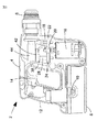
図1を参照すると、当業者に理解可能なように、参照符号2によって概して示されるハンマードリルは、耐久プラスチック材からなるクラムシェル半体から形成されるハウジング4を有する。このハウジング4の前端から、ツールビットを把持するチャック6あるいはそれと同様の器具が延びる。また、ハウジングの底部には、充電バッテリーパック8が着脱可能に取り付けられ、この充電バッテリーパックは、充電のためには、クリップ10を押し下げて充電バッテリーパックを解放することによってハウジングから取り外し可能である。また、ハウジング4は、ハウジング内に配置される電気モーター16によってハンマードリルを駆動するトリガースイッチ14を備えるハンドル部12を有する。また、電気モーター16からは、出力シャフト18が延びており、この出力シャフト18は、そこに形成されたピニオン20を有する。ピニオン20は、その外面に形成された複数の歯(図示略)を有する。
Referring to FIG. 1, a hammer drill, generally indicated by
図1、図2、および、図4を参照すると、出力シャフト18のピニオン20は、第一のギア22と第二のギア24とに噛合する。結果として、出力シャフト18が駆動せしめられて回転するとき、ギア22とギア24も回転する。また、ギア22には、該ギア22と共に回転するように第一の駆動シャフト26が固定されており、ギア24には、該ギア24と共に回転するように第二の駆動シャフト28が固定されている。
With reference to FIGS. 1, 2, and 4, the
次に、図2および図4を参照して、ハンマードリル2のロータリーモードの動作を説明する。
Next, the operation of the rotary mode of the
電気モーター16が作動せしめられると、駆動シャフト18が回転してピニオン20を回転させる。ピニオン20は、第一のギア22と、ベアリング30によって支持されている第一の駆動シャフト26とを駆動する。第一の駆動シャフト26の上端には、該第一の駆動シャフト26と共に回転するように第一のベベルギア32が取り付けられている。一方、ドリルビット(図示略)を受容するスピンドル36に、第二のベベルギア34が取り付けられており、スピンドル36は、ハウジング内で軸線37回りに回動可能に取り付けられている。ベベルギア32、34は、互いに噛合し、第一のベベルギア32の回転が第二のベベルギア34を軸線37回りで回転せしめる。これにより、ドリルで穴を開ける働きが提供される。
When the
次に、図2、図4、および、図5を参照して、ハンマードリル2のハンマーモードについて説明する。
Next, the hammer mode of the
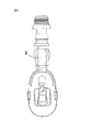
電気モーター16がトリガースイッチ14によって駆動せしめられると、電気モーターの出力シャフト18がピニオン20と共に回転する。ピニオン20は、第二のギア24の歯(図示略)と噛合する歯(図示略)を有する。結果として、駆動シャフト28に取り付けられている第二のギア24が回転する。そして、駆動シャフト28の先端には、偏心して配置されたクランクピン40(図4参照)を有するクランクプレート38が取り付けられている。また、クランクピン40および中空ピストン44の底面には、クランクアーム42が枢動可能に接続されている。中空ピストン44は、内部穴46(図5参照)を有し、案内ロッド48、50にスライド可能に取り付けられる。その結果、第二の駆動シャフト28とクランクプレート38とが回転したとき、クランクピン40の偏心運動がクランクアーム42を駆動し、クランクアーム42と中空ピストン44の底面との間の枢動可能な接続のため、中空ピストンは、案内ロッド48、50に沿って前後に往復動せしめられる。
When the
中空ピストン44の穴46内には、ラム部材52がスライド可能に配置されており、このラム部材52と中空ピストン44の内面との間には、Oリング53(図5参照)が配置されている。ラム部材52は、中空ピストン44の内側にシールされているので、中空ピストン44が往復動したとき、ラム部材52は、空気バネ作用下で中空ピストン44に対して振動する。また、ラム部材は、スピンドル36内へと進入する前端54を有する。ラム部材52が振動すると、ラム部材52の前端54は、ツールビット(図示略)の後部を叩いて、ハンマードリルのハンマー動作を提供する。
A
ユーザーは、モード変更機構(図示略)によって、ハンマーモードと、ロータリーモードと、ハンマーモードとロータリーモードとの組合せのうち一つ選択することができる。例えば、ハンマーモードは、ギア22をピニオン20から解放することで選択される。また、ロータリーモードは、ギア24をピニオン20から解放することで選択される。一方、ハンマーモードとロータリーモードとの組合せは、両ギア22、24がピニオン20に係合した状態にあるときに選択される。
The user can select one of a hammer mode, a rotary mode, and a combination of the hammer mode and the rotary mode by a mode change mechanism (not shown). For example, the hammer mode is selected by releasing the
中空ピストン44の底面に係合するクランクピン40と共に案内ロッド48、50にスライド可能に取り付けられる中空ピストン44を提供することによって、ハンマードリルを従来よりも大幅に小型な構造にすることが可能である。
By providing a
上述した実施形態は、例示のみを目的として説明したものであって、いかなる制限する意図はなく、種々の変更や改良が、特許請求の範囲によって定義される本発明の範囲から逸脱することなく可能であることは当業者にとって明らかであろう。 The above-described embodiments have been described by way of example only and are not intended to be limiting in any way, and various modifications and improvements can be made without departing from the scope of the invention as defined by the claims. It will be apparent to those skilled in the art.
2 ハンマードリル
4 ハウジング
6 チャック
8 充電バッテリーパック
10 クリップ
12 ハンドル部
14 トリガースイッチ
16 電気モーター
18 出力シャフト
20 ピニオン
22、24 ギア
26、28 駆動シャフト
30 ベアリング
32、34 ベベルギア
36 スピンドル
37 軸線
38 クランクプレート
40 クランクピン
42 クランクアーム
44 中空ピストン
46 穴
48、50 案内ロッド
52 ラム部材
53 Oリング
54 前端
2
Claims (11)
Applications Claiming Priority (2)
| Application Number | Priority Date | Filing Date | Title |
|---|---|---|---|
| GB0428215A GB0428215D0 (en) | 2004-12-23 | 2004-12-23 | Piston Drive Mechanism |
| GB0516506A GB2421465A (en) | 2004-12-23 | 2005-08-11 | Hammer mechanism for a power tool |
Publications (1)
| Publication Number | Publication Date |
|---|---|
| JP2006175584A true JP2006175584A (en) | 2006-07-06 |
Family
ID=36046957
Family Applications (1)
| Application Number | Title | Priority Date | Filing Date |
|---|---|---|---|
| JP2005327276A Pending JP2006175584A (en) | 2004-12-23 | 2005-11-11 | Hammer mechanism for power tool |
Country Status (4)
| Country | Link |
|---|---|
| US (1) | US20060137889A1 (en) |
| EP (1) | EP1674206A1 (en) |
| JP (1) | JP2006175584A (en) |
| AU (1) | AU2005229727A1 (en) |
Families Citing this family (10)
| Publication number | Priority date | Publication date | Assignee | Title |
|---|---|---|---|---|
| EP1949992B1 (en) * | 2007-01-25 | 2010-05-26 | Metabowerke GmbH | Striking mechanism for a chisel tool or a hammer drill; chisel tool or hammer drill |
| US9016395B2 (en) * | 2010-11-16 | 2015-04-28 | Milwaukee Electric Tool Corporation | Impact tool |
| US20150174744A1 (en) * | 2010-11-16 | 2015-06-25 | Techtronic Industries Co. Ltd. | Impact tool |
| US9630307B2 (en) | 2012-08-22 | 2017-04-25 | Milwaukee Electric Tool Corporation | Rotary hammer |
| DE102013210391A1 (en) * | 2013-06-05 | 2014-12-11 | Robert Bosch Gmbh | power tool |
| EP2937185A1 (en) * | 2014-04-22 | 2015-10-28 | HILTI Aktiengesellschaft | Manual machine tool |
| GB201421577D0 (en) * | 2014-12-04 | 2015-01-21 | Black & Decker Inc | Drill |
| GB201421576D0 (en) | 2014-12-04 | 2015-01-21 | Black & Decker Inc | Drill |
| DE102015226448A1 (en) * | 2015-12-22 | 2017-06-22 | Robert Bosch Gmbh | Portable machine tool and method of making a portable machine tool |
| USD921072S1 (en) * | 2017-11-22 | 2021-06-01 | Kjell Andersson | Core drill attachment |
Citations (3)
| Publication number | Priority date | Publication date | Assignee | Title |
|---|---|---|---|---|
| JPS62264879A (en) * | 1986-05-14 | 1987-11-17 | 芝浦メカトロニクス株式会社 | Impact tool |
| JPS6426176A (en) * | 1987-04-20 | 1989-01-27 | Hazeltine Corp | Automatic and real time disturbance monitoring/checking circuit network for microwave landing system |
| EP0775556A1 (en) * | 1995-11-27 | 1997-05-28 | Black & Decker Inc. | Hammer mechanism |
Family Cites Families (33)
| Publication number | Priority date | Publication date | Assignee | Title |
|---|---|---|---|---|
| US1740701A (en) * | 1921-10-17 | 1929-12-24 | Sullivan Machinery Co | Drilling mechanism |
| GB969007A (en) * | 1960-03-30 | 1964-09-09 | Skil Corp | Rotary hammer device |
| US3191694A (en) * | 1962-03-05 | 1965-06-29 | John Lynn & Co Ltd | Percussive tools |
| GB1030136A (en) * | 1963-10-23 | 1966-05-18 | Kango Electric Hammers Ltd | Improvements relating to power-operated percussive tools |
| US3583619A (en) * | 1968-10-31 | 1971-06-08 | Donald O Shepherd | Yarn accumulator |
| DE1938660C3 (en) * | 1969-07-30 | 1975-05-15 | Metabowerke Kg, Closs, Rauch & Schnizler, 7440 Nuertingen | Hammer drill |
| DE1964083C3 (en) * | 1969-12-22 | 1983-01-27 | Robert Bosch Gmbh, 7000 Stuttgart | Rock drilling machine |
| US3921729A (en) * | 1971-11-25 | 1975-11-25 | Hilti Ag | Electropneumatic hammer |
| US3834469A (en) * | 1972-11-14 | 1974-09-10 | Wacker Werke Kg | Internal combustion operated hammer |
| US4014392A (en) * | 1973-03-01 | 1977-03-29 | Ross Frederick W | Stabilized piston-cylinder impact device |
| DE2449191C2 (en) * | 1974-10-16 | 1988-03-24 | Robert Bosch Gmbh, 7000 Stuttgart | hammer |
| NL7504371A (en) * | 1975-04-11 | 1976-10-13 | Kooten Bv V | HEIHAMER. |
| US4340120A (en) * | 1978-03-20 | 1982-07-20 | Hawk Industries, Inc. | Annular casing hammer |
| GB2038986B (en) * | 1978-12-13 | 1983-05-05 | Black & Decker Inc | Converting rotary motion to reciprocatory motion |
| US4436163A (en) * | 1978-12-13 | 1984-03-13 | Black & Decker Inc. | Arrangement for converting rotary motion to reciprocatory motion |
| US4370916A (en) * | 1979-10-04 | 1983-02-01 | Mitin Leonid A | Percussive device |
| US4285550A (en) * | 1979-10-15 | 1981-08-25 | Blackburn Robert V | Weight transfer roller apparatus |
| US4382637A (en) * | 1979-10-15 | 1983-05-10 | Blackburn Robert V | Weight transfer roller apparatus |
| SE433907B (en) * | 1980-05-30 | 1984-06-25 | Duni Bila Ab | PRE-FITTING DYNA |
| ATE11750T1 (en) * | 1980-11-18 | 1985-02-15 | Black & Decker Inc. | IMPACT DRILL. |
| DE3304916A1 (en) * | 1983-02-12 | 1984-08-16 | Robert Bosch Gmbh, 7000 Stuttgart | DRILLING HAMMER |
| DE3590888T1 (en) * | 1985-12-23 | 1988-03-10 | ||
| GB9124016D0 (en) * | 1991-11-12 | 1992-01-02 | Johnson Electric Sa | An angularly biassed self-aligning bearing |
| DE4207295A1 (en) * | 1992-03-07 | 1993-09-09 | Black & Decker Inc | DRILLING HAMMER |
| US5320177A (en) * | 1992-03-30 | 1994-06-14 | Makita Corporation | Power driven hammer drill |
| DE4239294A1 (en) * | 1992-11-23 | 1994-05-26 | Black & Decker Inc | Hammer drill with pneumatic hammer mechanism |
| JP3062436B2 (en) * | 1996-07-09 | 2000-07-10 | 株式会社ユニクラ | Swash plate compressor |
| DE19717712A1 (en) * | 1997-04-18 | 1998-10-22 | Black & Decker Inc | Hammer drill |
| US6257767B1 (en) * | 1999-08-27 | 2001-07-10 | Emerson Electric Co. | Reduced cost bearing retainer |
| US6648511B2 (en) * | 2000-07-10 | 2003-11-18 | Fasco Industries, Inc. | Electric motor bearing system and journal |
| GB0109747D0 (en) * | 2001-04-20 | 2001-06-13 | Black & Decker Inc | Hammer |
| DE10121088A1 (en) * | 2001-04-28 | 2002-11-07 | Bosch Gmbh Robert | Hammer drill and / or chisel hammer |
| GB0213464D0 (en) * | 2002-06-12 | 2002-07-24 | Black & Decker Inc | Hammer |
-
2005
- 2005-10-21 EP EP05022982A patent/EP1674206A1/en not_active Withdrawn
- 2005-11-04 AU AU2005229727A patent/AU2005229727A1/en not_active Abandoned
- 2005-11-11 JP JP2005327276A patent/JP2006175584A/en active Pending
- 2005-12-21 US US11/314,523 patent/US20060137889A1/en not_active Abandoned
Patent Citations (3)
| Publication number | Priority date | Publication date | Assignee | Title |
|---|---|---|---|---|
| JPS62264879A (en) * | 1986-05-14 | 1987-11-17 | 芝浦メカトロニクス株式会社 | Impact tool |
| JPS6426176A (en) * | 1987-04-20 | 1989-01-27 | Hazeltine Corp | Automatic and real time disturbance monitoring/checking circuit network for microwave landing system |
| EP0775556A1 (en) * | 1995-11-27 | 1997-05-28 | Black & Decker Inc. | Hammer mechanism |
Also Published As
| Publication number | Publication date |
|---|---|
| EP1674206A1 (en) | 2006-06-28 |
| AU2005229727A1 (en) | 2006-07-13 |
| US20060137889A1 (en) | 2006-06-29 |
Similar Documents
| Publication | Publication Date | Title |
|---|---|---|
| JP2006175584A (en) | Hammer mechanism for power tool | |
| US7350592B2 (en) | Hammer drill with camming hammer drive mechanism | |
| JP6367617B2 (en) | Reciprocating work tool | |
| JP5345893B2 (en) | Impact tool | |
| EP1477280A3 (en) | Rotary hammer | |
| JP5294726B2 (en) | Hand-held work tool | |
| EP1690646A1 (en) | Hand-held hammer machine | |
| CN106166729B (en) | Working tool | |
| US7398835B2 (en) | Rotary hammer having both a reciprocating hammer mechanism and a ratcheting hammer mechanism | |
| US6739405B2 (en) | Hammer | |
| US10518400B2 (en) | Work tool | |
| ATE294674T1 (en) | PITCH HAMMER | |
| US11571796B2 (en) | Rotary hammer | |
| GB2421465A (en) | Hammer mechanism for a power tool | |
| WO2015045734A1 (en) | Impact tool | |
| WO2012144568A1 (en) | Impact tool | |
| JP7412135B2 (en) | impact tool | |
| JP5913010B2 (en) | Impact tool | |
| WO2014142112A1 (en) | Impact tool | |
| JP2012171063A (en) | Impact tool | |
| JP2006198718A (en) | Punching machine |
Legal Events
| Date | Code | Title | Description |
|---|---|---|---|
| A621 | Written request for application examination |
Free format text: JAPANESE INTERMEDIATE CODE: A621 Effective date: 20080820 |
|
| A131 | Notification of reasons for refusal |
Free format text: JAPANESE INTERMEDIATE CODE: A131 Effective date: 20110628 |
|
| A02 | Decision of refusal |
Free format text: JAPANESE INTERMEDIATE CODE: A02 Effective date: 20111206 |