JP2006166183A - Ultrasonic vibrator and flow measurement apparatus of fluid using the same - Google Patents
Ultrasonic vibrator and flow measurement apparatus of fluid using the same Download PDFInfo
- Publication number
- JP2006166183A JP2006166183A JP2004356355A JP2004356355A JP2006166183A JP 2006166183 A JP2006166183 A JP 2006166183A JP 2004356355 A JP2004356355 A JP 2004356355A JP 2004356355 A JP2004356355 A JP 2004356355A JP 2006166183 A JP2006166183 A JP 2006166183A
- Authority
- JP
- Japan
- Prior art keywords
- matching layer
- ultrasonic transducer
- layer
- organic glass
- case
- Prior art date
- Legal status (The legal status is an assumption and is not a legal conclusion. Google has not performed a legal analysis and makes no representation as to the accuracy of the status listed.)
- Pending
Links
Images


Abstract
Description
本発明は、例えば、流体の流量を計測する超音波流れ計測装置などに用いる超音波振動子に関するものである。 The present invention relates to an ultrasonic transducer used in, for example, an ultrasonic flow measurement device that measures the flow rate of a fluid.
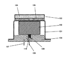
従来、この種の超音波振動子は、図5に示すように、導電性のキャップ状のケース101の頂壁内面に正方柱状の圧電体102を、頂壁外面に音響整合層103をそれぞれ接着剤で固定し、またケース101の下方開放部には同じく導電性の台座104が溶接などの手段で固定されている。
Conventionally, as shown in FIG. 5, this type of ultrasonic transducer has a square pillar-shaped
音響整合層103は第1層となるセラミック多孔体105、および第2層となる多孔性の有機ガラスの乾燥ゲル106との2層構成にしてある。
The
圧電体102の上面電極はケース101、台座104を介して端子107に、下面電極は導電性ゴム108を介して端子109にそれぞれ接続してある。なお、端子109は封入ガラス部110により台座104と絶縁されている(例えば、特許文献1参照)。
このような構成の従来の超音波振動子において、音響整合層103を構成する多孔性の有機ガラスの乾燥ゲル106とセラミック多孔体105の一部部分を連続して構成していたため、製造時の蒸発乾燥あるいは熱サイクルなどの温度変化により、熱膨張係数の違いによると思われる歪みにより、強度的に弱い有機ガラスの乾燥ゲル106にクラックなどのひび割れや、表面層の剥離などが発生し、信頼性、特に長期信頼性に課題を有していた。
In the conventional ultrasonic vibrator having such a configuration, a part of the porous organic glass
本発明は、前記従来の課題を解決するもので、有機ガラスの乾燥ゲルで構成される第2整合層のひび割れなどを防止して超音波振動子の動作的信頼性を高めたことを目的とするものである。 An object of the present invention is to solve the above-mentioned conventional problems, and to improve the operational reliability of an ultrasonic transducer by preventing cracks and the like of a second matching layer composed of a dried gel of organic glass. To do.
前記従来の課題を解決するために、本発明の超音波振動子は、キャップ状のケース内に接着された圧電体と、セラミック多孔体よりなる第1整合層、有機ガラスの乾燥ゲルからなる第2整合層を前記ケースの表面に接着層を介して順次積層して構成した音響整合層とを具備したもので、セラミック多孔体と有機ガラスの乾燥ゲルとの熱膨張係数の違いによる歪みの発生を抑制することができ、長期信頼性に優れた超音波振動子を提供することができる。 In order to solve the above-described conventional problems, an ultrasonic transducer according to the present invention includes a piezoelectric body bonded in a cap-shaped case, a first matching layer made of a ceramic porous body, and a first organic glass dry gel. The acoustic matching layer is formed by sequentially laminating two matching layers on the surface of the case via an adhesive layer, and distortion occurs due to a difference in thermal expansion coefficient between the ceramic porous body and the organic glass dry gel. Can be suppressed, and an ultrasonic transducer having excellent long-term reliability can be provided.
本発明の超音波振動子は、2層からなる音響整合層を柔軟性のある接着層を介して積層しているので、強度的に弱い有機ガラスの乾燥ゲルにクラックなどのひび割れや、表面層の剥離などを発生することなく、長期信頼性を確保することができる。 In the ultrasonic transducer of the present invention, since the acoustic matching layer composed of two layers is laminated via a flexible adhesive layer, cracks such as cracks in the dry gel of organic glass that is weak in strength, and the surface layer Long-term reliability can be ensured without causing peeling.
第1の発明は、キャップ状のケース内に接着された圧電体と、セラミック多孔体よりなる第1整合層、有機ガラスの乾燥ゲルからなる第2整合層を前記ケースの表面に接着層を介して順次積層して構成した音響整合層とを具備したもので、前記第1層と第2層との熱膨張係数の差による歪みが接着層で緩和され、比較的強度の弱い有機ガラスの乾燥ゲルにクラックなどのひび割れや、表面層の剥離などが発生するのを防ぐができる。 According to a first aspect of the present invention, a piezoelectric body bonded in a cap-shaped case, a first matching layer made of a ceramic porous body, and a second matching layer made of a dried gel of organic glass are disposed on the surface of the case via an adhesive layer. And an acoustic matching layer formed by sequentially laminating, and the strain due to the difference in thermal expansion coefficient between the first layer and the second layer is relaxed by the adhesive layer, and the organic glass having a relatively low strength is dried. It is possible to prevent the gel from cracking such as cracks and peeling of the surface layer.
第2の発明は、特に第1の発明の、第1整合層を凹状とするとともに、その凹状空間に第2整合層を配置したことにより、比較的強度の弱い第2の層を、第1の層で保護することができ、作業性や加工性が向上し、特性のそろった超音波振動子を提供できる。 According to the second invention, the first matching layer of the first invention is made concave, and the second matching layer is disposed in the concave space, so that the second layer having relatively low strength is Therefore, it is possible to provide an ultrasonic transducer with uniform characteristics, with improved workability and workability.
第3の発明は、特に第1または第2の発明の、第1整合層を構成するセラミック多孔体の内部に、前記第2整合層を構成する有機ガラスの乾燥ゲルを形成することにより、セラミック多孔体の内部に水などの浸入が無くなり、信頼性を高くすることができる。 According to a third aspect of the present invention, there is provided a ceramic by forming a dried gel of an organic glass constituting the second matching layer inside the ceramic porous body constituting the first matching layer, particularly of the first or second invention. There is no intrusion of water or the like inside the porous body, and the reliability can be increased.
第4の発明は、特に第3の発明の、有機ガラスの乾燥ゲルを疎水化処理することにより、整合層内部に水蒸気などの浸入がなくなり、信頼性を高くすることができる。 In the fourth aspect of the invention, in particular, the organic gel dry gel of the third aspect is subjected to a hydrophobization treatment, so that intrusion of water vapor or the like does not occur in the matching layer, and the reliability can be increased.
第5の発明は、特に第1の発明の、ケースと圧電体および前記ケースと第1整合層とをエポキシ系接着層で構成することにより、比較的強度の大きいセラミック多孔体を強固にケースの固着できるので、熱によりケースの変形をある程度抑制することができ、比較的強度の弱い有機ガラスの乾燥ゲル表面にヒビ割れや剥離などの発生を抑え、信頼性の高い超音波振動子を提供できる。 According to a fifth aspect of the invention, in particular, the case and the piezoelectric body and the case and the first matching layer of the first aspect are configured by an epoxy-based adhesive layer, so that a relatively strong ceramic porous body can be firmly Because it can be fixed, the deformation of the case can be suppressed to some extent by heat, and the generation of cracks and peeling on the dry gel surface of organic glass with relatively low strength can be suppressed, and a highly reliable ultrasonic transducer can be provided. .
第6の発明は、特に第1の発明の、第1整合層と、前記第2整合層とをエラストマー系の接着層で構成することにより、缶ケースあるいはセラミック多孔体の熱などにより発生する歪みが、第2整合層へ伝わるのを緩和することができ、比較的強度の弱い第2整合層の表面にヒビ割れや剥離などの発生を抑え、信頼性の高い超音波振動子を提供できる。 The sixth aspect of the invention is the distortion generated by the heat of the can case or the ceramic porous body, in particular, by configuring the first matching layer and the second matching layer of the first invention with an elastomeric adhesive layer. However, the propagation to the second matching layer can be mitigated, and the occurrence of cracks and delamination on the surface of the second matching layer having a relatively low strength can be suppressed, and a highly reliable ultrasonic transducer can be provided.
第7の発明は、特に第1の発明の、第2整合層の表面をエラストマー系材料で被覆した構成とすることにより、比較的強度の弱い第2整合層を構成する有機ガラスの乾燥ゲル表面にヒビ割れや剥離などが発生しても、表面前面に拡大することを抑制するので、感度変化の小さい、信頼性の高い超音波振動子を提供できる。 The seventh invention is a dry gel surface of organic glass that constitutes the second matching layer having a relatively low strength, particularly by adopting a configuration in which the surface of the second matching layer of the first invention is coated with an elastomeric material. Even if cracking, peeling, etc. occur, the expansion to the front surface of the surface is suppressed, so that it is possible to provide a highly reliable ultrasonic vibrator with small sensitivity change.
第8の発明は、特に第7発明の前記被覆層の厚さを10ミクロン以下とする構成としたので、被覆層を設けたことによる大きな感度変化を抑えることができ、生産性を低下させることなく超音波振振動子を提供することができる。 In the eighth invention, since the thickness of the coating layer of the seventh invention is set to 10 microns or less, it is possible to suppress a large change in sensitivity due to the provision of the coating layer and to reduce productivity. And an ultrasonic vibrator can be provided.
第9の発明は、前記超音波振動子を流体の流れ方向に間隔をおいて少なくとも1対配置して流体の流れ測定装置としたもので、流体の流速およびまたはその流速にもとにした流量計測の高精度化を図ったものである。 According to a ninth aspect of the present invention, there is provided a fluid flow measuring device in which at least one pair of the ultrasonic transducers are arranged at intervals in the fluid flow direction, and the flow rate of the fluid and / or the flow rate based on the flow rate is determined. This is to improve the accuracy of measurement.
以下、本発明の実施の形態について図面を参照しながら説明する。なお、この実施の形態によって本発明が限定されるものではない。 Hereinafter, embodiments of the present invention will be described with reference to the drawings. Note that the present invention is not limited to the embodiments.
(実施の形態1)
図1は、本発明の実施の形態1における超音波振動子を示し、超音波振動子1は、導電性材料からなるキャップ状のケース2の頂壁内面にエポキシ樹脂などで接着された圧電体3と、頂壁外面に接着された音響整合層4とから構成されている。
(Embodiment 1)
FIG. 1 shows an ultrasonic transducer according to Embodiment 1 of the present invention. The ultrasonic transducer 1 is a piezoelectric body bonded to the inner surface of the top wall of a cap-
前記音響整合層4は、セラミック多孔体からなる第1の整合層5と、有機ガラスの乾燥ゲルからなる第2の整合層6との2層構成とした。セラミック多孔体からなる第1の整合層5の外径は12mm、板厚は1.5mmとした。また、有機ガラスの乾燥ゲルからなる第2の整合層6は外径12mm、厚さ0.5mmとした。
The acoustic matching layer 4 has a two-layer structure including a first matching
なお、圧電体3は約7.4mm角の角柱状とし、その上面、下面には焼き付け銀などで構成される電極が形成されている(図示せず)。また、導電性の台座7はケース2の下方開放部を閉塞するもので、その周辺部が溶接され、圧電体3を密封する構成とした。
The
導電性のゴム8は圧電体3の下面電極と端子9とを電気的に接続している。一方の端子9は、ハーメチックシールなどの絶縁性材料10により台座7に絶縁固定された状態で導電性のゴム8に導通され、他方の端子11は、導電性の台座7に直接固定され、ケース2を介して圧電体3の上面電極に接続されている。
The
なお、ケース2とセラミック多孔体からなる第1の整合層5とはエポキシ系接着剤を用いて接着固定した。
The
そして、第1整合層5と第2整合層6とは粘着性のある、例えばシリコンゴムなどの接着剤を介して接着固定してある。
The first matching
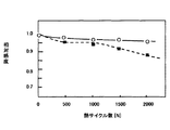
この構成により、熱サイクル試験を実施しても、第2整合層6の表面にクラックや剥離などが観側されなかった。このため、大きな感度低下を示すことがなかった。図2に熱サイクル試験の結果を示す。
With this configuration, even when the thermal cycle test was performed, no cracks or peeling were observed on the surface of the second matching
同図において、横軸は熱サイクル試験におけるサイクル数を、縦軸に開始時を1.0とする超音波振動子の相対感度を示す。熱サイクル試験は、+80℃とー40℃の気相間に30分間交互に保持する方法とした。図中の白丸は本実施の形態に基づく超音波振動子の結果(N=10個の平均)を、黒四角は従来の超音波振動子の結果(N=10個の平均)を示す。 In the figure, the horizontal axis represents the number of cycles in the thermal cycle test, and the vertical axis represents the relative sensitivity of the ultrasonic transducer with 1.0 at the start. The thermal cycle test was a method of alternately holding between + 80 ° C. and −40 ° C. for 30 minutes. The white circles in the figure indicate the results (N = 10 averages) of the ultrasonic transducers based on the present embodiment, and the black squares indicate the results of the conventional ultrasonic transducers (N = 10 averages).
本実施の形態に基づく超音波振動子では、熱サイクル2000回においても感度低下は5%以下であり、実用上問題となる10%以上感度低下するものはなかった。従来の超音波振動子では1500回以降に劣化するものが多く見られ、2000回では実用上問題となる10%以上の感度低下が発生した。 In the ultrasonic transducer according to the present embodiment, the decrease in sensitivity was 5% or less even after 2000 thermal cycles, and there was no decrease in sensitivity of 10% or more, which was a practical problem. Many conventional ultrasonic transducers deteriorate after 1500 times. At 2000 times, a sensitivity drop of 10% or more, which is a practical problem, occurred.
なお、本実施の形態に基づく超音波振動子の表面にも数個以内のクラックが散見されたが、感度低下につながるものではなかった。また、表面の剥離が観側されたものは皆無であった。従来の超音波振動子では、クラックが多く認められ、表面の剥離にいたるものも多数あり、感度低下となって観測された。 Although several cracks were found on the surface of the ultrasonic transducer based on the present embodiment, the sensitivity was not lowered. In addition, none of the surfaces were peeled off. In conventional ultrasonic vibrators, many cracks were observed, and there were many that led to surface peeling, which was observed as a decrease in sensitivity.
(実施の形態2)
図3は、第2の実施の形態における音響整合層14を示す。セラミック多孔体からなる第1の整合層15は凹状に構成され、その内部に比較的強度の弱い有機ガラスの乾燥ゲルからなる第2の整合層16が充填形成されている。なお、第1,第2の整合層15,16は、実施の形態1と同様に、粘着性のある、例えばシリコンゴムなどの接着剤を介して接着固定した。また、図示はしていないが、第1の整合層15はエポキシ系接着剤を介してケースに接着固定した。
(Embodiment 2)
FIG. 3 shows the acoustic
実施の形態1で示した熱サイクル試験にかけたところ、同様の効果が得られた。また、この構成により、接着工程などの作業性が大幅に改善され、生産性が大幅に向上した。すなわち、比較的強度の大きい凹状のセラミック多孔体からなる第1の整合層15が比較的強度の弱い有機ガラスの乾燥ゲルからなる第2の整合層16を保護する形となり、作業中の有機乾燥ゲルが欠けるなどのことがなくなった。
When subjected to the thermal cycle test shown in the first embodiment, the same effect was obtained. In addition, this configuration greatly improved workability such as the bonding process, and greatly improved productivity. That is, the
(実施の形態3)
前記実施の形態1および実施の形態2において示した第1の整合層5,15の内部、すなわち、セラミック多孔体の気孔部に、予め第2整合層6,16として用いる有機ガラスの乾燥ゲルを含浸させ、第1整合層として用いた。この構成により、第1の整合層5,15であるセラミック多孔体の内部、気孔部分に水などの液体が浸入し、液化したりすることがなくなった。このため、長期信頼性の高い超音波振動子を実現することができた。
(Embodiment 3)
A dry gel of organic glass used in advance as the second matching layers 6 and 16 in the first matching layers 5 and 15 shown in the first and second embodiments, that is, in the pores of the ceramic porous body. Impregnated and used as the first matching layer. With this configuration, liquid such as water does not enter the pores of the ceramic porous body that is the first matching layers 5 and 15 and liquefy. For this reason, an ultrasonic vibrator with high long-term reliability could be realized.
(実施の形態4)
実施の形態3に示した有機ガラスの乾燥ゲル内部を疎水化処理し、音響整合層として用いた。この構成により、水蒸気などが音響整合層内部に侵入し、結露、あるいは水滴となって滞留することがなくなり、超音波感度が低下するなどの不具合はなくなり、長期信頼性が向上した。
(Embodiment 4)
The inside of the dry gel of the organic glass shown in
(実施の形態5)
第1,2整合層、およびケースそれぞれの間に介在する接着層について実施の形態1を例にとって以下に説明する。
(Embodiment 5)
The first and second matching layers and the adhesive layer interposed between the cases will be described below by taking Embodiment 1 as an example.
第1整合層5とケース2との間の接着層はエポキシ系接着層とした。すなわち、強固に接着するエポキし系を選択した。
The adhesive layer between the
この構成により、ケース2と第1整合層5であるセラミック多孔体の熱膨張係数の差に起因する熱応力は、熱変形の少ない第1整合層5が熱膨張係数の大きいケース2の熱変形を抑えるように働く。
With this configuration, the thermal stress caused by the difference in the thermal expansion coefficient between the
また、第1,2整合層5,6の間に介在する接着層は、シリコンゴムあるいはフッ素ゴムなどの粘着力のある接着剤で構成した。この構成により、ケース2で発生し、第1整合層5を介して第2整合層6に伝達される熱応力は、粘着力のある接着層を介して伝達されるため、大きく緩和される結果となった。
The adhesive layer interposed between the first and second matching layers 5 and 6 is made of an adhesive having adhesive strength such as silicon rubber or fluorine rubber. With this configuration, the thermal stress generated in the
したがって、実施の形態1で示したように、熱サイクル試験を2000回実施しても第2整合層6の表面にクラック、剥離の発生はなかった。なお、第1整合層5と第2整合層6とをエポキシ系接着剤で強固に接着した場合には、第2整合層6の表面に多数のクラックが確認された。これは、エポキシ系接着剤は硬化すると柔軟性が無くなり、ケース2で発生した熱応力が第1整合層5を伝わり、その応力が緩和されることなく第2整合層6に伝達されるためと考えられる。
Therefore, as shown in the first embodiment, no cracks or peeling occurred on the surface of the
したがって、ケース2と第1整合層5との間の接着層は、強固な接着層を形成するエポキシ系接着剤がケース2で発生する熱応力を熱変形の小さい第1整合層5により抑制することになるので適している。また、第1整合層5と第2整合層6との間の接着層は、柔軟性のあるシリコンゴムなどのエラストマー系接着剤がケース2で発生する熱応力を緩和する方向に働くので、適している。
Therefore, the adhesive layer between the
(実施の形態6)
図4は、実施の形態6における音響整合層24を示す。セラミック多孔体からなる第1の整合層25は凹状に構成され、その内部に比較的強度の弱い有機ガラスの乾燥ゲルからなる第2の整合層26が充填形成されている。なお、第1,第2の整合層25,26は、実施の形態1と同様に、粘着性のある、例えばシリコンゴムなどの接着剤を介して接着固定した。また、図示はしていないが、第1の整合層25はエポキシ系接着剤を介してケースに接着固定した。
そして、音響整合層24の表面および周囲がエラストマー系接着剤27で被覆してある。
(Embodiment 6)
FIG. 4 shows the
The surface and the periphery of the
この構成により、第2整合層16にたとえクラックが入った場合でも、エラストマー系接着剤27で被覆されているため、クッラクが伝播しにくく、そのためクラックが広がることがない。
With this configuration, even if the
また、例え第2整合層27の一部が剥離状態となっても、表面がエラストマー系接着剤27で被覆されているため、剥離し脱落することがない。このため、感度低下が著しく抑制される結果となった。
Even if a part of the
(実施の形態7)
次に、超音波振動子の製造方法について説明する。
(Embodiment 7)
Next, a method for manufacturing the ultrasonic transducer will be described.
まず、有機ガラスの乾燥ゲルを準備する。 First, an organic glass dry gel is prepared.
音響整合層としての有機ガラスの乾燥ゲルとしては、音速が小さく、密度の低いことが要求される。エトキシシランあるいはメトキシシランなどの有機溶液からなるガラス原料を、塩酸系触媒を用い十分活性な状態で、メチルあるいはエチルなどのアルコール系溶媒に分散させる。 The organic glass dry gel as the acoustic matching layer is required to have a low sound speed and a low density. A glass raw material made of an organic solution such as ethoxysilane or methoxysilane is dispersed in an alcohol solvent such as methyl or ethyl in a sufficiently active state using a hydrochloric acid catalyst.
この分散された溶液をアンモニア水などの塩基性触媒を添加するとともに、テフロン(登録商標)などの反応しない材料で作成された型枠に流し込み、成形する。この状態で、40〜50℃、3〜6時間保持すると湿潤ゲルが得られる。 The dispersed solution is added with a basic catalyst such as aqueous ammonia and poured into a mold made of a non-reactive material such as Teflon (registered trademark) to be molded. In this state, a wet gel is obtained when held at 40 to 50 ° C. for 3 to 6 hours.
この湿潤ゲルを再度、エトキシシランあるいはメトキシシランなどの原料溶液とアンモニアなどの塩基性触媒とを用い再度有機ガラスを形成すると、湿潤ゲルを乾燥させても、収縮しない、すなわち、体積変化の殆どしない乾燥ゲルが得られる。 When this wet gel is formed again using a raw material solution such as ethoxysilane or methoxysilane and a basic catalyst such as ammonia, even if the wet gel is dried, it does not shrink, that is, there is almost no volume change. A dry gel is obtained.
この有機ガラスの乾燥ゲルを使用目的に応じて、疎水化処理などを施すことがある。疎水化処理は、ジメチルジエトキシシラン溶液とアンモニアなどの塩基性触媒などを用い実施した。このようにして成形された有機ガラスの乾燥ゲルを準備する。 The organic glass dry gel may be subjected to a hydrophobizing treatment or the like depending on the purpose of use. The hydrophobization treatment was performed using a dimethyldiethoxysilane solution and a basic catalyst such as ammonia. An organic glass dry gel thus formed is prepared.
次に、セラミック多孔体を準備する。この種の音響整合層を構成するセラミック多孔体について説明する。セラミック多孔体に要求される特性は、気孔率が大きく、気孔径分布が一様で、且つ、分布に偏りがないことが重要でとなる。 Next, a ceramic porous body is prepared. A ceramic porous body constituting this type of acoustic matching layer will be described. It is important that the characteristics required for the ceramic porous body are large porosity, uniform pore size distribution, and no uneven distribution.
このようなセラミック多孔体を形成するには、気泡を多く含むセラミックスラリーを固化させ、焼成するゾルキャスティグ法が適している。 In order to form such a ceramic porous body, a sol-casting method in which a ceramic slurry containing many bubbles is solidified and fired is suitable.
簡単に、ゾルキャスティング法の工程を説明する。まず、セラミック粉末原料と、架橋剤、触媒、界面活性剤などを含むゲル化材料とを十分混合する。このとき混合媒体としては水あるいは有機溶媒などを用いるとよい。このようにしてセラミックスラリーが形成される。このとき、分散剤、滑剤、増粘剤、糊剤などを添加してもよい。 The process of the sol casting method will be briefly described. First, a ceramic powder raw material and a gelling material containing a crosslinking agent, a catalyst, a surfactant and the like are sufficiently mixed. At this time, water or an organic solvent may be used as the mixing medium. A ceramic slurry is thus formed. At this time, a dispersant, a lubricant, a thickener, a paste, or the like may be added.
次に、このセラミックスラリーに気泡剤を添加し、攪拌・混合し、スラリー中に、気泡を所定量導入する。なお、気泡を導入する前には、セラミックスラリーを予め充分脱気しておくと、気泡の導入量が安定する。このようにして気泡が導入されたセラミックスラリー所定の形状となるよう型枠に入れ、成形する。乾燥後、脱型し、界面活性剤などの有機物を焼き飛ばすことにより多くの気泡を含むセラミック成型体が形成される。その後、所定の温度、時間により、セラミック成形体を焼成する。 Next, a foaming agent is added to the ceramic slurry, stirred and mixed, and a predetermined amount of foam is introduced into the slurry. If the ceramic slurry is sufficiently deaerated before introducing bubbles, the amount of bubbles introduced is stabilized. In this way, the ceramic slurry into which bubbles have been introduced is put into a mold so as to have a predetermined shape, and then molded. After drying, it is demolded and a ceramic molded body containing many bubbles is formed by burning off organic substances such as surfactants. Thereafter, the ceramic molded body is fired at a predetermined temperature and time.
このとき、セラミック粉末材料として、アルミナ系、ムライト系、ジルコニア系などの酸化物系の材料を用いると、比較的簡単に、ゾルキャスティング法により、この種のセラミック多孔体を形成することができる。 At this time, when an oxide-based material such as alumina, mullite, or zirconia is used as the ceramic powder material, this kind of ceramic porous body can be formed by a sol-casting method relatively easily.
また、炭化珪素系、窒化珪素系、窒化アルミニウム系、窒化ホウ素系、グラファイト系などの非酸化物系のセラミック材料を用いても比較的簡単に、ゾルキャスティング法により、この種のセラミック多孔体を形成することができる。さらに、非酸化物系のセラミック材料を用いると焼成前後の寸法変化が小さいため、成形性が良い。 In addition, this kind of ceramic porous body can be formed by a sol-casting method relatively easily using non-oxide ceramic materials such as silicon carbide, silicon nitride, aluminum nitride, boron nitride, and graphite. Can be formed. Furthermore, when a non-oxide ceramic material is used, the dimensional change before and after firing is small, so that formability is good.
通常の酸化物系セラミック材料の場合、焼成前後の寸法は、10〜50%前後収縮するものが多いが、非酸化物系の材料の場合、焼成において若干酸化し、体積が増加するためか、焼成前後の寸法変化が、おおよそ10%以下に収まる場合が多いので、この種の目的のセラミック多孔体として非常に適していることになる。 In the case of a normal oxide-based ceramic material, the dimensions before and after firing often shrink around 10 to 50%, but in the case of a non-oxide-based material, it is slightly oxidized during firing, and the volume increases. Since the dimensional change before and after firing often falls within approximately 10% or less, it is very suitable as a ceramic porous body of this type.
また、上記のセラミック多孔体の気泡内部に有機ガラスの乾燥ゲルを形成する方法について説明する。十分に脱気したセラミック多孔体に、上記で説明したように、エトキシシランあるいはメトキシシランなどの有機溶液からなるガラス原料を、塩酸系触媒を用い十分活性な状態で、メチルあるいはエチルなどのアルコール系溶媒に分散させた溶液をアンモニア水などの塩基性触媒を添加するとともに、充分に脱気したセラミック多孔体の気泡内部に含浸させ、熟成し、湿潤ゲルを形成する。 In addition, a method for forming a dry gel of organic glass inside the ceramic porous body will be described. As described above, a glass raw material made of an organic solution such as ethoxysilane or methoxysilane is applied to a sufficiently degassed ceramic porous body using a hydrochloric acid-based catalyst in an alcoholic state such as methyl or ethyl. A solution dispersed in a solvent is added with a basic catalyst such as aqueous ammonia and impregnated inside the bubbles of a sufficiently degassed ceramic porous body and aged to form a wet gel.
以後は、上述の工程の通り実施し、気泡内部が有機ガラスの乾燥ゲルで充満されたセラミック多孔体が得られる。 Thereafter, the process is carried out as described above to obtain a porous ceramic body in which the inside of the bubbles is filled with a dry gel of organic glass.
このようにして準備された有機ガラスの乾燥ゲル単体と、セラミック多孔体と、をシリコンゴムあるいはフッ素ゴムなどの液体状のエラストマーを用い、所定の場所に接着固定する。接着時に荷重は、1〜5Kg/平方cmとした。なお、エラストマーの接着厚さは、5〜10ミュウμmとした。 The organic glass dry gel alone prepared in this way and the ceramic porous body are bonded and fixed to a predetermined place using a liquid elastomer such as silicon rubber or fluorine rubber. The load during bonding was 1 to 5 kg / square cm. The adhesion thickness of the elastomer was 5 to 10 μm.
次に、ケース内部に圧電体がエポキシ系接着剤などで接着された振動子を準備し、ケースの上面にエポキシ系接着剤を用い、有機ガラスの乾燥ゲルが接着されたセラミック多孔体を接着した。この場合も、接着時の荷重は、1〜5Kg/平方cmとした。 Next, a vibrator having a piezoelectric body bonded with an epoxy adhesive inside the case was prepared, and an epoxy adhesive was used on the upper surface of the case, and a ceramic porous body with a dry gel of organic glass was bonded. . Also in this case, the load at the time of adhesion was set to 1 to 5 kg / square cm.
このようにして、信頼性に優れた超音波振動子を製造することができる。 In this way, an ultrasonic transducer having excellent reliability can be manufactured.
(実施の形態6)
前記超音波振動子は、例えばガスなどの流体の流れ計測に用いることができるであろう。すなわち、流体通路の上流側と下流側に少なくとも1対の超音波振動子を配置し、一方の超音波振動子から他方の超音波振動子に至る超音波伝搬時間をもとに流体の流速を測定し、必要に応じて流路の断面積および補正係数を乗じて流量を演算する。
(Embodiment 6)
The ultrasonic transducer could be used for fluid flow measurement such as gas. That is, at least one pair of ultrasonic transducers are arranged on the upstream side and the downstream side of the fluid passage, and the flow velocity of the fluid is determined based on the ultrasonic propagation time from one ultrasonic transducer to the other ultrasonic transducer. Measure and calculate the flow rate by multiplying the cross-sectional area of the flow path and the correction coefficient as necessary.
超音波伝搬形態としては、一方の超音波振動子から他方の超音波振動子に直接的に超音波を伝搬させる方式でも、或いは、一方の超音波振動子からの超音波を流路壁に反射させて他方の超音波振動子に伝搬させる方式でもよく、伝搬形式に特定されない。 As an ultrasonic wave propagation form, a method in which ultrasonic waves are directly propagated from one ultrasonic transducer to the other ultrasonic transducer, or an ultrasonic wave from one ultrasonic transducer is reflected to the flow path wall. The method of propagating to the other ultrasonic transducer may be used, and is not specified as a propagation type.
以上のように、本発明にかかる超音波振動子は、有機ガラスの乾燥ゲルとセラミック多孔体とを柔軟性のあるエラストマーで接着した音響整合層を有しているので、超音波感度が大きく、熱サイクルなどにおいても、クラックあるいは剥離などが発生しにくい、長期信頼性に優れた超音波振動子を実現することができる。 As described above, the ultrasonic transducer according to the present invention has an acoustic matching layer in which a dry gel of organic glass and a ceramic porous body are bonded with a flexible elastomer. It is possible to realize an ultrasonic vibrator excellent in long-term reliability in which cracking or peeling does not easily occur even in a thermal cycle.
従って、本発明の超音波振動子は、超音波流速・流量計などの用途にも適用できる。 Therefore, the ultrasonic transducer of the present invention can be applied to uses such as an ultrasonic flow velocity / flow meter.
1 超音波振動子
2 圧電体
4,14,24 音響整合層
5,15,25 第1の整合層
6,16,26 第2の整合層
27 エラストマー系接着層
DESCRIPTION OF SYMBOLS 1
Claims (9)
Priority Applications (1)
| Application Number | Priority Date | Filing Date | Title |
|---|---|---|---|
| JP2004356355A JP2006166183A (en) | 2004-12-09 | 2004-12-09 | Ultrasonic vibrator and flow measurement apparatus of fluid using the same |
Applications Claiming Priority (1)
| Application Number | Priority Date | Filing Date | Title |
|---|---|---|---|
| JP2004356355A JP2006166183A (en) | 2004-12-09 | 2004-12-09 | Ultrasonic vibrator and flow measurement apparatus of fluid using the same |
Publications (1)
| Publication Number | Publication Date |
|---|---|
| JP2006166183A true JP2006166183A (en) | 2006-06-22 |
Family
ID=36667663
Family Applications (1)
| Application Number | Title | Priority Date | Filing Date |
|---|---|---|---|
| JP2004356355A Pending JP2006166183A (en) | 2004-12-09 | 2004-12-09 | Ultrasonic vibrator and flow measurement apparatus of fluid using the same |
Country Status (1)
| Country | Link |
|---|---|
| JP (1) | JP2006166183A (en) |
Cited By (4)
| Publication number | Priority date | Publication date | Assignee | Title |
|---|---|---|---|---|
| JP2008147731A (en) * | 2006-12-06 | 2008-06-26 | Matsushita Electric Ind Co Ltd | Ultrasonic sensor |
| JP2008193194A (en) * | 2007-02-01 | 2008-08-21 | Matsushita Electric Ind Co Ltd | Ultrasonic oscillator and ultrasonic current meter/flowmeter |
| JP2008193290A (en) * | 2007-02-02 | 2008-08-21 | Matsushita Electric Ind Co Ltd | Acoustic matching member, ultrasonic transmitter receiver, and ultrasonic flowmeter |
| JP2019209169A (en) * | 2019-09-06 | 2019-12-12 | キヤノン株式会社 | Capacitive transducer and subject information acquisition device |
-
2004
- 2004-12-09 JP JP2004356355A patent/JP2006166183A/en active Pending
Cited By (4)
| Publication number | Priority date | Publication date | Assignee | Title |
|---|---|---|---|---|
| JP2008147731A (en) * | 2006-12-06 | 2008-06-26 | Matsushita Electric Ind Co Ltd | Ultrasonic sensor |
| JP2008193194A (en) * | 2007-02-01 | 2008-08-21 | Matsushita Electric Ind Co Ltd | Ultrasonic oscillator and ultrasonic current meter/flowmeter |
| JP2008193290A (en) * | 2007-02-02 | 2008-08-21 | Matsushita Electric Ind Co Ltd | Acoustic matching member, ultrasonic transmitter receiver, and ultrasonic flowmeter |
| JP2019209169A (en) * | 2019-09-06 | 2019-12-12 | キヤノン株式会社 | Capacitive transducer and subject information acquisition device |
Similar Documents
| Publication | Publication Date | Title |
|---|---|---|
| JP5665765B2 (en) | Ultrasonic transducer for use in fluid media | |
| Kim et al. | Flexible 1–3 composite ultrasound transducers with silver-nanowire-based stretchable electrodes | |
| JP6911013B2 (en) | Ultrasonic transducer assembly | |
| CN1458808A (en) | Sound matching part, supersonic transducer, supersonic flow meter and its producing method | |
| JP2007229327A5 (en) | ||
| US20110018387A1 (en) | Electromechanical transducer device and method of making the same | |
| CN105841800A (en) | High pressure resistant spherical hydrophone and manufacturing method thereof | |
| JP2006166183A (en) | Ultrasonic vibrator and flow measurement apparatus of fluid using the same | |
| JP2009105709A (en) | Ultrasonic transducer and ultrasonic flow measuring instrument using the same | |
| JP2008261732A (en) | Ultrasonic transmitting/receiving device and ultrasonic current flow meter | |
| US20120219760A1 (en) | Apparatus and method for providing isolation between components in microfabricated devices | |
| JP2009165931A (en) | Manufacturing method of capacitive ultrasonic transducer | |
| WO2005020631A1 (en) | Sound matching body, process for producing the same, ultrasonic sensor and ultrasonic wave transmitting/receiving system | |
| JP4080374B2 (en) | Acoustic matching member, ultrasonic transducer, ultrasonic flow meter, and manufacturing method thereof | |
| JP2008167147A (en) | Ultrasonic wave transmitter-receiver and ultrasonic wave flow meter | |
| JP2006226681A (en) | Ultrasonic vibrator, its manufacturing method and ultrasonic flowmeter | |
| JP2008193194A (en) | Ultrasonic oscillator and ultrasonic current meter/flowmeter | |
| JP2005260409A (en) | Ultrasonic oscillator, its fabrication process, and ultrasonic fluid measuring apparatus | |
| JP4983260B2 (en) | Ultrasonic transducer | |
| JP2008193292A (en) | Acoustic matching layer and ultrasonic oscillator using the same, and ultrasonic current meter/flowmeter | |
| JP2006023099A (en) | Acoustic matching layer, ultrasonic transducer using it, and ultrasonic flow measuring apparatus having ultrasonic transducer | |
| CN205949255U (en) | Compound micromechanics capacitanc ultrasonic transducer | |
| JP4321239B2 (en) | Method for manufacturing ultrasonic transducer | |
| JP2000119063A (en) | Porous dielectric sheet and piezoelectric oscillator | |
| KR20060021026A (en) | Acoustic impedance matching layer for high frequency ultrasonic transducer and method for fabricating ultrasonic transducer by using it |