JP2006158105A - Apparatus and method for cooling motor - Google Patents
Apparatus and method for cooling motor Download PDFInfo
- Publication number
- JP2006158105A JP2006158105A JP2004346024A JP2004346024A JP2006158105A JP 2006158105 A JP2006158105 A JP 2006158105A JP 2004346024 A JP2004346024 A JP 2004346024A JP 2004346024 A JP2004346024 A JP 2004346024A JP 2006158105 A JP2006158105 A JP 2006158105A
- Authority
- JP
- Japan
- Prior art keywords
- passage
- refrigerant
- rotor
- stator
- reservoir tank
- Prior art date
- Legal status (The legal status is an assumption and is not a legal conclusion. Google has not performed a legal analysis and makes no representation as to the accuracy of the status listed.)
- Granted
Links
Images


Classifications
-
- B—PERFORMING OPERATIONS; TRANSPORTING
- B60—VEHICLES IN GENERAL
- B60L—PROPULSION OF ELECTRICALLY-PROPELLED VEHICLES; SUPPLYING ELECTRIC POWER FOR AUXILIARY EQUIPMENT OF ELECTRICALLY-PROPELLED VEHICLES; ELECTRODYNAMIC BRAKE SYSTEMS FOR VEHICLES IN GENERAL; MAGNETIC SUSPENSION OR LEVITATION FOR VEHICLES; MONITORING OPERATING VARIABLES OF ELECTRICALLY-PROPELLED VEHICLES; ELECTRIC SAFETY DEVICES FOR ELECTRICALLY-PROPELLED VEHICLES
- B60L3/00—Electric devices on electrically-propelled vehicles for safety purposes; Monitoring operating variables, e.g. speed, deceleration or energy consumption
- B60L3/0023—Detecting, eliminating, remedying or compensating for drive train abnormalities, e.g. failures within the drive train
- B60L3/0061—Detecting, eliminating, remedying or compensating for drive train abnormalities, e.g. failures within the drive train relating to electrical machines
-
- B—PERFORMING OPERATIONS; TRANSPORTING
- B60—VEHICLES IN GENERAL
- B60L—PROPULSION OF ELECTRICALLY-PROPELLED VEHICLES; SUPPLYING ELECTRIC POWER FOR AUXILIARY EQUIPMENT OF ELECTRICALLY-PROPELLED VEHICLES; ELECTRODYNAMIC BRAKE SYSTEMS FOR VEHICLES IN GENERAL; MAGNETIC SUSPENSION OR LEVITATION FOR VEHICLES; MONITORING OPERATING VARIABLES OF ELECTRICALLY-PROPELLED VEHICLES; ELECTRIC SAFETY DEVICES FOR ELECTRICALLY-PROPELLED VEHICLES
- B60L2220/00—Electrical machine types; Structures or applications thereof
- B60L2220/40—Electrical machine applications
- B60L2220/46—Wheel motors, i.e. motor connected to only one wheel
-
- B—PERFORMING OPERATIONS; TRANSPORTING
- B60—VEHICLES IN GENERAL
- B60L—PROPULSION OF ELECTRICALLY-PROPELLED VEHICLES; SUPPLYING ELECTRIC POWER FOR AUXILIARY EQUIPMENT OF ELECTRICALLY-PROPELLED VEHICLES; ELECTRODYNAMIC BRAKE SYSTEMS FOR VEHICLES IN GENERAL; MAGNETIC SUSPENSION OR LEVITATION FOR VEHICLES; MONITORING OPERATING VARIABLES OF ELECTRICALLY-PROPELLED VEHICLES; ELECTRIC SAFETY DEVICES FOR ELECTRICALLY-PROPELLED VEHICLES
- B60L2220/00—Electrical machine types; Structures or applications thereof
- B60L2220/50—Structural details of electrical machines
-
- B—PERFORMING OPERATIONS; TRANSPORTING
- B60—VEHICLES IN GENERAL
- B60L—PROPULSION OF ELECTRICALLY-PROPELLED VEHICLES; SUPPLYING ELECTRIC POWER FOR AUXILIARY EQUIPMENT OF ELECTRICALLY-PROPELLED VEHICLES; ELECTRODYNAMIC BRAKE SYSTEMS FOR VEHICLES IN GENERAL; MAGNETIC SUSPENSION OR LEVITATION FOR VEHICLES; MONITORING OPERATING VARIABLES OF ELECTRICALLY-PROPELLED VEHICLES; ELECTRIC SAFETY DEVICES FOR ELECTRICALLY-PROPELLED VEHICLES
- B60L2240/00—Control parameters of input or output; Target parameters
- B60L2240/40—Drive Train control parameters
- B60L2240/42—Drive Train control parameters related to electric machines
- B60L2240/425—Temperature
-
- Y—GENERAL TAGGING OF NEW TECHNOLOGICAL DEVELOPMENTS; GENERAL TAGGING OF CROSS-SECTIONAL TECHNOLOGIES SPANNING OVER SEVERAL SECTIONS OF THE IPC; TECHNICAL SUBJECTS COVERED BY FORMER USPC CROSS-REFERENCE ART COLLECTIONS [XRACs] AND DIGESTS
- Y02—TECHNOLOGIES OR APPLICATIONS FOR MITIGATION OR ADAPTATION AGAINST CLIMATE CHANGE
- Y02T—CLIMATE CHANGE MITIGATION TECHNOLOGIES RELATED TO TRANSPORTATION
- Y02T10/00—Road transport of goods or passengers
- Y02T10/60—Other road transportation technologies with climate change mitigation effect
- Y02T10/64—Electric machine technologies in electromobility
-
- Y—GENERAL TAGGING OF NEW TECHNOLOGICAL DEVELOPMENTS; GENERAL TAGGING OF CROSS-SECTIONAL TECHNOLOGIES SPANNING OVER SEVERAL SECTIONS OF THE IPC; TECHNICAL SUBJECTS COVERED BY FORMER USPC CROSS-REFERENCE ART COLLECTIONS [XRACs] AND DIGESTS
- Y02—TECHNOLOGIES OR APPLICATIONS FOR MITIGATION OR ADAPTATION AGAINST CLIMATE CHANGE
- Y02T—CLIMATE CHANGE MITIGATION TECHNOLOGIES RELATED TO TRANSPORTATION
- Y02T90/00—Enabling technologies or technologies with a potential or indirect contribution to GHG emissions mitigation
- Y02T90/10—Technologies relating to charging of electric vehicles
- Y02T90/16—Information or communication technologies improving the operation of electric vehicles
Abstract
Description
本発明は、モータの冷却装置およびその冷却方法に関する。 The present invention relates to a motor cooling device and a cooling method thereof.
電気自動車の駆動方式の1つとして、タイヤホイールの中にモータを挿入するインホイールドライブ方式が提案されており、このインホイールドライブ方式は車室内の有効利用空間が拡大することや各輪独立駆動による従来の自動車と異なる運転感覚が得られるという特徴がある。 As an electric vehicle drive system, an in-wheel drive system in which a motor is inserted into a tire wheel has been proposed. This in-wheel drive system expands the effective use space in the vehicle interior and independently drives each wheel. It has the feature that the driving sensation different from the conventional car can be obtained.
このようなドライブシステムを実現するにはモータの小型化が必須であるが、モータ体積を小さくすると損失により発生する熱を放熱する面積も減るため、温度の上昇が顕著になり、ひいては、モータの冷却が大きな問題となる。 In order to realize such a drive system, it is essential to reduce the size of the motor. However, if the motor volume is reduced, the area that dissipates the heat generated by the loss also decreases, so the temperature rises significantly. Cooling is a big problem.
この冷却には液冷方式や空冷方式等が知られるが、液冷方式では高い冷却効率が期待できるが、タイヤホイールに取り付けられたモータに冷媒液を循環するためのポンプなどの循環装置や配管部品が必要となり、この場合、一般的にはフロントグリル近傍に冷媒液の熱交換器を設けて、この熱交換器とモータとを長い配管で繋ぐことになり、冷却システム全体が大型化してしまう。 Liquid cooling method and air cooling method are known for this cooling, but liquid cooling method can be expected to have high cooling efficiency, but circulation devices such as pumps and piping for circulating refrigerant liquid to the motor attached to the tire wheel Parts are required, and in this case, a refrigerant liquid heat exchanger is generally provided in the vicinity of the front grille, and this heat exchanger and the motor are connected by a long pipe, which increases the size of the entire cooling system. .
一方、密閉型電動圧縮機で、モータハウジングの外壁に給湯用の水を流通させるチューブを巻き付け、吸入冷媒をモータハウジング内に流通させるようにしたものがあり、この場合、冷媒を循環させるためのポンプを一体に組み付けてある(例えば、特許文献1参照)。
しかしながら、かかる従来の密閉型電動圧縮機では冷媒を循環させるポンプを一体に組み付けた場合にも、その冷媒を冷却するための給湯用チューブ内の水は外部動力で循環させる必要があり、この場合にあっても冷却システムが大型化してしまうとともに、前記冷媒の循環は一体に組付けたとはいえ、やはりポンプが必要となり、その電動圧縮機をモータに適用した場合にもモータの大型化が余儀なくされる。 However, in such a conventional hermetic electric compressor, even when a pump for circulating the refrigerant is assembled integrally, the water in the hot water supply tube for cooling the refrigerant needs to be circulated by external power. In this case, the cooling system becomes larger, and the circulation of the refrigerant is integrated, but a pump is still necessary, and the motor must be enlarged even when the electric compressor is applied to the motor. Is done.
そこで、本発明は、冷媒を自己循環させることにより、冷却システムの小型化および軽量化を達成できるモータの冷却装置およびその冷却方法を提供するものである。 Therefore, the present invention provides a motor cooling device and a cooling method thereof that can achieve a reduction in size and weight of a cooling system by self-circulation of a refrigerant.
本発明のモータの冷却装置にあっては、回転軸と、この回転軸に結合されたロータと、このロータの外周を囲繞するステータと、を備えたモータにおいて、モータの発熱で液相から気相に変化する冷媒を溜めたリザーバタンクと、前記ロータおよび前記ステータのそれぞれの内部に形成されるロータ内通路およびステータ内通路と、前記ロータ内通路および前記ステータ内通路の各入口と前記リザーバタンクとを連通する冷媒供給通路と、前記ロータ内通路および前記ステータ内通路の各出口と前記リザーバタンクとを連通する冷媒還流通路と、前記ロータ内通路および前記ステータ内通路の各入口近傍に配置し、前記冷媒供給通路方向への逆流を阻止する逆止弁と、前記冷媒還流通路に配置してこの冷媒還流通路内の冷媒熱を外方に放熱する排熱機構と、を設け、前記リザーバタンクを前記ロータ内通路および前記ステータ内通路よりも鉛直上方位置に配置したことを最も主要な特徴とする。 In the motor cooling device of the present invention, in a motor including a rotating shaft, a rotor coupled to the rotating shaft, and a stator surrounding the outer periphery of the rotor, the heat generated from the motor causes gas to escape from the liquid phase. A reservoir tank in which refrigerant changing in phase is stored; a rotor inner passage and a stator inner passage formed in each of the rotor and the stator; an inlet of the rotor inner passage and the stator inner passage; and the reservoir tank A refrigerant supply passage that communicates with each other, a refrigerant return passage that communicates with each outlet of the rotor passage and the stator passage, and the reservoir tank, and in the vicinity of each inlet of the rotor passage and the stator passage. A check valve for preventing a reverse flow in the direction of the refrigerant supply passage and the refrigerant return passage to dissipate the heat of the refrigerant in the refrigerant return passage outward. A heat removal mechanism, the provided is a most important feature that the reservoir tank is arranged in a vertical position above the rotor passage and the stator passage.
また、本発明のモータの冷却方法にあっては、回転軸と、この回転軸に結合されたロータと、このロータの外周を囲繞するステータと、を備えたモータにおいて、リザーバタンクに溜めた冷媒を、冷媒供給通路を介して前記ロータおよび前記ステータのそれぞれの内部に形成したロータ内通路および前記ステータ内通路に、それぞれの入口近傍に設けた逆止弁を介して供給した後、その冷媒を排熱機構を設けた冷媒還流通路を介してリザーバタンクに戻して循環させるとともに、前記リザーバタンクを前記ロータ内通路および前記ステータ内通路よりも鉛直上方位置に配置したことを特徴とする。 In the motor cooling method of the present invention, the refrigerant stored in the reservoir tank in the motor including the rotating shaft, the rotor coupled to the rotating shaft, and the stator surrounding the outer periphery of the rotor. Is supplied to the rotor inner passage and the stator inner passage formed in each of the rotor and the stator through the refrigerant supply passage through check valves provided in the vicinity of the respective inlets. The refrigerant tank is returned to the reservoir tank through a refrigerant recirculation passage provided with a heat exhaust mechanism and circulated, and the reservoir tank is disposed at a position vertically above the rotor inner passage and the stator inner passage.
本発明のモータの冷却装置およびその冷却方法によれば、鉛直上方位置に配置したリザーバタンクから冷媒が重力によって冷媒供給通路を介してロータ内通路およびステータ内通路に供給され、これら通路を通過する間に液相の冷媒はロータ,ステータ部分の鉄損や銅損による発熱で気化し、この気化した冷媒でロータおよびステータを効率良く冷却することができる。 According to the motor cooling device and the cooling method therefor of the present invention, the refrigerant is supplied from the reservoir tank disposed vertically above to the rotor inner passage and the stator inner passage through the refrigerant supply passage by gravity, and passes through these passages. In the meantime, the liquid-phase refrigerant is vaporized by heat generated by iron loss and copper loss of the rotor and stator portions, and the rotor and stator can be efficiently cooled by this vaporized refrigerant.
このとき、ロータ内通路およびステータ内通路で気相となった冷媒は逆止弁によって前記冷媒供給通路側に逆流するのが防止され、そして、ロータおよびステータを冷却したその気相の冷媒は冷媒還流通路に流入して排熱機構により気相から液相に戻され、この液相の冷媒はその排熱機構の上流側の気相の冷媒の圧力によりリザーバタンクに自己循環させることができ、冷媒の循環経路にポンプ等の冷媒移動装置を設ける必要が無くなり、冷却装置のコンパクト化を図ることができる。 At this time, the refrigerant that has become a gas phase in the rotor inner passage and the stator inner passage is prevented from flowing back to the refrigerant supply passage by the check valve, and the gas phase refrigerant that has cooled the rotor and stator is the refrigerant. It flows into the reflux passage and is returned from the gas phase to the liquid phase by the exhaust heat mechanism, and this liquid phase refrigerant can be self-circulated to the reservoir tank by the pressure of the gas phase refrigerant upstream of the exhaust heat mechanism, It is not necessary to provide a refrigerant moving device such as a pump in the refrigerant circulation path, and the cooling device can be made compact.
また、ロータ内通路およびステータ内通路で冷媒が気化した際の気化熱をロータおよびステータの冷却に利用して冷却効率を向上できるとともに、ロータ内通路内およびステータ内通路内の冷媒量を、液相の状態で冷却する場合に比較して大幅に削減でき、システム全体の重量を減少することができる。 Further, the heat of vaporization when the refrigerant is vaporized in the rotor inner passage and the stator inner passage can be used for cooling the rotor and the stator to improve the cooling efficiency, and the amount of refrigerant in the rotor inner passage and the stator inner passage Compared with the case of cooling in the phase state, it can be greatly reduced, and the weight of the entire system can be reduced.
以下、本発明の実施形態を図面と共に詳述する。 Hereinafter, embodiments of the present invention will be described in detail with reference to the drawings.
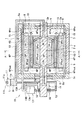
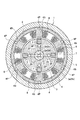
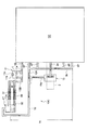
図1〜図4は本発明にかかるモータの冷却装置およびその冷却方法の第1実施形態を示し、図1はモータの断面図、図2は図1中A−A線に沿った断面図、図3は冷却装置の冷媒流通経路を示す構成図、図4は冷媒圧力の時間変動をグラフで示す説明図である。 1 to 4 show a first embodiment of a motor cooling apparatus and cooling method according to the present invention, FIG. 1 is a sectional view of the motor, FIG. 2 is a sectional view taken along line AA in FIG. FIG. 3 is a block diagram showing the refrigerant flow path of the cooling device, and FIG. 4 is an explanatory diagram showing the time variation of the refrigerant pressure in a graph.
本発明のモータは、例えばインホイールドライブ方式の電気自動車に適用され、モータをタイヤホイールの裏側に形成される中心凹部内に挿入した状態で車体側に取り付け、モータの回転軸で車輪を直接駆動するようになっている。 The motor of the present invention is applied to, for example, an in-wheel drive type electric vehicle, and is mounted on the vehicle body side in a state where the motor is inserted into a central recess formed on the back side of the tire wheel, and the wheel is directly driven by the rotation shaft of the motor. It is supposed to be.
本実施形態のモータ1は、図1,図2に示すように回転軸2と、この回転軸2に結合されたロータ3と、このロータ3の外周を囲繞するステータ4と、を備えており、これらはハウジング5内に収納される。
As shown in FIGS. 1 and 2, the motor 1 of this embodiment includes a
回転軸2はロータ3と一体となって、両端部がハウジング5の両端のエンドプレート5eに軸受6を介して回転自在に支持されるとともに、ロータ3の周縁部内方には、回転軸2の軸方向に沿って周方向に等間隔をもって複数(本実施形態では4個)のロータ磁石7が配置される。
The
ステータ4はハウジング5の内周に固定され、そのステータ4の内周には周方向に等間隔をもって複数(本実施形態では6本)のステータ凸極部4Sが突設され、それぞれのステータ凸極部4Sにはコイル8が巻回されている。
The
冷却装置10は、図1に示すようにモータ1の発熱で液相から気相に変化する冷媒Mを溜めたリザーバタンク11と、前記ロータ3および前記ステータ4のそれぞれの内部に形成されるロータ内通路3Pおよび前記ステータ内通路4Pと、これらロータ内通路3Pおよび前記ステータ内通路4Pの各入口3Pin,4Pinと前記リザーバタンク11とを連通する冷媒供給通路12と、前記ロータ内通路3Pおよび前記ステータ内通路4Pの各出口3Pout,4Poutと前記リザーバタンク11とを連通する冷媒還流通路13と、を設けるとともに、前記ロータ内通路3Pおよび前記ステータ内通路4Pの各入口3Pin,4Pin近傍に配置し、前記冷媒供給通路12方向への逆流を阻止する逆止弁14,15と、前記冷媒還流通路13に配置してこの冷媒還流通路13内の冷媒熱を外方に放熱する排熱機構としてのコンデンサ16と、を備えており、かつ、前記リザーバタンク11を、前記ロータ内通路3Pおよび前記ステータ内通路4Pよりも鉛直上方位置に配置してある。
As shown in FIG. 1, the
また、本実施形態のモータ1の冷却方法では、前記モータ1にあって、リザーバタンク11に溜めた冷媒Mを、冷媒供給通路12を介して前記ロータ3および前記ステータ4のそれぞれの内部に形成したロータ内通路3Pおよび前記ステータ内通路4Pに、それぞれの入口3Pin,4Pin近傍に設けた逆止弁14,15を介して供給した後、その冷媒Mをコンデンサ16を設けた冷媒還流通路13を介してリザーバタンク11に戻して循環させるとともに、前記リザーバタンク11を、前記ロータ内通路3Pおよび前記ステータ内通路4Pよりも鉛直上方位置に配置するようになっている。
Further, in the method for cooling the motor 1 of the present embodiment, the refrigerant M in the motor 1 is formed in each of the
このとき、冷媒還流通路13の前記コンデンサ16よりも上流側(図中上側)に、この通路13よりも断面積が大きな主チャンバ17を設けるとともに、これらコンデンサ16と主チャンバ17との間にその主チャンバ17方向への流れを阻止する逆止弁18を設けてある。
At this time, a
前記リザーバタンク11の上端面11bには大気開放口11cを形成してあり、そのリザーバタンク11の底部11aには前記冷媒供給通路12の始端部と前記冷媒還流通路13の終端部とを連通接続してあり、かつ、前記主チャンバ17よりもロータ内通路3Pの出口3Pout側に寄った位置に、そのロータ内通路3Pの排出圧を導入する副チャンバ19を設けてある。
An
前記ロータ内通路3Pは、図2に示すように4個のロータ磁石7の配置部位に対応して周方向に略等間隔に4箇所形成されるとともに、前記ステータ内通路4Pは6つのステータ凸極部4Sの突設部位に対応して周方向に略等間隔に6箇所形成される。
As shown in FIG. 2, the rotor
そして、図1に示すように前記ロータ内通路3Pをロータ3の外周部近傍に形成する一方、冷媒供給通路12からそのロータ内通路3Pに冷媒を供給する導入通路2aをロータ中心部としての回転軸2に形成し、その導入通路2aからロータ内通路3Pに至る分岐通路2bを径方向に設けてある。
As shown in FIG. 1, the
即ち、ロータ内通路3Pの冷媒導入側(図1中右側)は、図1に示すように回転軸2の一端部に形成した前記導入通路2aと、この導入通路2aからロータ3に亘って外径方向に傾斜して形成される前記分岐通路2bと、を介して前記冷媒供給通路12に連通するとともに、ロータ内通路3Pの冷媒排出側(図1中左側)は、ロータ3から回転軸2に亘って形成される分岐通路2cと、回転軸2の他端部に形成した排出通路2dと、を介して前記副チャンバ19に連通する。
That is, the refrigerant introduction side (the right side in FIG. 1) of the rotor
ステータ内通路4Pの冷媒導入側(図1中右側)は、図1に示すようにハウジング5の一端側のエンドプレート5e内部に形成した環状通路5aを介して前記冷媒供給通路12に連通するとともに、ステータ内通路4Pの冷媒排出側(図1中左側)は、ハウジング5の他端側のエンドプレート5e内部に形成した環状通路5bを介して前記冷媒還流通路13に連通する。
The refrigerant introduction side (right side in FIG. 1) of the stator
前記副チャンバ19は、通路19aを介して前記冷媒還流通路13の上流部分13Aが主チャンバ17に連通する部位に連通し、副チャンバ19に排出されたロータ内通路3Pの冷媒Mと、冷媒還流通路13に排出されたステータ内通路4Pの冷媒Mとが合流して主チャンバ17に導入される。
The
従って、前記リザーバタンク11内の冷媒Mの流れは、図3に示すように冷媒供給通路12(流れF1)から導入通路2a(流れF2)および分岐通路2b(流れF3)を介してロータ内通路3P(流れF4)に供給される一方、環状通路5a(流れF5)を介してステータ内通路4P(流れF6)に供給され、そして、ロータ内通路3P内の冷媒Mは分岐通路2c(流れF7)および排出通路2d(流れF8)を介して副チャンバ19に排出される一方、ステータ内通路4P内の冷媒Mは環状通路5b(流れF9)を介して冷媒還流通路13の上流部分13A(流れF10)に排出される。
Therefore, as shown in FIG. 3, the flow of the refrigerant M in the
そして、前記副チャンバ19および前記環状通路5aの上流部分13Aに排出された冷媒Mは前記主チャンバ17に導入(流れF11)され、この主チャンバ17に導入された冷媒Mは、前記逆止弁18を介して前記コンデンサ16を通過(流れF12)した後、冷媒還流通路13の後流部分13Bを介して前記リザーバタンク11に戻る(流れF13)ことになる。
The refrigerant M discharged to the
以上の構成により本実施形態のモータの冷却装置10およびその冷却方法によれば、鉛直上方位置に配置したリザーバタンク11から冷媒Mが重力によって冷媒供給通路12を介してロータ内通路3Pおよびステータ内通路4Pに供給され、これら通路3P,4Pを通過する間に液相の冷媒はロータ3部分の鉄損や銅損による発熱で気化し、この気化した冷媒Mでロータ3およびステータ4を効率良く冷却することができる。
With the above configuration, according to the
このとき、ロータ内通路3Pおよびステータ内通路4Pで気相となった冷媒は逆止弁14,15によって前記冷媒供給通路12側に逆流するのが防止され、そして、ロータ3およびステータ4を冷却したその気相の冷媒Mは冷媒還流通路13に流入してコンデンサ16により気相から液相に戻され、この液相の冷媒Mはそのコンデンサ16の上流側の気相の冷媒Mの圧力によりリザーバタンク11に自己循環させることができ、冷媒Mの循環経路にポンプ等の冷媒移動装置を用いる必要が無くなり、冷却装置10のコンパクト化を図ることができる。
At this time, the refrigerant in the gas phase in the rotor
また、ロータ内通路3Pおよびステータ内通路4Pで冷媒Mが気化した際の気化熱をロータ3およびステータ4の冷却に利用して冷却効率を向上できるとともに、ロータ内通路3P内およびステータ内通路4P内の冷媒量を、液相の状態で冷却する場合に比較して大幅に削減でき、冷却装置10全体の重量を減少することができる。
Further, the heat of vaporization when the refrigerant M is vaporized in the rotor
従って、モータ1のコンパクト化および軽量化を達成できることにより、インホイールドライブ方式とした場合のタイヤホイールへの組み込みを容易とし、かつ、冷却装置10の冷却効率が高まることによりモータ1の温度上昇を抑制して、高負荷状態での運転状態をより長時間維持することができる。
Therefore, the motor 1 can be made compact and light, so that it can be easily incorporated into the tire wheel in the case of the in-wheel drive system, and the cooling efficiency of the
また、本実施形態では前記作用効果に加えて、冷媒還流通路13に設けたコンデンサ16よりも上流側に主チャンバ17を設けて、これらコンデンサ16と主チャンバ17との間に逆止弁18を設けたので、主チャンバ17によってロータ内通路3Pおよびステータ内通路4Pで冷媒Mが気化される際の急激な圧力上昇を緩和して、コンデンサ16に供給する冷媒Mの圧力を安定化させることができるとともに、気化により気相状態となった冷媒Mの圧力変動によりコンデンサ16から主チャンバ17に液相の冷媒Mが逆流するのを逆止弁18で阻止できる。
In the present embodiment, in addition to the above-described effects, a
即ち、ロータ3およびステータ4が冷却されて冷媒Mが気化しない温度まで低下すると、ロータ内通路3P内およびステータ内通路4P内の圧力が低下し、次にロータ3およびステータ4の温度が上昇開始すると冷媒Mが気化するというサイクルが続く状態が存在した場合、圧力上昇のピーク値が高すぎるとコンデンサ16で冷媒Mが十分に熱交換されずに気相の状態でリザーバタンク11に戻されることになるが、前記主チャンバ17によって圧力変動を抑制することができる。
That is, when the
このとき、本実施形態では前記主チャンバ17に加えてロータ内通路3P側に副チャンバ19を設けたので、それら両チャンバ17,19によって圧力の変動抑制効率を更に高めることができる。
At this time, in this embodiment, since the
従って、前記チャンバ17,19を設けない場合と設けた場合の冷却装置10内の気体圧力Pの時間変動を図4に示すと、P1はチャンバ17,19を設けることなく冷却装置10を構成した場合、P2はチャンバ17,19を設けて冷却装置10を構成した場合で、チャンバ17,19を設けた場合は液相の冷媒Mが気化による急激な圧力上昇を緩和できることが理解される。尚、同図中P3は後述の第2実施形態で説明するものとする。
Therefore, when the time variation of the gas pressure P in the
更に、ロータ内通路3Pをロータ3の外周部近傍に形成する一方、冷媒供給通路12からそのロータ内通路3Pに冷媒を供給する導入通路2aを回転軸2に形成し、その導入通路2aからロータ内通路3Pに至る分岐通路2bを径方向に設けたので、その径方向の分岐通路2bに存在する液相の冷媒Mにロータ3回転時の遠心力が作用するため、この遠心力によるポンプ作用で冷媒供給通路12内の冷媒Mをロータ内通路3Pに供給することができるので、このロータ内通路3Pの径を、重力のみで冷媒Mを供給する前記ステータ内通路4Pよりも小さくすることができ、その分、ロータ3内の冷媒M量を減少させることができ、ひいては、冷媒Mの重量によるロータ3の回転抵抗を減少することができる。
Further, the rotor
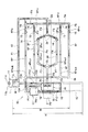
図5は本発明の第2実施形態を示し、前記第1実施形態と同一構成部分に同一符号を付して重複する説明を省略して述べるものとし、図5は冷却装置の冷媒流通経路を示す構成図である。 FIG. 5 shows a second embodiment of the present invention, in which the same components as those in the first embodiment are denoted by the same reference numerals and redundant description is omitted, and FIG. 5 shows the refrigerant flow path of the cooling device. FIG.
本実施形態の冷却装置10Aは、図5に示すように基本的に第1実施形態と略同様の構成となり、冷媒Mを溜めたリザーバタンク11と、ロータ内通路3Pおよび前記ステータ内通路4Pと、冷媒供給通路12と、冷媒還流通路13と、各入口3Pin,4Pin近傍に配置した逆止弁14,15と、冷媒還流通路13に配置したコンデンサ16と、を設けてあり、かつ、前記リザーバタンク11をロータ内通路3Pおよびステータ内通路4Pよりも鉛直上方位置に配置してある。
As shown in FIG. 5, the
また、冷媒還流通路13の前記コンデンサ16よりも上流側に逆止弁18を有する主チャンバ17を設けるとともに、ロータ内通路3Pの排出圧を導入する副チャンバ19を設けてある。
A
そして、本実施形態では前記主チャンバ17に、その内部圧力の変動を吸収するアキュムレータ20を設けてある。
In this embodiment, the
また、前記アキュムレータ20を設けるにあたって、主チャンバ17とそのアキュムレータ20とを2つの連通路21,22を介して連通し、それら複数の連通路21,22のうちのいずれか一方に、アキュムレータ20から主チャンバ17方向への流れを阻止する逆止弁23を設けてある。
Further, when the
前記アキュムレータ20は、図5に示すように密閉容器20a内を上下に摺動自在に隔成するピストン20bと、このピストン20bを下方に押圧するスプリング20cと、を備え、ピストン20bで隔成した下方室を圧力調整室20dとし、この圧力調整室20dと主チャンバ17の上部とを前記連通路21,22で連通してある。
As shown in FIG. 5, the
前記連通路21,22のうち一方の連通路21は、第1実施形態に示した冷媒還流通路13の上流部分13Aの一部であり、他方の連通路22を本実施形態で新たに設けて、この連通路22に前記逆止弁23を設けてある。
One
そして、ロータ内通路3Pおよびステータ内通路4Pで冷媒Mの気化が促進して、気相の冷媒Mの圧力が上昇することに伴って主チャンバ17内の気体圧力が高まると、この主チャンバ17内の圧力は連通路21,22を介してアキュムレータ20の圧力調整室20dに導入されて、この圧力調整室20dの室内容積を拡大する。
When the gas pressure in the
一方、ロータ内通路3Pおよびステータ内通路4Pの冷媒Mの気化が鈍化して主チャンバ17内の圧力が低下すると、アキュムレータ20のピストン20bがスプリング20cの付勢力で下降して圧力調整室20dの室内容積を縮小し、この圧力調整室20d内の圧力が連通路21を介して主チャンバ17内に導入される。
On the other hand, when the vaporization of the refrigerant M in the rotor
従って、本実施形態によれば、主チャンバ17内の圧力が高まると、アキュムレータ20の圧力調整室20dの容積拡大によって主チャンバ17内の急激な圧力上昇を抑制できる一方、主チャンバ17内の圧力が低下すると、アキュムレータ20の圧力調整室20dの容積縮小によって、主チャンバ17の急激な圧力低下を抑制することができる。
Therefore, according to the present embodiment, when the pressure in the
特に、本実施形態では主チャンバ17とアキュムレータ20とを2つの連通路21,22を介して連通し、一方の連通路22に逆止弁23を設けてあるので、主チャンバ17からアキュムレータ20に圧力が導入される際には、2つの連通路21,22を介して気相の冷媒Mがアキュムレータ20に導入されるため、迅速に主チャンバ17内の圧力上昇を抑制できるとともに、アキュムレータ20から主チャンバ17に圧力が戻される際には、1つの連通路21のみを介して気相の冷媒Mが主チャンバ17に導入されるため、この主チャンバ17の急激な圧力上昇を抑制することができる。
In particular, in this embodiment, the
従って、本実施形態による冷却装置10内の気体圧力Pの時間変動は、図4のP3に示すように緩やかな変動となり、コンデンサ16での冷媒Mの液化を安定的に、かつ効率良く行うことができる。
Therefore, the time variation of the gas pressure P in the
このように本実施形態では格別なポンプなしにチャンバ23やロータ、ステータ通路までは冷媒液が逆流しない構造となっている。そして、再び冷媒液が通路内に供給されて、再び蒸発が起こるというサイクルが続く状態が存在するが、本出願人の試算によれば、出力20kWのモータの10%がモータ内の熱損失とすれば、2kWの熱損があることになる。このとき冷媒を水、モータ周りの圧力を大気圧、リザーバタンク内の液面と流路のうち鉛直下向き最下部に位置する流路の高さHを1mとすれば冷媒による最大位置水頭ρgHはコンデンサ出口水温を50℃とすれば、ρgH=988×9.8×1=9682N/m2となり大気圧(101.3kN/m2)の1割弱であり、流通抵抗を無視できる静的な場合、ロータ、ステータ通路内の圧力が少なくとも大気圧+ρgH=111kN/m2以上になれば冷媒液はリザーバタンクへ戻ることができる。水の飽和圧力が111kN/m2のときに対する飽和温度は約102.3℃であり、本発明を実現する構成の強度は十分達成可能である。一方、2kWの発熱で飽和水を全部蒸気にするためには、飽和温度102.3℃に対する蒸発潜熱は2251kJ/kgであるので、2(kW)/2251(kJ/kg)/998(kg/m3)=8.99×10-7(m3/s)=540×10-2(1/min)となり、ごく少量の毎分54ccの冷却水を供給すれば流路周りの最高温度は百数度に保たれることになり、位置水頭による圧力でも十分に冷却水を供給できる範囲である。
Thus, in the present embodiment, the refrigerant liquid does not flow back to the
図6,図7は本発明の第3実施形態を示し、第1実施形態と同一構成部分に同一符号を付して重複する説明を省略して述べるものとし、図6は冷却装置の冷媒流通経路を示す要部構成図、図7は冷却装置の冷媒流通経路の作動状態を示す要部構成図である。 6 and 7 show a third embodiment of the present invention, in which the same components as in the first embodiment are denoted by the same reference numerals and redundant description is omitted, and FIG. 6 is a refrigerant flow of the cooling device. The principal part block diagram which shows a path | route, FIG. 7: is a principal part block diagram which shows the operating state of the refrigerant | coolant flow path of a cooling device.
本実施形態の冷却装置10Bは、図6,図7に示すように基本的に第1実施形態と略同様に冷媒Mを溜めたリザーバタンク11と、主チャンバ17と、副チャンバ19と、を備えており、また、同図中のブラックボックスB1は第1実施形態と同様となり、冷媒供給通路12やロータ内通路3Pおよびステータ内通路4Pが設けられる。
As shown in FIGS. 6 and 7, the
そして、本実施形態では、前記主チャンバ17への連通位置が鉛直下方位置となる下方排熱機構としての下方コンデンサ30と、同連通位置が鉛直上方位置となる上方排熱機構としての上方コンデンサ31とを設け、下方コンデンサ30の冷媒流通抵抗を上方コンデンサ31よりも大きくするとともに、下方コンデンサ30と主チャンバ17との間に、この主チャンバ17方向への流れを阻止する逆止弁32を設けてある。
And in this embodiment, the lower capacitor |
このとき、下方コンデンサ30は第1実施形態のコンデンサ16と同様に主チャンバ17の底面に連通する一方、前記上方コンデンサ31は主チャンバ17の側面に形成した開口部17aを介してその主チャンバ17に連通する。
At this time, the
尚、本実施形態の下方コンデンサ30および逆止弁32は、第1,第2実施形態に示すコンデンサ16および逆止弁18と同様の構成として捉えることができ、かつ、前記上方コンデンサ31の冷媒排出側は、前記下方コンデンサ30の冷媒排出側と同様に冷媒還流通路13の後流部分13Bに接続してある。
The
また、前記上方コンデンサ31の流路径を下方コンデンサ30よりも小さくし、若しくはその流路に絞り弁等の抵抗体を設けることなどにより、その上方コンデンサ31の冷媒Mの流通抵抗を下方コンデンサ30よりも大きくしてある。
Further, the flow resistance of the refrigerant M in the
図6は、主チャンバ17内に気相の冷媒Mgと液相の冷媒Mlとが混在し、液相の冷媒Mlの液面が上方コンデンサ31の開口部17aよりも上方に位置した場合を示し、主チャンバ17内の液相の冷媒Mlは、下方コンデンサ30と上方コンデンサ31の両方を流通した後、冷媒還流通路13の下流部分13Bからリザーバタンク11に戻るようになっている。
FIG. 6 shows a case where the gas phase refrigerant Mg and the liquid phase refrigerant Ml are mixed in the
図7は、主チャンバ17内の圧力が高くなって、液相の冷媒Mlの液面が上方コンデンサ31の開口部17aよりも下方に位置した場合を示し、気相の冷媒Mgは上方コンデンサ31に流入するようになっている。
FIG. 7 shows the case where the pressure in the
従って、本実施形態によれば、主チャンバ17内の圧力が高くなると、図7に示すように流通抵抗の違いにより冷媒Mgの圧力が上方コンデンサ31に流入し、そして、この状態から主チャンバ17内の圧力が低下するときには、上方コンデンサ31内の気相の冷媒Mgが開口部17aから主チャンバ17内に流入する。
Therefore, according to this embodiment, when the pressure in the
このため、上方コンデンサ31内の冷媒Mの流れ(F14)は、主チャンバ17内の圧力に応じて流れの方向が異なり、主チャンバ17の急激な圧力上昇および低下を抑制することができ、ひいては、冷却装置10内の気体圧力Pの時間変動が、第2実施形態と同様に図4のP3に示すように緩やかな変動となり、コンデンサ16での冷媒Mの液化を安定的に、かつ効率良く行うことができる。
For this reason, the flow (F14) of the refrigerant M in the
特に、図7の状態から図6の状態に戻るときには、上方コンデンサ31を一度通過して温度が低下した冷媒Mが再度その上方コンデンサ31で熱交換されるため、リザーバタンク11に戻される冷媒Mの温度をより下げることができる。
In particular, when returning from the state of FIG. 7 to the state of FIG. 6, the refrigerant M that has once passed through the
図8は本発明の第4実施形態を示し、前記第3実施形態と同一構成部分に同一符号を付して重複する説明を省略して述べるものとし、図8は冷却装置の冷媒流通経路を示す要部構成図である。 FIG. 8 shows a fourth embodiment of the present invention, in which the same components as those in the third embodiment are denoted by the same reference numerals and redundant description is omitted, and FIG. 8 shows the refrigerant flow path of the cooling device. It is a principal part block diagram shown.
本実施形態の冷却装置10Cは、図8に示すように基本的に第3実施形態と同様の構成となり、主チャンバ17への連通位置が鉛直下方位置となる下方コンデンサ30と、同連通位置が鉛直上方位置となる上方コンデンサ31とを設け、下方コンデンサ30と主チャンバ17との間に、この主チャンバ17方向への流れを阻止する逆止弁32を設けてある。
As shown in FIG. 8, the cooling device 10C of the present embodiment basically has the same configuration as that of the third embodiment, and includes a
また、第1実施形態と略同様に冷媒Mを溜めたリザーバタンク11と、主チャンバ17と、副チャンバ19と、を備えており、また、同図中のブラックボックスB2は第1実施形態と同様となり、冷媒供給通路12やロータ内通路3Pおよびステータ内通路4Pが設けられる。
Moreover, it has the
そして、本実施形態では排熱機構としての前記下方コンデンサ30と前記上方コンデンサ31を、リザーバタンク11の冷媒液面Lよりも鉛直方向で上方位置に配置してある。
In the present embodiment, the
従って、本実施形態によれば、前記第3実施形態と同様の作用効果を奏するのは勿論のこと、特に、下方コンデンサ30と上方コンデンサ31をリザーバタンク11の冷媒液面Lよりも鉛直方向で上方位置に配置したので、ロータ内通路3Pおよびステータ内通路4Pを通過して主チャンバ17内に流入する冷媒Mが気相の場合、下方コンデンサ30および上方コンデンサ31内の液相化した冷媒Mをリザーバタンク11に戻す圧力が不要になり、ロータ内通路3Pおよびステータ内通路4Pで気相化される冷媒Mがより小さい圧力で冷媒Mの循環が可能となる。
Therefore, according to the present embodiment, the same effect as that of the third embodiment can be obtained. In particular, the
勿論、本実施形態は第1,第2実施形態の単一のコンデンサ16を設けた場合にも適用することができる。
Of course, this embodiment can also be applied to the case where the
図9は本発明の第5実施形態を示し、前記第1実施形態と同一構成部分に同一符号を付して重複する説明を省略して述べるものとし、図9は冷却装置の冷媒流通経路を示す要部構成図である。 FIG. 9 shows a fifth embodiment of the present invention, in which the same components as those in the first embodiment are denoted by the same reference numerals and redundant description is omitted, and FIG. 9 shows the refrigerant flow path of the cooling device. It is a principal part block diagram shown.
本実施形態の冷却装置10Dは、図9に示すように基本的に第1実施形態と略同様の構成となり、冷媒Mを溜めたリザーバタンク11と、コンデンサ16と、主チャンバ17と、副チャンバ19と、を備えており、また、同図中のブラックボックスB3は第1実施形態と同様となり、冷媒供給通路12やロータ内通路3Pおよびステータ内通路4Pが設けられる。
As shown in FIG. 9, the
そして、本実施形態では前記コンデンサ16をリザーバタンク11の上端面11bよりも鉛直上方位置に配置して、そのコンデンサ16をリザーバタンク11の上端面11bに連通してある。
In the present embodiment, the
従って、本実施形態によれば、コンデンサ16を設けた前記第1,2実施形態と同様の作用効果を奏するのは勿論のこと、特に、そのコンデンサ16をリザーバタンク11の上端面11bよりも鉛直上方位置に配置して、そのコンデンサ16をリザーバタンク11の上端面11bに連通したので、ロータ内通路3Pおよびステータ内通路4Pを通過して主チャンバ17内に流入する冷媒Mが気相の場合、コンデンサ16内の液相化した冷媒Mをリザーバタンク11に戻す圧力が不要になり、ロータ内通路3Pおよびステータ内通路4Pで気相化される冷媒Mがより小さい圧力で冷媒Mの循環が可能となる。
Therefore, according to the present embodiment, the same effect as in the first and second embodiments provided with the
また、コンデンサ16をリザーバタンク11の上端面11bよりも鉛直上方位置に配置したので、リザーバタンク11内の冷媒液面Lに対する水頭分の圧力がコンデンサ16に作用しないため、第4実施形態に比べてより小さい圧力で冷媒Mの循環が可能となる。
In addition, since the
勿論、本実施形態は第1,第2実施形態の単一のコンデンサ16を設けた場合、および第3実施形態の2つのコンデンサ30,31を設けた場合にも適用することができる。
Of course, this embodiment can also be applied to the case where the
ところで、前記第1〜第5実施形態において、冷却装置10〜10Dに使用される冷媒Mは、主チャンバ17内圧力をp、冷媒Mの液体密度ρ、重力加速度g、リザーバタンク11内の冷媒液面Lと鉛直最下方位置のステータ内通路4Pとの高さをH(図3,図5〜図8参照)とした場合に、p>ρ・g・H…(1)の式を満足する物性値を備えたものを用いてある。
By the way, in the first to fifth embodiments, the refrigerant M used in the
尚、図3および図5〜図7中破線に示すように、冷媒還流通路13の鉛直最下方位置が前記ステータ内通路4Pよりも下方となる場合、前記Hはその破線で示す冷媒還流通路13の鉛直最下方位置とリザーバタンク11の冷媒液面Lとの高さとなる。
3 and 5 to 7, when the vertically lowermost position of the
従って、冷媒Mの物性値が前記(1)の式を満足することにより、冷媒Mが冷却装置10のいずれかの流路内に液相で存在する場合にあっても、冷媒Mをポンプ無しにリザーバタンク11に戻すことができる。
Therefore, when the physical property value of the refrigerant M satisfies the expression (1), the refrigerant M is not pumped even when the refrigerant M exists in a liquid phase in any flow path of the
また、第1〜第5実施形態ではコンデンサ16およびコンデンサ30,31は概略的に1つの直管を配置した状態で示すが、勿論、通常の熱交換器のように複数の直管に冷媒を通過させても良く、また、冷媒の通過管を蛇行させても良いことはいうまでない。
In the first to fifth embodiments, the
更に、図2に示すようにロータ内通路3Pを4本、ステータ内通路4Pを6本設けた場合を示すが、これらロータ内通路3Pおよびステータ内通路4Pの形成本数はこれに限ること無く、モータ1を効果的に冷却できる本数に設定することができる。
Furthermore, as shown in FIG. 2, the case where four
勿論、本発明のモータの冷却装置は前記第1〜第5実施形態に例をとって説明したが、これら実施形態に限ることなく本発明の要旨を逸脱しない範囲で他の実施形態を各種採用することができ、例えば、モータ1はインホイールドライブ方式の電気自動車に限ることなく、通常のモータにあっても本発明を適用することができる。 Of course, the motor cooling device of the present invention has been described by taking the first to fifth embodiments as an example. However, the present invention is not limited to these embodiments, and various other embodiments are adopted without departing from the scope of the present invention. For example, the motor 1 is not limited to an in-wheel drive type electric vehicle, and the present invention can also be applied to a normal motor.
1 モータ
2 回転軸
2a 導入通路
2b 分岐通路
3 ロータ
3P ロータ内通路
3Pin ロータ内通路の入口
3Pout ロータ内通路の出口
4 ステータ
4P ステータ内通路
4Pin ステータ内通路の入口
4Pout ステータ内通路の出口
10,10A,10B,10C,10D 冷却装置
11 リザーバタンク
11b リザーバタンクの上端面
12 冷媒供給通路
13 冷媒還流通路
14,15 逆止弁
16 コンデンサ(排熱機構)
17 主チャンバ
18 逆止弁
20 アキュムレータ
21,22 連通路
23 逆止弁
30 下方コンデンサ(下方排熱機構)
31 上方コンデンサ(上方排熱機構)
32 逆止弁
M 冷媒
L 冷媒液面
DESCRIPTION OF SYMBOLS 1
17
31 Upper condenser (Upper heat exhaust mechanism)
32 Check valve M Refrigerant L Refrigerant liquid level
Claims (9)
モータの発熱で液相から気相に変化する冷媒を溜めたリザーバタンクと、
前記ロータおよび前記ステータのそれぞれの内部に形成されるロータ内通路およびステータ内通路と、
前記ロータ内通路および前記ステータ内通路の各入口と前記リザーバタンクとを連通する冷媒供給通路と、
前記ロータ内通路および前記ステータ内通路の各出口と前記リザーバタンクとを連通する冷媒還流通路と、
前記ロータ内通路および前記ステータ内通路の各入口近傍に配置し、前記冷媒供給通路方向への逆流を阻止する逆止弁と、
前記冷媒還流通路に配置してこの冷媒還流通路内の冷媒熱を外方に放熱する排熱機構と、を設け、
前記リザーバタンクを前記ロータ内通路および前記ステータ内通路よりも鉛直上方位置に配置したことを特徴とするモータの冷却装置。 In a motor comprising a rotating shaft, a rotor coupled to the rotating shaft, and a stator surrounding the outer periphery of the rotor,
A reservoir tank that stores a refrigerant that changes from a liquid phase to a gas phase by the heat generated by the motor;
A rotor internal passage and a stator internal passage formed in each of the rotor and the stator, and
A refrigerant supply passage communicating the inlets of the rotor passage and the stator passage with the reservoir tank;
A refrigerant recirculation passage that communicates each outlet of the rotor passage and the stator passage with the reservoir tank;
A check valve that is disposed in the vicinity of each inlet of the rotor inner passage and the stator inner passage and prevents a reverse flow in the direction of the refrigerant supply passage;
An exhaust heat mechanism disposed in the refrigerant recirculation passage to dissipate heat of the refrigerant in the refrigerant recirculation passage outward;
The motor cooling apparatus according to claim 1, wherein the reservoir tank is arranged at a position vertically above the rotor inner passage and the stator inner passage.
リザーバタンクに溜めた冷媒を、冷媒供給通路を介して前記ロータおよび前記ステータのそれぞれの内部に形成したロータ内通路および前記ステータ内通路に、それぞれの入口近傍に設けた逆止弁を介して供給した後、その冷媒を排熱機構を設けた冷媒還流通路を介してリザーバタンクに戻して循環させるとともに、前記リザーバタンクを前記ロータ内通路および前記ステータ内通路よりも鉛直上方位置に配置したことを特徴とするモータの冷却方法。 In a motor comprising a rotating shaft, a rotor coupled to the rotating shaft, and a stator surrounding the outer periphery of the rotor,
The refrigerant stored in the reservoir tank is supplied to the rotor inner passage formed in the rotor and the stator and the stator inner passage through the refrigerant supply passage through check valves provided in the vicinity of the respective inlets. After that, the refrigerant is circulated back to the reservoir tank through the refrigerant recirculation passage provided with the exhaust heat mechanism, and the reservoir tank is disposed vertically above the rotor inner passage and the stator inner passage. A motor cooling method as a feature.
Priority Applications (2)
| Application Number | Priority Date | Filing Date | Title |
|---|---|---|---|
| JP2004346024A JP4654672B2 (en) | 2004-11-30 | 2004-11-30 | Motor cooling device and cooling method thereof. |
| US11/287,689 US7462963B2 (en) | 2004-11-30 | 2005-11-28 | Motor cooling device and cooling method |
Applications Claiming Priority (1)
| Application Number | Priority Date | Filing Date | Title |
|---|---|---|---|
| JP2004346024A JP4654672B2 (en) | 2004-11-30 | 2004-11-30 | Motor cooling device and cooling method thereof. |
Publications (2)
| Publication Number | Publication Date |
|---|---|
| JP2006158105A true JP2006158105A (en) | 2006-06-15 |
| JP4654672B2 JP4654672B2 (en) | 2011-03-23 |
Family
ID=36635712
Family Applications (1)
| Application Number | Title | Priority Date | Filing Date |
|---|---|---|---|
| JP2004346024A Expired - Fee Related JP4654672B2 (en) | 2004-11-30 | 2004-11-30 | Motor cooling device and cooling method thereof. |
Country Status (1)
| Country | Link |
|---|---|
| JP (1) | JP4654672B2 (en) |
Cited By (11)
| Publication number | Priority date | Publication date | Assignee | Title |
|---|---|---|---|---|
| JP2010502163A (en) * | 2006-08-22 | 2010-01-21 | シーメンス アクチエンゲゼルシヤフト | Self-cooling electric motor |
| JP2010252502A (en) * | 2009-04-15 | 2010-11-04 | Nissan Motor Co Ltd | Rotary electric machine |
| CN102510172A (en) * | 2011-11-21 | 2012-06-20 | 哈尔滨电机厂有限责任公司 | Secondary cooling system for hydraulic generator |
| DE112009002428T5 (en) | 2008-10-27 | 2012-09-13 | Toyota Jidosha K.K. | Rotating electrical machine |
| JP2013526826A (en) * | 2010-05-19 | 2013-06-24 | シーレイト リミテッド ライアビリティー カンパニー | Heat removal from motor |
| JP2014502488A (en) * | 2010-11-04 | 2014-01-30 | ヴォッベン プロパティーズ ゲーエムベーハー | Wind power generator having a synchronous generator and a slowly rotating synchronous generator |
| US9397591B2 (en) | 2010-05-19 | 2016-07-19 | Deep Science Llc | Motor with rotor-mounted control circuitry |
| JP2019500843A (en) * | 2015-12-18 | 2019-01-10 | ビューラー モーター ゲゼルシャフト ミット ベシュレンクテル ハフツング | Brushless electric motor for pump, pump having this kind of electric motor and cooling method |
| KR20190051073A (en) | 2016-11-24 | 2019-05-14 | 가부시키가이샤 앰링크 | A non-iron-core rotary electric machine for operating in a load exceeding a rated value, a drive method thereof, and a drive system including the same |
| KR20210065676A (en) | 2019-11-27 | 2021-06-04 | 엘지전자 주식회사 | Rotating electric machine |
| JP2021097580A (en) * | 2019-12-13 | 2021-06-24 | 饒梦華 | Motor that can dissipate heat efficiently |
Citations (7)
| Publication number | Priority date | Publication date | Assignee | Title |
|---|---|---|---|---|
| JPS62113817A (en) * | 1985-11-12 | 1987-05-25 | Nissan Motor Co Ltd | Evaporative cooling device for engine |
| JPS62294714A (en) * | 1986-06-12 | 1987-12-22 | Nissan Motor Co Ltd | Evaporative cooling apparatus for internal combustion engine |
| JPH0420788A (en) * | 1990-05-16 | 1992-01-24 | Toshiba Corp | Cooling device and temperature control device |
| JPH0923614A (en) * | 1995-07-10 | 1997-01-21 | Mitsubishi Alum Co Ltd | Cooler for motor in electric vehicle |
| JPH0974715A (en) * | 1995-09-01 | 1997-03-18 | Denso Corp | Unitary-body type heater with ebullient cooler |
| JPH10336968A (en) * | 1997-05-29 | 1998-12-18 | Denso Corp | Rotating electric machine for vehicle |
| JP2003102147A (en) * | 2001-09-26 | 2003-04-04 | Nissan Motor Co Ltd | Cooling device for motor |
-
2004
- 2004-11-30 JP JP2004346024A patent/JP4654672B2/en not_active Expired - Fee Related
Patent Citations (7)
| Publication number | Priority date | Publication date | Assignee | Title |
|---|---|---|---|---|
| JPS62113817A (en) * | 1985-11-12 | 1987-05-25 | Nissan Motor Co Ltd | Evaporative cooling device for engine |
| JPS62294714A (en) * | 1986-06-12 | 1987-12-22 | Nissan Motor Co Ltd | Evaporative cooling apparatus for internal combustion engine |
| JPH0420788A (en) * | 1990-05-16 | 1992-01-24 | Toshiba Corp | Cooling device and temperature control device |
| JPH0923614A (en) * | 1995-07-10 | 1997-01-21 | Mitsubishi Alum Co Ltd | Cooler for motor in electric vehicle |
| JPH0974715A (en) * | 1995-09-01 | 1997-03-18 | Denso Corp | Unitary-body type heater with ebullient cooler |
| JPH10336968A (en) * | 1997-05-29 | 1998-12-18 | Denso Corp | Rotating electric machine for vehicle |
| JP2003102147A (en) * | 2001-09-26 | 2003-04-04 | Nissan Motor Co Ltd | Cooling device for motor |
Cited By (21)
| Publication number | Priority date | Publication date | Assignee | Title |
|---|---|---|---|---|
| JP2010502163A (en) * | 2006-08-22 | 2010-01-21 | シーメンス アクチエンゲゼルシヤフト | Self-cooling electric motor |
| DE112009002428B4 (en) * | 2008-10-27 | 2021-01-21 | Toyota Jidosha Kabushiki Kaisha | Rotating electric machine |
| DE112009002428T5 (en) | 2008-10-27 | 2012-09-13 | Toyota Jidosha K.K. | Rotating electrical machine |
| US8492941B2 (en) | 2008-10-27 | 2013-07-23 | Toyota Jidosha Kabushiki Kaisha | Rotating electric machine with improved rotor shaft coolant channel structure |
| DE112009002428B8 (en) * | 2008-10-27 | 2021-05-20 | Toyota Jidosha Kabushiki Kaisha | Rotating electric machine |
| JP2010252502A (en) * | 2009-04-15 | 2010-11-04 | Nissan Motor Co Ltd | Rotary electric machine |
| JP2013526826A (en) * | 2010-05-19 | 2013-06-24 | シーレイト リミテッド ライアビリティー カンパニー | Heat removal from motor |
| US9397591B2 (en) | 2010-05-19 | 2016-07-19 | Deep Science Llc | Motor with rotor-mounted control circuitry |
| US9722468B2 (en) | 2010-05-19 | 2017-08-01 | Deep Science Llc | Motor with rotor-mounted control circuitry |
| JP2014502488A (en) * | 2010-11-04 | 2014-01-30 | ヴォッベン プロパティーズ ゲーエムベーハー | Wind power generator having a synchronous generator and a slowly rotating synchronous generator |
| JP2015228794A (en) * | 2010-11-04 | 2015-12-17 | ヴォッベン プロパティーズ ゲーエムベーハーWobben Properties Gmbh | Wind power generator having synchronous generator and synchronous generator rotating slowly |
| US9377008B2 (en) | 2010-11-04 | 2016-06-28 | Wobben Properties Gmbh | Wind energy installation having a synchronous generator, and slowly rotating synchronous generator |
| CN102510172A (en) * | 2011-11-21 | 2012-06-20 | 哈尔滨电机厂有限责任公司 | Secondary cooling system for hydraulic generator |
| JP2019500843A (en) * | 2015-12-18 | 2019-01-10 | ビューラー モーター ゲゼルシャフト ミット ベシュレンクテル ハフツング | Brushless electric motor for pump, pump having this kind of electric motor and cooling method |
| KR20200049914A (en) | 2016-11-24 | 2020-05-08 | 가부시키가이샤 앰링크 | Coreless Rotating Electric Machine |
| DE112016007469T5 (en) | 2016-11-24 | 2019-08-14 | M-Link Co., Ltd. | Coreless rotating electrical machine for operation with overload, drive method for this and this containing drive system |
| KR20190051073A (en) | 2016-11-24 | 2019-05-14 | 가부시키가이샤 앰링크 | A non-iron-core rotary electric machine for operating in a load exceeding a rated value, a drive method thereof, and a drive system including the same |
| US11251683B2 (en) | 2016-11-24 | 2022-02-15 | M-Link Co., Ltd. | Coreless rotating electrical machine for being operated under load exceeding rating, driving method thereof, and driving system including thereof |
| US11563361B2 (en) | 2016-11-24 | 2023-01-24 | M-Link Co., Ltd. | Coreless rotating electrical machine for being operated under load exceeding rating, driving method thereof, and driving system including thereof |
| KR20210065676A (en) | 2019-11-27 | 2021-06-04 | 엘지전자 주식회사 | Rotating electric machine |
| JP2021097580A (en) * | 2019-12-13 | 2021-06-24 | 饒梦華 | Motor that can dissipate heat efficiently |
Also Published As
| Publication number | Publication date |
|---|---|
| JP4654672B2 (en) | 2011-03-23 |
Similar Documents
| Publication | Publication Date | Title |
|---|---|---|
| US7462963B2 (en) | Motor cooling device and cooling method | |
| US20070199339A1 (en) | Apparatus for cooling a heat-generating member and method | |
| JP4654672B2 (en) | Motor cooling device and cooling method thereof. | |
| JP2017203407A (en) | Turbocharger | |
| US9065313B2 (en) | Centrifugal heat dissipation device and motor using same | |
| JP5940778B2 (en) | Cooling system | |
| JP6575690B2 (en) | Equipment temperature controller | |
| JP4816884B2 (en) | Motor cooling device and cooling method. | |
| JP6593544B2 (en) | Equipment temperature controller | |
| WO2018047534A1 (en) | Instrument temperature adjustment device | |
| KR102018231B1 (en) | Electric motor | |
| JP2014029232A (en) | Cooling device | |
| JP2015165575A (en) | Heat exchange type cooling apparatus for transformer | |
| JP2010148272A (en) | Inverter and device for cooling motor | |
| JP2009038864A (en) | Cooler for motor and cooling method thereof | |
| JP4208620B2 (en) | Refrigerant cycle equipment | |
| JP2006046699A (en) | Air refrigerant type cooler and air refrigerant cold heat system using the air refrigerant type cooler | |
| JP2011190777A (en) | Single screw compressor, and refrigeration cycle device loaded with the same | |
| JPH10336968A (en) | Rotating electric machine for vehicle | |
| JP2012244659A (en) | Stator structure of rotary electric machine | |
| CN109742903B (en) | Vehicle, hub motor heat dissipation system thereof and hub motor heat dissipation method | |
| BR112019015739A2 (en) | ROTATING ELECTRICAL MACHINE, AND, METHOD FOR COOLING A ROTATING ELECTRICAL MACHINE | |
| JP2006197767A (en) | Cooling device for motor and cooling method therefor | |
| JP4115296B2 (en) | Transcritical refrigerant cycle equipment | |
| JPH0923614A (en) | Cooler for motor in electric vehicle |
Legal Events
| Date | Code | Title | Description |
|---|---|---|---|
| A621 | Written request for application examination |
Free format text: JAPANESE INTERMEDIATE CODE: A621 Effective date: 20071029 |
|
| A977 | Report on retrieval |
Free format text: JAPANESE INTERMEDIATE CODE: A971007 Effective date: 20100519 |
|
| A131 | Notification of reasons for refusal |
Free format text: JAPANESE INTERMEDIATE CODE: A131 Effective date: 20100525 |
|
| A521 | Written amendment |
Free format text: JAPANESE INTERMEDIATE CODE: A523 Effective date: 20100721 |
|
| A131 | Notification of reasons for refusal |
Free format text: JAPANESE INTERMEDIATE CODE: A131 Effective date: 20100824 |
|
| A521 | Written amendment |
Free format text: JAPANESE INTERMEDIATE CODE: A523 Effective date: 20101021 |
|
| TRDD | Decision of grant or rejection written | ||
| A01 | Written decision to grant a patent or to grant a registration (utility model) |
Free format text: JAPANESE INTERMEDIATE CODE: A01 Effective date: 20101124 |
|
| A01 | Written decision to grant a patent or to grant a registration (utility model) |
Free format text: JAPANESE INTERMEDIATE CODE: A01 |
|
| A61 | First payment of annual fees (during grant procedure) |
Free format text: JAPANESE INTERMEDIATE CODE: A61 Effective date: 20101207 |
|
| FPAY | Renewal fee payment (event date is renewal date of database) |
Free format text: PAYMENT UNTIL: 20140107 Year of fee payment: 3 |
|
| R150 | Certificate of patent or registration of utility model |
Free format text: JAPANESE INTERMEDIATE CODE: R150 |
|
| LAPS | Cancellation because of no payment of annual fees |