JP2006148612A - Acoustic device - Google Patents
Acoustic device Download PDFInfo
- Publication number
- JP2006148612A JP2006148612A JP2004336843A JP2004336843A JP2006148612A JP 2006148612 A JP2006148612 A JP 2006148612A JP 2004336843 A JP2004336843 A JP 2004336843A JP 2004336843 A JP2004336843 A JP 2004336843A JP 2006148612 A JP2006148612 A JP 2006148612A
- Authority
- JP
- Japan
- Prior art keywords
- layer
- water
- acoustic device
- water repellent
- vibration film
- Prior art date
- Legal status (The legal status is an assumption and is not a legal conclusion. Google has not performed a legal analysis and makes no representation as to the accuracy of the status listed.)
- Pending
Links
Images


Abstract
Description
本発明は、音響装置に係り、更に詳しくは、耐湿性能を改善することができる音響装置に関する。 The present invention relates to an acoustic device, and more particularly to an acoustic device capable of improving moisture resistance.
従来より、静電スピーカ等の音響装置が知られており、この音響装置は、シート状をなす振動膜と、この振動膜の両面側に配置された導電性を有する一対の固定極層と、各固定極層の外側にそれぞれ積層されて当該固定極層の定形性を維持する多孔質層とを備えて構成されている。固定極層及び多孔質層は、不織布等の空気を通す素材により構成され、振動膜の振動による再生音を透過するようになっている(特許文献1参照)。
しかしながら、このような音響装置にあっては、湿度が比較的高い場所に放置すると、静電容量が小さくなって再生音圧が低下するという不都合がある。
これは、水分を含むことにより不織布の繊維結合が破壊され、固定極層に電気が導通し難くなって電極有効面積が減ったり、固定極層が水分に触れて酸化し、電極としての機能が不十分になったりするためと推測される。
これにより、湿度を比較的低く保つように管理する等、取り扱いに多大な負担を強いられたり、湿度管理を行えない場所では音圧低下を回避できなくなるという不都合を招来する。
However, in such an acoustic device, if left in a place where the humidity is relatively high, there is an inconvenience that the capacitance decreases and the reproduced sound pressure decreases.
This is because the fiber bond of the nonwoven fabric is broken by containing moisture, and it becomes difficult to conduct electricity to the fixed electrode layer, the effective area of the electrode is reduced, or the fixed electrode layer is oxidized by contact with water, and the function as an electrode is achieved. It is presumed to be insufficient.
This causes inconveniences such as managing the humidity so as to be kept relatively low, and imposes a heavy burden on handling, and makes it impossible to avoid a decrease in sound pressure in a place where humidity management cannot be performed.
[発明の目的]
本発明は、このような不都合に着目して案出されたものであり、その目的は、耐湿性能を改善して取扱性を向上させることができる音響装置を提供することにある。
[Object of invention]
The present invention has been devised by paying attention to such inconveniences, and an object of the present invention is to provide an acoustic device capable of improving moisture resistance and improving handling.
前記目的を達成するため、本発明は、振動膜と、当該振動膜との間に空隙部を含むように積層された導電性を有する固定極層と含む音響装置において、
前記固定極層における振動膜と反対側に撥水層を設けた、という構成が採用されている。
In order to achieve the above object, the present invention provides an acoustic device including a vibrating membrane and a conductive fixed pole layer laminated so as to include a gap between the vibrating membrane.
A configuration in which a water repellent layer is provided on the side of the fixed pole layer opposite to the vibration film is employed.
また、本発明は、振動膜と、当該振動膜を両面側から挟む位置に配置されるとともに、当該振動膜との間に空隙部を含むようにそれぞれ積層された導電性を有する一対の固定極層と、各固定極層における振動膜と反対側にそれぞれ設けられた多孔質層とを含む音響装置において、
前記固定極層より多孔質層側に撥水層を設けた、という構成も採用することができる。
In addition, the present invention provides a vibration film and a pair of conductive fixed electrodes that are disposed at positions sandwiching the vibration film from both sides and are laminated so as to include a gap portion between the vibration film and the vibration film. In the acoustic device including a layer and a porous layer provided on the opposite side of the vibrating membrane in each fixed pole layer,
A configuration in which a water repellent layer is provided on the porous layer side of the fixed electrode layer can also be adopted.
本発明において、前記撥水層は、多孔質層の少なくとも一方の面及び又は厚み方向中間部に設けられる、という構成が採用される。 In the present invention, a configuration is adopted in which the water repellent layer is provided on at least one surface of the porous layer and / or in the middle in the thickness direction.
また、前記撥水層は、所定の撥水材を塗布することにより形成されるとよい。 The water repellent layer may be formed by applying a predetermined water repellent material.
また、前記撥水層より外側には捕水層が設けられ、当該捕水層は、水蒸気を吸収して水分子に変える、という構成も好ましくは採用される。 Further, a configuration in which a water catching layer is provided outside the water repellent layer, and the water catching layer absorbs water vapor and converts it into water molecules is also preferably adopted.
本発明によれば、湿度が比較的高い場合であっても、撥水層によって空気中の水分や湿気が固定極層に達することを抑制でき、静電容量を安定的に維持して再生音圧が低下することを防止することが可能となる。これにより、取扱性を向上させて設置スペースの制約を緩和し、店舗や交通機関等の種々の使用シーンで普及させることが可能となる。 According to the present invention, even when the humidity is relatively high, the water-repellent layer can suppress moisture and moisture in the air from reaching the fixed electrode layer, and can maintain the capacitance stably and reproduce the reproduced sound. It is possible to prevent the pressure from decreasing. Thereby, it is possible to improve the handleability, relax the restriction of the installation space, and spread it in various usage scenes such as stores and transportation facilities.
また、多孔質層の厚み方向中間部に撥水層を設けた場合、当該撥水層を外側から隠蔽して経年変化等を回避することができる。この一方、多孔質層の外面側に設けた場合、一般に流通する音響装置に撥水層を容易に形成できる他、多孔質層全体も水分等から保護して耐湿性能を改善することが可能となる。 Moreover, when a water repellent layer is provided in the thickness direction intermediate part of a porous layer, the said water repellent layer can be concealed from the outer side, and a secular change etc. can be avoided. On the other hand, when it is provided on the outer surface side of the porous layer, a water repellent layer can be easily formed on a generally distributed acoustic device, and the entire porous layer can be protected from moisture and the like to improve moisture resistance. Become.
更に、撥水材の塗布により撥水層を形成する場合、例えば、スプレー等を用いることによって撥水効果を簡単且つ迅速に得ることができる。 Furthermore, when the water repellent layer is formed by applying a water repellent material, the water repellent effect can be obtained easily and quickly by using, for example, a spray.
また、撥水層より外側に捕水層を設けた場合、捕水層に吸収された水蒸気が水分子となって撥水層に水蒸気が達し難くなり、撥水層で水分が透過することをより良く回避することができる。 In addition, when a water catching layer is provided outside the water repellent layer, water vapor absorbed by the water catching layer becomes water molecules, making it difficult for water vapor to reach the water repellent layer, and that water permeates through the water repellent layer. It can be avoided better.
本明細書及び特許請求の範囲において、特に明示しない限り、「内」は、振動膜に近い側として用いられる一方、「外」は、その反対側として用いられる。 In this specification and claims, unless otherwise specified, “inner” is used as the side closer to the diaphragm, while “outer” is used as the opposite side.
以下、本発明の好ましい実施の形態について図面を参照しながら説明する。 Hereinafter, preferred embodiments of the present invention will be described with reference to the drawings.
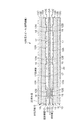
図1には、本実施形態に係る静電スピーカの断面図が示され、図2には、その分解図が示されている。これらの図において、音響装置としての静電スピーカ10は、振動膜11と、この振動膜11を両面側から挟む位置に積層された一対の固定極層12,12と、各固定極層12,12における振動膜11と反対側に設けられた一対の多孔質層13,13とを備えて構成されている。
FIG. 1 shows a sectional view of the electrostatic speaker according to the present embodiment, and FIG. 2 shows an exploded view thereof. In these drawings, an
前記振動膜11は、アルミニウム等の導電性を有する金属膜11Aと、この金属膜11Aの両面側にそれぞれ積層された帯電可能な一対の絶縁膜11B,11Bとにより構成されている。金属膜11Aには、静電スピーカ10から発生する音に対応する電気信号を入力する制御電極Aが接続されている。絶縁膜11Bは、例えば、PET樹脂の他、ポリプロピレン、ポリメチルペンテンもしくは環式オレフィンコポリマーを用いて構成される。
The
前記各固定極層12,12及び各多孔質層13,13は、振動膜11を挟んで図1中上下対称構造とされる。従って、以下では、同図中上側の固定極層12及び多孔質層13について説明するものとして同図中下側の各層12,13には同一符号を付して説明を省略する。
The fixed
前記固定極層12は、導電性を有する不織布により構成され、具体的には、不織布にアルミニウム等の金属材を含浸させたり、内面に金属材をスパッタリング若しくは蒸着させるたりすることにより構成される。前記不織布は、セルロース、ガラス繊維、鉱物繊維、金属繊維を用いて構成することができ、或いはプラスチックもしくは金属粉末を焼結させて構成することも例示できる。
The
固定極層12は、断面視で複数の凹凸が連続する形状に形成されている。換言すれば、固定極層12は、左右方向に沿って所定間隔毎に設けられるとともに、上方に凹むように形成された複数の凹み部12Aと、隣り合う凹み部12A間に位置するとともに、PET系等の接着剤層16を介して振動膜11に接着される被接着部12Bとを備えた形状とされる。凹み部12Aは、振動膜11との間に空隙部17を形成し、当該空隙部17内で振動膜11が振動できるようになっている。なお、固定極層12には、固定極層12に所定のバイアス電圧を与えるための固定電極Eが接続されている。
The
前記多孔質層13は、固定極層12にポリアミド系などの接着剤層18を介して積層され、当該接着剤層18から外側に向かって順次積層された中間層13A、接着剤層13B及び外側層13Cからなる。中間層13Aは、前記被接着部12Bに対応する領域が突出するように圧縮成型されている。中間層13A及び外側層13Cは、不織布を用いて構成され、振動膜11の振動により発生する音を透過しつつ、固定極層12に定形性を付与するようになっている。
The
前記多孔質層13における外側層13Cの外面には、撥水層20が設けられている。この撥水層20は、水が内側(振動膜11側)に向かって浸透することを防止しつつ、振動膜11からの音を透過する素材により構成される。
撥水層20としては、スプレー等を介して撥水材を塗布することが例示できる。この撥水材としては、フッ素樹脂、シリコン樹脂等の高分子材料が挙げられる。
また、撥水層20として、個々の単繊維の表面に前記撥水材を結合させた不織布も例示できる。前記単繊維は、一本一本の繊維の表面にフッ素樹脂が起毛状態に結合されたものであり、各繊維は、木質繊維、綿、羊毛、麻などの天然繊維、化学繊維、半合成繊維、或いはこれらを適宜組み合わせたものでもよい。用いるフッ素樹脂としては、ポリテトラフルオロエチレン(PTFE)、テトラフルオロエチレン−パーフルオロアルキルビニルエーテル共重合体(PFA)の他、テトラフルオロエチレン−ヘキサフルオロプロピレン共重合体(PFEP)、エチレン−テトラフルオロエチレン共重合体(PETFE)、エチレン−クロロトリフルオロエチレン共重合体(PECTFE)、ポリクロロトリフルオロエチレン(PCTFE)などが挙げられる。
更に、撥水層20は、フッ素樹脂を、空気を透過する多数の穴を備える多孔質構造の膜状に形成したものであってもよい。
A
Examples of the
Moreover, as the water
Furthermore, the water-
以上の構成において、固定電極Eに所定のバイアス電圧を与えるとともに、所定の制御装置(図示省略)を介して制御電極Aに電気信号を印加することにより、空隙部17内で振動膜11が振動する。この振動により、音が発生し、当該音が固定極層12,多孔質層13及び撥水層20を透過して放射されることとなる。
In the above configuration, a predetermined bias voltage is applied to the fixed electrode E and an electric signal is applied to the control electrode A via a predetermined control device (not shown), so that the
次に、本発明に係る効果を確認するため、以下の実施例を比較例と共に示す。 Next, in order to confirm the effect according to the present invention, the following examples are shown together with comparative examples.
[実施例]
実施例では、表1の条件に設定された図1に示される静電スピーカ10を用い、多孔質層13の外面側にパーフルオロアルキルアクリルレートを含む撥水材を塗布して撥水層20を形成した。
静電スピーカ10には、40℃、湿度90%の条件下で24時間放置した後、常温で24時間放置する耐湿放置を行った。
[Example]
In the embodiment, the
The

[比較例]
実施例に対し、撥水層20を有しない静電スピーカを用い、その他の条件は同一とした。
[Comparative example]
In contrast to the example, an electrostatic speaker without the
実施例と比較例の各静電スピーカに対して静電容量を測定した。静電容量を測定するタイミングは、未使用状態及び耐湿放置後とした。結果を表2及び図3に示す。
また、実施例と比較例の各静電スピーカに対して音響特性を無響室内において測定した。音響特性を測定するタイミングは、未使用状態及び耐湿放置後とした。結果を図4及び図5に示す。
Capacitance was measured for each of the electrostatic speakers of the example and the comparative example. The timing for measuring the capacitance was in an unused state and after being left with no moisture. The results are shown in Table 2 and FIG.
In addition, acoustic characteristics were measured in an anechoic chamber for each of the electrostatic speakers of the example and the comparative example. The timing for measuring the acoustic characteristics was in an unused state and after being left with no moisture. The results are shown in FIGS.
これらの図表から明らかなように、未使用状態と耐湿放置後とを比べると、実施例は、静電容量及び再生音圧共に殆ど変化していないのに対し、比較例は、静電容量及び再生音圧が共に低下している。これにより、実施例の構造が比較例に比べ、高音及び多湿の条件下においても、静電容量及び再生音圧の低下を回避でき、耐湿性能が向上していることが理解される。
なお、前述した実施例以外の条件、例えば、金属膜11Aの材質をアルミニウム以外の金属により構成したり、多孔質層13を中間層13Aの一層だけにより構成したりしても、前記実施例と同等の結果が得られることが期待される。
As is clear from these charts, when compared with the unused state and after being left with no moisture, in the example, both the capacitance and the reproduction sound pressure are hardly changed, whereas in the comparative example, the capacitance and Both playback sound pressures are decreasing. Accordingly, it is understood that the structure of the example can avoid the decrease in the capacitance and the reproduction sound pressure even under the condition of high sound and high humidity as compared with the comparative example, and the moisture resistance performance is improved.
Note that conditions other than those described above, for example, even if the material of the
本発明を実施するための最良の構成、方法などは、以上の記載で開示されているが、本発明は、これに限定されるものではない。
すなわち、本発明は、特定の実施の形態に関して特に図示し、且つ、説明されているが、本発明の技術的思想及び目的の範囲から逸脱することなく、以上に述べた実施例に対し、形状、位置若しくは方向、その他の詳細な構成において、当業者が様々な変形を加えることができるものである。
従って、上記に開示した形状などを限定した記載は、本発明の理解を容易にするために例示的に記載したものであり、本発明を限定するものではないから、それらの形状などの限定の一部若しくは全部の限定を外した部材の名称での記載は、本発明に含まれるものである。
Although the best configuration, method and the like for carrying out the present invention have been disclosed in the above description, the present invention is not limited to this.
That is, although the present invention has been particularly shown and described with respect to particular embodiments, it is to be understood that the invention has been shown to have the form described above without departing from the scope and spirit of the invention. Various modifications can be made by those skilled in the art in terms of position, orientation, and other detailed configurations.
Therefore, the description limited to the shape disclosed above is an example for easy understanding of the present invention, and does not limit the present invention. The description in the name of the member excluding a part or all of the limitation is included in the present invention.
前記静電スピーカ10は、振動膜11により音を再生でき、前述のような耐湿性能を発揮できる限りにおいて、種々の設計変更が可能である。例えば、前記実施形態の構造に対し、多孔質層13を省略して固定極層12の外側に撥水層20を設けたり、何れか一方の固定極層12を省略した構成としてもよい。また、撥水層20を、多孔質層13を形成する各層13A〜13Cの間や、多孔質層13と固定極層12との間に設けてもよい。
As long as the
また、図6に示されるように、撥水層20の外側に捕水層22を更に設けた構成も考えられる。この際、捕水層22は、水蒸気を吸収するとともに、その内部で前記水蒸気を水分子に変えることが可能な活性炭やシリカゲルなどの多孔質材料のような素材により構成される。これによれば、水蒸気が撥水層20に直接触れ難くなるばかりでなく、捕水した水分が経時的に乾燥して撥水層20が初期状態に略復帰するので、当該撥水層20による撥水効果をより良く得ることが可能となる。
Further, as shown in FIG. 6, a configuration in which a
更に、前記実施形態では、音響装置を静電スピーカ10としたが、制御電極Aを介して振動膜11の振動に対応する信号を測定する静電マイクとしてもよい。
Furthermore, in the above embodiment, the acoustic apparatus is the
10・・・静電スピーカ(音響装置)、11・・・振動膜、12・・・固定極層、13・・・多孔質層、17・・・空隙部、20・・・撥水層、22・・・捕水層
DESCRIPTION OF
Claims (5)
前記固定極層における振動膜と反対側に撥水層を設けたことを特徴とする音響装置。 In an acoustic device including a vibrating membrane and a conductive fixed pole layer laminated so as to include a gap between the vibrating membrane,
An acoustic device, wherein a water repellent layer is provided on a side of the fixed pole layer opposite to the vibration film.
前記固定極層より多孔質層側に撥水層を設けたことを特徴とする音響装置。 A vibration film, a pair of conductive fixed electrode layers disposed at positions sandwiching the vibration film from both sides, and laminated so as to include a gap between the vibration film, and each fixed electrode In the acoustic device including the porous layer provided on the opposite side of the vibrating membrane in the layer,
An acoustic device comprising a water repellent layer on the porous layer side of the fixed electrode layer.
Priority Applications (1)
| Application Number | Priority Date | Filing Date | Title |
|---|---|---|---|
| JP2004336843A JP2006148612A (en) | 2004-11-22 | 2004-11-22 | Acoustic device |
Applications Claiming Priority (1)
| Application Number | Priority Date | Filing Date | Title |
|---|---|---|---|
| JP2004336843A JP2006148612A (en) | 2004-11-22 | 2004-11-22 | Acoustic device |
Publications (2)
| Publication Number | Publication Date |
|---|---|
| JP2006148612A true JP2006148612A (en) | 2006-06-08 |
| JP2006148612A5 JP2006148612A5 (en) | 2007-12-13 |
Family
ID=36627774
Family Applications (1)
| Application Number | Title | Priority Date | Filing Date |
|---|---|---|---|
| JP2004336843A Pending JP2006148612A (en) | 2004-11-22 | 2004-11-22 | Acoustic device |
Country Status (1)
| Country | Link |
|---|---|
| JP (1) | JP2006148612A (en) |
Cited By (9)
| Publication number | Priority date | Publication date | Assignee | Title |
|---|---|---|---|---|
| JP2008227832A (en) * | 2007-03-12 | 2008-09-25 | Yamaha Corp | Electrostatic speaker |
| JP2009188516A (en) * | 2008-02-04 | 2009-08-20 | Yamaha Corp | Electrostatic loudspeaker |
| JP2009278479A (en) * | 2008-05-16 | 2009-11-26 | Foster Electric Co Ltd | Electrostatic loudspeaker |
| JP2010068053A (en) * | 2008-09-08 | 2010-03-25 | Yamaha Corp | Electrostatic speaker |
| JP2011244479A (en) * | 2011-08-01 | 2011-12-01 | Yamaha Corp | Electrostatic speaker |
| WO2012005369A1 (en) * | 2010-07-09 | 2012-01-12 | ヤマハ株式会社 | Electrostatic loudspeaker |
| JP2012019476A (en) * | 2010-07-09 | 2012-01-26 | Yamaha Corp | Electrostatic speaker |
| JP2012023559A (en) * | 2010-07-14 | 2012-02-02 | Yamaha Corp | Electrostatic speaker |
| US8502062B2 (en) | 2010-07-12 | 2013-08-06 | Yamaha Corporation | Electronic keyboard musical instrument |
Citations (6)
| Publication number | Priority date | Publication date | Assignee | Title |
|---|---|---|---|---|
| JPS609300A (en) * | 1983-06-29 | 1985-01-18 | Toshiba Corp | Electrostatic type electroacoustic transducer and its manufacture |
| JPS6174498A (en) * | 1984-09-20 | 1986-04-16 | Toshiba Corp | Electrostatic electroacoustic transducer |
| JPH05308784A (en) * | 1992-04-28 | 1993-11-19 | Mitsubishi Kasei Corp | Electrostatic actuator |
| JP2002513263A (en) * | 1998-04-27 | 2002-05-08 | パンフォニクス オーワイ | Acoustic element |
| JP2004526384A (en) * | 2001-04-11 | 2004-08-26 | パンフォニクス オイ | Electromechanical converter and method of converting energy |
| JP2004527283A (en) * | 2001-02-14 | 2004-09-09 | インテリマッツ・エルエルシー | Floor mat with voice response display |
-
2004
- 2004-11-22 JP JP2004336843A patent/JP2006148612A/en active Pending
Patent Citations (6)
| Publication number | Priority date | Publication date | Assignee | Title |
|---|---|---|---|---|
| JPS609300A (en) * | 1983-06-29 | 1985-01-18 | Toshiba Corp | Electrostatic type electroacoustic transducer and its manufacture |
| JPS6174498A (en) * | 1984-09-20 | 1986-04-16 | Toshiba Corp | Electrostatic electroacoustic transducer |
| JPH05308784A (en) * | 1992-04-28 | 1993-11-19 | Mitsubishi Kasei Corp | Electrostatic actuator |
| JP2002513263A (en) * | 1998-04-27 | 2002-05-08 | パンフォニクス オーワイ | Acoustic element |
| JP2004527283A (en) * | 2001-02-14 | 2004-09-09 | インテリマッツ・エルエルシー | Floor mat with voice response display |
| JP2004526384A (en) * | 2001-04-11 | 2004-08-26 | パンフォニクス オイ | Electromechanical converter and method of converting energy |
Cited By (11)
| Publication number | Priority date | Publication date | Assignee | Title |
|---|---|---|---|---|
| JP2008227832A (en) * | 2007-03-12 | 2008-09-25 | Yamaha Corp | Electrostatic speaker |
| JP2009188516A (en) * | 2008-02-04 | 2009-08-20 | Yamaha Corp | Electrostatic loudspeaker |
| JP2009278479A (en) * | 2008-05-16 | 2009-11-26 | Foster Electric Co Ltd | Electrostatic loudspeaker |
| JP2010068053A (en) * | 2008-09-08 | 2010-03-25 | Yamaha Corp | Electrostatic speaker |
| WO2012005369A1 (en) * | 2010-07-09 | 2012-01-12 | ヤマハ株式会社 | Electrostatic loudspeaker |
| JP2012019476A (en) * | 2010-07-09 | 2012-01-26 | Yamaha Corp | Electrostatic speaker |
| KR101445503B1 (en) * | 2010-07-09 | 2014-09-26 | 야마하 가부시키가이샤 | Electrostatic loudspeaker |
| US8885853B2 (en) | 2010-07-09 | 2014-11-11 | Yamaha Corporation | Electrostatic loudspeaker |
| US8502062B2 (en) | 2010-07-12 | 2013-08-06 | Yamaha Corporation | Electronic keyboard musical instrument |
| JP2012023559A (en) * | 2010-07-14 | 2012-02-02 | Yamaha Corp | Electrostatic speaker |
| JP2011244479A (en) * | 2011-08-01 | 2011-12-01 | Yamaha Corp | Electrostatic speaker |
Similar Documents
| Publication | Publication Date | Title |
|---|---|---|
| KR101942133B1 (en) | Microphone device, microphone unit, microphone structure, and electronic equipment using these | |
| JP2006148612A (en) | Acoustic device | |
| KR101490868B1 (en) | Waterproof sound-transmitting sheet and manufacturing thereof | |
| US10531203B2 (en) | Acoustic apparatus and associated methods | |
| JP3160271B2 (en) | Piezoelectric speaker, method of manufacturing the same, and speaker system | |
| JP2013172391A (en) | Single directional capacitor microphone and acoustic resistance adjustment method of the same | |
| CN109379684A (en) | Microphone and electronic equipment | |
| JP4527282B2 (en) | Acoustic element | |
| US20100111335A1 (en) | Electronic device with electret electro-acoustic transducer | |
| JP2005334758A (en) | Ventilation filter | |
| JP4163377B2 (en) | Piezoelectric speaker and speaker system | |
| KR101370581B1 (en) | Membrane Assembly | |
| JP5054749B2 (en) | Electronic device with electret electroacoustic transducer | |
| TW201311015A (en) | Electret loudspeaker device | |
| JPS60157399A (en) | Condenser microphone | |
| JP2001148897A (en) | Waterproof electroacoustic transducer | |
| JP6577681B2 (en) | Soundproof structure | |
| JP2007037069A (en) | Humidity-resistant electret capacitor microphone | |
| KR100697350B1 (en) | Hybrid speaker | |
| JP5518511B2 (en) | Condenser headphone unit | |
| JP6675914B2 (en) | Stereo microphone | |
| JP2002186075A (en) | Waterproof electroacoustic transducer | |
| JP2009011730A (en) | Hearing protection device | |
| Wegener et al. | Voided space-charge electrets? Piezoelectric transducer materials for electro-acoustic applications | |
| JP5475070B2 (en) | Contact microphone |
Legal Events
| Date | Code | Title | Description |
|---|---|---|---|
| A521 | Written amendment |
Effective date: 20071031 Free format text: JAPANESE INTERMEDIATE CODE: A523 |
|
| A621 | Written request for application examination |
Effective date: 20071031 Free format text: JAPANESE INTERMEDIATE CODE: A621 |
|
| A977 | Report on retrieval |
Free format text: JAPANESE INTERMEDIATE CODE: A971007 Effective date: 20100524 |
|
| A131 | Notification of reasons for refusal |
Effective date: 20100601 Free format text: JAPANESE INTERMEDIATE CODE: A131 |
|
| A02 | Decision of refusal |
Free format text: JAPANESE INTERMEDIATE CODE: A02 Effective date: 20101026 |