JP2006121952A - Combine harvester - Google Patents
Combine harvester Download PDFInfo
- Publication number
- JP2006121952A JP2006121952A JP2004313130A JP2004313130A JP2006121952A JP 2006121952 A JP2006121952 A JP 2006121952A JP 2004313130 A JP2004313130 A JP 2004313130A JP 2004313130 A JP2004313130 A JP 2004313130A JP 2006121952 A JP2006121952 A JP 2006121952A
- Authority
- JP
- Japan
- Prior art keywords
- cereal
- line
- stock
- automatic
- control
- Prior art date
- Legal status (The legal status is an assumption and is not a legal conclusion. Google has not performed a legal analysis and makes no representation as to the accuracy of the status listed.)
- Withdrawn
Links
Images


Abstract
Description
本発明は、コンバインの特に、方向制御に係るものである。 The present invention particularly relates to directional control of a combine.
従来、左右一対のクローラを有する走行装置の前方に設け刈取部を設け、刈取部に設けた圃場の穀稈に接触する方向センサの信号によって、機体の走行方向を修正するようにした構成は、公知である(特許文献1参照)。
また、従来、機体後部に機体後方を撮影する後方撮影機材を設け、後方撮影機材の映像を操縦部のモニタに表示するようにした構成は、公知である(特許文献2参照)。
Conventionally, a configuration in which a rear photographing device for photographing the rear of the aircraft is provided at the rear of the aircraft, and an image of the rear photographing device is displayed on a monitor of the control unit is known (see Patent Document 2).
前記公知例のうち前者は、圃場の穀稈にセンサが接触しながら所定距離走行することにより、センサの接触回数をカウントし、機体がどのようにずれているか測定する方式のため、倒伏穀稈の場合、本来センサに接触する穀稈の株元の株以外の倒伏穀稈の途中部分がセンサに接触し、正確な方向制御ができないという課題がある。
前記公知例のうち後者は、機体後方をモニタにより視認するのみで、走行方向の修正はできない。
本願は、接触式の方向センサでは難しい状況でも、自動方向制御機構できるようにしたものである。
Among the known examples, the former is a method of counting the number of times the sensor is touched by traveling a predetermined distance while the sensor is in contact with the rice straw in the field, and measuring how the machine is displaced. In this case, there is a problem that accurate direction control cannot be performed because the middle part of the lodging cereal other than the original strain of the cereal that contacts the sensor contacts the sensor.
Of the known examples, the latter only visually recognizes the rear of the aircraft with a monitor and cannot correct the traveling direction.
The present application is intended to enable an automatic direction control mechanism even in a situation difficult with a contact-type direction sensor.
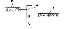
本発明は、左右一対のクローラ3を有する走行装置2と、前記走行装置2の前方に設けた圃場の穀稈を刈取搬送する刈取部5とを有し、該刈取部5は、圃場の株列Kと株列Kの間の株間を各分草体10が通るように、自動方向制御機構Sにより方向修正しながら走行するように構成し、前記自動方向制御機構Sは、前記脱穀装置4あるいはグレンタンク6等の任意の機体後部に設けた後方撮影機材15による撮影した画像により、前記刈取部5が既に切断した穀稈の株列Kを認識し、この株列Kと機体とのずれを検出して方向制御を行うように構成したコンバインとしたものであり、刈取部5の分草体10を、圃場の株と株の間の株間に合わせ、所定距離走行すると、刈取部5が刈り取った穀稈の株列Kが機体後方に現れ、これを後方撮影機材15が撮影し、後方撮影機材15による撮影した画像により制御部16は、刈取部5が既に切断した穀稈の株列Kを認識し、この株列Kと機体とのズレθを検出し、機体の走行方向を自動的に修正する制御を行って、走行する。
本発明は、前記後方撮影機材15は、操縦部7に設けた表示モニタ20へ機体後方画像信号を送出可能に構成したコンバインとしたものであり、表示切替スイッチにより切替えることにより後方撮影機材15の情報により操縦部7に設けた表示モニタ20に、機体後方画像を表示し、作業者は機体後方の状態を視認する。
本発明は、前記後方撮影機材15の機体後方画像信号から、前記クローラ3の沈下量を判別し、その結果により方向修正の出力値を変更するように構成したコンバインとしたものであり、後方撮影機材15の機体後方画像信号からクローラ3の沈下量を判別し、その結果により方向修正の出力値を変更する。
本発明は、前記後方撮影機材15の機体後方画像信号により横刈りになると判定したとき、自動方向制御を行わないように構成したコンバインとしたものであり、後方撮影機材15の画像信号から株の間隔の広狭により生じる画像濃度の相違等を認識して条刈りと横刈りの判別を行い、横刈りと判定したときには、自動的に方向制御を停止させる。
The present invention includes a
In the present invention, the rear
The present invention is a combine configured to discriminate the amount of subsidence of the
The present invention is a combine that is configured not to perform automatic direction control when it is determined that the horizontal cutting is performed based on the rear image signal of the aircraft body of the
請求項1の発明では、倒伏穀稈のような接触式の方向センサで方向制御できないようなときでも、自動的に走行方向制御可能になるので、作業効率が向上し、制御精度を向上できる。
請求項2の発明では、機体後方の状態を表示モニタ20により視認可能にすると共に、一つの後方撮影機材15からの画像により後方視認と方向制御の二つが可能となり、合理的構成となって、安価にできる。
請求項3の発明では、湿田における方向制御精度を向上させることができる。
請求項4の発明では、条横刈りの判定を後方撮影機材15により行って、自動的に方向制御を「入り切り」でき、操作性を向上させる。
According to the first aspect of the present invention, even when the direction cannot be controlled by a contact-type direction sensor such as a fallen cedar, the traveling direction can be automatically controlled, so that the working efficiency can be improved and the control accuracy can be improved.
In the invention of
In the invention of
According to the fourth aspect of the present invention, it is possible to perform the on / off control of the direction automatically by performing the determination of the horizontal cutting of the strips with the
本発明の実施例を図面により説明すると、1はコンバインの機体フレーム、2は左右一対のクローラ3を有する走行装置、4は機体フレーム1の上方に設けた脱穀装置、5は脱穀装置4の前側に設けた刈取部、6は脱穀装置4の側部に設けたグレンタンク、7はグレンタンク6の前方に設けた操縦部、8は運転席である。
刈取部5は、公知のものであり、詳細は省略するが、最前方位置に分草体10を設け、分草体10の後側には分草体10で分草した穀稈を引き起こす引起装置引起装置を設け、引起装置の後側には引き起こした穀稈の株元切断する刈刃を設け、刈刃の後方には刈り取られた穀稈を搬送する穀稈搬送装置(図示省略)を設けている。
An embodiment of the present invention will be described with reference to the drawings. Reference numeral 1 denotes a combiner body frame, 2 a traveling device having a pair of left and
The
しかして、前記走行装置2は、左右のクローラ3に伝達する回転を制御して方向変換するが、前記刈取部5は、圃場の株と株の間の株間を各分草体10が通るように、最初に、分草体10を株間に合わせて所定距離走行し、その後、圃場の株列Kに合わせて、自動方向制御機構Sにより前進するように構成する。
自動方向制御機構Sは、前記脱穀装置4あるいはグレンタンク6等の任意のコンバインの後部に設けた後方撮影機材(カメラ・CCD)15が撮影した画像により、刈取部5が既に切断した穀稈の株列Kを認識し、この株列Kと機体(分草体10) とのずれを検出し、機体の方向制御を行うように構成する。
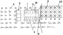
即ち、図3は、脱穀装置等を省略して左右のクローラ3を機体として表示しており、図3に示した直線が機体進行方向の基準となる機体方向ラインLであり、この機体方向ラインLと、後方撮影機材15が撮影した株列Kの内の任意の株列Kとのズレθを検出し、このズレθを修正することにより、方向制御を行う(図4)。
したがって、従来の穀稈接触式の方向センサでは、倒伏穀稈の場合、株列Kと倒伏穀稈の穂先部分との判別が容易でなく、不正確な方向制御となっていたが、本願では倒伏穀稈のような場合でも正確な方向制御が行える。
16は制御部である。
Thus, the
The automatic directional control mechanism S is used for the cereals that have already been cut by the reaping
That is, FIG. 3 omits the threshing device and the like and displays the left and
Therefore, in the conventional corn straw contact-type direction sensor, in the case of the fallen cereal, it was not easy to distinguish between the stock line K and the tip of the fallen cereal, and the direction control was incorrect. Accurate direction control is possible even in the case of a fallen cereal.
この場合、複数の株列Kの設定区間の株列Kが作る直線方向を演算し、その直線と機体方向ラインLとのズレθを少なくするように方向修正するように構成する。
この場合、機体走行方向に対して交差方向に複数の株列Kのうち、最も未刈地側に寄った株列Kとのズレθを修正するように方向制御を行うと、後述のカッター装置18により排出する切り藁の排出面積を広くでき(図5)、好適である。
In this case, the straight line direction formed by the stock line K in the set section of the plurality of stock lines K is calculated, and the direction is corrected so as to reduce the deviation θ between the straight line and the machine direction line L.
In this case, when direction control is performed so as to correct the deviation θ from the stock line K that is closest to the uncut land among the multiple stock lines K in the crossing direction with respect to the aircraft traveling direction, a cutter device that will be described later The discharge area of the cutting waste discharged by 18 can be widened (FIG. 5), which is preferable.
しかして、前記後方撮影機材15は、操縦部7に設けた表示モニタ20へ機体後方画像信号を送出可能に構成すると、一つの後方撮影機材15により後方画像および方向制御用の画像信号が得られるようになり、合理的構成となって、安価にできる。
Thus, when the
また、前記後方撮影機材15の機体後方画像信号から、前記クローラ3の沈下量を判別し、その結果により方向修正の出力値を変更するように構成すると、湿田における方向制御精度を向上させることができ、好適である。
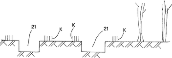
例えば、乾田であれば、図5のように、一面に切り藁が拡散されるが、湿田では図6のようにクローラ3の踏み後がわだち21となって撮影される。
即ち、圃場における走行中、圃場の状態により左右のクローラ3のスリップ率が相違して、機体が直進走行から旋回したり、あるいは、旋回半径が変化するが、後方撮影機材15からの画像によりクローラ3の沈下量を判別して方向修正の出力値を変更できるので、方向制御精度を向上させられる。
Further, by determining the amount of subsidence of the
For example, in the case of a dry paddy, the cut rice cake is diffused over the entire surface as shown in FIG. 5, but in the wet paddy field, a
That is, while traveling in the field, the slip rate of the left and
しかして、前記後方撮影機材15の機体後方画像信号により方向制御は、所謂条刈りのとき行い、後方撮影機材15の機体後方画像信号により横刈りになると判定したときには、自動方向制御機構Sによる制御を行わない(オフ)ように構成する。
即ち、条刈に比し横刈では株列Kは乱れ易く、後方撮影機材15による方向制御は困難なので、自動方向制御機構Sによる制御を行わず、自動的に自動方向制御を停止させる。
したがって、圃場の穀稈群のうち一辺を刈り取る度に条刈と横刈との移行が行われるが、このとき、一々切替操作する必要がなく、自動的に、条横判定を後方撮影機材15の画像により行い、しかも、条刈りのときは自動的に方向制御を行うので、操作性が向上する。
Therefore, the direction control by the rear image signal of the
That is, the stock row K is more likely to be disturbed by the horizontal cutting compared to the row cutting, and the direction control by the
Therefore, every time one side of the grain culm group in the field is cut, transition between row cutting and side cutting is performed. At this time, it is not necessary to perform switching operation one by one, and the horizontal row determination is automatically performed in the
しかして、脱穀装置4の後方に脱穀した排藁を切断する前記カッター装置18を設けているが、カッター装置18の切り藁が、条方向に連続しない株列Kを作り、この後方撮影機材15の画像認識と前記機体方向ラインLとのズレθにより自動方向修正するように構成する。
したがって、確実に切り藁が乗らない既刈株列Kを作り、確実に株列Kの画像認識と機体方向ラインLとのズレθにより自動方向修正できる。
Thus, although the
Therefore, it is possible to make an already cut stock row K on which the cutting bar does not ride reliably, and to automatically correct the direction by the deviation θ between the image recognition of the stock row K and the machine direction line L.
この場合、条方向に連続しない株列Kは、機体進行方向に向かって最も左側の条とすると(図8)、自動方向制御を確実にするだけでなく、次回の刈取作業で、この後方撮影機材15の画像認識用の株列K上に切り藁を拡散させることができ、その結果、切り藁を圃場全体に均一に分散できる。
即ち、一条の株列Kにより自動方向制御を行いつつ、次の刈取作業のときにこの株列Kの上にも切り藁を乗せるので、全面に分散できる。
In this case, if the stock line K that is not continuous in the direction of the line is the leftmost line in the aircraft traveling direction (FIG. 8), not only will the automatic direction control be ensured, but also this rear shot will be performed in the next cutting operation. The cuttings can be diffused on the stock line K for image recognition of the
That is, the automatic directional control is performed by the single stock row K, and the cutting rod is placed on the stock row K at the time of the next cutting operation, so that the entire surface can be dispersed.
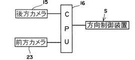
しかして、前記刈取部5または操縦部7等の任意箇所に前記前方撮影機材23を設け、前方最も左側の条の株列Kを前方撮影機材23により画像認識し、その前方撮影機材23で複数株列Kの設定区間の株列Kが作る直線方向を演算し、前記後方撮影機材15および前方撮影機材23の両方で演算した株列Kの直線方向と機体方向ラインLとのズレθを測定し、このズレθを少なくするように方向修正するように構成する。
したがって、高精度の画像認識による方向制御を行うことができる。
Thus, the
Therefore, it is possible to perform direction control by high-accuracy image recognition.
しかして、前記後方撮影機材15および前方撮影機材23の夫々が複数株列Kの設定区間の株列Kが作る直線方向を演算し、前記後方撮影機材15および前方撮影機材23の両方で演算した株列Kの直線方向のうち、機体方向ラインLに対するズレθが大きい方の株列Kを基準に、株列Kと機体方向ラインLとのズレθが少なくするように方向修正するように構成する。
したがって、高精度の画像認識による方向制御を行うことができる。
Thus, each of the
Therefore, it is possible to perform direction control by high-accuracy image recognition.
1…機体フレーム、2…走行装置、3…クローラ、4…脱穀装置、5…刈取部、6…グレンタンク、7…操縦部、8…運転席、10…分草体、15…後方撮影機材、16…制御部、18…カッター装置、20…表示モニタ、21…わだち、23…前方撮影機材。 DESCRIPTION OF SYMBOLS 1 ... Airframe frame, 2 ... Traveling device, 3 ... Crawler, 4 ... Threshing device, 5 ... Mowing part, 6 ... Glen tank, 7 ... Control part, 8 ... Driver's seat, 10 ... Herbaceous body, 15 ... Rear photography equipment, 16 ... Control unit, 18 ... Cutter device, 20 ... Display monitor, 21 ... Waddle, 23 ... Front photography equipment.
Claims (4)
Priority Applications (1)
| Application Number | Priority Date | Filing Date | Title |
|---|---|---|---|
| JP2004313130A JP2006121952A (en) | 2004-10-27 | 2004-10-27 | Combine harvester |
Applications Claiming Priority (1)
| Application Number | Priority Date | Filing Date | Title |
|---|---|---|---|
| JP2004313130A JP2006121952A (en) | 2004-10-27 | 2004-10-27 | Combine harvester |
Publications (2)
| Publication Number | Publication Date |
|---|---|
| JP2006121952A true JP2006121952A (en) | 2006-05-18 |
| JP2006121952A5 JP2006121952A5 (en) | 2007-11-08 |
Family
ID=36717253
Family Applications (1)
| Application Number | Title | Priority Date | Filing Date |
|---|---|---|---|
| JP2004313130A Withdrawn JP2006121952A (en) | 2004-10-27 | 2004-10-27 | Combine harvester |
Country Status (1)
| Country | Link |
|---|---|
| JP (1) | JP2006121952A (en) |
Cited By (5)
| Publication number | Priority date | Publication date | Assignee | Title |
|---|---|---|---|---|
| WO2016076320A1 (en) * | 2014-11-13 | 2016-05-19 | ヤンマー株式会社 | Field state detection system |
| KR20200014735A (en) | 2017-06-23 | 2020-02-11 | 가부시끼 가이샤 구보다 | harvest |
| WO2020262287A1 (en) * | 2019-06-28 | 2020-12-30 | 株式会社クボタ | Farm operation machine, autonomous travel system, program, recording medium in which program is recorded, and method |
| JP2021007385A (en) * | 2019-06-28 | 2021-01-28 | 株式会社クボタ | Farm implement |
| JP2022516898A (en) * | 2018-12-29 | 2022-03-03 | 豊疆智能科技股▲ふん▼有限公司 | Harvester and its automatic driving method |
-
2004
- 2004-10-27 JP JP2004313130A patent/JP2006121952A/en not_active Withdrawn
Cited By (6)
| Publication number | Priority date | Publication date | Assignee | Title |
|---|---|---|---|---|
| WO2016076320A1 (en) * | 2014-11-13 | 2016-05-19 | ヤンマー株式会社 | Field state detection system |
| KR20200014735A (en) | 2017-06-23 | 2020-02-11 | 가부시끼 가이샤 구보다 | harvest |
| JP2022516898A (en) * | 2018-12-29 | 2022-03-03 | 豊疆智能科技股▲ふん▼有限公司 | Harvester and its automatic driving method |
| WO2020262287A1 (en) * | 2019-06-28 | 2020-12-30 | 株式会社クボタ | Farm operation machine, autonomous travel system, program, recording medium in which program is recorded, and method |
| JP2021007385A (en) * | 2019-06-28 | 2021-01-28 | 株式会社クボタ | Farm implement |
| CN113766826A (en) * | 2019-06-28 | 2021-12-07 | 株式会社久保田 | Agricultural working machine, automatic travel system, program, recording medium having program recorded thereon, and method |
Similar Documents
| Publication | Publication Date | Title |
|---|---|---|
| CN110621152B (en) | Feeder and header positioning method | |
| WO2014093814A1 (en) | Predictive load estimation through forward vision | |
| US10420284B2 (en) | Slip controller for side conveyors of a draper harvesting head | |
| JP6499570B2 (en) | Stem number measuring system and farming management system using it | |
| JP7381402B2 (en) | automatic driving system | |
| JP6883974B2 (en) | Yield distribution calculation device and yield distribution calculation program | |
| CN113766824A (en) | Harvester, obstacle determination program, recording medium having obstacle determination program recorded thereon, obstacle determination method, agricultural machine, control program, recording medium having control program recorded thereon, and control method | |
| JP2006121952A (en) | Combine harvester | |
| WO2021261343A1 (en) | Harvester, system for controlling harvester, method for controlling harvester, program for controlling harvester, and storage medium | |
| JP2006121952A5 (en) | ||
| US20220212602A1 (en) | Harvester, System, Program, Recording Medium, and Method | |
| JP2021007385A (en) | Farm implement | |
| EP3000304A1 (en) | Agregate yield allocation | |
| WO2020262287A1 (en) | Farm operation machine, autonomous travel system, program, recording medium in which program is recorded, and method | |
| WO2020218528A1 (en) | Agricultural machine such as harvester | |
| JP7423441B2 (en) | harvester | |
| JP2019097412A (en) | Automatic travel control device of combine | |
| JP7423440B2 (en) | harvester | |
| JP2020178617A (en) | Harvester | |
| JPH082730Y2 (en) | Harvester automatic steering device | |
| JP7433145B2 (en) | harvester | |
| JP3812029B2 (en) | Depth control device for combine etc. | |
| JP2009201399A (en) | Direction control mechanism of combine harvester | |
| JP2513374Y2 (en) | Harvester automatic steering device | |
| JP6670165B2 (en) | Harvester |
Legal Events
| Date | Code | Title | Description |
|---|---|---|---|
| A521 | Written amendment |
Free format text: JAPANESE INTERMEDIATE CODE: A523 Effective date: 20070926 |
|
| A300 | Withdrawal of application because of no request for examination |
Free format text: JAPANESE INTERMEDIATE CODE: A300 Effective date: 20080108 |