JP2006120878A - Liquid-immersion exposure device and device manufacturing method using the same - Google Patents
Liquid-immersion exposure device and device manufacturing method using the same Download PDFInfo
- Publication number
- JP2006120878A JP2006120878A JP2004307528A JP2004307528A JP2006120878A JP 2006120878 A JP2006120878 A JP 2006120878A JP 2004307528 A JP2004307528 A JP 2004307528A JP 2004307528 A JP2004307528 A JP 2004307528A JP 2006120878 A JP2006120878 A JP 2006120878A
- Authority
- JP
- Japan
- Prior art keywords
- liquid
- substrate
- exposure apparatus
- reducing agent
- optical system
- Prior art date
- Legal status (The legal status is an assumption and is not a legal conclusion. Google has not performed a legal analysis and makes no representation as to the accuracy of the status listed.)
- Withdrawn
Links
Images


Landscapes
- Exposure And Positioning Against Photoresist Photosensitive Materials (AREA)
- Exposure Of Semiconductors, Excluding Electron Or Ion Beam Exposure (AREA)
Abstract
Description
本発明は、一般に露光装置に関し、特に、半導体デバイスを製造する際のリソグラフィー工程において基板にデバイスパターンを露光転写するための液浸露光装置、及びそれを用いたデバイス製造方法に関するものである。 The present invention generally relates to an exposure apparatus, and more particularly, to an immersion exposure apparatus for exposing and transferring a device pattern onto a substrate in a lithography process when manufacturing a semiconductor device, and a device manufacturing method using the same.
近年、半導体デバイスの微細化への要求はますます高くなっており、投影露光装置に対する解像力向上の要求は高くなっている。投影露光装置の解像力を向上させるために、投影レンズの高NA化と、露光光の波長の短波長化が近年ますます加速している。その短波長化はKrFエキシマレーザを光源とした248nmから、ArFエキシマレーザを光源とした193nmへと進んでいる。 In recent years, the demand for miniaturization of semiconductor devices is increasing, and the demand for improving the resolution of projection exposure apparatuses is increasing. In order to improve the resolving power of the projection exposure apparatus, a higher NA of the projection lens and a shorter wavelength of the exposure light have been accelerated in recent years. The shortening of the wavelength has progressed from 248 nm using a KrF excimer laser as a light source to 193 nm using an ArF excimer laser as a light source.
一方、光学式顕微鏡の解像力を向上させる技術のひとつに、対物レンズと観察試料間の間に高屈折率の液体を充填する液浸法がある。 On the other hand, one technique for improving the resolution of an optical microscope is an immersion method in which a liquid with a high refractive index is filled between an objective lens and an observation sample.
この効果を半導体デバイスの微細化のために応用する提案もされており(例えば、特許文献1参照。)、投影光学系の最もウエハ側のレンズ(最終レンズ)とウエハとの間を空気よりも屈折率nの高い液体で満たすことにより、空気中での波長の1/nの波長の光を露光光として使用するの同じ効果を得ることができる液浸露光装置が提案されている(特許文献2参照。)。
従来から、露光光の波長が短くなり露光光のエネルギーが大きくなると、露光光が、露光装置の硝材(レンズやミラー等)、及びその硝材に成膜された反射防止膜、硝材の周りの部材等にダメージを与えることは知られていた。 Conventionally, when the wavelength of the exposure light is shortened and the energy of the exposure light is increased, the exposure light is converted into a glass material (lens, mirror, etc.) of the exposure apparatus, an antireflection film formed on the glass material, and members around the glass material. It was known to cause damage.
しかし、本発明者の検討の結果、液浸露光装置の場合には、従来の液浸法を用いないドライ系の露光装置に比べて、より大きなダメージが、特に最終レンズ、最終レンズ回りの部材、ウエハ、ウエハ回りの部材(ウエハを保持するための部材等)に発生することが判明した。そして、そのダメージは露光波長が短くなるにつれ顕著となる。 However, as a result of the inventor's investigation, in the case of an immersion exposure apparatus, the damage is greater than that of a dry exposure apparatus that does not use a conventional immersion method, particularly the final lens and members around the final lens. It has been found that this occurs in the wafer and members around the wafer (members for holding the wafer, etc.). The damage becomes more prominent as the exposure wavelength becomes shorter.
このようなダメージの発生により、露光装置の解像性能が若干低下したり、硝材の交換を頻繁に行わなければならないためスループットが悪化したりするという問題が発生しかねない。 Due to the occurrence of such damage, there may be a problem that the resolution performance of the exposure apparatus is slightly lowered, and the glass material must be replaced frequently, so that the throughput is deteriorated.
そこで、本発明の例示的な目的は、より長期に安定した性能を維持することが可能な液浸露光装置を提供することにある。 Accordingly, an exemplary object of the present invention is to provide an immersion exposure apparatus capable of maintaining stable performance for a longer period of time.
上記目的を達成するために、本発明の一側面としての液浸露光装置は、レチクルのパターンを基板に投影する投影光学系と、前記投影光学系と前記基板の間の少なくとも一部に液体を供給する供給部とを備える液浸露光装置において、前記液体に還元剤を導入する装置を有することを特徴とする。 In order to achieve the above object, an immersion exposure apparatus according to one aspect of the present invention includes a projection optical system that projects a reticle pattern onto a substrate, and a liquid that is applied to at least a portion between the projection optical system and the substrate. An immersion exposure apparatus comprising a supply unit for supplying a supply unit, wherein the apparatus includes a device for introducing a reducing agent into the liquid.
また、本発明の一側面としてのデバイス製造方法は、上記液浸露光装置を用いて基板を露光するステップと、該露光された基板を現像するステップと、を有することを特徴とする。 A device manufacturing method according to one aspect of the present invention includes a step of exposing a substrate using the immersion exposure apparatus, and a step of developing the exposed substrate.
更に、本発明の一側面としての露光システムは、レチクルのパターンを基板に投影する投影光学系と、前記投影光学系と前記基板の間の少なくとも一部に液体を供給する供給部とを有する液浸露光装置と、前記液体に前記還元剤を導入する装置とを備えることを特徴とする。 Furthermore, an exposure system according to an aspect of the present invention includes a projection optical system that projects a reticle pattern onto a substrate, and a liquid supply unit that supplies liquid to at least a part between the projection optical system and the substrate. An immersion exposure apparatus and an apparatus for introducing the reducing agent into the liquid are provided.
更に、本発明の一側面としての露光方法は、レチクルのパターンを基板に投影する投影光学系と該基板の間の少なくとも一部に満たされた液体を介して該基板を露光する露光方法において、前記液体に還元剤を導入するステップを有することを特徴とする。 Furthermore, an exposure method according to one aspect of the present invention is an exposure method in which the substrate is exposed via a projection optical system that projects a reticle pattern onto the substrate and a liquid filled in at least a portion between the substrates. It has a step of introducing a reducing agent into the liquid.
本発明の更なる目的又はその他の特徴は、以下、添付の図面を参照して説明される好ましい実施例等によって明らかにされるであろう。 Further objects and other features of the present invention will be made clear by the preferred embodiments described below with reference to the accompanying drawings.
従来よりも、長期に安定した性能を維持することが可能な液浸露光装置を提供することができる。 It is possible to provide an immersion exposure apparatus that can maintain stable performance for a long period of time compared to the prior art.
液浸露光装置においては、投影光学系の最も基板側の光学素子(最終レンズ)と基板との間に満たす液体(液浸用液体)として、空気よりも屈折率の高い液体を用いる。しかし、その液浸用液体として水・水溶液を採用する場合にはH2OのOとしてO(酸素元素)を含有し、有機系の液体を採用する場合でも、その構造の中にOが含有されているものが多い。また、液浸用液体自体はOを有さなくても、液浸用液体へ大気中の酸素が混入して酸素を含有している場合もある。 In the immersion exposure apparatus, a liquid having a refractive index higher than that of air is used as a liquid (immersion liquid) filled between the optical element (final lens) on the most substrate side of the projection optical system and the substrate. However, when water or an aqueous solution is used as the immersion liquid, O (oxygen element) is contained as O in H 2 O, and even when an organic liquid is used, O is contained in the structure. There are many that have been done. Further, even if the immersion liquid itself does not have O, oxygen in the atmosphere may be mixed into the immersion liquid and contain oxygen.
従って、液浸用液体として酸素を含有する液体(Oを含有する液体を含む)を使用した場合、ウエハ露光時には、最終レンズとウエハとの間には、酸素を含有する液体と露光光が同時に存在することとなる。 Accordingly, when a liquid containing oxygen (including a liquid containing O) is used as the immersion liquid, the liquid containing oxygen and the exposure light are simultaneously placed between the final lens and the wafer during wafer exposure. Will exist.
そして、本発明者の更なる鋭意検討の結果、前述した液浸露光装置において発生する最終レンズ、最終レンズ回りの部材、ウエハ又はウエハ回りの部材のダメージは、その「最終レンズとウエハとの間に酸素を含有する液体と露光光が同時に存在すること」に起因することが判明した。 As a result of further diligent examination by the inventor, the damage of the final lens, the member around the final lens, the wafer or the member around the wafer generated in the above-described immersion exposure apparatus is “between the final lens and the wafer. It has been found that this is caused by the fact that a liquid containing oxygen and exposure light exist simultaneously.
酸素を含有する液体と光とが同時に存在する場合、光により液体及び液体中の酸素が励起され、非常に酸化力の強い励起種が発生する。その励起種の酸化力により、各部材が変性し、その性能を維持できなくなったり、パーティクル発生の原因となったりするのである。 In the case where a liquid containing oxygen and light are present at the same time, the liquid and oxygen in the liquid are excited by light, and excited species having a very strong oxidizing power are generated. Due to the oxidizing power of the excited species, each member is denatured, and its performance cannot be maintained, or particles are generated.
例えば、水に光があたることにより発生した酸化力の強いイオンのひとつにヒドロキシルイオンH3O2 −があるが、有機物、金属、などと反応し、ダメージを与える。そのため、レンズ及び、レンズ回りの部材または、ウエハ及びウエハ回りの部材が大きなダメージをうける。 For example, hydroxyl ion H 3 O 2 — is one of ions having strong oxidizing power generated by exposure to water, but reacts with organic substances, metals, and the like to cause damage. Therefore, the lens and the member around the lens, or the wafer and the member around the wafer are greatly damaged.
なお、更に、酸化力の強い励起種が存在する液体が露光領域の下流(露光領域に隣接する場所)に流れることにより、ウエハを露光するための光が直接あたらない部材にもダメージを与えることも判明した。 Furthermore, the liquid in which the excited species having a strong oxidizing power is present flows downstream of the exposure area (a position adjacent to the exposure area), thereby damaging a member that is not directly exposed to light for exposing the wafer. Also turned out.
そこで、本実施形態では、液浸用液体中に還元剤、例えば水素、一酸化炭素若しくはメタン又はこれらの物質の混合物を導入することにより、以下の反応式(1)〜(3)であらわされるようにヒドロキシルイオンH3O2 −を還元し、酸化力を低下させることとした。 Therefore, in this embodiment, by introducing a reducing agent such as hydrogen, carbon monoxide, methane, or a mixture of these substances into the immersion liquid, the following reaction formulas (1) to (3) are expressed. Thus, the hydroxyl ion H 3 O 2 — was reduced to reduce the oxidizing power.
2H3O2 −+H2→4H2O+2e−・・・(1)
H3O2 −+CO→H2O+CO2+e−・・・(2)
8H3O2 −+CH4→14H2O+CO2+8e−・・・(3)
還元剤とは、電子を与えやすい物質であり、水素、硫化水素、よう化水素などの水素化合物、一酸化炭素、亜硫酸、亜硝酸のように普通の原子価よりも低い原子価をもつ元素の酸化物、メタン、エタンなどの炭化水素化合物、シュウ酸、グルコースなどの有機物又は前記各物質の混合物などであるが、露光に悪影響を与えないものであれば、それらのものに限られることはない。
2H 3 O 2 − + H 2 → 4H 2 O + 2e − (1)
H 3 O 2 - + CO → H 2 O +
8H 3 O 2 − + CH 4 → 14H 2 O + CO 2 + 8e − (3)
A reducing agent is a substance that easily gives electrons, and is an element having a valence lower than the normal valence, such as hydrogen compounds such as hydrogen, hydrogen sulfide, and hydrogen iodide, carbon monoxide, sulfurous acid, and nitrous acid. Oxides, hydrocarbon compounds such as methane and ethane, organic substances such as oxalic acid and glucose, or mixtures of the above substances, but are not limited to these as long as they do not adversely affect the exposure. .
以上のように、液浸用液体中の酸化力の強いイオン及び他の励起種を還元することにより、最終レンズ及び、最終レンズ回りの部材または、ウエハ及びウエハ回りの部材に液浸用液体によりダメージを与えることなく、長期に安定してそれらの部材の性能を維持することができる。そのため、長期に安定し、高解像力を維持することができる液浸露光装置を提供することができる。 As described above, by reducing ions having strong oxidizing power and other excited species in the immersion liquid, the immersion lens can be applied to the final lens and the members around the final lens or the wafer and the members around the wafer. The performance of these members can be maintained stably for a long time without giving damage. Therefore, it is possible to provide an immersion exposure apparatus that is stable for a long time and can maintain high resolution.
以下に、本発明の実施例を添付の図面に基づいて詳細に説明する。 Hereinafter, embodiments of the present invention will be described in detail with reference to the accompanying drawings.
図1、図2は実施例1の液浸露光装置を説明する図である。 1 and 2 are diagrams for explaining an immersion exposure apparatus according to the first embodiment.
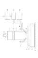
図1において、1はウエハやガラスプレート等である基板、2は基板1を保持する基板チャックである。3は基板ステージで、基板1をX,Y,Zの各方向に平行な軸と各軸まわりの6軸の駆動軸を有する。4はステージ定盤で、基板ステージ3はステージ定盤4にエア浮上あるいは磁気浮上され駆動される。5は投影光学系で6のレチクル(マスク)に描かれた転写パターンを基板1に投影する。なお、投影光学系5の上部にはレチクル6があり、レチクル6は不図示のレチクルステージ上に搭載され、基板ステージ3と同期して露光光に対してスキャン駆動される。また、さらにその上部には照明光学系7が配置され、不図示の光源からの露光光でレチクル6を照明する。9は液浸用液体で、液浸露光装置では基板1と、投影光学系5の最も基板1に近い光学素子(最終レンズ)との間の少なくとも一部に充填されている。なお、露光光がKrFまたはArFエキシマレーザの場合、液体9として空気よりも屈折率の大きい液体、主に水などが用いられる。そして、13は液体9の供給部及び回収部としての液体ノズルで、基板1と投影光学系5の最終レンズの間の少なくとも一部への液体9の供給、および液体9の回収を行うものである。10は純水製造装置であり、11は脱気装置である。12は還元剤導入装置であり、純水製造装置10で製造された水が脱気装置11で脱気され、還元剤導入装置12で還元剤が導入され、液体ノズル13の供給系に接続されている。なお、純水製造装置10、脱気装置11、及び還元剤導入装置12の設置場所は、夫々、露光装置内でも、露光装置外でも構わない。
In FIG. 1,
本実施例では、還元剤導入装置12内で、還元剤としての水素を水素ガスボンベが接続された不図示のガス導入用の膜モジュールを介して液浸用液体としての水の中に導入した。なお、水素は、本実施例のように水素ガスボンベで供給してもよいし、水を電気分解して得られたものを供給しても構わない。更には、電気分解した際にできた水素含有量の高い方の水をそのまま液浸用液体として用いてもよい。還元剤導入装置12では、還元剤が、気体、液体若しくは固体かに応じて、膜モジュールの使用、滴下、攪拌など様々な手法がとられるが、液浸用液体に還元剤が導入されるのであれば、そのいずれの方法を採用しても構わない。
In this example, hydrogen as a reducing agent was introduced into water as an immersion liquid through a gas introducing membrane module (not shown) connected to a hydrogen gas cylinder in the reducing
図1の液浸露光装置の液体9の周りを拡大したものが図2である。 FIG. 2 is an enlarged view of the periphery of the liquid 9 in the immersion exposure apparatus of FIG.
16は投影光学系5の最終レンズである。17は最終レンズのレンズ保持部材である。レンズ保持部材17は高精度に加工されている。さらに、レンズ保持部材17と最終レンズ16との間には、接着剤または、Oリングのようなシール材18が用いられる場合がある。
基板1の外周には、基板1とその表面が同面の液浸用液体9を保持するための液浸液保持板19が設けられる。そして、その中に投影光学系5の焦点位置を検出するために、マーク20及びそのマーク20を介した光の光量を検出するためのセンサー22が設けられる。その際も、接着剤または、Oリングのようなシール材18が用いられる場合がある。
An immersion
シール材18は、接着剤やOリングのように有機物を用いた方が作業性の点で有利である。しかし、前述したように液体9と光8の相互作用により発生した酸化力の強い励起種が存在した場合、シール材18が酸化分解される等して変性し、ヤング率などの物性値がかわったり、パーティクルの原因となったりしていた。本実施例では、液浸用液体に還元剤として水素を混ぜることにより、最終レンズ16と基板1の間に導入される時点では、ORP計(酸化還元電位計)で測定したところ酸化還元電位を−100mVにさげることができた(通常の水の酸化還元電位は+250mV)。酸化力を低減させたため、接着剤やOリングなどの有機物も長期に安定して用いることができた。そのため、作業性よく製造された長期に安定した液浸露光装置を提供することができた。
The sealing
実施例2の液浸露光装置も、図1、図2を用いて説明する。 The immersion exposure apparatus of Example 2 will also be described with reference to FIGS.
図1の液浸露光装置の構成としては、実施例1とほぼ同じであるため、以下には実施例1と異なる部分について主に説明する。なお、実施例1と同様の部材については同じ番号を付している。本実施例では、液浸用液体として水、還元剤としてメタンを用いた。メタンなどの炭化水素化合物は、還元剤として作用した際、CO2を発生させる。そして、そのCO2は水に溶けるので、液浸用液体に導電性をもたせることができ、本出願人が特願2003−422932に記載しているように基板1上に発生する静電気を抑制することが可能となり、静電気によるデバイスの不良の発生を抑えることが可能となる。なお、還元剤として一酸化炭素を用いても同様にCO2を発生させることもできる。
Since the configuration of the immersion exposure apparatus in FIG. 1 is substantially the same as that of the first embodiment, the following description will mainly focus on the differences from the first embodiment. In addition, the same number is attached | subjected about the member similar to Example 1. FIG. In this example, water was used as the immersion liquid and methane was used as the reducing agent. Hydrocarbon compounds such as methane generate CO 2 when acting as a reducing agent. Since the CO 2 is soluble in water, the immersion liquid can be made conductive, and the static electricity generated on the
図2において、レンズ保持部材17は、セラミックスなどを用いることもできるが、金属で構成できれば、加工精度の点で有利であり、SUSなどが用いられる場合がある。また、マーク20も、石英などのガラス材上に金属パターンで形成されている場合が多い。Crなどは、レチクルと同等の加工で作製できるため、よく用いられる。
In FIG. 2, the
しかし、水と光の相互作用により発生した酸化力の強い励起種が存在した場合、保持部材17の材料である金属が酸化されたりなどして、変性し、汚染物質(不純物)として水中に溶け出したり、パーティクルの原因となったりしていた。また、位置合わせマーク20の金属は酸化物に変化し、マークとして必要な光学特性を維持することができなくなったりしていた。本実施例では、液浸水に還元剤としてメタンなどの炭化水素化合物または、一酸化炭素を混ぜることにより、酸化力を低減させ、金属の部材でも長期に安定して用いるものである。そのため、加工精度よく製造された長期に安定した液浸露光装置を提供することができる。
However, when there is an excited species having a strong oxidizing power generated by the interaction between water and light, the metal that is the material of the holding
更に、CO2を同時発生させることにより、純水に導電性をもたせることができ、静電気によるデバイス不良の発生を抑制することもできる。 Further, by simultaneously generating CO 2 , the pure water can be made conductive, and the occurrence of device failure due to static electricity can be suppressed.
実施例3の液浸露光装置を、図3を用いて説明する。 The immersion exposure apparatus of Example 3 will be described with reference to FIG.
液浸露光装置の構成は実施例1とほぼ同じであり、実施例1と同様の部材については同じ番号を付している。 The configuration of the immersion exposure apparatus is almost the same as that of the first embodiment, and the same members as those of the first embodiment are denoted by the same reference numerals.
本実施例では、還元剤導入装置12が、液浸露光装置の制御部15と連動しており、基板1の露光に応じて液体9に還元剤を導入する。ここでは、露光光8が実際に照射される液浸用液体9にのみ、還元剤が導入されるよう制御されている。つまり、基板1上の各露光領域(ショット)を露光光8でスキャンする際に基板1と投影光学系5の間に注入される液浸用液体には還元剤を導入し、各露光領域間をステップ移動する際に基板1と投影光学系5の間に注入される液浸用液体には還元剤を導入しない。これにより、還元剤の使用量を減らすことができ、コストを削減することができる。
In this embodiment, the reducing
実施例4の液浸露光装置を、図4を用いて説明する。 The immersion exposure apparatus of Example 4 will be described with reference to FIG.
液浸露光装置の構成は実施例1とほぼ同じであり、実施例1と同様の部材については同じ番号を付している。 The configuration of the immersion exposure apparatus is almost the same as that of the first embodiment, and the same members as those of the first embodiment are denoted by the same reference numerals.
本実施例では、液体ノズル13で回収された液浸用液体の酸化・還元力を測定器14で測定する。測定手段としては、酸化還元電位を測定してもよいし、その他、酸化・還元力を測定できる装置ならば、何を用いても構わない。測定器14の測定結果が制御部15に送られる。12の還元剤導入装置が、液浸露光装置の制御部15と連動しており、測定値にあわせて、還元剤の量が調整され、液浸用液体に導入されるよう制御されている。これにより、還元剤の使用量を適正なものとすることができ、コストを削減することができる。
In this embodiment, the measuring
次に、上述の液浸露光装置を利用した半導体デバイス(半導体素子)の製造方法の実施例を説明する。 Next, an embodiment of a method for manufacturing a semiconductor device (semiconductor element) using the above-described immersion exposure apparatus will be described.
図5は半導体デバイス(ICやLSI等の半導体チップ、或いは液晶パネルやCCD等)の製造のフローチャートである。本実施例において、ステップ1(回路設計)では、半導体デバイスの回路設計を行う。ステップ2(レチクル製作)では設計した回路パターンを形成したレチクル(マスク)を製作する。一方、ステップ3(ウエハ製造)ではシリコン等の材料を用いてウエハ製造する。ステップ4(ウエハプロセス)は前工程と呼ばれ、前記用意した半導体露光装置によってウエハ上に実際の回路を形成する。 FIG. 5 is a flowchart for manufacturing a semiconductor device (a semiconductor chip such as an IC or LSI, or a liquid crystal panel or CCD). In this embodiment, in step 1 (circuit design), a semiconductor device circuit is designed. In step 2 (reticle fabrication), a reticle (mask) on which the designed circuit pattern is formed is fabricated. On the other hand, in step 3 (wafer manufacture), a wafer is manufactured using a material such as silicon. Step 4 (wafer process) is called a pre-process, and an actual circuit is formed on the wafer by the prepared semiconductor exposure apparatus.
次のステップ5(組立)は後工程と呼ばれ、ステップ4によって製作されたウエハを用いて半導体チップ化する工程であり、アッセンブリ工程(ダイシング、ボンディング)、パッケージング工程(チップ封入)等の工程を含む。 The next step 5 (assembly) is called a post-process, and is a process for forming a semiconductor chip using the wafer manufactured in step 4, and is a process such as an assembly process (dicing, bonding), a packaging process (chip encapsulation), or the like. including.
ステップ6(検査)ではステップ5で製作された半導体デバイスの動作確認テスト、耐久性テスト等の検査を行う。こうした工程を経て半導体デバイスが完成し、これが出荷(ステップ7)される。
In step 6 (inspection), the semiconductor device manufactured in
図6は上記ステップ4のウエハプロセスの詳細なフローチャートである。まず、ステップ11(酸化)ではウエハの表面を酸化させる。ステップ12(CVD)ではウエハ表面に絶縁膜を形成する。 FIG. 6 is a detailed flowchart of the wafer process in Step 4 above. First, in step 11 (oxidation), the wafer surface is oxidized. In step 12 (CVD), an insulating film is formed on the wafer surface.
ステップ13(電極形成)ではウエハ上に電極を蒸着によって形成する。ステップ14(イオン打ち込み)ではウエハにイオンを打ち込む。ステップ15(レジスト処理)ではウエハにレジストを塗布する。 In step 13 (electrode formation), an electrode is formed on the wafer by vapor deposition. In step 14 (ion implantation), ions are implanted into the wafer. In step 15 (resist process), a resist is applied to the wafer.
ステップ16(露光)では前述した液浸露光装置を用いてレチクルの回路パターンをウエハに焼付け露光する。ウエハをローディングしてウエハをレチクルと対向させ、還元剤の導入された液浸用液体を供給回収しながら、露光を行う。露光終了後、ウエハは次のショットへステップ移動し、動作を繰り返す。 In step 16 (exposure), the circuit pattern of the reticle is printed on the wafer by exposure using the above-described immersion exposure apparatus. The wafer is loaded, the wafer is opposed to the reticle, and exposure is performed while supplying and recovering the immersion liquid into which the reducing agent is introduced. After the exposure is completed, the wafer is stepped to the next shot and the operation is repeated.
ステップ17(現像)では露光したウエハを現像する。ステップ18(エッチング)では、現像したレジスト以外の部分を削りとる。これらのステップを繰り返し行うことによってウエハ上に多重に回路パターンが形成される。 In step 17 (development), the exposed wafer is developed. In step 18 (etching), portions other than the developed resist are removed. By repeatedly performing these steps, multiple circuit patterns are formed on the wafer.
尚、本実施例の製造方法を用いれば、従来は製造が難しかった高集積度の半導体デバイスの量産に対応することが出来る。 If the manufacturing method of this embodiment is used, it is possible to cope with mass production of highly integrated semiconductor devices that have been difficult to manufacture.
以上、本発明の好ましい実施例について説明したが、本発明はこれらの実施例に限定されないことはいうまでもなく、その要旨の範囲内で種々の変形及び変更が可能である。 The preferred embodiments of the present invention have been described above, but the present invention is not limited to these embodiments, and various modifications and changes can be made within the scope of the gist.
1 基板
2 基板チャック
3 基板ステージ
4 ステージ定盤
5 投影光学系
6 レチクル
7 照明光学系
8 露光光
9 液体
10 純水製造装置
11 脱気装置
12 還元剤導入装置
13 液体ノズル(供給部、回収部)
14 測定器
15 制御部
16 最終レンズ
17 レンズ保持部材
18 シール材
19 液浸液保持板
20 マーク
22 センサー(CCD等)
DESCRIPTION OF
DESCRIPTION OF
Claims (9)
前記液体に還元剤を導入する装置を有することを特徴とする液浸露光装置。 In an immersion exposure apparatus comprising: a projection optical system that projects a reticle pattern onto a substrate; and a supply unit that supplies liquid to at least a portion between the projection optical system and the substrate.
An immersion exposure apparatus comprising an apparatus for introducing a reducing agent into the liquid.
該露光された基板を現像するステップとを有することを特徴とするデバイス製造方法。 Exposing a substrate using the immersion exposure apparatus according to any one of claims 1 to 6;
And developing the exposed substrate. A device manufacturing method comprising:
前記液体に前記還元剤を導入する装置とを備えることを特徴とする露光システム。 An immersion exposure apparatus comprising: a projection optical system that projects a pattern of a reticle onto a substrate; and a supply unit that supplies liquid to at least a part between the projection optical system and the substrate;
An exposure system comprising: an apparatus for introducing the reducing agent into the liquid.
前記液体に還元剤を導入するステップを有することを特徴とする露光方法。
In an exposure method for exposing a substrate through a projection optical system that projects a pattern of a reticle onto the substrate and a liquid filled in at least a portion between the substrate,
An exposure method comprising a step of introducing a reducing agent into the liquid.
Priority Applications (1)
| Application Number | Priority Date | Filing Date | Title |
|---|---|---|---|
| JP2004307528A JP2006120878A (en) | 2004-10-22 | 2004-10-22 | Liquid-immersion exposure device and device manufacturing method using the same |
Applications Claiming Priority (1)
| Application Number | Priority Date | Filing Date | Title |
|---|---|---|---|
| JP2004307528A JP2006120878A (en) | 2004-10-22 | 2004-10-22 | Liquid-immersion exposure device and device manufacturing method using the same |
Publications (2)
| Publication Number | Publication Date |
|---|---|
| JP2006120878A true JP2006120878A (en) | 2006-05-11 |
| JP2006120878A5 JP2006120878A5 (en) | 2007-12-06 |
Family
ID=36538470
Family Applications (1)
| Application Number | Title | Priority Date | Filing Date |
|---|---|---|---|
| JP2004307528A Withdrawn JP2006120878A (en) | 2004-10-22 | 2004-10-22 | Liquid-immersion exposure device and device manufacturing method using the same |
Country Status (1)
| Country | Link |
|---|---|
| JP (1) | JP2006120878A (en) |
Cited By (2)
| Publication number | Priority date | Publication date | Assignee | Title |
|---|---|---|---|---|
| JP2007013180A (en) * | 2005-06-29 | 2007-01-18 | Qimonda Ag | Fluid for immersion lithography system |
| WO2012011512A1 (en) * | 2010-07-20 | 2012-01-26 | 株式会社ニコン | Exposure method, exposure apparatus and cleaning method |
-
2004
- 2004-10-22 JP JP2004307528A patent/JP2006120878A/en not_active Withdrawn
Cited By (3)
| Publication number | Priority date | Publication date | Assignee | Title |
|---|---|---|---|---|
| JP2007013180A (en) * | 2005-06-29 | 2007-01-18 | Qimonda Ag | Fluid for immersion lithography system |
| JP4504334B2 (en) * | 2005-06-29 | 2010-07-14 | キモンダ アクチエンゲゼルシャフト | Liquid for immersion lithography system |
| WO2012011512A1 (en) * | 2010-07-20 | 2012-01-26 | 株式会社ニコン | Exposure method, exposure apparatus and cleaning method |
Similar Documents
| Publication | Publication Date | Title |
|---|---|---|
| US8570484B2 (en) | Immersion exposure apparatus, device manufacturing method, cleaning method, and cleaning member to remove foreign substance using liquid | |
| JP4752473B2 (en) | Exposure apparatus, exposure method, and device manufacturing method | |
| KR101342303B1 (en) | Exposure device, exposure device member cleaning method, exposure device maintenance method, maintenance device and device manufacturing method | |
| US7528930B2 (en) | Exposure apparatus and device manufacturing method | |
| US8721803B2 (en) | Cleaning liquid, cleaning method, liquid generating apparatus, exposure apparatus, and device fabricating method | |
| US20060192930A1 (en) | Exposure apparatus | |
| JP2006165502A (en) | Exposure apparatus, method of cleaning member thereof, maintenance method of exposure apparatus, maintenance device, and device manufacturing method | |
| KR100870791B1 (en) | Exposure apparatus, exposure method, and exposure system | |
| JP2006245401A (en) | Aligner and device manufacturing method | |
| JP2006120878A (en) | Liquid-immersion exposure device and device manufacturing method using the same | |
| JP2006190971A (en) | Exposure apparatus, exposure method, and device manufacturing method | |
| US8363205B2 (en) | Exposure apparatus | |
| JP2008182167A (en) | Exposure apparatus, exposure method, and exposure system | |
| JP2010010380A (en) | Optical system, aligner, and device manufacturing method | |
| EP3669232A1 (en) | Method for operating an optical apparatus, and optical apparatus | |
| JP2008258324A (en) | Aligner and manufacturing method of device | |
| WO2012011512A1 (en) | Exposure method, exposure apparatus and cleaning method | |
| JP2006073906A (en) | Aligner, exposure system, and device manufacturing method | |
| US6762822B2 (en) | Exposure apparatus and manufacturing method using the same | |
| JP2005142188A (en) | Optical device and semiconductor aligner | |
| JP5018277B2 (en) | Exposure apparatus, device manufacturing method, and cleaning method | |
| JP2007012954A (en) | Exposure device | |
| JP6070784B2 (en) | Liquid supply apparatus, exposure apparatus, liquid supply method, and device manufacturing method | |
| JP2012009668A (en) | Method for manufacturing titanium-containing member, titanium-containing member, exposure device, and method for manufacturing device | |
| JP2010016264A (en) | Exposure device, maintenance method, exposure method, and device manufacturing method |
Legal Events
| Date | Code | Title | Description |
|---|---|---|---|
| A521 | Written amendment |
Free format text: JAPANESE INTERMEDIATE CODE: A523 Effective date: 20071018 |
|
| A621 | Written request for application examination |
Free format text: JAPANESE INTERMEDIATE CODE: A621 Effective date: 20071018 |
|
| RD04 | Notification of resignation of power of attorney |
Free format text: JAPANESE INTERMEDIATE CODE: A7424 Effective date: 20100201 |
|
| A761 | Written withdrawal of application |
Free format text: JAPANESE INTERMEDIATE CODE: A761 Effective date: 20100216 |
|
| A977 | Report on retrieval |
Free format text: JAPANESE INTERMEDIATE CODE: A971007 Effective date: 20100217 |