JP2006078284A - Pulse radar system - Google Patents
Pulse radar system Download PDFInfo
- Publication number
- JP2006078284A JP2006078284A JP2004261479A JP2004261479A JP2006078284A JP 2006078284 A JP2006078284 A JP 2006078284A JP 2004261479 A JP2004261479 A JP 2004261479A JP 2004261479 A JP2004261479 A JP 2004261479A JP 2006078284 A JP2006078284 A JP 2006078284A
- Authority
- JP
- Japan
- Prior art keywords
- signal
- pulse
- reflected signal
- reflected
- received
- Prior art date
- Legal status (The legal status is an assumption and is not a legal conclusion. Google has not performed a legal analysis and makes no representation as to the accuracy of the status listed.)
- Pending
Links
Images


Classifications
-
- B—PERFORMING OPERATIONS; TRANSPORTING
- B09—DISPOSAL OF SOLID WASTE; RECLAMATION OF CONTAMINATED SOIL
- B09B—DISPOSAL OF SOLID WASTE
- B09B3/00—Destroying solid waste or transforming solid waste into something useful or harmless
- B09B3/40—Destroying solid waste or transforming solid waste into something useful or harmless involving thermal treatment, e.g. evaporation
-
- G—PHYSICS
- G01—MEASURING; TESTING
- G01S—RADIO DIRECTION-FINDING; RADIO NAVIGATION; DETERMINING DISTANCE OR VELOCITY BY USE OF RADIO WAVES; LOCATING OR PRESENCE-DETECTING BY USE OF THE REFLECTION OR RERADIATION OF RADIO WAVES; ANALOGOUS ARRANGEMENTS USING OTHER WAVES
- G01S13/00—Systems using the reflection or reradiation of radio waves, e.g. radar systems; Analogous systems using reflection or reradiation of waves whose nature or wavelength is irrelevant or unspecified
- G01S13/02—Systems using reflection of radio waves, e.g. primary radar systems; Analogous systems
- G01S13/06—Systems determining position data of a target
- G01S13/08—Systems for measuring distance only
- G01S13/10—Systems for measuring distance only using transmission of interrupted, pulse modulated waves
- G01S13/20—Systems for measuring distance only using transmission of interrupted, pulse modulated waves whereby multiple time-around echoes are used or eliminated
-
- B—PERFORMING OPERATIONS; TRANSPORTING
- B01—PHYSICAL OR CHEMICAL PROCESSES OR APPARATUS IN GENERAL
- B01F—MIXING, e.g. DISSOLVING, EMULSIFYING OR DISPERSING
- B01F27/00—Mixers with rotary stirring devices in fixed receptacles; Kneaders
- B01F27/05—Stirrers
-
- G—PHYSICS
- G01—MEASURING; TESTING
- G01K—MEASURING TEMPERATURE; MEASURING QUANTITY OF HEAT; THERMALLY-SENSITIVE ELEMENTS NOT OTHERWISE PROVIDED FOR
- G01K7/00—Measuring temperature based on the use of electric or magnetic elements directly sensitive to heat ; Power supply therefor, e.g. using thermoelectric elements
-
- G—PHYSICS
- G01—MEASURING; TESTING
- G01S—RADIO DIRECTION-FINDING; RADIO NAVIGATION; DETERMINING DISTANCE OR VELOCITY BY USE OF RADIO WAVES; LOCATING OR PRESENCE-DETECTING BY USE OF THE REFLECTION OR RERADIATION OF RADIO WAVES; ANALOGOUS ARRANGEMENTS USING OTHER WAVES
- G01S13/00—Systems using the reflection or reradiation of radio waves, e.g. radar systems; Analogous systems using reflection or reradiation of waves whose nature or wavelength is irrelevant or unspecified
- G01S13/02—Systems using reflection of radio waves, e.g. primary radar systems; Analogous systems
- G01S13/06—Systems determining position data of a target
- G01S13/08—Systems for measuring distance only
- G01S13/10—Systems for measuring distance only using transmission of interrupted, pulse modulated waves
- G01S13/18—Systems for measuring distance only using transmission of interrupted, pulse modulated waves wherein range gates are used
-
- G—PHYSICS
- G01—MEASURING; TESTING
- G01S—RADIO DIRECTION-FINDING; RADIO NAVIGATION; DETERMINING DISTANCE OR VELOCITY BY USE OF RADIO WAVES; LOCATING OR PRESENCE-DETECTING BY USE OF THE REFLECTION OR RERADIATION OF RADIO WAVES; ANALOGOUS ARRANGEMENTS USING OTHER WAVES
- G01S13/00—Systems using the reflection or reradiation of radio waves, e.g. radar systems; Analogous systems using reflection or reradiation of waves whose nature or wavelength is irrelevant or unspecified
- G01S13/02—Systems using reflection of radio waves, e.g. primary radar systems; Analogous systems
- G01S13/06—Systems determining position data of a target
- G01S13/08—Systems for measuring distance only
- G01S13/10—Systems for measuring distance only using transmission of interrupted, pulse modulated waves
- G01S13/22—Systems for measuring distance only using transmission of interrupted, pulse modulated waves using irregular pulse repetition frequency
- G01S13/227—Systems for measuring distance only using transmission of interrupted, pulse modulated waves using irregular pulse repetition frequency with repetitive trains of uniform pulse sequences, each sequence having a different pulse repetition frequency
-
- G—PHYSICS
- G01—MEASURING; TESTING
- G01S—RADIO DIRECTION-FINDING; RADIO NAVIGATION; DETERMINING DISTANCE OR VELOCITY BY USE OF RADIO WAVES; LOCATING OR PRESENCE-DETECTING BY USE OF THE REFLECTION OR RERADIATION OF RADIO WAVES; ANALOGOUS ARRANGEMENTS USING OTHER WAVES
- G01S13/00—Systems using the reflection or reradiation of radio waves, e.g. radar systems; Analogous systems using reflection or reradiation of waves whose nature or wavelength is irrelevant or unspecified
- G01S13/02—Systems using reflection of radio waves, e.g. primary radar systems; Analogous systems
- G01S13/06—Systems determining position data of a target
- G01S13/08—Systems for measuring distance only
- G01S13/10—Systems for measuring distance only using transmission of interrupted, pulse modulated waves
- G01S13/24—Systems for measuring distance only using transmission of interrupted, pulse modulated waves using frequency agility of carrier wave
-
- Y—GENERAL TAGGING OF NEW TECHNOLOGICAL DEVELOPMENTS; GENERAL TAGGING OF CROSS-SECTIONAL TECHNOLOGIES SPANNING OVER SEVERAL SECTIONS OF THE IPC; TECHNICAL SUBJECTS COVERED BY FORMER USPC CROSS-REFERENCE ART COLLECTIONS [XRACs] AND DIGESTS
- Y10—TECHNICAL SUBJECTS COVERED BY FORMER USPC
- Y10S—TECHNICAL SUBJECTS COVERED BY FORMER USPC CROSS-REFERENCE ART COLLECTIONS [XRACs] AND DIGESTS
- Y10S435/00—Chemistry: molecular biology and microbiology
- Y10S435/8215—Microorganisms
- Y10S435/822—Microorganisms using bacteria or actinomycetales
- Y10S435/828—Aerobacter
Abstract
Description
本発明は、高周波信号を送信し、その反射波の信号から目標物までの距離を高精度に検知するパルスレーダ装置に関する。 The present invention relates to a pulse radar device that transmits a high-frequency signal and detects the distance from the reflected wave signal to a target with high accuracy.
一般的に、パルスレーダ装置は、所定周波数(例えば、車載レーダの場合76GHz等)に変調されたパルスを送信波として送信し、ターゲット(対象物)による反射波の遅延時間から対象物との距離を測定している。 In general, a pulse radar device transmits a pulse modulated at a predetermined frequency (for example, 76 GHz in the case of an on-vehicle radar) as a transmission wave, and the distance from the delay time of the reflected wave by the target (object) to the object. Is measuring.
図6は、4つのターゲットに対して送信したパルス信号とその反射信号について示しており、説明のための(1)単一送信パルス信号及びその反射信号である(2)受信信号と、(3)繰り返し送信パルス信号及びその反射信号である(4)受信信号と、を示している。 FIG. 6 shows pulse signals transmitted to four targets and their reflection signals. For explanation, (1) a single transmission pulse signal and its reflection signal, (2) a reception signal, and (3 And (4) a reception signal which is a repetitive transmission pulse signal and its reflection signal.
ここで、同図に示す受信信号A1、B1、C1、D1は、パルスレーダ装置の受信部で検出したパルス信号S1に対するターゲット(発信地点からの距離が異なるターゲットA、B、C、D)からの反射信号を受信強度で示し、同様に、受信信号A2、B2、C2、D2は、パルス信号S2に対するターゲットからの反射信号を受信強度で示している。 Here, the received signals A1, B1, C1, and D1 shown in the figure are from the targets (targets A, B, C, and D having different distances from the transmission point) with respect to the pulse signal S1 detected by the receiving unit of the pulse radar device. Similarly, the received signals A2, B2, C2, and D2 indicate the reflected signals from the target with respect to the pulse signal S2 by the received intensity.
同図(1)に示すように、単一送信パルス信号S1をターゲットに対して送信すると、ターゲットからの反射信号を受信し、受信信号A1、B1、C1、D1を検出する。ここで、パルス信号生成時を基準とした受信信号C1及びD1の遅延時間をそれぞれ遅延時間τ1、遅延時間τ2とする。 As shown in FIG. 2A, when a single transmission pulse signal S1 is transmitted to the target, a reflected signal from the target is received and received signals A1, B1, C1, and D1 are detected. Here, it is assumed that the delay times of the reception signals C1 and D1 with respect to the generation time of the pulse signal are the delay time τ1 and the delay time τ2, respectively.
一方、同図(3)に示すように、周期Tの繰り返し送信パルス信号をターゲットに対して送信した場合、受信信号D1の遅延時間τ2は周期Tより大きいために、パルス信号S1に対する受信信号A1〜C1は、同一周期内に検出されるが、受信信号D1は、パルス信号S2に対する受信信号として検出されることとなる(以下、この場合の受信信号D1をゴースト信号という)。 On the other hand, as shown in FIG. 3 (3), when a repetitive transmission pulse signal with a period T is transmitted to the target, the delay time τ2 of the reception signal D1 is larger than the period T, so that the reception signal A1 for the pulse signal S1 .About.C1 are detected within the same period, but the received signal D1 is detected as a received signal with respect to the pulse signal S2 (hereinafter, the received signal D1 in this case is referred to as a ghost signal).
したがって、パルス信号の発生周期をτ、最大検出距離をLとした場合に、パルス信号の発生周期Tは、パルス信号が発信地点からターゲットに反射して戻る時間2L/c(cは光の速度)以上でなければならないという制約があった。これは、パルスの繰り返しによる距離決定の不確定性とわれる。 Therefore, when the generation period of the pulse signal is τ and the maximum detection distance is L, the generation period T of the pulse signal is the time 2 L / c (c is the speed of light) where the pulse signal returns from the transmission point to the target. ) There was a restriction that it must be more than that. This is referred to as uncertainty of distance determination due to repetition of pulses.
非特許文献1には、パルス間隔の繰り返しによる距離決定の不確定性を除去するために、遠いターゲットほど反射強度が小さいという特徴を利用してエコー除去を行なうパルスレーダ装置について開示されている。
Non-Patent
また、特許文献1には、長パルスの繰り返し周期の1周期中に、繰り返し周期の異なる複数の短パルスを混合した混合パルスを送信すると共に、いずれかの送信パルスタイミングを基準として繰り返し周期ごとに異なった時間位置に現れる短パルスからの目標反射受信信号を排除する方法について開示されている。
Further,
特許文献2には、複数の異なる周波数の信号を同時に発生させ、それぞれN個の検出器で位相検波することでパルス繰り返し時間を超える目標距離の対象物を検出する方法について開示されている。
しかし、非特許文献1では、近距離用のパルスレーダ装置において、例えば、自動車と人のようなターゲットの大きさや反射強度が大きく異なる場合、特に近距離での距離計測に高い精度が要求される場合においては、十分な分解能を確保するためにパルスの繰り返し周期を短くする必要があり、反射強度を分離してゴースト信号を除去することが十分にできないという問題があった。
However, in
また、特許文献1では、長パルスと短パルスの複合パルスレーダにおけるパルス間の干渉を除去する方法が開示されているのみであり、パルス繰り返し周期を越えたエコー(ゴースト信号)の除去を目的としたものではない。
特許文献2では、同時に複数の信号を発信するために装置構成が大きくなり、また、位相検出器によって距離を検出することが必要となる。
以上のように、距離範囲が10cm程度〜10数mで高精度の距離計測が可能な極短パルスレーダ装置は、受信信号のS/N(信号対雑音比)を向上させるためにパルス繰り返し周波数を高速にすると、図6で示したように繰り返し周期間に対応する限界検出距離以上の対象物からの反射波(ゴースト信号)の分離が困難であった。さらに、パルス信号を発信する際に自己の発信信号を受信してしまう送受干渉により周期的に反射信号を検出できない場合があった。
In Patent Document 2, the apparatus configuration becomes large in order to simultaneously transmit a plurality of signals, and it is necessary to detect the distance by a phase detector.
As described above, an ultrashort pulse radar device capable of measuring a distance with high accuracy at a distance range of about 10 cm to several tens of meters has a pulse repetition frequency to improve the S / N (signal to noise ratio) of the received signal. As shown in FIG. 6, it is difficult to separate a reflected wave (ghost signal) from an object that is equal to or longer than the limit detection distance corresponding to the repetition period as shown in FIG. Furthermore, when transmitting a pulse signal, the reflected signal may not be detected periodically due to transmission / reception interference that causes the transmission signal to be received.
また、従来の気象用パルスレーダ装置のように長周期パルスを使用するとS/Nを向上させるために送信パルスの尖頭電力が巨大になり回路の実現性、コストが問題となる。
本発明は、上述した問題に鑑みてなされたものであり、その解決しようとする課題は、パルス周期によって決まる計測限界距離以上の距離からの虚像エコー(ゴースト信号)を確実に除去するパルスレーダ装置を提供することである。またパルス繰り返し周期を超えた検出を可能にするパルスレーダ装置を提供することである。
In addition, when a long period pulse is used as in a conventional meteorological pulse radar device, the peak power of the transmission pulse becomes enormous in order to improve the S / N, and the feasibility and cost of the circuit become a problem.
The present invention has been made in view of the above-described problems, and a problem to be solved is a pulse radar device that reliably removes a virtual image echo (ghost signal) from a distance that is equal to or greater than a measurement limit distance determined by a pulse period. Is to provide. Another object of the present invention is to provide a pulse radar device that enables detection exceeding a pulse repetition period.
上記課題を解決するために、本発明に係るパルスレーダ装置は、少なくとも2以上の異なる周期のパルス信号を生成するパルス信号生成手段と、該パルス信号生成手段によって生成したパルス信号を所定の間隔で切換えて出力するパルス信号切替手段と、該パルス信号切替手段からのパルス信号を目標物に対して送信するパルス信号送信手段と、該目標物からの反射信号を受信して、該反射信号の受信強度と該反射信号の受信時間情報とを少なくとも含む受信データを記憶手段に記憶する反射信号受信手段と、該反射信号受信手段によって記憶された受信データから、前記異なる周期のパルス信号に対する反射信号毎の反射信号データを取得する反射信号データ取得手段と、該反射信号データ取得手段によって取得したそれぞれの反射信号データについて、基準となるパルス信号の送信時以後所定の期間における同一遅延時間の反射信号の受信強度を比較し、該受信強度の全てが実質的に0でない場合にのみ前記反射信号を前記基準となるパルス信号に対する反射信号と特定する反射信号特定手段と、を備える。 In order to solve the above-described problem, a pulse radar device according to the present invention includes a pulse signal generation unit that generates pulse signals having at least two different periods, and a pulse signal generated by the pulse signal generation unit at a predetermined interval. A pulse signal switching means for switching and outputting; a pulse signal transmitting means for transmitting a pulse signal from the pulse signal switching means to a target; and receiving a reflected signal from the target; Reflected signal receiving means for storing received data including at least the intensity and reception time information of the reflected signal in the storing means, and for each reflected signal for the pulse signal having the different period from the received data stored by the reflected signal receiving means. Reflection signal data acquisition means for acquiring the reflection signal data of the respective reflection signal data obtained by the reflection signal data acquisition means. The received signal strengths of the reflected signals having the same delay time in a predetermined period after the transmission of the reference pulse signal are compared, and the reflected signal is used as the reference only when all of the received signals are not substantially zero. And a reflection signal specifying means for specifying the reflection signal for the pulse signal.
本発明によると、パルス信号生成手段によって生成した異なる周期のパルス信号を、パルス信号切替手段によって所定の間隔で切換えて目標物に送信し、その反射波を反射信号受信手段によって受信データとして記憶手段に記憶する。 According to the present invention, pulse signals having different periods generated by the pulse signal generating means are switched at predetermined intervals by the pulse signal switching means and transmitted to the target, and the reflected wave is stored as received data by the reflected signal receiving means. To remember.
そして、反射信号データ取得手段によって、受信データから前記異なるパルス信号に対応する反射信号毎の反射信号データを取得し、基準となるパルス信号に対する同一遅延時間における反射信号データを比較し、反射信号データの全てに実質的に0でない受信強度が存在した場合に、前記基準となるパルス信号に対する反射信号と特定する。 Then, the reflected signal data acquisition means acquires the reflected signal data for each reflected signal corresponding to the different pulse signal from the received data, compares the reflected signal data at the same delay time with respect to the reference pulse signal, and reflects the reflected signal data. When there is a reception intensity that is substantially non-zero in all of the above, it is specified as a reflected signal with respect to the reference pulse signal.
これにより、例えば、前記比較に使用した反射信号データのいずれか1つにしか受信強度が存在しない場合などは、当該受信強度を前記基準となるパルス信号に対する反射信号と特定しないので、前記基準となるパルス信号の前に目標物に送信されたパルス信号の反射信号(ゴースト信号)を確実に排除することが可能となる。 Thereby, for example, when the reception intensity exists only in one of the reflected signal data used for the comparison, the reception intensity is not specified as a reflection signal for the reference pulse signal, and thus the reference and It is possible to reliably eliminate the reflection signal (ghost signal) of the pulse signal transmitted to the target before the pulse signal.
また、前記反射信号受信手段において、所望の時間でのみ前記目標物からの反射信号を受信して、該所望の時間における反射信号の受信強度を少なくとも含む受信データを記憶手段に記憶し、前記反射信号特定手段は、前記反射信号データ取得手段によって取得したそれぞれの反射信号データについて、前記所望の時間における反射信号の受信強度を比較し、該受信強度の全てが実質的に0でない場合にのみ前記反射信号を前記基準となるパルス信号に対する反射信号と特定してもよい。 The reflected signal receiving means receives a reflected signal from the target only at a desired time, stores reception data including at least the received intensity of the reflected signal at the desired time in the storage means, and The signal specifying means compares the reflected signal reception intensity at the desired time with respect to each reflected signal data acquired by the reflected signal data acquiring means, and only when the received intensity is not substantially zero, The reflected signal may be specified as a reflected signal with respect to the reference pulse signal.
これにより、所望の時間(基準となるパルス信号からの所望の遅延時間)における前記目標物からの反射信号を受信して、前記反射信号特定手段により反射信号の特定を行なうので、所望の時間において、基準となるパルス信号からの反射信号の存在を素早く特定することが可能となる。 Thus, the reflected signal from the target is received at a desired time (desired delay time from the reference pulse signal), and the reflected signal is specified by the reflected signal specifying means. It is possible to quickly identify the presence of a reflected signal from a reference pulse signal.
また、所望の時間を順次ずらして(スライド)していくことによって、所望の範囲の遅延時間における基準となるパルス信号からの反射信号の存在を素早く特定することが可能となる。すなわち、所望の範囲の距離にある対象物を素早く特定することが可能となる。 Further, by sequentially shifting (sliding) a desired time, it is possible to quickly specify the presence of a reflected signal from a reference pulse signal in a delay time within a desired range. That is, it is possible to quickly identify an object within a desired range of distance.
また、前記反射信号受信手段は、前記目標物からの反射信号の信号強度と、該反射信号の遅延時間のみを前記記憶手段に記憶してもよい。
これにより、記憶手段(例えば、RAMやEEPROMなど)の容量を小さくすることが可能となる。
The reflected signal receiving means may store only the signal intensity of the reflected signal from the target and the delay time of the reflected signal in the storage means.
This makes it possible to reduce the capacity of the storage means (for example, RAM, EEPROM, etc.).
さらに、前記パルス信号生成手段は、3つの異なる周期Ta、Tb及びTcのパルス信号を生成し、該3つのパルス信号の周波数fa、fb及びfcは、周波数fで検出可能な限界距離の倍数mを用いて、fb=fa*(m+N1)/m、fc=fa*m/(m+N2)、N1<m、N2<m、の関係式で算出される周波数又は算出された周波数に近い値の組み合わせの周波数を使用してもよい。 これにより、送信したパルス信号が限界距離のm倍の距離までの目標物から反射して受信されるまでの間に、異なる周期Ta、Tb及びTcのパルス信号が同じ遅延時間に受信されることを防止することが可能となる。 Further, the pulse signal generating means generates pulse signals having three different periods Ta, Tb, and Tc, and the frequencies fa, fb, and fc of the three pulse signals are multiples of a limit distance m that can be detected at the frequency f. , Fb = fa * (m + N1) / m, fc = fa * m / (m + N2), N1 <m, N2 <m, a frequency calculated by a relational expression or a combination of values close to the calculated frequency May be used. As a result, pulse signals having different periods Ta, Tb, and Tc are received at the same delay time until the transmitted pulse signal is reflected and received from the target up to a distance m times the critical distance. Can be prevented.
さらに、前記反射信号特定手段は、前記受信強度の最小値が実質的に0でない場合にのみ前記反射信号を前記基準となるパルス信号に対する反射信号と特定してもよい。
これにより、一の反射信号データが送受干渉によって大きな受信強度を記録していても、他の反射信号データの受信強度と比較して最小値をとることによって、反射信号のみの受信強度を特定することができるので、送受干渉の影響を受けることなく反射信号特定手段によって反射信号を特定することが可能となる。また、限界処理のm倍の距離までの目標物から反射して受信される信号の遅延時間が一致しないことから限界処理のm倍の距離まで検出距離を延ばすことができる。
Further, the reflected signal specifying means may specify the reflected signal as a reflected signal for the reference pulse signal only when the minimum value of the received intensity is not substantially zero.
As a result, even if one reflected signal data records a large received intensity due to transmission / reception interference, the received intensity of only the reflected signal is specified by taking the minimum value compared with the received intensity of the other reflected signal data. Therefore, the reflected signal can be specified by the reflected signal specifying means without being affected by the transmission / reception interference. Further, since the delay times of the signals reflected and received from the target up to m times the limit processing do not match, the detection distance can be extended up to m times the limit processing.
以上のように、本発明によると、パルス周期によって決まる計測限界距離以上の距離からの虚像エコー(ゴースト信号)を確実に除去するパルスレーダ装置を提供することが可能となる。またパルス繰り返し周期を超えた検出を可能にするパルスレーダ装置を提供することも可能となる。 As described above, according to the present invention, it is possible to provide a pulse radar device that reliably removes a virtual image echo (ghost signal) from a distance greater than or equal to a measurement limit distance determined by a pulse period. It is also possible to provide a pulse radar device that enables detection exceeding the pulse repetition period.
以下、本発明の実施形態について図1から図5に基づいて説明する。
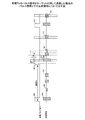
図1は、本発明の実施例に係るパルスレーダ装置の構成を示すブロック図である。
同図に示すパルスレーダ装置では、送信部にfmOSC11、送信高周波発振器(VCO)12、ASKスイッチ回路13、高速矩形波OSC14及び送信アンテナ(T−ant)15を有し、また受信部にはローパスフィルタ(LPF)16、受信アンテナ(R−ant)17、第1のゲート(高周波ゲート、Gate1)18、受信ミキサ(Mix)19、第2のゲート(IF帯ゲート、Gate2)21、第1のデジタルシグナルプロセッサ(DSP1)24、バンドパスフィルタ(BPF)22、I/Q検波器(I/Q−DET)23及び第2のデジタルシグナルプロセッサ(DSP2)20を有し、さらに、高速矩形波OSC14は、矩形波(繰り返しパルス信号)を生成する周期の異なる3つのOSC9a〜9c、及びOSC切替器10を有している。
Hereinafter, embodiments of the present invention will be described with reference to FIGS. 1 to 5.
FIG. 1 is a block diagram showing a configuration of a pulse radar apparatus according to an embodiment of the present invention.
The pulse radar apparatus shown in the figure has a
fmOSC11は、送信高周波発振器12に対して周波数fmの三角波信号を出力する。送信高周波発振器12は、電圧制御発振器で、fmOSC11から入力される直流電圧値に基づいて周波数変調を行い、入力電圧に比例した周波数を持つ周波数変調された高周波FM波を搬送波としてASKスイッチ回路13に出力する。ASKスイッチ回路13は、送信高周波発振器12から入力される搬送波を、高速矩形波OSC14からの矩形波によってスイッチングして、ASK(Amplitude Shift Keying)方式の変調を行なう。
The
OSC9a〜9cは、それぞれ異なる周期Ta、Tb及びTc(それぞれ周波数fa、fb及びfc)の矩形波を生成する高周波数発振器である。これらOSC9a〜9cの出力は、OSC切替器10によって周期T0(周波数をf0とする)で切換えられる。本実施例においては、OSC切替器10による切替周期T0は10msとなる。したがって、10ms毎にOSC9a、OSC9b、OSC9cの順に順次切換えて高速矩形波OSC14から出力されることとなる。
The
ただし、周期T0(周波数f0)はこれに限定するものではなく、少なくともTa+Tb+Tc以上の周期を持つ周波数から、第1のデジタルシグナルプロセッサ24等の演算能力等を考慮し、必要に応じて任意の周期を決定すればよい。
However, the period T0 (frequency f0) is not limited to this, and an arbitrary period is selected as necessary from the frequency having a period of at least Ta + Tb + Tc in consideration of the computing ability of the first
本実施例においては、周波数fa(周期Ta)で検出可能な限界距離の倍数をmとした場合に、下記の式(1)〜(4)から算出される周波数、又はその周波数に近い値の組み合わせから適宜選択して周期Ta、Tb及びTcを決めている。 In the present embodiment, when the multiple of the limit distance detectable at the frequency fa (cycle Ta) is m, the frequency calculated from the following formulas (1) to (4) or a value close to the frequency is obtained. The periods Ta, Tb and Tc are determined by appropriately selecting from the combinations.
fb ≒ fa*(m+N1)/m ・・・ (1)
fc ≒ fa*m/(m+N2) ・・・ (2)
0< N1 < m ・・・ (3)
0< N2 < m ・・・ (4)
例えば、周波数faが10MHzでの検出可能な限界距離が15mであった場合に、45mまで検出距離を確保したい場合には、mは3(=検出距離/検出可能な限界距離=45/15)となり、式(3)及び式(4)からN1及びN2は、1又は2となる。
fb ≒ fa * (m + N1) / m (1)
fc≈fa * m / (m + N2) (2)
0 <N1 <m (3)
0 <N2 <m (4)
For example, if the limit distance that can be detected at a frequency fa of 10 MHz is 15 m, m is 3 (= detection distance / detectable limit distance = 45/15) when it is desired to secure the detection distance to 45 m. Thus, N1 and N2 are 1 or 2 from the equations (3) and (4).
したがって、この場合の周波数fa、fb及びfcの組み合わせは式(1)及び(2)から下記の4通りとなる。
(fa、fb、fc)=(10、10*4/3、10*3/4)・・・(5)
(fa、fb、fc)=(10、10*4/3、10*3/5)・・・(6)
(fa、fb、fc)=(10、10*5/3、10*3/4)・・・(7)
(fa、fb、fc)=(10、10*5/3、10*3/5)・・・(8)
以上の式(5)〜(8)から任意の組み合わせを選択して使用すればよい。例えば、式(6)から(Ta、Tb、Tc)は(100ns、80ns、170ns)となる。なお、式(1)及び(2)の計算に際しては、割り切れない場合もあるので、算出結果の近傍で都合の良い値を使用すればよい。例えば、端数や小数点以下の値は切り捨てもよいし、発振器の精度の制約等を考慮して算出結果に最も近い25の倍数の値を使用してもよい。
Therefore, the combinations of the frequencies fa, fb, and fc in this case are the following four from Equations (1) and (2).
(Fa, fb, fc) = (10, 10 * 4/3, 10 * 3/4) (5)
(Fa, fb, fc) = (10, 10 * 4/3, 10 * 3/5) (6)
(Fa, fb, fc) = (10, 10 * 5/3, 10 * 3/4) (7)
(Fa, fb, fc) = (10, 10 * 5/3, 10 * 3/5) (8)
Any combination may be selected from the above formulas (5) to (8). For example, from the formula (6), (Ta, Tb, Tc) becomes (100 ns, 80 ns, 170 ns). It should be noted that in the calculation of equations (1) and (2), there are cases where the calculation is not divisible, so a convenient value may be used in the vicinity of the calculation result. For example, a fraction or a value after the decimal point may be rounded down, or a value that is a multiple of 25 closest to the calculation result may be used in consideration of restrictions on the accuracy of the oscillator.
以上のように、周期Ta、Tb及びTcを決定することによって、少なくとも45mにある対象物からの反射波を受信するまでの間は、周波数の繰り返し位置が重ならないようにすることができる。 As described above, by determining the periods Ta, Tb, and Tc, it is possible to prevent frequency repetition positions from overlapping until a reflected wave from an object at least 45 m is received.
高速矩形波OSC14は、OSC切替器10によって切替えられた(選択された)OSCからの矩形波をASKスイッチ回路13、第2のデジタルシグナルプロセッサ20、及びI/Q検波器23に分配する。また、送信アンテナ15は、ASKスイッチ回路13から出力される送信信号を外部に放射する。
The high-speed
ローパスフィルタ16は、高速矩形波OSC14の出力信号から周波数fa、fb又はfcの基本波成分のみを抽出し、I/Q検波器23に出力する。受信アンテナ17は、送信アンテナ15から放射された送信信号が対象物に反射された反射波信号を受信し、受信信号として第1のゲート18に入力する。
The low-
第1のゲート18及び第2のゲート21は、高速動作するANDゲートで、第2のデジタルシグナルプロセッサ20からのゲーティング信号に基づいて入力信号をゲーティングし、出力する。
The
受信ミキサ19は、送信高周波発振器12からのFM波によって第1のゲート18からの高周波信号を周波数変換する。第2のデジタルシグナルプロセッサ20は、第1のデジタルシグナルプロセッサ24からの遅延指令信号に基づいて高速矩形波OSC14からのパルス信号を遅延させてゲーティング信号を生成し、第1のゲート18及び第2のゲート21に出力する。
The
バンドパスフィルタ22は、第2のゲート21の出力信号から周波数fa、fb又はfc付近の成分を抽出しI/Q検波器23に出力する。I/Q検波器23は、ローパスフィルタ16の出力信号を基準位相として、バンドパスフィルタ22からの入力信号の位相検波を行い、同相成分(Ich)及び直交成分(Qch)をそれぞれ第1のデジタルシグナルプロセッサ24に出力する。
The
第1のデジタルシグナルプロセッサ24は、第2のデジタルシグナルプロセッサ20に遅延指令信号によってゲーティング信号の遅延時間を指示し、I/Q検波器23の出力を測定してレベルが最大になる時の受信信号の遅延時間τとして求め、この受信信号(反射信号)と遅延時間τとを揮発性メモリであるRAM(Random Access Memory)25に記憶する。
The first
この時、RAM25に記憶される受信データは、周期Ta、Tb及びTcの順に周期T0で切り替わる送信信号(パルス信号)と、その送信信号(パルス信号)に対する反射信号(I/Q検波器23から送られたI、Q成分)と、反射信号の受信強度情報と、反射信号を受信した時間情報とが含まれるデータである。
At this time, the reception data stored in the
第1のデジタルシグナルプロセッサ24は、この受信データからそれぞれ周期Ta、周期Tb、周期Tcのみの送信信号と、その送信信号に対する反射信号(I/Q検波器23から送られたI、Q成分)と、反射信号の受信強度情報と、反射信号を受信した時間情報とが含まれるデータを抽出して、第1の反射信号データ、第2の反射信号データ及び第3の反射信号データを生成する。
The first
そして、第1から第3の反射信号を比較することによって反射信号を特定し、特定した反射信号の遅延時間τから目標物との距離Rを算出して出力する。
例えば、I/Q検波器(I/Q−DET)23からの出力であるI、Q成分、高速矩形波OSC14の出力に対すると同一の送信パルスの繰り返し周期T(Tは、Ta、Tb又はTc)、および光の速度cを用いて、位相差θ、遅延時間τ、およびターゲットまでの距離Rは次式によって求めることができる。
Then, the reflected signal is identified by comparing the first to third reflected signals, and the distance R to the target is calculated from the delay time τ of the identified reflected signal and output.
For example, the repetition period T (T is Ta, Tb or Tc) of the same transmission pulse as the output from the I / Q detector (I / Q-DET) 23, the I and Q components, and the output of the high-speed rectangular wave OSC14. ) And the speed of light c, the phase difference θ, the delay time τ, and the distance R to the target can be obtained by the following equations.
θ=tan-1(Q/I) ・・・ ( 9)
τ=θ*T/2π ・・・ (10)
R=τ×c/2=θ*T*c/4π ・・・ (11)
以上に説明したように、パルス信号生成手段はOSC9a〜9cによって実現され、パルス信号切替手段はOSC切替器10と第1のデジタルシグナルプロセッサ24とによって実現され、パルス信号送信手段は、fmOSC11と送信高周波発振器12とASKスイッチ回路13と高速矩形波OSC14と送信アンテナ15とによって実現される。
θ = tan −1 (Q / I) (9)
τ = θ * T / 2π (10)
R = τ × c / 2 = θ * T * c / 4π (11)
As described above, the pulse signal generation means is realized by the
また、反射信号受信手段はローパスフィルタ16と受信アンテナ17と第1のゲート18と受信ミキサ19と第2のデジタルシグナルプロセッサ20と第2のゲート21とバンドパスフィルタ22とI/Q検波器23と第1のデジタルシグナルプロセッサ24とRAM25とによって実現され、受信データはRAM25に格納される。
The reflected signal receiving means includes a low-
さらに、反射信号データ取得手段、反射信号特定手段及び距離算出手段は第1のデジタルシグナルプロセッサ24とRAM25とによって実現され、反射信号データ取得手段は、受信データから第1の反射信号データと第2の反射信号データと第3の反射信号データとを生成しRAM25に格納し、反射信号特定手段は、第1から第3の反射信号データを比較することによって反射信号を特定し、距離算出手段は、特定した反射信号の遅延時間から式(9)〜(11)を用いてターゲットまでの距離を算出する。 図2A〜図2Dは、本発明の実施例に係るパルスレーダ装置おいて、4つのターゲットに対して送信したパルス信号の反射信号と検出信号との関係についての例を示す図である。
Further, the reflected signal data acquiring means, the reflected signal specifying means, and the distance calculating means are realized by the first
図2Aは、OSC9aで生成された周期Taのパルス信号をターゲットに対して送信した場合のパルス信号とその反射信号について示し、第1の反射信号データに対応する。図2Bは、OSC9bで生成された周期Tbのパルス信号をターゲットに対して送信した場合のパルス信号とその反射信号について示し、第2の反射信号データに対応する。図2Cは、OSC9cで生成された周期Tcのパルス信号をターゲットに対して送信した場合のパルス信号とその反射信号について示し、第3の反射信号データに対応する。また、図2Dは、図2A〜図2Cまでの反射信号を比較するために基準(検出基準)とする任意の基準パルス信号とその基準パルス信号以後における反射信号の比較により検出した検出信号とを示している。
FIG. 2A shows a pulse signal and its reflection signal when a pulse signal having a period Ta generated by the
図2Aに示すSa0〜Sa2は、ターゲットに対して送信されたOSC9aで生成された周期Taのパルス信号である。また、反射信号Aa0、Ba0、Ca0、Da0は、それぞれ距離の異なる4つのターゲットからのパルス信号Sa0に対する反射信号の受信強度を示している。同様に、反射信号Aa1、Ba1、Ca1、Da1は、上記ターゲットからのパルス信号Sa1に対する反射信号の受信強度を示している。
Sa0 to Sa2 shown in FIG. 2A are pulse signals with a period Ta generated by the
反射信号Da0は、周期Taで検出可能な限界距離以上の距離であるためにパルス信号Sa0送信から1周期以内に検出ができていないことがわかる。したがって、このままでは、次のパルス信号Sa1に対する反射信号(例えば、Aa1、Ba1、Ca1)と区別(分離)することができない。この場合の反射信号Da0を以下ではパルス信号Sa1に対するゴースト信号Da0という。 It can be seen that the reflected signal Da0 is not detected within one cycle from the transmission of the pulse signal Sa0 because the reflected signal Da0 is a distance greater than the limit distance detectable in the cycle Ta. Therefore, it cannot be distinguished (separated) from the reflected signal (for example, Aa1, Ba1, Ca1) for the next pulse signal Sa1 as it is. The reflected signal Da0 in this case is hereinafter referred to as a ghost signal Da0 for the pulse signal Sa1.
図2Bに示すSb0〜Sb2は、ターゲットに対して送信されたOSC9bで生成された周期Tbのパルス信号である。また、反射信号Ab0、Bb0、Cb0、Db0は、図2Aと同じターゲットからのパルス信号Sb0に対する反射信号の受信強度を示している。反射信号Ab1、Bb1、Cb1、Db1は、上記ターゲットからのパルス信号Sb1に対する反射信号の受信強度を示している。
Sb0 to Sb2 shown in FIG. 2B are pulse signals with a period Tb generated by the
反射信号Db0は、周期Tbで検出可能な限界距離以上の距離であるためにパルス信号Sb1に対するゴースト信号Db0となっており、パルス信号Sb1に対する反射信号と区別することができない。 The reflected signal Db0 is a ghost signal Db0 for the pulse signal Sb1 because it is a distance that is not less than a limit distance that can be detected in the period Tb, and cannot be distinguished from the reflected signal for the pulse signal Sb1.
図2Cに示すSc0〜Sc2は、ターゲットに対して送信されたOSC9cで生成された周期Tcのパルス信号である。また、反射信号Ac0、Bc0、Cc0、Dc0は、図2Aと同じターゲットからのパルス信号Sc0に対する反射信号の受信強度を示している。反射信号Ac1、Bc1、Cc1、Dc1は、上記ターゲットからのパルス信号Sc1に対する反射信号の受信強度を示している。 Sc0 to Sc2 shown in FIG. 2C are pulse signals with a cycle Tc generated by the OSC 9c transmitted to the target. Reflected signals Ac0, Bc0, Cc0, and Dc0 indicate the received signal reception intensity with respect to the pulse signal Sc0 from the same target as in FIG. 2A. The reflection signals Ac1, Bc1, Cc1, and Dc1 indicate the reception strength of the reflection signal with respect to the pulse signal Sc1 from the target.
反射信号Dc0は、周期Tcで検出可能な限界距離以上の距離であるためにパルス信号Sc1に対するゴースト信号Dc0となっており、パルス信号Sc1に対する反射信号と区別することができない。 The reflected signal Dc0 is a ghost signal Dc0 for the pulse signal Sc1 because it is a distance that is not less than a limit distance detectable in the cycle Tc, and cannot be distinguished from the reflected signal for the pulse signal Sc1.
図2Dに示すパルス信号Sdは、任意のパルスタイミング基準を示す。パルスタイミング基準とは、図2A〜図2Cに示した反射信号を比較するための基準である。本実施例では、図2Aのパルス信号Sa1、図2Bのパルス信号Sb1、図2Cのパルス信号Sc1をパルスタイミング基準とし、反射信号について比較を行なっている。 The pulse signal Sd shown in FIG. 2D represents an arbitrary pulse timing reference. The pulse timing reference is a reference for comparing the reflected signals shown in FIGS. 2A to 2C. In this embodiment, the pulse signal Sa1 in FIG. 2A, the pulse signal Sb1 in FIG. 2B, and the pulse signal Sc1 in FIG.
ただし、パルスタイミング基準は任意である。すなわち、本実施例ではパルス信号Sa1、Sb1及びSc1をパルスタイミング基準としたが、例えば、パルス信号Sa0、Sb0及びSc0をパルスタイミング基準としてもよく、パルス信号Sa0、Sb1、Sc0をパルスタイミング基準としてもよい。 However, the pulse timing reference is arbitrary. That is, in this embodiment, the pulse signals Sa1, Sb1, and Sc1 are used as the pulse timing reference. However, for example, the pulse signals Sa0, Sb0, and Sc0 may be used as the pulse timing reference, and the pulse signals Sa0, Sb1, and Sc0 are used as the pulse timing reference. Also good.
同図に示す検出信号は、図2Aのパルスタイミング基準(パルス信号Sa1送信時)以後に検出した反射信号と、図2Bのパルスタイミング基準(パルス信号Sb1送信時)以後に検出した反射信号と、図2Cのパルスタイミング基準(パルス信号Sc1送信時)以後に検出した反射信号とを比較し、その受信強度の最小値を持つ信号をパルスタイミング基準におけるパルス信号Sdに対する反射信号としたものである。 The detection signal shown in the figure includes a reflection signal detected after the pulse timing reference (when transmitting the pulse signal Sa1) in FIG. 2A, a reflection signal detected after the pulse timing reference (when transmitting the pulse signal Sb1) in FIG. The reflected signal detected after the pulse timing reference (when transmitting the pulse signal Sc1) in FIG. 2C is compared, and the signal having the minimum value of the received intensity is used as the reflected signal for the pulse signal Sd in the pulse timing reference.
例えば、パルスタイミング基準からの遅延時間がt0では、反射信号Aa1(図2A)、反射信号Ab1(図2B)、反射信号Ac1(図2C)の受信強度が検出されているので、これらの受信強度を比較して最小となる反射信号を検出信号Adとしている。 For example, when the delay time from the pulse timing reference is t0, the received intensities of the reflected signal Aa1 (FIG. 2A), the reflected signal Ab1 (FIG. 2B), and the reflected signal Ac1 (FIG. 2C) are detected. The reflected signal that becomes the minimum by comparing the two is used as the detection signal Ad.
また、パルスタイミング基準からの遅延時間がt1の時を見ると、図2Bに示す第2の反射信号データには、ゴースト信号Db0についての受信強度が検出されているが、図2Aに示す第1の反射信号データ及び図2Cに示す第3の反射信号データには受信強度が検出されていない(受信強度が実質的に0となっている)。したがって、これらの受信強度を比較して最小値をとると受信強度は0となる(ゴースト信号Db0は検出しない)。 When the delay time from the pulse timing reference is t1, the reception intensity for the ghost signal Db0 is detected in the second reflected signal data shown in FIG. 2B, but the first reflection shown in FIG. The received signal strength is not detected in the reflected signal data and the third reflected signal data shown in FIG. 2C (the received signal strength is substantially 0). Therefore, when these received intensities are compared and the minimum value is taken, the received intensity becomes 0 (ghost signal Db0 is not detected).
ここで、受信強度が実質的に0とは、反射信号以外のノイズが受信されることによって受信強度が0とならない場合であっても0とみなすことをいう。したがって、パルスレーダ装置の反射信号受信手段の精度に応じて適宜、実質的に0と判断する範囲を決め、この範囲の受信強度の場合には、受信強度が0(反射信号を受信しない)と判断すればよい。 Here, the fact that the reception intensity is substantially 0 means that even if the reception intensity does not become 0 due to reception of noise other than the reflected signal, it is regarded as 0. Accordingly, a range determined to be substantially 0 is appropriately determined according to the accuracy of the reflected signal receiving means of the pulse radar apparatus. If the received intensity is within this range, the received intensity is 0 (no reflected signal is received). Just judge.
以上に説明したように、異なる周期のパルス信号の反射信号(受信強度)を比較することによって、基準となるパルス信号(パルスタイミング基準)に対する反射信号を容易に特定し、さらに、ゴースト信号を確実に排除することが可能となる。 As described above, by comparing the reflected signals (reception strength) of pulse signals with different periods, the reflected signal with respect to the reference pulse signal (pulse timing reference) can be easily identified, and the ghost signal can be reliably detected. Can be eliminated.
また、パルス信号送信手段によってパルス信号を送信する際、反射信号受信手段における第1のゲート18を閉じて、自己の発するパルス信号を直接受信しないようにしているが、パルスレーダ装置内部を伝搬するなどして自己の発するパルス信号を直接受信してしまう場合がある(送受干渉)。
Further, when transmitting the pulse signal by the pulse signal transmitting means, the
したがって、この送受干渉が発生するタイミングで反射信号を受信しても、本当に反射信号を受信したのか送受干渉によるものなのか(反射信号は受信していないのか)を特定することが困難であったが、異なる周期のパルス信号の反射信号(受信強度)を比較することによって、送受干渉がある場合であっても確実に反射信号の有無又は受信強度を認識することが可能となる。 Therefore, even if the reflected signal is received at the timing when this transmission / reception interference occurs, it is difficult to specify whether the reflected signal is actually received or due to the transmission / reception interference (whether the reflected signal is not received). However, by comparing the reflection signals (reception strength) of the pulse signals having different periods, it is possible to reliably recognize the presence or absence of the reflection signal or the reception strength even when there is transmission / reception interference.
また、パルスタイミング基準におけるパルス信号に対する反射信号を受信するまでの遅延時間(図2Dに示す遅延時間t3)が、繰り返し周期(例えば、Ta、Tb又はTc)を越えた場合であっても確実に検出することができる(例えば、図2Dに示す検出信号Dd)。 In addition, even when the delay time (delay time t3 shown in FIG. 2D) until receiving the reflected signal with respect to the pulse signal based on the pulse timing reference exceeds the repetition period (for example, Ta, Tb, or Tc), it is ensured. It can be detected (for example, the detection signal Dd shown in FIG. 2D).
図3は、反射信号特定処理の詳細を示すフローチャートである。
図1に示したパルスレーダ装置の動作を開始すると、ステップS301において、第1のデジタルシグナルプロセッサ24が、OSC切替器10に対してOSC9aを選択するように指示を出し、パルス信号送信手段によりターゲットに対して周期Taのパルス信号(高速矩形波)がASK変調されて送信される。
FIG. 3 is a flowchart showing details of the reflected signal specifying process.
When the operation of the pulse radar apparatus shown in FIG. 1 is started, in step S301, the first
そして、反射信号受信手段により、反射信号の受信強度を(検出する時間おくれ(遅延時間)をスライディングしながら)測定し、受信データをRAM25に記憶する。本実施例においては、20kHzでOSC切替器10の切替えを行なうので、50μs間受信強度を測定すると、ステップS302に処理を移行する。
Then, the reception intensity of the reflected signal is measured by the reflected signal receiving means (while sliding the detection time interval (delay time)), and the received data is stored in the
処理をステップS302に移行すると、第1のデジタルシグナルプロセッサ24は、OSC切替器10に対してOSC9bを選択するように指示を出し、パルス信号送信手段によりターゲットに対して周期Tbのパルス信号(高速矩形波)をASK変調して送信し、反射信号受信手段により、反射信号の受信強度を(検出する時間おくれをスライディングしながら)測定して受信データをRAM25に記憶する。そして、50μs間受信強度を測定すると、ステップS303に処理を移行する。
When the process proceeds to step S302, the first
ステップS303も、ステップS301及びステップS302と同様に、第1のデジタルシグナルプロセッサ24が、OSC切替器10に対してOSC9cを選択するように指示を出し、パルス信号送信手段によりターゲットに対して周期Tcのパルス信号(高速矩形波)をASK変調して送信し、50μsの間、反射信号受信手段により、反射信号の受信強度を(検出する時間おくれをスライディングしながら)測定して受信データをRAM25に記憶する。
Similarly to steps S301 and S302, in step S303, the first
ここで、反射信号の受信強度を検出する時間おくれをスライディングしながら測定するとは、第1のゲートを開閉することにより所定の時間から離散的又は連続的に反射信号の受信強度を検出することである。 Here, sliding while measuring the time interval for detecting the reception strength of the reflected signal is to detect the reception strength of the reflected signal discretely or continuously from a predetermined time by opening and closing the first gate. is there.
ステップS301からステップS303の処理によって、各周期Ta、Tb及びTcのパルス信号に対する反射信号の受信強度の測定が完了すると、ステップS304に処理を移行する。 When the measurement of the reception intensity of the reflected signal with respect to the pulse signals having the respective periods Ta, Tb, and Tc is completed by the processes from step S301 to step S303, the process proceeds to step S304.
ステップS304では、第1のデジタルシグナルプロセッサ24が、RAM25に記憶されている受信データを読出して、第1の反射信号データ(図2A参照)、第2の反射信号データ(図2B参照)及び第3の反射信号データ(図2C参照)を生成する。
In step S304, the first
そして、各反射信号データについてパルスタイミング基準を決定し、各反射信号データのパルスタイミング基準からの遅延時間t(初期値は0s)における一定区間(以下、刻み時間という)の受信強度を比較して最小の受信強度を特定する。 Then, a pulse timing reference is determined for each reflected signal data, and the received intensity in a certain interval (hereinafter referred to as a step time) in a delay time t (initial value is 0 s) from the pulse timing reference of each reflected signal data is compared. Specify the minimum reception strength.
本実施例においては、刻み時間を0.5nsとしているので、例えば周期Taが100nsの場合には、各周期を200の区間に分割して順次比較を行なっている。
最小の受信強度を特定すると、ステップS305に処理を移行し、ステップS304で特定した受信強度が実質的に0であるか否かの判別処理を行なう。例えば、最大受信強度を50×10-3mWとした場合に、ノイズ等を考慮して0.1%以下の受信強度は実質的に0と判断し、受信強度がないと判定すればよい。
In this embodiment, since the ticking time is set to 0.5 ns, for example, when the period Ta is 100 ns, each period is divided into 200 sections and sequentially compared.
When the minimum reception strength is specified, the process proceeds to step S305, and a determination process is performed to determine whether or not the reception strength specified in step S304 is substantially zero. For example, when the maximum reception intensity is 50 × 10 −3 mW, a reception intensity of 0.1% or less is determined to be substantially 0 in consideration of noise or the like, and it may be determined that there is no reception intensity.
ステップS305において、受信強度が存在しない場合には処理をステップS306に移行して遅延時間tを刻み時間0.5nsだけインクリメントしてステップS304の処理に移行する。そして、受信強度が見つかるまでステップS304〜ステップS306の処理を繰り返すこととなる。 In step S305, if there is no reception strength, the process proceeds to step S306, the delay time t is incremented by 0.5 ns, and the process proceeds to step S304. Then, the processing from step S304 to step S306 is repeated until the reception intensity is found.
ステップS305において、受信強度を検出した場合には、ステップS307に処理を移行し、受信強度を検出した遅延時間tをτとして式(9)〜(11)からターゲットまでの位置Rを算出する。 If the reception intensity is detected in step S305, the process proceeds to step S307, and the position R from the equations (9) to (11) to the target is calculated from the delay time t in which the reception intensity is detected as τ.
遅延時間tが100ns以上である場合には、ステップS306で新たに遅延時間tを設定してからステップS301に移行してステップS301からステップS307の処理を繰り返し、遅延時間tが100ns以下の場合には、ステップS306で遅延時間tを刻み時間0.5nsだけインクリメントしてからステップS304に処理を移行してステップS304〜ステップS307の処理を繰り返し行なう。 When the delay time t is 100 ns or more, when the delay time t is newly set in step S306, the process proceeds to step S301 and the processing from step S301 to step S307 is repeated, and the delay time t is 100 ns or less. In step S306, the delay time t is incremented by 0.5 ns and the process proceeds to step S304, and the processes in steps S304 to S307 are repeated.
以上に説明した処理では、ステップS301〜ステップS303において周期Ta、Tb及びTcのパルス信号に対する反射信号の受信強度を一定期間(実施例では、10ms)測定した後に、ステップS304〜ステップS306の処理によってターゲットからの反射信号の受信強度を求めているが、第1のゲート18を制御して所定の遅延時間τの受信強度(例えば、図2A〜図2Cにおける遅延時間t0)のみを測定してターゲットからの反射信号の受信強度を求め、以後順次遅延時間τをτ+Δτにスライド(インクリメント)させていく処理も考えられる。この場合の処理を図4に示す。
In the processing described above, after measuring the reception intensity of the reflected signal with respect to the pulse signals having the periods Ta, Tb, and Tc for a certain period (10 ms in the embodiment) in steps S301 to S303, the processing in steps S304 to S306 is performed. Although the reception intensity of the reflected signal from the target is obtained, the
図4は、反射信号特定処理の変形例を示すフローチャートである。
図1に示したパルスレーダ装置の動作を開始すると、ステップS401において検出する遅延時間tを設定する(初期値は、例えば0.5nsとする)。
FIG. 4 is a flowchart showing a modified example of the reflected signal specifying process.
When the operation of the pulse radar apparatus shown in FIG. 1 is started, the delay time t detected in step S401 is set (initial value is set to 0.5 ns, for example).
遅延時間tが設定されると、処理をステップS402移行し、第1のデジタルシグナルプロセッサ24が、OSC切替器10に対してOSC9aを選択するように指示を出し、パルス信号送信手段によりターゲットに対して周期Taのパルス信号(高速矩形波)がASK変調されて送信される。
When the delay time t is set, the process proceeds to step S402, and the first
そして、反射信号受信手段によりパルスタイミング基準から遅延時間tとなった時のみ第1のゲート18を開いて反射信号の受信強度を測定し、受信データをRAM25に記憶する(第1のゲート18を開いている時間は、例えば、0.5ns程度でよい)。
Then, only when the delay time t has elapsed from the pulse timing reference by the reflected signal receiving means, the
受信強度の測定が完了すると第1のデジタルシグナルプロセッサ24は、処理をステップS403に移行し、OSC切替器10に対してOSC9bを選択するように指示を出し、パルス信号送信手段によりターゲットに対して周期Tbのパルス信号(高速矩形波)をASK変調して送信する。
When the measurement of the reception intensity is completed, the first
そして、反射信号受信手段によりパルスタイミング基準から遅延時間tとなった時のみ第1のゲート18を開いて反射信号の受信強度を測定し、受信データをRAM25に記憶する。
Then, only when the delay time t has elapsed from the pulse timing reference by the reflected signal receiving means, the
さらに、受信強度の測定が完了すると、第1のデジタルシグナルプロセッサ24は、処理をステップS404に移行し、OSC切替器10に対してOSC9cを選択するように指示を出し、パルス信号送信手段によりターゲットに対して周期Tcのパルス信号(高速矩形波)をASK変調して送信し、反射信号受信手段によりパルスタイミング基準から遅延時間tとなった時のみ第1のゲート18を開いて反射信号の受信強度を測定し、受信データをRAM25に記憶する。
Further, when the measurement of the reception intensity is completed, the first
ここで、ステップS402〜ステップS404の処理におけるパルスタイミング基準は、パルス信号送信手段から送信する任意のパルス信号から1つを特定し、特定したパルス信号を送信した時間を基準としている。 Here, the pulse timing reference in the processing of step S402 to step S404 is based on the time at which one of the arbitrary pulse signals transmitted from the pulse signal transmitting means is specified and the specified pulse signal is transmitted.
また、本実施例においては、OSC切替器10による切替周期T0を50μsとしている。したがって、50μs毎にOSC9a、OSC9b、OSC9cの順に順次切換えて高速矩形波OSC14からパルス信号が出力される。
In the present embodiment, the switching cycle T0 by the
ステップS402からステップS404の処理によって、各周期Ta、Tb及びTcのパルスタイミング基準から遅延時間tにおける受信強度の測定が完了し、ステップS405に処理を移行する。 By the processing from step S402 to step S404, the measurement of the reception intensity at the delay time t from the pulse timing reference of each cycle Ta, Tb, and Tc is completed, and the processing proceeds to step S405.
ステップS405では、第1のデジタルシグナルプロセッサ24が、RAM25に記憶されている受信データを読出して、第1の反射信号データ、第2の反射信号データ及び第3の反射信号データを生成して受信強度を比較し、最小の受信強度を特定する。
In step S405, the first
本実施例において、第1の反射信号データは、遅延時間tにおいて第1のゲート18が開いている期間(例えば、0.5ns)に測定した受信強度のデータである。したがって、図3に示した第1の反射信号データとは、測定した時間が非常に短いという点で相違する。第2の反射信号データ及び第3の反射信号データについても同様である。
In the present embodiment, the first reflected signal data is data of received intensity measured during a period (for example, 0.5 ns) in which the
最小の受信強度を特定すると、ステップS406に処理を移行し、ステップS405で特定した受信強度が実質的に0であるか否かの判別処理を行なう。図3で説明したように、例えば、最大受信強度を50×10-3mWとした場合に、ノイズ等を考慮して0.1%以下の受信強度は実質的に0と判断し、受信強度がないと判定すればよい。 When the minimum reception strength is specified, the process proceeds to step S406, and a determination process is performed to determine whether or not the reception strength specified in step S405 is substantially zero. As described with reference to FIG. 3, for example, when the maximum reception intensity is 50 × 10 −3 mW, the reception intensity of 0.1% or less is determined to be substantially 0 in consideration of noise and the like. What is necessary is just to determine that it is not.
ステップS406において、受信強度が存在しない場合にはステップS401に移行して遅延時間tを0.5nsだけインクリメントする。そして、受信強度が見つかるまでステップS401〜ステップS406の処理を繰り返すこととなる。 In step S406, if there is no reception strength, the process proceeds to step S401, and the delay time t is incremented by 0.5 ns. Then, steps S401 to S406 are repeated until the reception intensity is found.
ステップS406において、受信強度を検出した場合には、ステップS407に処理を移行し、受信強度を検出した遅延時間tをτとして式(9)〜(11)からターゲットまでの位置Rを算出する。 If the reception intensity is detected in step S406, the process proceeds to step S407, and the position R from the equations (9) to (11) to the target is calculated from the delay time t when the reception intensity is detected as τ.
以上に説明した処理では、第1のゲート18を制御して所定の遅延時間τの時のみの受信強度を測定してターゲットからの反射信号の受信強度を求めることによって、所定の遅延時間τにおける受信強度を素早く検出することが可能となり、以後順次遅延時間τをτ+Δτにスライド(インクリメント)させていくことによって、所定の遅延時間の範囲における反射信号の受信強度を素早く検出することが可能となる。すなわち、特定の距離の範囲にあるターゲットを素早く検出することが可能となる。
In the processing described above, the
図3で説明した第1の反射信号データ、第2の反射信号データ及び第3の反射信号データは、例えば図2A〜図2Cに示したように受信強度を検出するか否かにかかわらず、10msの間に測定した送信信号と、その送信信号に対する反射信号(I/Q検波器23から送られたI、Q成分)と、反射信号の受信強度情報と、反射信号を受信した時間情報のデータを連続的に取得してRAM25に記憶しているが、これらのデータは、反射信号手段によって受信強度を検出した場合にのみRAM25に記憶してもよい。
The first reflected signal data, the second reflected signal data, and the third reflected signal data described with reference to FIG. 3, regardless of whether the reception intensity is detected as illustrated in FIGS. 2A to 2C, for example. A transmission signal measured during 10 ms, a reflection signal for the transmission signal (I and Q components sent from the I / Q detector 23), reception intensity information of the reflection signal, and time information when the reflection signal is received. Although data is continuously acquired and stored in the
すなわち、ステップS301〜ステップS303の受信強度の測定処理において、第1のデジタルシグナルプロセッサ24に入力される受信強度をステップS305と同様の処理によって、受信強度が実質的に0であるか否かの判別処理を行ない、受信強度が存在する場合にのみ測定結果をRAM25に記憶すればよい。
That is, in the reception strength measurement process in steps S301 to S303, the reception strength input to the first
図5は、受信強度が存在する場合のみ測定結果を記憶した場合の第1の反射信号データ、第2の反射信号データ及び第3の反射信号データの例を示している。
同図に示す、第1の反射信号データ26と第2の反射信号データ27と第3の反射信号データ28と検出結果29は、受信強度と受信強度を検出した時の遅延時間とからなるテーブルである。
FIG. 5 shows an example of the first reflection signal data, the second reflection signal data, and the third reflection signal data when the measurement result is stored only when the reception intensity exists.
The first reflected
上述のように、ステップS301〜ステップS303の受信強度の測定処理によって、第1の反射信号データ26は、遅延時間6ns、20ns、・・・、98nsの8回受信強度を検出し、検出した時の遅延時間と受信強度とがRAM25に記憶される。第2の反射信号データ27及び第3の反射信号データ28も同様である。
As described above, when the first reflected
そして、第1の反射信号データ26と第2の反射信号データ27と第3の反射信号データ28の遅延時間を比較して、同一の遅延時間に受信強度を検出した場合にはその最小値を求め、例えば、検出結果29のようなテーブルをRAM25上に格納する。
Then, when the delay times of the first reflected
例えば、第1のデジタルシグナルプロセッサ24は、RAM25に格納されている第1の反射信号データ26の遅延時間と、第2の反射信号データ27の遅延時間を順次比較する。そして、同一の遅延時間を検出すると、検出した遅延時間が第3の反射信号データ28にも存在するか検索する。
For example, the first
そして、第1から第3の反射信号データに共通の遅延時間を検出した場合には、各受信強度を比較して最小値を求め、検出結果29に遅延時間と受信強度の最小値を格納していく。
When a delay time common to the first to third reflected signal data is detected, the reception strengths are compared to obtain a minimum value, and the
例えば、図5において、第1のデジタルシグナルプロセッサ24は、第1の反射信号データ26及び第2の反射信号データ27から共通する遅延時間6nsを検出し、この遅延時間6nsが第3の反射信号データ28にあるか検索する。同図の場合には、第3の反射信号データ28にも遅延時間6nsが存在するので、各受信強度を比較して最小値を求め(図5では、遅延時間6nsに対応する受信強度が全て33 ×10-3mWなので最小値も33×10-3mWとなり)、その結果を検出結果29に格納する。同様にして遅延時間24ns、38ns、80nsの時の受信強度が反射波として検出され検出結果29に格納される。
For example, in FIG. 5, the first
検出結果29の生成が完了すると、第1のデジタルシグナルプロセッサ24は、検出結果29に格納されている各遅延時間をτとして式(9)〜(11)によりターゲットまでの距離Rを算出する。
When the generation of the
以上の処理によって、受信強度の測定結果などに必要なメモリ(実施例では、RAM25)の容量を大幅に削減することが可能となる。
以上の説明において、異なる周期Ta、Tb及びTcの3つの周期を有するパルス信号を用いて説明したが、これに限定するものではなく、2以上の異なる周期を有するパルス信号を用いることによっても同様の効果を得ることが可能であり、その個数は、回路規模、コスト、測定精度等を考慮して適宜設定可能である。
また、例えば、図1の実施例において、OSC切替器10が切替える周期Ta、Tb、Tcのパルス信号の順番はどのような順番であってもよい。
Through the above processing, it is possible to significantly reduce the capacity of the memory (
In the above description, the pulse signal having three periods of different periods Ta, Tb, and Tc has been described. However, the present invention is not limited to this, and the same applies by using a pulse signal having two or more different periods. The number can be appropriately set in consideration of the circuit scale, cost, measurement accuracy, and the like.
Further, for example, in the embodiment of FIG. 1, the order of the pulse signals of the periods Ta, Tb, and Tc that are switched by the
(付記1)少なくとも2以上の異なる周期のパルス信号を生成するパルス信号生成手段と、
該パルス信号生成手段によって生成したパルス信号を所定の間隔で切換えて出力するパルス信号切替手段と、
該パルス信号切替手段からのパルス信号を目標物に対して送信するパルス信号送信手段と、
該目標物からの反射信号を受信して、該反射信号の受信強度と該反射信号の受信時間情報とを少なくとも含む受信データを記憶手段に記憶する反射信号受信手段と、
該反射信号受信手段によって記憶された受信データから、前記異なる周期のパルス信号に対する反射信号毎の反射信号データを取得する反射信号データ取得手段と、
該反射信号データ取得手段によって取得したそれぞれの反射信号データについて、基準となるパルス信号の送信時以後所定の期間における同一遅延時間の反射信号の受信強度を比較し、該受信強度の全てが実質的に0でない場合にのみ前記反射信号を前記基準となるパルス信号に対する反射信号と特定する反射信号特定手段と、
を備えることを特徴とするパルスレーダ装置。
(Appendix 1) Pulse signal generation means for generating pulse signals having at least two or more different cycles;
Pulse signal switching means for switching and outputting the pulse signal generated by the pulse signal generation means at a predetermined interval;
Pulse signal transmission means for transmitting a pulse signal from the pulse signal switching means to the target;
A reflected signal receiving means for receiving a reflected signal from the target and storing received data including at least reception intensity of the reflected signal and reception time information of the reflected signal in a storage means;
Reflection signal data acquisition means for acquiring reflection signal data for each reflection signal with respect to the pulse signal having the different period from the reception data stored by the reflection signal reception means;
For each reflected signal data acquired by the reflected signal data acquisition means, the received signal strengths of the same delay time in a predetermined period after the transmission of the reference pulse signal are compared, and all of the received signals are substantially Reflection signal specifying means for specifying the reflection signal as a reflection signal with respect to the reference pulse signal only when it is not 0,
A pulse radar device comprising:
(付記2)前記反射信号受信手段は、所望の時間でのみ前記目標物からの反射信号を受信して、該所望の時間における反射信号の受信強度を少なくとも含む受信データを記憶手段に記憶し、
前記反射信号特定手段は、前記反射信号データ取得手段によって取得したそれぞれの反射信号データについて、前記所望の時間における反射信号の受信強度を比較し、該受信強度の全てが実質的に0でない場合にのみ前記反射信号を前記基準となるパルス信号に対する反射信号と特定する
ことを特徴とする付記1に記載のパルスレーダ装置。
(Appendix 2) The reflected signal receiving means receives the reflected signal from the target only at a desired time, and stores received data including at least the received intensity of the reflected signal at the desired time in the storage means,
The reflected signal specifying unit compares the received signal strength of the reflected signal at the desired time for each reflected signal data acquired by the reflected signal data acquiring unit, and when all of the received signals are not substantially zero. The pulse radar device according to
(付記3)前記反射信号受信手段は、前記目標物からの反射信号の信号強度と、該反射信号の遅延時間のみを前記記憶手段に記憶することを特徴とする付記1または2に記載のパルスレーダ装置。
(Supplementary Note 3) The pulse according to
(付記4)前記パルス信号生成手段は、3つの異なる周期Ta、Tb及びTcのパルス信号を生成し、該3つのパルス信号の周波数fa、fb及びfcは、周波数faで検出可能な限界距離の倍数mを用いて、
fb=fa*(m+N1)/m、
fc=fa*m/(m+N2)、
N1<m、
N2<m、
の関係式で算出される周波数又は算出された周波数に近い値の組み合わせであることを特徴とする付記1から3のいずれか一項に記載のパルスレーダ装置。
(Supplementary Note 4) The pulse signal generation means generates pulse signals having three different periods Ta, Tb, and Tc, and the frequencies fa, fb, and fc of the three pulse signals have a limit distance that can be detected at the frequency fa. Using multiple m,
fb = fa * (m + N1) / m,
fc = fa * m / (m + N2),
N1 <m,
N2 <m,
The pulse radar device according to any one of
(付記5)前記反射信号特定手段は、前記受信強度の最小値が実質的に0でない場合にのみ前記反射信号を前記基準となるパルス信号に対する反射信号と特定することを特徴とする付記1から4のいずれか一項に記載のパルスレーダ装置。 (Additional remark 5) The said reflected signal specific | specification means specifies the said reflected signal as a reflected signal with respect to the said reference | standard pulse signal only when the minimum value of the said receiving intensity is not substantially 0. 5. The pulse radar device according to claim 4.
(付記6)少なくとも2以上の異なる周期のパルス信号を生成するパルス信号生成処理と、
該パルス信号生成処理によって生成したパルス信号を所定の間隔で切換えて出力するパルス信号切替処理と、
該パルス信号切替処理からのパルス信号を目標物に対して送信するパルス信号送信処理と、
該目標物からの反射信号を受信して、該反射信号の受信強度と該反射信号の受信時間情報とを少なくとも含む受信データを記憶手段に記憶する反射信号受信処理と、
該反射信号受信処理によって記憶された受信データから、前記異なる周期のパルス信号に対する反射信号毎の反射信号データを取得する反射信号データ取得処理と、
該反射信号データ取得処理によって取得したそれぞれの反射信号データについて、基準となるパルス信号の送信時以後所定の期間における同一遅延時間の反射信号の受信強度を比較し、該受信強度の全てが実質的に0でない場合にのみ前記反射信号を前記基準となるパルス信号に対する反射信号と特定する反射信号特定処理と、
を備えることを特徴とするパルスレーダによる距離検出方法。
(Appendix 6) A pulse signal generation process for generating a pulse signal of at least two or more different periods;
A pulse signal switching process for switching and outputting the pulse signal generated by the pulse signal generation process at a predetermined interval;
A pulse signal transmission process for transmitting the pulse signal from the pulse signal switching process to the target;
A reflected signal receiving process for receiving a reflected signal from the target and storing received data including at least the received intensity of the reflected signal and reception time information of the reflected signal in a storage unit;
Reflection signal data acquisition processing for acquiring reflection signal data for each reflection signal with respect to the pulse signal having the different period from the reception data stored by the reflection signal reception processing;
For each reflected signal data acquired by the reflected signal data acquisition process, the received signal strengths of the reflected signals having the same delay time in a predetermined period after the transmission of the reference pulse signal are compared, and all of the received signals are substantially A reflection signal specifying process for specifying the reflection signal as a reflection signal with respect to the reference pulse signal only when it is not 0;
A distance detection method using a pulse radar.
(付記7)前記反射信号受信処理は、所望の時間でのみ前記目標物からの反射信号を受信して、該所望の時間における反射信号の受信強度を少なくとも含む受信データを記憶手段に記憶し、
前記反射信号特定処理は、前記反射信号データ取得処理によって取得したそれぞれの反射信号データについて、前記所望の時間における反射信号の受信強度を比較し、該受信強度の全てが実質的に0でない場合にのみ前記反射信号を前記基準となるパルス信号に対する反射信号と特定する
ことを特徴とする付記6に記載のパルスレーダによる距離検出方法。
(Supplementary Note 7) The reflected signal reception process receives a reflected signal from the target only at a desired time, stores received data including at least the received intensity of the reflected signal at the desired time in a storage unit,
The reflected signal specifying process compares the reflected signal reception intensity at the desired time with respect to each reflected signal data acquired by the reflected signal data acquiring process, and when all of the received intensity is not substantially zero. The distance detection method by pulse radar according to
(付記8)前記反射信号受信処理は、前記目標物からの反射信号の信号強度と、該反射信号の遅延時間のみを前記記憶手段に記憶することを特徴とする付記6または7に記載のパルスレーダによる距離検出方法。
(Supplementary note 8) The pulse according to
(付記9)前記パルス信号生成処理は、3つの異なる周期Ta、Tb及びTcのパルス信号を生成し、該3つのパルス信号の周波数fa、fb及びfcは、周波数faで検出可能な限界距離の倍数mを用いて、
fb=fa*(m+N1)/m、
fc=fa*m/(m+N2)、
N1<m、
N2<m、
の関係式で算出される周波数又は算出された周波数に近い値の組み合わせであることを特徴とする付記6から8のいずれか一項に記載のパルスレーダによる距離検出方法。
(Additional remark 9) The said pulse signal generation process produces | generates the pulse signal of three different periods Ta, Tb, and Tc, and the frequency fa, fb, and fc of these three pulse signals is a limit distance detectable at the frequency fa. Using multiple m,
fb = fa * (m + N1) / m,
fc = fa * m / (m + N2),
N1 <m,
N2 <m,
9. The distance detection method using a pulse radar according to any one of
(付記10)前記反射信号特定処理は、前記受信強度の最小値が実質的に0でない場合にのみ前記反射信号を前記基準となるパルス信号に対する反射信号と特定することを特徴とする付記6から9のいずれか一項に記載のパルスレーダによる距離検出方法。
(Supplementary note 10) From the
9a 周期TaのOSC
9b 周期TbのOSC
9c 周期TcのOSC
10 OSC切替器
11 fmOSC
12 送信高周波発振器
13 ASKスイッチ回路
14 高速矩形波OSC
15 送信アンテナ
16 ローパスフィルタ
17 受信アンテナ
18 第1のゲート(高周波ゲート)
19 受信ミキサ
20 第1のデジタルシグナルプロセッサ
21 第2のゲート(IF帯ゲート)
22 バンドパスフィルタ
23 I/Q検波器
24 第2のデジタルシグナルプロセッサ
25 不揮発性メモリ
9a OSC with period Ta
9b OSC with period Tb
9c OSC with period Tc
10
12 Transmission high-
15 Transmitting
19
22 Band pass filter 23 I /
Claims (5)
該パルス信号生成手段によって生成したパルス信号を所定の間隔で切換えて出力するパルス信号切替手段と、
該パルス信号切替手段からのパルス信号を目標物に対して送信するパルス信号送信手段と、
該目標物からの反射信号を受信して、該反射信号の受信強度と該反射信号の受信時間情報とを少なくとも含む受信データを記憶手段に記憶する反射信号受信手段と、
該反射信号受信手段によって記憶された受信データから、前記異なる周期のパルス信号に対する反射信号毎の反射信号データを取得する反射信号データ取得手段と、
該反射信号データ取得手段によって取得したそれぞれの反射信号データについて、基準となるパルス信号の送信時以後所定の期間における同一遅延時間の反射信号の受信強度を比較し、該受信強度の全てが実質的に0でない場合にのみ前記反射信号を前記基準となるパルス信号に対する反射信号と特定する反射信号特定手段と、
を備えることを特徴とするパルスレーダ装置。 Pulse signal generation means for generating pulse signals of at least two or more different periods;
Pulse signal switching means for switching and outputting the pulse signal generated by the pulse signal generation means at a predetermined interval;
Pulse signal transmission means for transmitting a pulse signal from the pulse signal switching means to the target;
A reflected signal receiving means for receiving a reflected signal from the target and storing received data including at least reception intensity of the reflected signal and reception time information of the reflected signal in a storage means;
Reflection signal data acquisition means for acquiring reflection signal data for each reflection signal with respect to the pulse signal having the different period from the reception data stored by the reflection signal reception means;
For each reflected signal data acquired by the reflected signal data acquisition means, the received signal strengths of the same delay time in a predetermined period after the transmission of the reference pulse signal are compared, and all of the received signals are substantially Reflection signal specifying means for specifying the reflection signal as a reflection signal with respect to the reference pulse signal only when it is not 0,
A pulse radar device comprising:
前記反射信号特定手段は、前記反射信号データ取得手段によって取得したそれぞれの反射信号データについて、前記所望の時間における反射信号の受信強度を比較し、該受信強度の全てが実質的に0でない場合にのみ前記反射信号を前記基準となるパルス信号に対する反射信号と特定する
ことを特徴とする請求項1に記載のパルスレーダ装置。 The reflected signal receiving means receives a reflected signal from the target only at a desired time, stores received data including at least the received intensity of the reflected signal at the desired time in a storage means,
The reflected signal specifying unit compares the received signal strength of the reflected signal at the desired time for each reflected signal data acquired by the reflected signal data acquiring unit, and when all of the received signals are not substantially zero. The pulse radar device according to claim 1, wherein only the reflected signal is identified as a reflected signal with respect to the reference pulse signal.
fb=fa*(m+N1)/m、
fc=fa*m/(m+N2)、
N1<m、
N2<m、
の関係式で算出される周波数又は算出された周波数に近い値の組み合わせであることを特徴とする請求項1から3のいずれか一項に記載のパルスレーダ装置。 The pulse signal generating means generates pulse signals having three different periods Ta, Tb and Tc, and the frequencies fa, fb and fc of the three pulse signals use a multiple m of a limit distance detectable at the frequency fa. And
fb = fa * (m + N1) / m,
fc = fa * m / (m + N2),
N1 <m,
N2 <m,
4. The pulse radar device according to claim 1, wherein the pulse radar device is a combination of a frequency calculated by the relational expression or a value close to the calculated frequency. 5.
Priority Applications (6)
| Application Number | Priority Date | Filing Date | Title |
|---|---|---|---|
| JP2004261479A JP2006078284A (en) | 2004-09-08 | 2004-09-08 | Pulse radar system |
| US11/019,378 US7233279B2 (en) | 2004-09-08 | 2004-12-23 | Method and device for distance measurement by pulse radar |
| EP04030746A EP1635190B1 (en) | 2004-09-08 | 2004-12-24 | Method and device for distance measurement by pulse radar |
| DE602004011514T DE602004011514T2 (en) | 2004-09-08 | 2004-12-24 | Method and device for distance measurement with a pulse radar |
| KR1020050004153A KR100704216B1 (en) | 2004-09-08 | 2005-01-17 | Device for distance measurement by pulse radar |
| CNB2005100709837A CN100460891C (en) | 2004-09-08 | 2005-05-19 | Method and device for distance measurement by pulse radar |
Applications Claiming Priority (1)
| Application Number | Priority Date | Filing Date | Title |
|---|---|---|---|
| JP2004261479A JP2006078284A (en) | 2004-09-08 | 2004-09-08 | Pulse radar system |
Publications (2)
| Publication Number | Publication Date |
|---|---|
| JP2006078284A true JP2006078284A (en) | 2006-03-23 |
| JP2006078284A5 JP2006078284A5 (en) | 2007-08-23 |
Family
ID=34927993
Family Applications (1)
| Application Number | Title | Priority Date | Filing Date |
|---|---|---|---|
| JP2004261479A Pending JP2006078284A (en) | 2004-09-08 | 2004-09-08 | Pulse radar system |
Country Status (6)
| Country | Link |
|---|---|
| US (1) | US7233279B2 (en) |
| EP (1) | EP1635190B1 (en) |
| JP (1) | JP2006078284A (en) |
| KR (1) | KR100704216B1 (en) |
| CN (1) | CN100460891C (en) |
| DE (1) | DE602004011514T2 (en) |
Cited By (2)
| Publication number | Priority date | Publication date | Assignee | Title |
|---|---|---|---|---|
| JP2009036540A (en) * | 2007-07-31 | 2009-02-19 | Mitsubishi Electric Corp | Radar system |
| JP6797340B1 (en) * | 2020-03-24 | 2020-12-09 | 三菱電機株式会社 | Signal processing equipment, radar equipment and signal processing methods |
Families Citing this family (29)
| Publication number | Priority date | Publication date | Assignee | Title |
|---|---|---|---|---|
| EP2532356A1 (en) * | 2004-07-14 | 2012-12-12 | Glusense Ltd. | Implantable power sources and sensors |
| TW200737750A (en) * | 2006-03-24 | 2007-10-01 | Kuender & Co Ltd | Radio communication method and system using pattern variation to identify pre-detection signal |
| KR100809353B1 (en) * | 2006-12-19 | 2008-03-05 | 삼성전자주식회사 | Method and apparatus for measuring the distance by using radio frequency signal |
| US8107056B1 (en) | 2008-09-17 | 2012-01-31 | University Of Central Florida Research Foundation, Inc. | Hybrid optical distance sensor |
| US8213022B1 (en) | 2009-03-04 | 2012-07-03 | University Of Central Florida Research Foundation, Inc. | Spatially smart optical sensing and scanning |
| JP2011013183A (en) * | 2009-07-06 | 2011-01-20 | Furuno Electric Co Ltd | Target detector and method of detecting target |
| JP2011145069A (en) * | 2010-01-12 | 2011-07-28 | Furuno Electric Co Ltd | Method and device for reducing fake image, radar apparatus, and fake image reduction program |
| CN102063065B (en) * | 2010-11-26 | 2012-05-09 | 无锡市雷华科技有限公司 | Distance delay control circuit |
| CN102830397B (en) * | 2012-09-03 | 2014-09-03 | 西北工业大学 | Method for detecting distance and speed based on Legendre baseband signals |
| CN102841348B (en) * | 2012-09-03 | 2014-06-18 | 西北工业大学 | Method for detecting distance and speed based on Fourier baseband signal |
| CN102841349B (en) * | 2012-09-03 | 2014-06-18 | 西北工业大学 | Method for detecting distance and speed based on Laguerre baseband signal |
| CN102830399B (en) * | 2012-09-03 | 2014-06-11 | 西北工业大学 | Distance and speed detecting method based on Hermite baseband signals |
| CN102830396B (en) * | 2012-09-03 | 2014-09-03 | 西北工业大学 | Method of detecting distance and speed based on Chebyshev baseband signals |
| CN102854502B (en) * | 2012-09-03 | 2014-06-18 | 西北工业大学 | Method for detecting distance and speed based on walsh baseband signals |
| CN102841347B (en) * | 2012-09-03 | 2014-06-18 | 西北工业大学 | Method for detecting distance and speed based on multinomial baseband signals |
| EP3044606B1 (en) | 2013-09-13 | 2021-11-10 | BAE Systems PLC | Anomalous propagation detection |
| GB2518193B (en) * | 2013-09-13 | 2017-06-07 | Bae Systems Plc | Anomalous propagation detection |
| WO2015098223A1 (en) * | 2013-12-27 | 2015-07-02 | 三菱電機株式会社 | Radar device and distance and speed measurement method |
| RU2557808C1 (en) * | 2014-04-09 | 2015-07-27 | Федеральное государственное образовательное бюджетное учреждение высшего профессионального образования "Санкт-Петербургский государственный университет телекоммуникаций им. проф. М.А. Бонч-Бруевича" | Method of determining inclined range to moving target using passive monostatic direction-finder |
| US9709433B2 (en) * | 2014-06-30 | 2017-07-18 | Rosemount Tank Radar Ab | Pulsed radar level gauging with efficient start-up |
| US10725163B2 (en) | 2015-02-25 | 2020-07-28 | Furukawa Electric Co., Ltd. | Radar apparatus and target object detection method of radar apparatus |
| CN105353363B (en) * | 2015-11-25 | 2017-06-09 | 四川九洲空管科技有限责任公司 | A kind of method that utilization time diversity and frequency diversity improve target discrimination |
| JPWO2017130996A1 (en) * | 2016-01-29 | 2018-06-28 | パナソニックIpマネジメント株式会社 | Distance measuring device |
| US10488512B1 (en) * | 2016-04-08 | 2019-11-26 | Olaeris, Inc. | Landing guidance for remotely operated aerial vehicles using crossed radar beams |
| CN108072506B (en) * | 2016-11-15 | 2019-10-15 | 上海朗研光电科技有限公司 | The method for fast measuring of dual complex frequency OTDR |
| CN106950545B (en) * | 2017-02-22 | 2020-08-07 | 武汉滨湖电子有限责任公司 | Dual-frequency transmitting mode and clutter suppression method based on dual-frequency real-time processing |
| CN107576315B (en) * | 2017-08-31 | 2020-03-31 | 华北理工大学 | Geodetic surveying system and method for operating the same |
| CN108594253B (en) * | 2018-04-11 | 2024-01-05 | 深圳市镭神智能系统有限公司 | Optical pulse ranging method, device, laser radar and storage medium |
| CN111537973A (en) * | 2020-05-15 | 2020-08-14 | 山东汇贸电子口岸有限公司 | Method and device for processing echo received by radar |
Citations (7)
| Publication number | Priority date | Publication date | Assignee | Title |
|---|---|---|---|---|
| JPS58117473A (en) * | 1982-09-27 | 1983-07-13 | Aloka Co Ltd | Ultrasonic apparatus |
| JPS6029688A (en) * | 1983-07-27 | 1985-02-15 | Mitsubishi Electric Corp | Radar equipment |
| JPS6443784A (en) * | 1987-08-12 | 1989-02-16 | Japan Tech Res & Dev Inst | Distance decision device for pulse radar |
| JPH03186782A (en) * | 1989-12-18 | 1991-08-14 | Nec Corp | Signal processing system |
| JPH0449887U (en) * | 1990-09-03 | 1992-04-27 | ||
| JPH06138214A (en) * | 1992-10-26 | 1994-05-20 | Mitsubishi Electric Corp | Radar device |
| JPH07167934A (en) * | 1993-12-15 | 1995-07-04 | Mitsubishi Electric Corp | Azimuth measuring device |
Family Cites Families (15)
| Publication number | Priority date | Publication date | Assignee | Title |
|---|---|---|---|---|
| US4057800A (en) * | 1976-06-01 | 1977-11-08 | Grumman Aerospace Corporation | Multi-PRF signal processor system |
| GB2335103B (en) | 1980-07-23 | 1999-12-22 | Decca Ltd | Pulse doppler radar apparatus and second trace clutter cancelling method therein |
| JPS61133885A (en) | 1984-12-04 | 1986-06-21 | Nec Corp | Inter-pulse interference removing system for composite pulse radar |
| US4973968A (en) | 1986-03-07 | 1990-11-27 | Plessey Overseas Limited | Radar system for determining first time around targets from multiple time around targets |
| US5774091A (en) * | 1993-04-12 | 1998-06-30 | The Regents Of The University Of California | Short range micro-power impulse radar with high resolution swept range gate with damped transmit and receive cavities |
| JP3185552B2 (en) | 1994-08-08 | 2001-07-11 | 三菱電機株式会社 | Monopulse radar device |
| JP2973840B2 (en) | 1994-11-24 | 1999-11-08 | 三菱電機株式会社 | Radar equipment |
| JPH1164497A (en) * | 1997-08-15 | 1999-03-05 | Mitsubishi Electric Corp | Laser device |
| JP3269441B2 (en) * | 1997-12-22 | 2002-03-25 | 三菱電機株式会社 | Weather radar equipment |
| SE511931C2 (en) | 1998-03-16 | 1999-12-20 | Ericsson Telefon Ab L M | Procedure for reducing false measurement indications |
| JP2000111639A (en) | 1998-10-08 | 2000-04-21 | Mitsubishi Electric Corp | Radar device |
| US6639546B1 (en) | 2001-11-06 | 2003-10-28 | Lockheed Martin Corporation | Radar system in which range ambiguity and range eclipsing are reduced by frequency diversity and alternation of pulse periodicity |
| JP3998601B2 (en) | 2002-10-09 | 2007-10-31 | 富士通株式会社 | Pulse radar equipment |
| JP2004239744A (en) | 2003-02-06 | 2004-08-26 | Hitachi Ltd | Radar equipment |
| JP3914164B2 (en) | 2003-02-28 | 2007-05-16 | 富士通株式会社 | Pulse radar apparatus and distance detection method thereof |
-
2004
- 2004-09-08 JP JP2004261479A patent/JP2006078284A/en active Pending
- 2004-12-23 US US11/019,378 patent/US7233279B2/en not_active Expired - Fee Related
- 2004-12-24 DE DE602004011514T patent/DE602004011514T2/en active Active
- 2004-12-24 EP EP04030746A patent/EP1635190B1/en not_active Expired - Fee Related
-
2005
- 2005-01-17 KR KR1020050004153A patent/KR100704216B1/en not_active IP Right Cessation
- 2005-05-19 CN CNB2005100709837A patent/CN100460891C/en not_active Expired - Fee Related
Patent Citations (7)
| Publication number | Priority date | Publication date | Assignee | Title |
|---|---|---|---|---|
| JPS58117473A (en) * | 1982-09-27 | 1983-07-13 | Aloka Co Ltd | Ultrasonic apparatus |
| JPS6029688A (en) * | 1983-07-27 | 1985-02-15 | Mitsubishi Electric Corp | Radar equipment |
| JPS6443784A (en) * | 1987-08-12 | 1989-02-16 | Japan Tech Res & Dev Inst | Distance decision device for pulse radar |
| JPH03186782A (en) * | 1989-12-18 | 1991-08-14 | Nec Corp | Signal processing system |
| JPH0449887U (en) * | 1990-09-03 | 1992-04-27 | ||
| JPH06138214A (en) * | 1992-10-26 | 1994-05-20 | Mitsubishi Electric Corp | Radar device |
| JPH07167934A (en) * | 1993-12-15 | 1995-07-04 | Mitsubishi Electric Corp | Azimuth measuring device |
Cited By (2)
| Publication number | Priority date | Publication date | Assignee | Title |
|---|---|---|---|---|
| JP2009036540A (en) * | 2007-07-31 | 2009-02-19 | Mitsubishi Electric Corp | Radar system |
| JP6797340B1 (en) * | 2020-03-24 | 2020-12-09 | 三菱電機株式会社 | Signal processing equipment, radar equipment and signal processing methods |
Also Published As
| Publication number | Publication date |
|---|---|
| US20060055590A1 (en) | 2006-03-16 |
| KR20060023103A (en) | 2006-03-13 |
| CN100460891C (en) | 2009-02-11 |
| KR100704216B1 (en) | 2007-04-10 |
| CN1746698A (en) | 2006-03-15 |
| DE602004011514D1 (en) | 2008-03-13 |
| US7233279B2 (en) | 2007-06-19 |
| EP1635190B1 (en) | 2008-01-23 |
| EP1635190A1 (en) | 2006-03-15 |
| DE602004011514T2 (en) | 2008-04-30 |
Similar Documents
| Publication | Publication Date | Title |
|---|---|---|
| JP2006078284A (en) | Pulse radar system | |
| US7443336B2 (en) | In-vehicle pulse radar device | |
| JP4460056B2 (en) | Transceiver | |
| JP2004184393A (en) | Pulse radar system | |
| EP3249425A1 (en) | Radar device and target detection method for radar device | |
| JP2003172776A (en) | Radar device | |
| JP4781382B2 (en) | Pulse Doppler radar device | |
| JP3633597B2 (en) | Pulse radar equipment | |
| JP3973036B2 (en) | Pulse radar equipment | |
| JP2007256094A (en) | Detector and detecting method | |
| JP2003028949A (en) | Transmitting-receiving apparatus and radar apparatus | |
| RU2362180C2 (en) | Short-range radiolocator with ultra high resolution (versions) | |
| JP3973047B2 (en) | Pulse radar equipment | |
| JP2019028068A (en) | Information extraction method and device and article detection device | |
| JPS5828552B2 (en) | Direction discrimination Doppler detection method | |
| KR101684175B1 (en) | Apparatus and method for radar signal processing using a memory efficiently | |
| JP2006177979A (en) | Pulse radar device | |
| JP2005214672A (en) | Microwave pulse radar system | |
| CN108983175A (en) | Method based on the continuous wave frequency short-range detecting systematic survey shell angle of fall | |
| JP5630122B2 (en) | Imaging apparatus and transmission / reception apparatus | |
| US11555908B2 (en) | Multi range radar system | |
| JP2930740B2 (en) | Servo slope type FM-CW radar | |
| RU171482U1 (en) | Combined direction finder | |
| JP2003329764A (en) | Pulse radar system | |
| JPS62501099A (en) | Unwanted echo detection device in radar equipment |
Legal Events
| Date | Code | Title | Description |
|---|---|---|---|
| A521 | Written amendment |
Free format text: JAPANESE INTERMEDIATE CODE: A523 Effective date: 20070710 |
|
| A621 | Written request for application examination |
Free format text: JAPANESE INTERMEDIATE CODE: A621 Effective date: 20070710 |
|
| A521 | Written amendment |
Free format text: JAPANESE INTERMEDIATE CODE: A821 Effective date: 20071214 |
|
| RD03 | Notification of appointment of power of attorney |
Free format text: JAPANESE INTERMEDIATE CODE: A7423 Effective date: 20071214 |
|
| A521 | Written amendment |
Free format text: JAPANESE INTERMEDIATE CODE: A821 Effective date: 20071214 |
|
| A977 | Report on retrieval |
Free format text: JAPANESE INTERMEDIATE CODE: A971007 Effective date: 20090924 |
|
| A131 | Notification of reasons for refusal |
Free format text: JAPANESE INTERMEDIATE CODE: A131 Effective date: 20090929 |
|
| A521 | Written amendment |
Free format text: JAPANESE INTERMEDIATE CODE: A523 Effective date: 20091130 |
|
| A02 | Decision of refusal |
Free format text: JAPANESE INTERMEDIATE CODE: A02 Effective date: 20100706 |