JP2006033006A - Image processing device and dot data generation method - Google Patents
Image processing device and dot data generation method Download PDFInfo
- Publication number
- JP2006033006A JP2006033006A JP2004204155A JP2004204155A JP2006033006A JP 2006033006 A JP2006033006 A JP 2006033006A JP 2004204155 A JP2004204155 A JP 2004204155A JP 2004204155 A JP2004204155 A JP 2004204155A JP 2006033006 A JP2006033006 A JP 2006033006A
- Authority
- JP
- Japan
- Prior art keywords
- image
- ratio
- printing
- halftone processing
- dots
- Prior art date
- Legal status (The legal status is an assumption and is not a legal conclusion. Google has not performed a legal analysis and makes no representation as to the accuracy of the status listed.)
- Pending
Links
Images


Classifications
-
- H—ELECTRICITY
- H04—ELECTRIC COMMUNICATION TECHNIQUE
- H04N—PICTORIAL COMMUNICATION, e.g. TELEVISION
- H04N1/00—Scanning, transmission or reproduction of documents or the like, e.g. facsimile transmission; Details thereof
- H04N1/40—Picture signal circuits
- H04N1/405—Halftoning, i.e. converting the picture signal of a continuous-tone original into a corresponding signal showing only two levels
-
- H—ELECTRICITY
- H04—ELECTRIC COMMUNICATION TECHNIQUE
- H04N—PICTORIAL COMMUNICATION, e.g. TELEVISION
- H04N1/00—Scanning, transmission or reproduction of documents or the like, e.g. facsimile transmission; Details thereof
- H04N1/40—Picture signal circuits
- H04N1/401—Compensating positionally unequal response of the pick-up or reproducing head
- H04N1/4015—Compensating positionally unequal response of the pick-up or reproducing head of the reproducing head
Abstract
Description
本発明は、印刷媒体上にドットを形成して画像を印刷する印刷装置において、ドットの位置ずれに起因する印刷ムラの発生を、印刷装置等の大幅なコストアップなしに抑制することが可能な技術に関する。 According to the present invention, in a printing apparatus that forms dots on a printing medium and prints an image, it is possible to suppress the occurrence of printing unevenness due to dot misalignment without significantly increasing the cost of the printing apparatus or the like. Regarding technology.
従来、印刷ヘッドからインク滴を吐出し、印刷媒体上にドットを形成することにより印刷を行う印刷装置が普及している。
なお、このような印刷装置として以下の特許文献1に記載された印刷装置が挙げられる。
2. Description of the Related Art Conventionally, printing apparatuses that perform printing by ejecting ink droplets from a print head and forming dots on a print medium have become widespread.
An example of such a printing apparatus is a printing apparatus described in Patent Document 1 below.
このような印刷装置において、印刷ヘッドの製造時における個体毎の製造誤差により、印刷媒体上に形成されるドットの位置が、本来形成されるべき位置からずれてしまい、印刷ムラが生じる場合があった。以下、このドットの位置ずれに起因する印刷ムラついて、図7〜9を用いて具体的に説明する。なお、印刷装置として、インクジェットプリンタ(単に「プリンタ」と呼ぶ。)を例に説明する。 In such a printing apparatus, the position of the dots formed on the print medium may deviate from the position to be originally formed due to manufacturing errors for each individual at the time of manufacturing the print head, resulting in printing unevenness. It was. Hereinafter, the printing unevenness caused by the positional deviation of the dots will be specifically described with reference to FIGS. Note that an ink jet printer (simply called “printer”) will be described as an example of the printing apparatus.
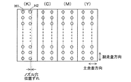
図7は、一般的な印刷ヘッドのノズル穴の配列を示す説明図である。
印刷ヘッドは、ブラック(K)、シアン(C)、マゼンダ(M)、イエロ(Y)の各色ごとにインクを吐出する4組のノズルアレイを備えており、各ノズルアレイは、副走査方向に2列に並んだ複数のノズル(図示省略)で構成されている。そして、各ノズルには1つずつノズル穴が設けられており、図7に示すように、これらノズル穴は、各色ごとに副走査方向に2列に並んで配列されている。なお、各ノズル穴の列の、設計上の中心位置を1点鎖線で示している。
印刷ヘッドの製造誤差により、図7に示すように、ブラック(K)のノズル穴の列のうち、右側の列の中心位置が、設計上の中心位置からずれている。なお、以下において、この中心位置がずれた右側のノズル穴の列を、単に「ノズル穴H2」と呼び、中心位置がずれていない左側のノズル穴の列を、単に「ノズル穴H1」と呼ぶ。
FIG. 7 is an explanatory diagram showing an arrangement of nozzle holes of a general print head.
The print head includes four nozzle arrays that eject ink for each color of black (K), cyan (C), magenta (M), and yellow (Y), and each nozzle array is arranged in the sub-scanning direction. It is composed of a plurality of nozzles (not shown) arranged in two rows. Each nozzle is provided with one nozzle hole. As shown in FIG. 7, these nozzle holes are arranged in two rows in the sub-scanning direction for each color. In addition, the design center position of each row of nozzle holes is indicated by a one-dot chain line.
Due to the manufacturing error of the print head, as shown in FIG. 7, the center position of the right column of the black (K) nozzle hole columns is shifted from the designed center position. In the following, the row of right nozzle holes whose center positions are shifted is simply referred to as “nozzle holes H2”, and the row of left nozzle holes whose center positions are not shifted is simply referred to as “nozzle holes H1”. .
図8は、図7に示すノズル穴H1,H2からインク滴が吐出されて印刷用紙に着弾する様子を示す説明図である。
図8において(A)はノズル穴H1から吐出されたブラック(K)のインク滴が印刷用紙Pに着弾する様子を示し、(B)はノズル穴H2から吐出されたブラック(K)のインク滴が印刷用紙Pに着弾する様子を示す。なお、図8において、インク穴H1及びH2は、図7におけるインク穴H1及びH2と同じであるので説明を省略する。
FIG. 8 is an explanatory diagram showing how ink droplets are ejected from the nozzle holes H1 and H2 shown in FIG. 7 and land on the printing paper.
8A shows a state in which black (K) ink droplets ejected from the nozzle hole H1 land on the printing paper P, and FIG. 8B shows black (K) ink droplets ejected from the nozzle hole H2. Shows a state where the ink lands on the printing paper P. In FIG. 8, the ink holes H1 and H2 are the same as the ink holes H1 and H2 in FIG.
図8に示す印刷ヘッドを搭載したプリンタは、印刷ヘッドを一方向に往復動作(主走査)させ、その往路と復路とで、それぞれインク滴を吐出する。そして、図8に示すように、ブラック(K)のインク滴は、往路でノズル穴H1から吐出され、復路でノズル穴H2から吐出される。
前述したように、ノズル穴H1は製造誤差による位置ずれがないので、図8(A)に示すように、ノズル穴H1から吐出されたインク滴は着弾予定位置に着弾する。一方、ノズル穴H2は製造誤差により位置がずれているために、ノズル穴H2から吐出されたインク滴は、図8(B)に示すように、着弾予定位置から印刷ヘッドの進行方向側にずれた位置に着弾する。
A printer equipped with the print head shown in FIG. 8 reciprocates (main scans) the print head in one direction, and ejects ink droplets in the forward path and the backward path, respectively. As shown in FIG. 8, black (K) ink droplets are ejected from the nozzle hole H1 in the forward path and from the nozzle hole H2 in the backward path.
As described above, since the nozzle hole H1 is not misaligned due to manufacturing errors, the ink droplets ejected from the nozzle hole H1 land at the expected landing position as shown in FIG. On the other hand, since the position of the nozzle hole H2 is shifted due to a manufacturing error, the ink droplets discharged from the nozzle hole H2 are shifted from the expected landing position to the traveling direction side of the print head as shown in FIG. 8B. Land at the target position.
図9は、図8に示す印刷用紙P上に形成されるドットを示す説明図である。
図9において、(A)は、ノズル穴H2の位置がずれていない場合に、印刷用紙P上に形成されるドットを示し、(B)は、図7に示すようにノズル穴H2の位置がずれた場合に、印刷用紙P上に形成されるドットを示す。
なお、図9において、L1〜L8は、ラスタ(主走査)ラインを示す。そして、奇数番目のラスタラインL1,L3,L5,L7のドットは往路で形成され、偶数番目のラスタラインL2,L4,L6,L8のドットは復路で形成される。なお、プリンタは、主走査が、往路から復路,及び復路から往路に変わる際、主走査方向と直交する方向(副走査方向)に印刷用紙Pを搬送する副走査を行う。
FIG. 9 is an explanatory diagram showing dots formed on the printing paper P shown in FIG.
9A shows dots formed on the printing paper P when the position of the nozzle hole H2 is not shifted, and FIG. 9B shows the position of the nozzle hole H2 as shown in FIG. The dots formed on the printing paper P when shifted are shown.
In FIG. 9, L1 to L8 indicate raster (main scanning) lines. The dots of odd-numbered raster lines L1, L3, L5, and L7 are formed in the forward path, and the dots of even-numbered raster lines L2, L4, L6, and L8 are formed in the backward path. The printer performs sub-scanning for transporting the printing paper P in a direction orthogonal to the main scanning direction (sub-scanning direction) when main scanning changes from the forward path to the backward path and from the backward path to the forward path.
仮に、ノズル穴H2の位置がずれていない場合、図9(A)に示すように、印刷用紙P上に形成されるドットは均等に散らばり、印刷ムラは発生しない。
一方、ノズル穴H2の位置がずれた場合、図9(A)と同じドットパターンとなるようにインク滴を吐出しても、偶数番目のラスタラインのドットの位置が左側にずれる。その結果、図9(B)に示すように、ドットが比較的密集した部分と、ドットが比較的離散した部分と、が主走査方向において明確になり、ドットが比較的密集した部分が濃く、ドットが比較的離散した部分が薄い印刷ムラが発生する。
If the position of the nozzle hole H2 is not displaced, as shown in FIG. 9A, dots formed on the printing paper P are evenly scattered, and printing unevenness does not occur.
On the other hand, when the position of the nozzle hole H2 is shifted, even if the ink droplets are ejected so as to have the same dot pattern as in FIG. 9A, the positions of the dots of the even-numbered raster lines are shifted to the left side. As a result, as shown in FIG. 9B, the portion where the dots are relatively dense and the portion where the dots are relatively discrete become clear in the main scanning direction, and the portion where the dots are relatively dense is dark. Print unevenness occurs where the dots are relatively discrete.
このような印刷ムラは、前述の印刷ヘッドの製造誤差の他、印刷ヘッドの取り付け誤差や、インクの吸収により生じた印刷媒体のしわ(いわゆるコックリング)などの要因で発生する場合がある。 Such print unevenness may occur due to factors such as print head mounting errors and print medium wrinkles (so-called cockling) caused by ink absorption, in addition to the aforementioned print head manufacturing errors.
なお、前述の特許文献1において、上述の印刷ムラの発生要因の1つであるコックリングを低減することが可能な印刷装置(プリンタ)が開示されているが、一般的なプリンタの構成に加えて、加熱処理装置を備える構成であるため、プリンタの大幅なコストアップを招いてしまう。 The above-mentioned Patent Document 1 discloses a printing apparatus (printer) that can reduce cockling, which is one of the causes of the above-described printing unevenness. In addition, since the heat treatment apparatus is provided, the cost of the printer is greatly increased.
本発明は、上述の課題を解決するためになされたものであり、印刷装置において、ドットの位置ずれに起因する印刷ムラの発生を、印刷装置等の大幅なコストアップなしに抑制することが可能な技術を提供することを目的とする。 The present invention has been made to solve the above-described problems, and in a printing apparatus, it is possible to suppress the occurrence of printing unevenness due to dot misalignment without significantly increasing the cost of the printing apparatus or the like. Aims to provide a new technology.
前述の課題の少なくとも一部を解決するために、本発明の第1の画像処理装置は、印刷媒体上に複数のドットを形成して画像を印刷する印刷装置について、前記複数のドットのオン/オフを指定するドットデータを生成する画像処理装置であって、前記印刷装置は、主走査方向の印刷解像度と副走査方向の印刷解像度との比が、少なくとも第1の比となるように、前記画像を印刷することが可能であり、前記画像処理装置は、少なくとも、前記第1の比に応じたハーフトーン処理用パラメータを用いて、前記画像を表す画像データに対してハーフトーン処理を施し、前記ドットデータを生成するハーフトーン処理部を備え、前記印刷装置が、前記ドットデータに基づいて、前記第1の比となるよう前記画像を印刷すると、印刷される前記画像に印刷ムラが発生し得る場合、前記ハーフトーン処理部は、前記第1の比とは異なる第2の比に応じた前記ハーフトーン処理用パラメータを用いて、前記画像データに対して前記ハーフトーン処理を施すことを要旨とする。 In order to solve at least a part of the above-described problems, a first image processing apparatus according to the present invention provides a printing apparatus that forms a plurality of dots on a print medium and prints an image. An image processing apparatus for generating dot data designating OFF, wherein the printing apparatus is configured such that a ratio of a printing resolution in a main scanning direction and a printing resolution in a sub-scanning direction is at least a first ratio. An image can be printed, and the image processing device performs halftone processing on image data representing the image using at least a halftone processing parameter corresponding to the first ratio, A halftone processing unit configured to generate the dot data, and the image to be printed when the printing apparatus prints the image to have the first ratio based on the dot data; When printing unevenness may occur, the halftone processing unit uses the halftone processing parameter according to a second ratio different from the first ratio to perform the halftone processing on the image data. The main point is to apply.
このように構成することで、本発明の第1の画像処理装置は、第1の比とは異なる第2の比に応じたハーフトーン処理用パラメータを用いてハーフトーン処理を施すので、生成されるドットデータにおいて、オンとなるドットの間隔は、第1の比に応じたハーフトーン処理用パラメータを用いた場合のドットデータにおける間隔と異なることとなる。
従って、第1の比に応じたハーフトーン処理用パラメータを用いて生成されるドットデータに基づいて印刷すると、形成されるドットの位置ずれに起因して、ドットの間隔が適切な間隔よりも狭くなる(若しくは広くなる)ことにより印刷ムラが生じ得る場合、印刷装置は、前述のような、第2の比に応じたハーフトーン処理用パラメータを用いて生成されるドットデータに基づいて印刷を行うので、形成されるドットの間隔を広げる(若しくは狭める)ことができ、印刷ムラの発生を抑制することができる。
With this configuration, the first image processing apparatus according to the present invention generates the halftone process using the halftone process parameter corresponding to the second ratio different from the first ratio. In the dot data, the interval between the dots that are turned on is different from the interval in the dot data when the halftone processing parameter corresponding to the first ratio is used.
Therefore, when printing is performed based on dot data generated using the halftone processing parameter corresponding to the first ratio, the dot interval is narrower than the appropriate interval due to the positional deviation of the formed dots. If printing unevenness may occur due to becoming (or becoming wider), the printing apparatus performs printing based on dot data generated using the halftone processing parameters according to the second ratio as described above. Therefore, the interval between the dots to be formed can be widened (or narrowed), and the occurrence of printing unevenness can be suppressed.
また、このように構成することで、印刷装置は、生成されたドットデータに基づいて第1の比となるよう印刷を行うので、一般的な印刷装置の構成とほぼ同じ構成となり、印刷装置の大幅なコストアップを抑えることができる。一方、画像処理装置においても、主走査方向の印刷解像度と副走査方向の印刷解像度との比に応じたハーフトーン処理用パラメータを用いてハーフトーン処理を施すので、ハーフトーン処理を行う一般的な画像処理装置とほぼ同じ構成となり、画像処理装置の大幅なコストアップを抑えることができる。 Also, with this configuration, the printing apparatus performs printing so as to achieve the first ratio based on the generated dot data, so the configuration is almost the same as the configuration of a general printing apparatus, and the printing apparatus Significant cost increase can be suppressed. On the other hand, in the image processing apparatus, halftone processing is performed using a halftone processing parameter corresponding to the ratio of the printing resolution in the main scanning direction and the printing resolution in the subscanning direction. The configuration is almost the same as that of the image processing apparatus, and a significant increase in cost of the image processing apparatus can be suppressed.
なお、本発明の第1の画像処理装置において、前記ハーフトーン処理用パラメータは、組織的ディザ法におけるディザマスクまたは濃度パターン法における閾値マトリクスであることが好ましい。 In the first image processing apparatus of the present invention, the halftone processing parameter is preferably a dither mask in a systematic dither method or a threshold matrix in a density pattern method.
これらのパラメータは、主走査方向の印刷解像度と副走査方向の印刷解像度との比に応じて異なる値が設定されており、異なる値の設定されたパラメータを用いてハーフトーン処理を行うことにより、主走査方向若しくは副走査方向でオンとなるドットの間隔が異なるドットデータを生成することが可能となる。 These parameters are set to different values depending on the ratio of the printing resolution in the main scanning direction and the printing resolution in the sub-scanning direction, and by performing halftone processing using the parameters set with different values, It is possible to generate dot data in which the interval between dots that are turned on in the main scanning direction or the sub-scanning direction is different.
また、本発明の第2の画像処理装置は、印刷媒体上に複数のドットを形成して画像を印刷する印刷装置について、前記複数のドットのオン/オフを指定するドットデータを生成する画像処理装置であって、前記印刷装置は、主走査方向の印刷解像度と副走査方向の印刷解像度との比が、少なくとも第1の比となるように、前記画像を印刷することが可能であり、前記画像処理装置は、少なくとも、前記第1の比に応じた第1のハーフトーン処理モジュールを用いて、前記画像を表す画像データに対してハーフトーン処理を施し、前記ドットデータを生成するハーフトーン処理部を備え、前記印刷装置が、前記ドットデータに基づいて、前記第1の比となるよう前記画像を印刷すると、印刷される前記画像に印刷ムラが生じ得る場合、前記ハーフトーン処理部は、前記第1の比とは異なる第2の比に応じた第2のハーフトーン処理モジュールを用いて、前記画像データに対して前記ハーフトーン処理を施すことを要旨とする。 According to another aspect of the present invention, there is provided an image processing apparatus for generating dot data for designating ON / OFF of the plurality of dots for a printing apparatus that prints an image by forming a plurality of dots on a print medium. The printing apparatus is capable of printing the image so that a ratio of a printing resolution in the main scanning direction to a printing resolution in the sub-scanning direction is at least a first ratio, The image processing apparatus performs halftone processing on image data representing the image using at least a first halftone processing module corresponding to the first ratio, and generates the dot data. And when the printing device prints the image so as to achieve the first ratio based on the dot data, the printed image may have uneven printing. Tone processing unit uses a second half-tone processing module in accordance with the second ratio different from the first ratio, is summarized in that performing the halftone process on the image data.
このように構成することで、本発明の第2の画像処理装置は、第1の比に応じた第1のハーフトーン処理モジュールとは異なる、第2の比に応じた第2のハーフトーン処理モジュールを用いてハーフトーン処理を施すので、生成されるドットデータにおいて、オンとなるドットの間隔は、第1のハーフトーン処理モジュールを用いた場合のドットデータにおける間隔と異なることとなる。
従って、第1のハーフトーン処理モジュールを用いて生成されるドットデータに基づいて第1の比となるよう印刷すると、形成されるドットの位置ずれに起因して、ドットの間隔が適切な間隔よりも狭くなる(若しくは広くなる)ことにより印刷ムラが生じ得る場合、印刷装置は、前述のような、第2のハーフトーン処理モジュールを用いて生成されるドットデータに基づいて印刷を行うので、形成されるドットの間隔を広げる(若しくは狭める)ことができ、印刷ムラの発生を抑制することができる。
With this configuration, the second image processing apparatus of the present invention is different from the first halftone processing module according to the first ratio, and the second halftone processing according to the second ratio. Since halftone processing is performed using a module, the interval between dots in the generated dot data is different from the interval in dot data when the first halftone processing module is used.
Therefore, when printing is performed so that the first ratio is based on the dot data generated using the first halftone processing module, the dot spacing is more appropriate than the proper spacing due to the positional deviation of the dots formed. If printing unevenness may occur due to narrowing (or widening), the printing apparatus performs printing based on dot data generated using the second halftone processing module as described above. It is possible to widen (or narrow) the interval between dots to be printed, and to suppress the occurrence of printing unevenness.
また、このように構成することで、印刷装置は、生成されたドットデータに基づいて第1の比となるよう印刷を行うので、一般的な印刷装置の構成とほぼ同じ構成となり、印刷装置の大幅なコストアップを抑えることができる。 Also, with this configuration, the printing apparatus performs printing so as to achieve the first ratio based on the generated dot data, so the configuration is almost the same as the configuration of a general printing apparatus, and the printing apparatus Significant cost increase can be suppressed.
なお、本発明の第2の画像処理装置において、前記ハーフトーン処理モジュールは、誤差拡散法によるハーフトーン処理を実行する誤差拡散処理部を備えることが好ましい。 In the second image processing apparatus of the present invention, it is preferable that the halftone processing module includes an error diffusion processing unit that performs halftone processing by an error diffusion method.
このように構成することで、ハーフトーン処理方法として周知の誤差拡散法を用いる、一般的な画像処理装置とほぼ同じ構成とすることができ、画像処理装置の大幅なコストアップを抑えることができる。 With this configuration, the configuration can be made substantially the same as that of a general image processing apparatus using a known error diffusion method as a halftone processing method, and a significant increase in cost of the image processing apparatus can be suppressed. .
なお、本発明は、上述した装置発明の態様に限ることなく、ドットデータ生成方法などの方法発明としての態様で実現することも可能である。さらには、それら方法や装置を構成するためのコンピュータプログラムとしての態様や、そのようなコンピュータプログラムを記録した記録媒体としての態様や、上記コンピュータプログラムを含み搬送波内に具現化されたデータ信号など、種々の態様で実現することも可能である。 Note that the present invention is not limited to the above-described apparatus invention, and can also be realized as a method invention such as a dot data generation method. Further, aspects as a computer program for configuring those methods and apparatuses, aspects as a recording medium recording such a computer program, data signals embodied in a carrier wave including the computer program, etc. It can also be realized in various ways.
本発明をコンピュータプログラムまたはそのプログラムを記録した記録媒体等として構成する場合には、画像処理装置を制御するプログラム全体として構成するものとしてもよいし、本発明の機能を果たす部分のみを構成するものとしてもよい。また、記録媒体としては、ROMカートリッジ、パンチカード、バーコードなどの符合が印刷された印刷物、コンピュータの内部記憶装置(RAMやROMなどのメモリ)および外部記憶装置などコンピュータが読み取り可能な種々の媒体を利用できる。 When the present invention is configured as a computer program or a recording medium that records the program, the entire program for controlling the image processing apparatus may be configured, or only the portion that performs the function of the present invention is configured. It is good. In addition, as a recording medium, various media that can be read by a computer such as a ROM cartridge, a punched card, a printed matter printed with a code such as a bar code, an internal storage device of a computer (memory such as RAM or ROM), and an external storage device Can be used.
以下、本発明を実施するための最良の形態を実施例に基づいて以下の順序で説明する。
A.第1の実施例
A−1.システム構成:
A−2.印刷ムラの抑制:
A−3.印刷データ生成処理:
A−4.実施例の効果:
B.第2の実施例:
B−1.システム構成:
B−2.印刷ムラの抑制:
B−3.印刷データ生成処理:
B−4.実施例の効果:
C.変形例:
C1.変形例1:〜C7.変形例7:
Hereinafter, the best mode for carrying out the present invention will be described in the following order based on examples.
A. First Example A-1. System configuration:
A-2. Control of uneven printing:
A-3. Print data generation processing:
A-4. Effects of the embodiment:
B. Second embodiment:
B-1. System configuration:
B-2. Control of uneven printing:
B-3. Print data generation processing:
B-4. Effects of the embodiment:
C. Variations:
C1. Modification 1: C7. Modification 7:
A.第1の実施例:
A−1.システム構成:
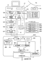
図1は、本発明の第1の実施例における印刷システムの概要構成を示す説明図である。プリンタPRTは、コンピュータPCに接続されており、コンピュータPC内のプリンタドライバ10で生成された印刷データを受け取って印刷を実行する。印刷データには、ラスタライン上の各画素についてドットのオン/オフを指定するためのラスタデータと、副走査時の印刷用紙の搬送量を特定するための副走査送り量データとが含まれる。なお、コンピュータPCは、請求項に記載の画像処理装置に相当し、ラスタデータは、請求項に記載のドットデータに相当する。
A. First embodiment:
A-1. System configuration:
FIG. 1 is an explanatory diagram showing a schematic configuration of a printing system according to the first embodiment of the present invention. The printer PRT is connected to the computer PC, and receives print data generated by the
コンピュータPCは、主として、ハードディスク11,CD−ROMドライブ12,フレキシブルディスクドライブ13の他、図示せざるCPU,メモリ,インタフェースカードを備えている。
コンピュータPCは、外部のネットワークTNに図示せざるインタフェースカードを介して接続されており、特定のサーバSVに接続することにより、プリンタPRTを駆動するためのプログラム及びデータをダウンロードすることができる。また、CD−ROMドライブ12やフレキシブルディスクドライブ13を用いて、必要なプログラム及びデータを、CD−ROMやフレキシブルディスクなどの記録媒体からロードすることもできる。なお、これらのプログラムは、印刷に必要なプログラム全体をまとめてロードする態様を採ることもできるし、一部の機能をモジュールとしてロードする態様を採ることもできる。
The computer PC mainly includes a
The computer PC is connected to an external network TN via an interface card (not shown), and can download a program and data for driving the printer PRT by connecting to a specific server SV. Further, using the CD-
コンピュータPCでは、所定のオペレーティングシステムの下、アプリケーションプログラムが動作している。このアプリケーションプログラムは、画像の生成やレタッチなどの処理を行う。オペレーティングシステムには、プリンタドライバ10が組み込まれている。このプリンタドライバ10は、副走査送り量データと、ラスタデータと、を含む印刷データを生成する機能を実現するためのプログラムである。
In the computer PC, an application program operates under a predetermined operating system. This application program performs processing such as image generation and retouching. A
そして、プリンタドライバ10は、印刷モード設定部101,マスク設定部102,画像データ入力部103,解像度変換部104,色変換部105,ハーフトーン処理部106,インタレースデータ生成部107を備えている。プリンタドライバ10は、アプリケーションプログラムから画像データを受け取り、プリンタPRTに供給する印刷データを生成する。
The
印刷モード設定部101は、印刷モードを選択するためのGUI(Graphical User Interface)を提供する。そして、ユーザが、図示せざるキーボードやマウス等を操作して、このGUIから印刷モードを選択すると、印刷モード設定部101は、選択された印刷モードを設定する。本実施例では、印刷モード設定部101において、以下の5種類の印刷モードが設定可能である。
(1)モード1:1440(dpi)× 360(dpi);
(2)モード2: 720(dpi)× 360(dpi);
(3)モード3: 360(dpi)× 360 (dpi);
(4)モード4: 360(dpi)× 720(dpi);
(5)モード5: 360(dpi)×1440(dpi);
各モードは、(主走査方向の印刷解像度)×(副走査方向の印刷解像度)で示されている。例えば、「モード1」では、主走査方向の印刷解像度が1440(dpi)であり、副走査方向の印刷解像度が360(dpi)である。
The print
(1) Mode 1: 1440 (dpi) × 360 (dpi);
(2) Mode 2: 720 (dpi) × 360 (dpi);
(3) Mode 3: 360 (dpi) × 360 (dpi);
(4) Mode 4: 360 (dpi) × 720 (dpi);
(5) Mode 5: 360 (dpi) × 1440 (dpi);
Each mode is indicated by (printing resolution in the main scanning direction) × (printing resolution in the sub-scanning direction). For example, in “mode 1”, the print resolution in the main scanning direction is 1440 (dpi), and the print resolution in the sub-scanning direction is 360 (dpi).
マスク設定部102は、後述する指定マスクデータmdと、印刷モード設定部101により設定された印刷モードと、に基づいて、ハーフトーン処理に用いられるディザマスク(ディザマトリクスとも言う)を設定する。なお、ハードディスク11には、以下の5種類のディザマスクが記憶されている。
(1)4:1用ディザマスクDM1;
(2)2:1用ディザマスクDM2;
(3)1:1用ディザマスクDM3;
(4)1:2用ディザマスクDM4;
(5)1:4用ディザマスクDM5;
各ディザマスクDM1〜DM5における「比」は、主走査方向の印刷解像度と副走査方向の印刷解像度との比(アスペクト比)を示す。なお、これらのディザマスクDM1〜DM5は、一般的なディザマスクであり、プリンタPRTのために特別に用意されたディザマスクではない。
The
(1) 4: 1 dither mask DM1;
(2) 2: 1 dither mask DM2;
(3) 1: 1 dither mask DM3;
(4) 1: 2 dither mask DM4;
(5) Dither mask DM5 for 1: 4;
The “ratio” in each of the dither masks DM1 to DM5 indicates a ratio (aspect ratio) between the printing resolution in the main scanning direction and the printing resolution in the sub-scanning direction. Note that these dither masks DM1 to DM5 are general dither masks and are not specially prepared for the printer PRT.
画像データ入力部103は、アプリケーションプログラムから、各画素についてのRGB(レッド,グリーン,ブルー)の階調値から成る画像データを入力する。
The image
解像度変換部104は、印刷モード設定部101で設定された印刷モードに応じて、アプリケーションプログラムが扱っている画像データの解像度を、プリンタドライバ10が扱う解像度に変換する。
The
色変換部105は、ハードディスク11に記憶されている図示せざる色変換テーブルを参照し、前述の画像データを、各画素についての、プリンタPRTが使用するブラック(K),シアン(C),マゼンタ(M),イエロ(Y)の各色の階調値(0〜255)から成るインク階調データに変換する。
The
ハーフトーン処理部106は、マスク設定部102で設定されたディザマスクを用い、周知の組織的ディザ法によって、前述のインク階調データにおける各画素の階調値を、ドットのオン/オフで表現するハーフトーン処理を行い、ラスタデータを生成する。
The
インタレースデータ生成部107は、ハーフトーン処理部106によって生成されたラスタデータと副走査送り量データとを、プリンタPRTに転送する所定のフォーマットに配列し、印刷データを生成する。
The interlace
一方、プリンタPRTは、主に、入力部201,バッファ202,指定マスクデータ格納部203,主走査部204,副走査部205,ヘッド駆動部206,印刷ヘッド207を備えている。
入力部201は、プリンタドライバ10から転送された印刷データを受け取る。この印刷データは、一旦、バッファ202に記憶される。そして、バッファ202に記憶された印刷データに基づいて、主走査部204及び副走査部205が、それぞれ印刷ヘッド207の主走査及び印刷用紙Pの搬送を行い、ヘッド駆動部206が、印刷ヘッド207を駆動してインク滴を吐出させ、印刷用紙Pにドットを形成して画像を印刷する。
指定マスクデータ格納部203は、後述する指定マスクデータmdを記憶する記憶装置である。
On the other hand, the printer PRT mainly includes an
The
The designated mask
なお、この印刷ヘッド207は、上述した印刷ヘッドと同じ構成であり、図7に示すノズル穴の配列を有する。すなわち、この印刷ヘッド207においても製造誤差により、ブラック(K)のノズル穴の列のうち、ノズル穴H2の位置が、設計上の位置からずれている。
また、このプリンタPRTは、上述したプリンタと同様に、主走査の往路と復路とでそれぞれインク滴を吐出し、奇数番目のラスタラインのドットを往路で形成して偶数番目のラスタラインのドットを復路で形成し、主走査が、往路から復路,及び復路から往路に変わる際に副走査を行う。
The
Similarly to the printer described above, this printer PRT ejects ink droplets in the forward and backward passes of main scanning, forms odd-numbered raster line dots in the forward path, and creates even-numbered raster line dots. Sub-scanning is performed when the main scanning is changed from the forward path to the backward path and from the backward path to the forward path.
A−2.印刷ムラの抑制:
前述したように、プリンタPRTは、上述したプリンタと同様な主走査及び副走査を行うので、従来と同じ印刷データに基づいて印刷を行った場合、図9(B)に示す印刷ムラが生じてしまう。
ここで、図9(B)に示す印刷ムラは、主走査方向に形成されるドットの間隔を広げるようにすれば解消される。そこで、本実施例では、ハーフトーン処理において、本来設定されるべきディザマスクと異なるディザマスクを用いることにより、主走査方向でドットがオンとなる画素の間隔が広がるようなラスタデータを生成し、このラスタデータを含む印刷データに基づいて印刷を行うことで、主走査方向に形成されるドットの間隔を広げて印刷ムラを抑制する。
以下、この印刷ムラの抑制について、図2,3を用いて具体的に説明する。
A-2. Control of uneven printing:
As described above, the printer PRT performs main scanning and sub-scanning similar to the above-described printer. Therefore, when printing is performed based on the same print data as the conventional printer, the printing unevenness shown in FIG. 9B occurs. End up.
Here, the printing unevenness shown in FIG. 9B can be eliminated by increasing the interval between dots formed in the main scanning direction. Therefore, in this embodiment, by using a dither mask that is different from the dither mask that should be originally set in the halftone process, raster data is generated so that the interval between pixels in which dots are turned on in the main scanning direction is widened. By performing printing based on the print data including the raster data, the interval between dots formed in the main scanning direction is widened to suppress printing unevenness.
Hereinafter, the suppression of the printing unevenness will be specifically described with reference to FIGS.
図2は、ハーフトーン処理で1:1用ディザマスクDM3を用い、モード3で印刷した場合に、印刷用紙Pに形成されるドットを示す説明図である。図2において上部は、1:1用ディザマスクDM3を示し、下部は、印刷用紙Pに形成されるドットを示す。
図2におけるL1〜L8は、図9におけるラスタラインL1〜L8と同じであるので説明を省略する。
FIG. 2 is an explanatory diagram showing dots formed on the printing paper P when printing is performed in the
L1 to L8 in FIG. 2 are the same as the raster lines L1 to L8 in FIG.
なお、以下において、ディザマスクは8×8の計64のセルから成るマトリクスである。そして、各セルには、それぞれ0〜255のうちのいずれかの数値が設定される。
なお、説明を分かり易くするために、128よりも小さい数値が設定されたセルをハッチングを施して図示する。
In the following, the dither mask is a matrix composed of a total of 64 cells of 8 × 8. Each cell is set with any numerical value from 0 to 255.
In order to make the explanation easy to understand, cells set with numerical values smaller than 128 are shown hatched.
例えば、360(dpi)×360(dpi)のように、主走査方向の単位長さあたりの画素数と、副走査方向の単位長さあたりの画素数と、が等しい場合、主走査方向においてドットが形成される画素の間隔(例えば、1画素おきにドットが形成)と、副走査方向においてドットが形成される間隔(例えば、1画素おきにドットが形成)と、が等しくなることで、ドットが主走査方向と副走査方向とで均等に散らばるように形成される。そして、1:1用ディザマスクDM3では、このようなドット形成が可能となるように、マトリクスの各セルの数値が設定されている。
従って、図2の上部に示すように、1:1用ディザマスクDM3において、128よりも小さい数値が設定されたセルの間隔は、主走査方向と副走査方向とで等しくなっている。
For example, when the number of pixels per unit length in the main scanning direction is equal to the number of pixels per unit length in the sub-scanning direction, such as 360 (dpi) × 360 (dpi), dot in the main scanning direction The interval between the pixels in which dots are formed (for example, dots are formed every other pixel) and the interval at which dots are formed in the sub-scanning direction (for example, dots are formed every other pixel) are the same. Are formed to be evenly distributed in the main scanning direction and the sub-scanning direction. In the 1: 1 dither mask DM3, the numerical value of each cell of the matrix is set so that such dot formation is possible.
Therefore, as shown in the upper part of FIG. 2, in the 1: 1 dither mask DM3, the interval between cells in which a numerical value smaller than 128 is set is equal in the main scanning direction and the sub-scanning direction.
このような1:1用ディザマスクDM3を用いて、全ての画素のインク階調値が「128」であるインク階調データに対してハーフトーン処理を施した場合、1:1用ディザマスクDM3におけるハッチングが施されたセルには、128よりも小さい数値が設定されているので、これらハッチングが施されたセルに対応する画素においてドットがオンとなるラスタデータが生成される。
そして、このラスタデータを含む印刷データに基づいて、アスペクト比が1:1のモード3(360(dpi)×360(dpi))で画像を印刷すると、図2の下部に示すように、図9(B)に示すのと同じ印刷ムラが生じてしまう。
When such a 1: 1 dither mask DM3 is used and halftone processing is performed on ink gradation data in which the ink gradation value of all pixels is “128”, the 1: 1 dither mask DM3 is used. Since the numerical value smaller than 128 is set for the hatched cells, raster data in which dots are turned on in the pixels corresponding to the hatched cells is generated.
Then, when an image is printed in mode 3 (360 (dpi) × 360 (dpi)) with an aspect ratio of 1: 1 based on the print data including the raster data, as shown in the lower part of FIG. The same printing unevenness as shown in (B) occurs.
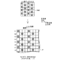
図3は、ハーフトーン処理で2:1用ディザマスクDM2を用い、モード3で印刷した場合に、印刷用紙Pに形成されるドットを示す説明図である。図3において上部は、2:1用ディザマスクDM2を示し、下部は、印刷用紙Pに形成されるドットを示す。
図3において、L1〜L8は、図9におけるラスタラインL1〜L8と同じであるので説明を省略する。
FIG. 3 is an explanatory diagram showing dots formed on the printing paper P when printing is performed in
In FIG. 3, L1 to L8 are the same as the raster lines L1 to L8 in FIG.
例えば、720(dpi)×360(dpi)のように、主走査方向の単位長さあたりの画素数が、副走査方向の単位長さあたりの画素数よりも多い場合、主走査方向においてドットが形成される画素の間隔(例えば、3画素おきにドットが形成)が、副走査方向においてドットが形成される間隔(例えば、1画素おきにドットが形成)よりも広くなることで、ドットが主走査方向と副走査方向とで均等に散らばるように形成される。そして、2:1用ディザマスクDM2では、このようなドット形成が可能となるように、マトリクスの各セルの数値が設定されている。
従って、図3の上部に示すように、2:1用ディザマスクDM2において、128よりも小さい数値が設定されたセルの間隔は、副走査方向よりも主走査方向が広くなっている。
For example, when the number of pixels per unit length in the main scanning direction is larger than the number of pixels per unit length in the sub-scanning direction, such as 720 (dpi) × 360 (dpi), dots are formed in the main scanning direction. The interval between formed pixels (for example, dots are formed every third pixel) becomes wider than the interval (for example, dots are formed every other pixel) in the sub-scanning direction. It is formed so as to be evenly scattered in the scanning direction and the sub-scanning direction. In the 2: 1 dither mask DM2, the numerical value of each cell of the matrix is set so that such dot formation is possible.
Therefore, as shown in the upper part of FIG. 3, in the 2: 1 dither mask DM2, the interval between cells set with a numerical value smaller than 128 is wider in the main scanning direction than in the sub-scanning direction.
このような2:1用ディザマスクDM2を用いて、全ての画素のインク階調値が「128」であるインク階調データに対してハーフトーン処理を施した場合、ハッチングが施されたセルに対応する画素でドットがオンとなるラスタデータが生成される。
そして、このラスタデータを含む印刷データに基づいて、アスペクト比が1:1のモード3(360(dpi)×360(dpi))で画像を印刷すると、偶数番目のラスタラインのドットは、ノズル穴H2の位置ずれにより左側に位置がずれるが、2:1用ディザマスクDM2を用いることにより、主走査方向に形成されるドットの間隔が、図2の下部に示すドットの間隔に比べて広くなるために、図2の下部に示すドットが比較的密集した部分に位置するドット同士が離れ、図3の下部に示すように、印刷ムラは生じない。
When such a 2: 1 dither mask DM2 is used and halftone processing is performed on ink gradation data in which the ink gradation value of all the pixels is “128”, the hatched cells are subjected to the halftone process. Raster data in which dots are turned on at corresponding pixels is generated.
When an image is printed in mode 3 (360 (dpi) × 360 (dpi)) with an aspect ratio of 1: 1 based on the print data including the raster data, the dots of the even-numbered raster lines are displayed in the nozzle holes. Although the position is shifted to the left side due to the displacement of H2, by using the 2: 1 dither mask DM2, the interval between dots formed in the main scanning direction becomes wider than the interval between dots shown in the lower part of FIG. For this reason, dots located in a portion where the dots shown in the lower part of FIG. 2 are relatively dense are separated from each other, and printing unevenness does not occur as shown in the lower part of FIG.
以上説明したように、図2に示すようなモード3における印刷ムラの発生は、ハーフトーン処理において、2:1用ディザマスクDM2を用いることで抑制することが可能となる。
As described above, the occurrence of uneven printing in
A−3.印刷データ生成処理:
プリンタPRTの出荷前に、図1に示すプリンタPRTの指定マスクデータ格納部203に、指定マスクデータmdが格納される。まず、この指定マスクデータmdについて説明する。
A-3. Print data generation processing:
Prior to shipment of the printer PRT, the designated mask data md is stored in the designated mask
図4は、指定マスクデータ格納部203に格納される指定マスクデータmdを示す説明図である。指定マスクデータmdは、印刷ムラが発生する印刷モードの情報と、その印刷ムラの発生を抑制するために使用すべきディザマスクの情報と、から成る。従って、前述のように、モード3での印刷ムラの発生が2:1用ディザマスクDM2の使用により抑制される場合、図4に示すように、指定マスクデータmdには、「モード3」及び「2:1用ディザマスク」の情報が登録される。
FIG. 4 is an explanatory diagram showing designated mask data md stored in the designated mask
そして、この指定マスクデータmdに登録される「印刷ムラが発生する印刷モード」及び「使用すべきディザマスク」は、以下のようにして決定される。すなわち、プリンタPRT出荷前の検査工程において、検査員が、各印刷モード毎に4:1用ディザマスクDM1,2:1用ディザマスクDM2,1:1用ディザマスクDM3,1:2用ディザマスクDM4,1:4用ディザマスクDM5と、ハーフトーン処理に用いるディザマスクを替えてテスト画像を印刷し、印刷ムラの発生する印刷モードと、その印刷ムラの発生を抑制することが可能なディザマスクを決定する。 The “print mode in which uneven printing occurs” and “the dither mask to be used” registered in the designated mask data md are determined as follows. That is, in the inspection process before shipment of the printer PRT, the inspector performs dither mask 4: 1 for dither DM1, 2: 1 dither mask DM2, 1: 1 dither mask DM3, 1: 2 dither mask for each printing mode. A test image is printed by changing the dither mask DM5 for DM4, 1: 4, and the dither mask used for the halftone process, and a dither mask capable of suppressing the occurrence of the printing unevenness by printing a test image. To decide.
このようにして決定された「印刷ムラが発生する印刷モード」及び「使用すべきディザマスク」の情報が指定マスクデータmdに登録され、この指定マスクデータmdが指定マスクデータ格納部203に格納されて、プリンタPRTが出荷される。
Information on the “print mode in which uneven printing occurs” and the “dither mask to be used” determined in this way are registered in the designated mask data md, and this designated mask data md is stored in the designated mask
続いて、印刷ムラの発生を抑制することが可能なラスタデータを含む印刷データの生成処理について、図5,6を用いて具体的に説明する。
図5は、第1の実施例における印刷データ生成処理の手順を示すフローチャートである。
今、ユーザが、アプリケーションプログラムにより処理した画像を、プリンタPRTで印刷するために、印刷モード設定部101が提供する前述のGUIから、印刷モードを「モード3(360(dpi)×360(dpi))」と選択して、プリンタドライバ10に、この画像の印刷を命令した。
Next, a process for generating print data including raster data capable of suppressing the occurrence of print unevenness will be specifically described with reference to FIGS.
FIG. 5 is a flowchart showing the procedure of print data generation processing in the first embodiment.
Now, in order to print an image processed by the application program with the printer PRT, the print mode is set to “mode 3 (360 (dpi) × 360 (dpi)” from the above-described GUI provided by the print
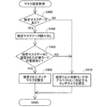
まず、印刷モード設定部101は、ユーザが選択した印刷モードを設定する(ステップS300)。具体的には、ユーザが選択した印刷モードの情報を、図示せざるメモリに記憶させて設定する。次に、マスク設定部102は、マスク設定処理を実行する(ステップS302)。ここで、このマスク設定処理について図6を用いて詳細に説明する。
First, the print
図6は、マスク設定部102により実行されるマスク設定処理の手順を示すフローチャートである。
まず、マスク設定部102は、プリンタPRTの指定マスクデータ格納部203に指定マスクデータmdが格納されているか否かを判定し(ステップS402)、格納されている場合には、その指定マスクデータmdを読み出す(ステップS404)。
FIG. 6 is a flowchart illustrating a procedure of mask setting processing executed by the
First, the
次に、マスク設定部102は、印刷モード設定部101によって設定された印刷モードの情報をメモリから読み出し、この設定された印刷モードが、指定マスクデータmdに登録されているか否かを判定する(ステップS406)。そして、登録されていると判定した場合、使用すべきディザマスクとして登録されているディザマスクを、ハードディスク11からメモリに読み出し、後述するハーフトーン処理で使用するディザマスクとして設定する(ステップS408)。
Next, the
具体的には、例えば、図4に示す指定マスクデータmdが、指定マスクデータ格納部203に格納されている場合、印刷モード設定部101によって設定された「モード3」が登録されているので、モード3において使用すべきディザマスクとして登録されている2:1用ディザマスクDM2を、ハードディスク11からメモリに読み出して設定する。
Specifically, for example, when the designated mask data md shown in FIG. 4 is stored in the designated mask
なお、指定マスクデータ格納部203に指定マスクデータmdが格納されていない場合、及び指定マスクデータmdに、設定された印刷モードが登録されていない場合には、マスク設定部102は、設定された印刷モードのアスペクト比に対応する、本来設定すべきディザマスクを設定する(ステップS410)。
Note that when the designated mask data md is not stored in the designated mask
具体的には、例えば、図4に示す指定マスクデータmdが、指定マスクデータ格納部203に格納されていて、印刷モード設定部101によって設定された印刷モードが、モード4(360(dpi)×720(dpi),アスペクト比=1:2)であった場合、指定マスクデータmdにモード4は登録されていないので、マスク設定部102は、1:2のアスペクト比に対応した1:2用ディザマスクDM4を、ハードディスク11からメモリに読み出して設定する。
Specifically, for example, the designated mask data md shown in FIG. 4 is stored in the designated mask
図5に戻って、次に、画像データ入力部103は、アプリケーションプログラムから、画像データを入力する(ステップS304)。次に、解像度変換部104は、メモリから印刷モード設定部101によって設定された印刷モードを読み出し、この印刷モードに応じて、画像データの解像度変換を行う(ステップS306)。前述のように、モード3が設定された場合、360(dpi)×360(dpi)となるように、解像度変換を行う。
Returning to FIG. 5, next, the image
次に、色変換部105は、前述の解像度変換された画像データについて、色変換を行う(ステップS308)。次に、ハーフトーン処理部106は、メモリからマスク設定部102によって設定されたディザマスクを読み出し、このディザマスクを用いてハーフトーン処理を行い、ラスタデータを生成する(ステップS310)。
前述したように、2:1用ディザマスクDM2が設定されている場合、ハーフトーン処理部106は、この2:1用ディザマスクDM2を用いてハーフトーン処理を行い、ラスタデータを生成する。
Next, the
As described above, when the 2: 1 dither mask DM2 is set, the
次に、インタレースデータ生成部107は、生成されたラスタデータを含む印刷データを生成する(ステップS312)。
そして、このようにして生成された印刷データは、プリンタPRTに転送され、プリンタPRTは、この印刷データに基づいて、モード3(360(dpi)×360(dpi))で画像を印刷する。
Next, the interlace
The print data generated in this way is transferred to the printer PRT, and the printer PRT prints an image in mode 3 (360 (dpi) × 360 (dpi)) based on the print data.
従って、2:1用ディザマスクDM2を用いてハーフトーン処理を行い、生成されたラスタデータを含む印刷データに基づいて、モード3(360(dpi)×360(dpi))で画像が印刷されるので、図3に示すように、印刷ムラの発生が抑制される。 Accordingly, halftone processing is performed using the 2: 1 dither mask DM2, and an image is printed in mode 3 (360 (dpi) × 360 (dpi)) based on the generated print data including raster data. Therefore, as shown in FIG. 3, the occurrence of uneven printing is suppressed.
A−4.実施例の効果:
以上説明したように、形成されるドットの位置がずれ、ドット間隔が主走査方向に狭まることで印刷ムラが発生する場合、本来設定すべきディザマスクとは異なるディザマスクの情報を指定マスクデータmdに登録し、この指定マスクデータmdをプリンタPRTの指定マスクデータ格納部203に格納しておく。そして、コンピュータPCは、ハーフトーン処理で用いるディザマスクを設定する際に、この指定マスクデータmdを読み出すことにより、本来設定すべきディザマスクとは異なるディザマスクを設定し、このディザマスクを用いてハーフトーン処理を行うことができる。
ここで、この「本来設定すべきディザマスクとは異なるディザマスク」は、このディザマスクを用いてハーフトーン処理を施して得られたラスタデータにおいて、主走査方向でドットがオンとなる画素の間隔が、本来設定すべきディザマスクを用いた場合に主走査方向でドットがオンとなる画素の間隔に比べて、より広くなるようなディザマスクである。
従って、プリンタPRTは、このようなディザマスクを用いたハーフトーン処理で生成されるラスタデータを含む印刷データに基づき、印刷を行うことになるので、形成されるドットの間隔は、主走査方向に広がることとなり、前述の印刷ムラの発生を抑制することが可能となる。
A-4. Effects of the embodiment:
As described above, when printing unevenness occurs because the position of the formed dots is shifted and the dot interval is narrowed in the main scanning direction, the dither mask information different from the dither mask to be originally set is designated mask data md. The designated mask data md is stored in the designated mask
Here, the “dither mask different from the dither mask to be originally set” is an interval between pixels in which dots are turned on in the main scanning direction in raster data obtained by performing halftone processing using the dither mask. However, when a dither mask that should be originally set is used, the dither mask is wider than the interval between pixels in which dots are turned on in the main scanning direction.
Accordingly, the printer PRT performs printing based on print data including raster data generated by halftone processing using such a dither mask. Therefore, the interval between dots to be formed is set in the main scanning direction. As a result, the occurrence of the printing unevenness described above can be suppressed.
更に、本実施例におけるプリンタの構成は、一般的なインクジェットプリンタの構成とほぼ同じであるので、プリンタの大幅なコストアップを抑えることができる。また、用いられるディザマスクも一般的なディザマスクである。従って、印刷システム全体の大幅なコストアップなしに、ドットの位置ずれに起因する印刷ムラの発生を抑制することができる。 Furthermore, the configuration of the printer in the present embodiment is almost the same as the configuration of a general ink jet printer, so that a significant cost increase of the printer can be suppressed. The dither mask used is also a general dither mask. Therefore, it is possible to suppress the occurrence of printing unevenness due to the positional deviation of dots without significantly increasing the cost of the entire printing system.
B.第2の実施例:
上述した第1の実施例においては、周知の組織的ディザ法によってハーフトーン処理を行っていたが、本実施例では、周知の誤差拡散法によってハーフトーン処理を行う。
B−1.システム構成:
図10は、本発明の第2の実施例における印刷システムの構成概要を示す説明図である。 本実施例において、図10に示す構成が、第1の実施例における図1に示した構成と異なる点について説明する。
B. Second embodiment:
In the first embodiment described above, halftone processing is performed by a known systematic dither method, but in this embodiment, halftone processing is performed by a known error diffusion method.
B-1. System configuration:
FIG. 10 is an explanatory diagram showing an outline of the configuration of the printing system according to the second embodiment of the present invention. In the present embodiment, a description will be given of differences between the configuration shown in FIG. 10 and the configuration shown in FIG. 1 in the first embodiment.
まず、コンピュータPCのプリンタドライバ15において、ハーフトーン処理部110は、図1に示すハーフトーン処理部106と異なり、アスペクト比に応じた、以下の5つの誤差拡散処理部を備えている。
(1)4:1用誤差拡散処理部GS1;
(2)2:1用誤差拡散処理部GS2;
(3)1:1用誤差拡散処理部GS3;
(4)1:2用誤差拡散処理部GS4;
(5)1:4用誤差拡散処理部GS5;
各誤差拡散処理部GS1〜GS5は、アスペクト比に応じて定められている誤差の拡散係数配列に基づき、周知の誤差拡散法によりハーフトーン処理を実行する。ハーフトーン処理部110は、これら誤差拡散処理部GS1〜GS5のうち、後述する誤差拡散処理部選択部111によって選択された誤差拡散処理部を用いてハーフトーン処理を行い、ラスタデータを生成する。
First, in the
(1) 4: 1 error diffusion processing unit GS1;
(2) 2: 1 error diffusion processing unit GS2;
(3) 1: 1 error diffusion processing unit GS3;
(4) 1: 2 error diffusion processing unit GS4;
(5) 1: 4 error diffusion processing unit GS5;
Each of the error diffusion processing units GS1 to GS5 executes halftone processing by a known error diffusion method based on an error diffusion coefficient array determined according to the aspect ratio. The
また、図1に示すマスク設定部102に代えて、誤差拡散処理部選択部111が備えられている。この誤差拡散処理部選択部111は、後述する処理部指定データsdと、印刷モード設定部101により設定された印刷モードと、に基づいて、ハーフトーン処理に用いる誤差拡散処理部を選択する。
Further, an error diffusion processing
また、本実施例では、誤差拡散法によりハーフトーン処理を行うことから、ハードディスク11に、ディザマスクは記憶されていない。
In this embodiment, since the halftone process is performed by the error diffusion method, no dither mask is stored in the
一方、プリンタPRTにおいては、指定マスクデータ格納部203に代えて、処理部指定データ格納部210が備えられている。そして、この処理部指定データ格納部210には、指定マスクデータmdに代えて、処理部指定データsdが格納される。
On the other hand, the printer PRT includes a processing unit designation
以上説明した構成以外は、図1に示した構成と同じであるので、同じ符合を付し、説明を省略する。また、同じ符合を付した機能部(例えば、印刷モード設定部101等)の実行する処理についても、上述の第1の実施例で説明した処理と同じであるので、説明を省略する。 Since the configuration other than the configuration described above is the same as the configuration shown in FIG. 1, the same reference numerals are given and the description is omitted. Also, the processing executed by the function units (for example, the print mode setting unit 101) having the same reference numerals is the same as the processing described in the first embodiment, and thus description thereof is omitted.
なお、本実施例におけるプリンタPRTの主走査及び副走査の動作は、第1の実施例におけるプリンタPRTの主走査及び副走査の動作と同じである。また、本実施例における印刷ヘッド207は、第1の実施例における印刷ヘッド207と同様に、ノズル穴の位置が図7に示すようにずれている。
The main scanning and sub scanning operations of the printer PRT in this embodiment are the same as the main scanning and sub scanning operations of the printer PRT in the first embodiment. Further, in the
B−2.印刷ムラの抑制:
上述のように、誤差の拡散係数配列はアスペクト比に応じて定められており、或る印刷モードのアスペクト比に応じた誤差の拡散係数配列に基づいて、誤差拡散法によりハーフトーン処理を実行すると、この印刷モードで印刷した場合に形成されるドットの間隔は、主走査方向と副走査方向とでほぼ等しくなる。
これは、例えば、副走査方向の印刷解像度よりも主走査方向の印刷解像度が高い印刷モードが設定され、この印刷モードのアスペクト比に応じた誤差の拡散係数配列に基づいて、誤差拡散法によりハーフトーン処理を実行した場合、主走査方向でドットがオンとなる画素の間隔が、副走査方向でドットがオンとなる画素の間隔よりも広くなるようなラスタデータが生成されるからである。
B-2. Control of uneven printing:
As described above, the error diffusion coefficient array is determined according to the aspect ratio, and when halftone processing is executed by the error diffusion method based on the error diffusion coefficient array corresponding to the aspect ratio of a certain printing mode. The interval between dots formed when printing in this print mode is substantially the same in the main scanning direction and the sub-scanning direction.
This is because, for example, a print mode in which the print resolution in the main scanning direction is higher than the print resolution in the sub-scanning direction is set. This is because when tone processing is executed, raster data is generated in which the interval between pixels in which dots are turned on in the main scanning direction is wider than the interval between pixels in which dots are turned on in the sub-scanning direction.
そして、このような「主走査方向でドットがオンとなる画素の間隔が、副走査方向でドットがオンとなる画素の間隔よりも広くなるようなラスタデータ」を、主走査方向の印刷解像度と副走査方向の印刷解像度とが等しい印刷モードで印刷すると、形成されるドットの間隔は、副走査方向に比べて主走査方向の方が広くなる。 Then, such “raster data in which the interval between pixels where dots are turned on in the main scanning direction is wider than the interval between pixels where dots are turned on in the sub-scanning direction” is referred to as the printing resolution in the main scanning direction. When printing is performed in a printing mode in which the printing resolution in the sub-scanning direction is equal, the interval between dots formed is wider in the main scanning direction than in the sub-scanning direction.
従って、モード3(アスペクト比=1:1)での印刷において、ドットの位置がずれて、図2の下部に示すような主走査方向の印刷ムラが発生する場合、ハーフトーン処理において、2:1用誤差拡散処理部GS2を用いてハーフトーン処理を実行し、生成されたラスタデータを含む印刷データに基づいて印刷を行うと、主走査方向に形成されるドットの間隔が広がることになるので、ドットの比較的密集した部分がなくなり、印刷ムラの発生を抑制することが可能となる。 Therefore, in printing in mode 3 (aspect ratio = 1: 1), if the dot position is shifted and printing unevenness in the main scanning direction as shown in the lower part of FIG. When halftone processing is executed using the error diffusion processing unit GS2 for 1 and printing is performed based on the generated print data including raster data, the interval between dots formed in the main scanning direction is increased. , The relatively dense portions of dots are eliminated, and the occurrence of uneven printing can be suppressed.
B−3.印刷データ生成処理:
プリンタPRTの出荷前に、図10に示す処理部指定データ格納部210に、処理部指定データsdが格納される。
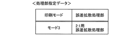
図11は、処理部指定データ格納部210に格納される処理部指定データsdを示す説明図である。処理部指定データsdは、印刷ムラが発生する印刷モードの情報と、その印刷ムラの発生を抑制するために用いるべき誤差拡散処理部の情報と、から成る。従って、上述のように、モード3での印刷ムラの発生が、2:1用誤差拡散処理部GS2を用いることで抑制される場合、図11に示すように、処理部指定データsdには、「モード3」及び「2:1用誤差拡散処理部」の情報が登録される。
B-3. Print data generation processing:
Prior to shipment of the printer PRT, the processing unit designation data sd is stored in the processing unit designation
FIG. 11 is an explanatory diagram showing the processing unit designation data sd stored in the processing unit designation
なお、この処理部指定データsdに登録される「印刷ムラが発生する印刷モード」及び「用いるべき誤差拡散処理部」は、第1の実施例において指定マスクデータmdに登録される情報と同様に、プリンタPRT出荷前の検査工程で行われるテスト印刷に基づき決定される。そして、処理部指定データsdが処理部指定データ格納部210に格納されて、プリンタPRTが出荷される。
The “print mode in which printing unevenness occurs” and the “error diffusion processing unit to be used” registered in the processing unit designation data sd are the same as the information registered in the designation mask data md in the first embodiment. The printer PRT is determined based on test printing performed in an inspection process before shipment. Then, the processing unit designation data sd is stored in the processing unit designation
続いて、印刷ムラの発生を抑制することが可能なラスタデータを含む印刷データの生成処理について、図12,図13を用いて具体的に説明する。
図12は、第2の実施例おける印刷データ生成処理の手順を示すフローチャートである。
今、ユーザが、上述の第1の実施例と同様に、アプリケーションプログラムにより処理した画像を、プリンタPRTで印刷するために、印刷モード設定部101が提供する前述のGUIから、印刷モードを「モード3(360(dpi)×360(dpi))」と選択して、プリンタドライバ10に、この画像の印刷を命令した。
Next, generation processing of print data including raster data that can suppress the occurrence of print unevenness will be specifically described with reference to FIGS.
FIG. 12 is a flowchart showing the procedure of print data generation processing in the second embodiment.
Now, in the same way as in the first embodiment, the user can print an image processed by an application program using the printer PRT from the aforementioned GUI provided by the print
まず、印刷モード設定部101は、ユーザが選択した印刷モードを設定する(ステップS500)。本処理は、図5に示すステップS300の処理と同じである。次に誤差拡散処理部選択部111は、誤差拡散処理部選択処理を実行する(ステップS502)。ここで、この誤差拡散処理部選択処理について図13を用いて詳細に説明する。
First, the print
図13は、誤差拡散処理部選択部111により実行される誤差拡散処理部選択処理の手順を示すフローチャートである。
まず、誤差拡散処理部選択部111は、プリンタPRTの処理部指定データ格納部210に処理部指定データsdが格納されているか否かを判定し(ステップS602)、格納されている場合には、その処理部指定データsdを読み出す(ステップS604)。
FIG. 13 is a flowchart illustrating a procedure of error diffusion processing unit selection processing executed by the error diffusion processing
First, the error diffusion processing
次に、誤差拡散処理部選択部111は、印刷モード設定部101によって設定された印刷モードの情報をメモリから読み出し、この設定された印刷モードが、処理部指定データsdに登録されているか否かを判定する(ステップS606)。そして、登録されていると判定した場合、用いるべき誤差拡散処理部として登録されている誤差拡散処理部を選択し、選択した誤差拡散処理部の情報をメモリに記憶させる(ステップS608)。
Next, the error diffusion processing
具体的には、例えば、図11に示す処理指定データsdが、処理部指定データ格納部210に格納されている場合、印刷モード設定部101によって設定された「モード3」が登録されているので、誤差拡散処理部選択部111は、登録されている2:1用誤差拡散処理部GS2を選択し、この2:1用誤差拡散処理部GS2の情報をメモリに記憶させる。
Specifically, for example, when the processing designation data sd shown in FIG. 11 is stored in the processing unit designation
なお、処理部指定データ格納部210に処理部指定データsdが格納されていない場合、及び処理部指定データsdに、設定された印刷モードが登録されていない場合には、誤差拡散処理部選択部111は、設定された印刷モードのアスペクト比に対応する、本来用いるべき誤差拡散処理部を選択し、選択した誤差拡散処理部の情報をメモリに記憶させる(ステップS610)。
When the processing unit designation data sd is not stored in the processing unit designation
図12に戻って、続くステップS504〜ステップS508の処理については、図5に示すステップS304〜ステップS308の処理と同じであるので説明を省略する。
次に、ハーフトーン処理部110は、誤差拡散処理部選択部111により選択された誤差拡散処理部の情報をメモリから読み出し、対応する誤差拡散処理部を用いてハーフトーン処理を行い、ラスタデータを生成する(ステップS510)。
前述のように、2:1用誤差拡散処理部GS2の情報がメモリに記憶されている場合、ハーフトーン処理部110は、この2:1用誤差拡散処理部GS2を用いてハーフトーン処理を行い、ラスタデータを生成する。
Returning to FIG. 12, the subsequent processing in step S504 to step S508 is the same as the processing in step S304 to step S308 shown in FIG.
Next, the
As described above, when the information of the 2: 1 error diffusion processing unit GS2 is stored in the memory, the
次に、インタレースデータ生成部107は、生成されたラスタデータを含む印刷データを生成する(ステップS512)。
そして、このようにして生成された印刷データは、プリンタPRTに転送され、プリンタPRTは、この印刷データに基づいて、モード3(360(dpi)×360(dpi))で画像を印刷する。
Next, the interlace
The print data generated in this way is transferred to the printer PRT, and the printer PRT prints an image in mode 3 (360 (dpi) × 360 (dpi)) based on the print data.
従って、2:1用誤差拡散処理部GS2が誤差拡散法によりハーフトーン処理を行い、生成されたラスタデータを含む印刷データに基づいて、モード3(アスペクト比=1:1)で画像が印刷されるので、上述したように、主走査方向の印刷ムラの発生が抑制される。 Therefore, the 2: 1 error diffusion processing unit GS2 performs halftone processing by the error diffusion method, and an image is printed in mode 3 (aspect ratio = 1: 1) based on the generated print data including raster data. Therefore, as described above, the occurrence of uneven printing in the main scanning direction is suppressed.
B−4.実施例の効果:
以上説明したように、形成されるドットの位置がずれ、ドット間隔が主走査方向に狭まることで印刷ムラが発生する場合、ハーフトーン処理において本来用いるべき誤差拡散処理部とは異なる誤差拡散処理部の情報を処理部指定データsdに登録し、この処理部指定データsdをプリンタPRTの処理部指定データ格納部210に格納しておく。そして、コンピュータPCは、ハーフトーン処理で用いる誤差拡散処理部を選択する際に、この処理部指定データsdを読み出すことにより、本来用いるべき誤差拡散処理部とは異なる誤差拡散処理部を選択し、この誤差拡散処理部を用いてハーフトーン処理を行うことができる。
ここで、この「本来用いるべき誤差拡散処理部とは異なる誤差拡散処理部」は、この誤差拡散処理部が誤差拡散法によるハーフトーン処理を実行して得られたラスタデータにおいて、主走査方向でドットがオンとなる画素の間隔が、本来用いるべき誤差拡散処理部が誤差拡散法を実行した場合に主走査方向でドットがオンとなる画素の間隔に比べて、より広くなるような誤差拡散処理部である。
従って、プリンタPRTは、このような誤差拡散処理部を用いたハーフトーン処理で生成されるラスタデータを含む印刷データに基づき、印刷を行うことになるので、形成されるドットの間隔は、主走査方向に広がることとなり、前述の印刷ムラの発生を抑制することが可能となる。
B-4. Effects of the embodiment:
As described above, when printing unevenness occurs due to misalignment of dots to be formed and dot intervals being narrowed in the main scanning direction, an error diffusion processing unit that is different from an error diffusion processing unit that should be originally used in halftone processing Is registered in the processing unit designation data sd, and this processing unit designation data sd is stored in the processing unit designation
Here, the “error diffusion processing unit different from the error diffusion processing unit that should be used originally” is the raster data obtained by executing the halftone processing by the error diffusion method by the error diffusion processing unit in the main scanning direction. Error diffusion processing in which the interval between pixels where dots are turned on is wider than the interval between pixels where dots are turned on in the main scanning direction when the error diffusion processing unit that should be used executes the error diffusion method Part.
Accordingly, since the printer PRT performs printing based on print data including raster data generated by halftone processing using such an error diffusion processing unit, the interval between dots to be formed is the main scan. It becomes possible to suppress the occurrence of the above-described printing unevenness.
更に、本実施例におけるプリンタの構成は、一般的なインクジェットプリンタの構成とほぼ同じであるので、プリンタの大幅なコストアップを抑えることができる。また、用いる誤差拡散処理部は周知の誤差拡散法によりハーフトーン処理を実行するので、一般的な誤差拡散処理を行う機能部とほぼ同じである。従って、印刷システム全体の大幅なコストアップなしに、ドットの位置ずれに起因する印刷ムラの発生を抑制することができる。 Furthermore, the configuration of the printer in the present embodiment is almost the same as the configuration of a general ink jet printer, so that a significant cost increase of the printer can be suppressed. Further, since the error diffusion processing unit to be used performs halftone processing by a well-known error diffusion method, it is almost the same as a functional unit that performs general error diffusion processing. Therefore, it is possible to suppress the occurrence of printing unevenness due to the positional deviation of dots without significantly increasing the cost of the entire printing system.
C.変形例:
なお、本発明は、上述の実施例や実施形態に限られるものではなく、その要旨を逸脱しない範囲において、種々の態様において実施することが可能であり、例えば以下のような変形も可能である。
C. Variations:
Note that the present invention is not limited to the above-described examples and embodiments, and can be implemented in various modes without departing from the scope of the invention. For example, the following modifications are possible. .
C1.変形例1:
上述の第1及び第2の実施例では、形成されるドットの位置が主走査方向にずれて主走査方向の印刷ムラが発生していたが、形成されるドットの位置が副走査方向にずれて副走査方向の印刷ムラが生じるような場合も、本発明を適用して、印刷ムラの発生を抑制することができる。
なお、このような副走査方向の印刷ムラは、例えば、ノズル穴の位置が設計上の位置から副走査方向にずれたり、紙送りローラの取付け不具合等で、印刷用紙の搬送量が設計上の搬送量と異なるといった要因で発生する。
C1. Modification 1:
In the first and second embodiments described above, the positions of the dots to be formed are shifted in the main scanning direction and printing unevenness occurs in the main scanning direction. However, the positions of the dots to be formed are shifted in the sub scanning direction. Even when printing unevenness occurs in the sub-scanning direction, the present invention can be applied to suppress the occurrence of printing unevenness.
Note that such uneven printing in the sub-scanning direction is caused by, for example, the amount of printing paper transported in the design due to the nozzle hole position deviating from the designed position in the sub-scanning direction or a paper feed roller mounting failure. It occurs due to factors such as different from the transport amount.
具体的には、例えば、モード3(360(dpi)×360(dpi),アスペクト比=1:1)において、副走査方向の印刷ムラが発生し、この印刷ムラが、上述のようにドット間隔を広げることにより抑制可能な印刷ムラの場合、ハーフトーン処理において、1:2用ディザマスクDM4や1:2用誤差拡散処理部GS4を用いるようにすればよい。このようにすることで、比較的密集した部分に位置するドット同士が副走査方向に離れるので、印刷ムラの発生を抑制することが可能となる。 Specifically, for example, in mode 3 (360 (dpi) × 360 (dpi), aspect ratio = 1: 1), printing unevenness occurs in the sub-scanning direction, and this printing unevenness is the dot interval as described above. In the case of printing unevenness that can be suppressed by widening, the 1: 2 dither mask DM4 or the 1: 2 error diffusion processing unit GS4 may be used in the halftone process. By doing so, dots located in relatively dense portions are separated from each other in the sub-scanning direction, so that occurrence of printing unevenness can be suppressed.
C2.変形例2:
上述の第1及び第2の実施例では、主走査方向のドット間隔を広げることにより印刷ムラを抑制していたが、印刷ムラによっては、主走査方向のドット間隔を狭めることにより、全体的に濃くして印刷ムラを抑制できる場合がある。このような場合においても、本発明を適用することができる。
C2. Modification 2:
In the first and second embodiments described above, the printing unevenness is suppressed by widening the dot interval in the main scanning direction. However, depending on the printing unevenness, the dot interval in the main scanning direction is reduced, so that In some cases, darkening can suppress printing unevenness. Even in such a case, the present invention can be applied.
図14は、主走査方向のドット間隔を狭めることにより、印刷ムラの発生を抑制する方法を模式的に示す説明図である。図14において、(A)は、ハーフトーン処理で2:1用ディザマスクDM2を用い、モード2(720(dpi)×360(dpi),アスペクト比=2:1)で印刷した場合に形成されるドットを示し、(B)は、ハーフトーン処理で1:1用ディザマスクDM3を用い、モード2(720(dpi)×360(dpi),アスペクト比=2:1)で印刷した場合に形成されるドットを示す。
図14(A)及び(B)において、左側は、2:1用ディザマスクDM2及び1:1用ディザマスクDM3を示し、右側は、全ての画素のインク階調値が「192」であるインク階調データについて、それぞれのディザマスクを用いてハーフトーン処理を施し、モード2で印刷した場合に形成されるドットを示す。
なお、図14において、2:1用ディザマスクDM2及び1:1用ディザマスクDM3においてハッチングを施したセルは、192よりも小さい数値が設定されたセルを示す。
FIG. 14 is an explanatory diagram schematically showing a method of suppressing the occurrence of printing unevenness by narrowing the dot interval in the main scanning direction. In FIG. 14, (A) is formed when printing is performed in mode 2 (720 (dpi) × 360 (dpi), aspect ratio = 2: 1) using a 2: 1 dither mask DM2 in halftone processing. (B) is formed when printing is performed in mode 2 (720 (dpi) × 360 (dpi), aspect ratio = 2: 1) using a 1: 1 dither mask DM3 in halftone processing. Indicates a dotted dot.
In FIGS. 14A and 14B, the left side shows the 2: 1 dither mask DM2 and the 1: 1 dither mask DM3, and the right side shows the ink gradation value of “192” for all pixels. For gradation data, dots formed when halftone processing is performed using each dither mask and printing is performed in
In FIG. 14, the hatched cells in the 2: 1 dither mask DM2 and the 1: 1 dither mask DM3 are cells in which numerical values smaller than 192 are set.
ここで、変形例2において、プリンタの走査および副走査の動作は、上述の実施例におけるプリンタPRTの走査および副走査の動作と同じである。また、変形例2におけるプリンタの印刷ヘッドは、上述の実施例における印刷ヘッドと同様に、ノズル穴H2の位置が図7に示すようにずれており、偶数番目のラスタラインのドットの位置が左側にずれる。 Here, in the second modification, the scanning and sub-scanning operations of the printer are the same as the scanning and sub-scanning operations of the printer PRT in the above-described embodiment. Further, in the printer head according to the second modification, the position of the nozzle hole H2 is shifted as shown in FIG. 7 as in the case of the print head in the above-described embodiment, and the dot positions of even-numbered raster lines are on the left side. Sneak away.
2:1用ディザマスクDM2を用いてハーフトーン処理を施し、モード2で印刷した結果、図14(A)に示すように、ドットが比較的密集した部分(濃い部分)と、ドットが比較的離散した部分(薄い部分)と、が主走査方向において明確になり、印刷ムラが発生する場合がある。
この場合、1:1用ディザマスクDM3をハーフトーン処理で用いるようにすれば、2:1用ディザマスクDM2を用いた場合に比べ、主走査方向のドット間隔を狭めて、より多くのドットを形成することができる。その結果、図14(B)に示すように、全体的に濃くなるため、ドットが比較的離散した部分が目立たなくなり、印刷ムラの発生を抑制することができる。
As a result of halftone processing using the 2: 1 dither mask DM2 and printing in
In this case, if the 1: 1 dither mask DM3 is used in the halftone process, the dot interval in the main scanning direction is narrowed and more dots are used than when the 2: 1 dither mask DM2 is used. Can be formed. As a result, as shown in FIG. 14B, since the entire color becomes dark, a portion where dots are relatively discrete becomes inconspicuous, and the occurrence of printing unevenness can be suppressed.
以上、組織的ディザ法によるハーフトーン処理の場合について説明したが、第2の実施例のように、誤差拡散法によるハーフトーン処理の場合についても、主走査方向のドット間隔を狭めることにより、全体的に濃くして印刷ムラの発生を抑制することができる。すなわち、2:1用誤差拡散処理部GS2を用いると、図14(A)に示すような印刷ムラが発生する場合には、1:1用誤差拡散処理部GS3を用いてハーフトーン処理を行うようにすれば、上述の組織的ディザ法によるハーフトーン処理の場合と同様に、全体に濃くなって、ドットが比較的離散した部分が目立たなくなり、印刷ムラの発生を抑制することができる。 As described above, the case of the halftone processing by the systematic dither method has been described. However, in the case of the halftone processing by the error diffusion method as in the second embodiment, the entire dot width in the main scanning direction can be reduced by reducing the dot interval. Therefore, it is possible to suppress the occurrence of uneven printing. That is, when the 2: 1 error diffusion processing unit GS2 is used and printing unevenness as shown in FIG. 14A occurs, halftone processing is performed using the 1: 1 error diffusion processing unit GS3. By doing so, as in the case of the halftone process using the above-described systematic dither method, the entire image becomes darker and the portion where dots are relatively discrete becomes inconspicuous, and the occurrence of printing unevenness can be suppressed.
なお、印刷ムラの発生を、このように、ドット間隔を狭めることにより抑制することができるか、又は、上述の実施例のように、ドット間隔を広げることにより抑制することができるかは、実際にテスト印刷を行って判断する。そして、上述の第1及び第2の実施例のように、印刷ムラの発生を抑制することが可能なディザマスク及び誤差拡散処理部を決定して、指定マスクデータ及び処理部指定データに登録する。 Whether the occurrence of uneven printing can be suppressed by narrowing the dot interval as described above or whether the dot interval can be increased as in the above-described embodiment is actually And make a test print. Then, as in the first and second embodiments described above, a dither mask and an error diffusion processing unit that can suppress the occurrence of uneven printing are determined and registered in the designated mask data and the processing unit designation data. .
C3.変形例3:
上述の第1の実施例では、ハーフトーン処理において、組織的ディザ法を用いるものとしたが、これに限らない。濃度パターン法など、アスペクト比に応じたパラメータを用いる他の処理方法を用いても構わない。濃度パターン法で用いる階調毎の閾値マトリクス等のパラメータも、前述の組織的ディザ法におけるディザマスクと同様に、各印刷モードのアスペクト比に応じて用意されており、これらパラメータとして設定される値は、ディザマスクを用いた場合と同様なラスタデータが得られるように定められているからである。
C3. Modification 3:
In the first embodiment described above, the systematic dither method is used in the halftone process, but the present invention is not limited to this. Other processing methods that use parameters according to the aspect ratio, such as a density pattern method, may be used. Parameters such as a threshold matrix for each gradation used in the density pattern method are prepared according to the aspect ratio of each printing mode, as in the dither mask in the above-described systematic dither method, and values set as these parameters This is because it is determined that raster data similar to that obtained when a dither mask is used can be obtained.
C4.変形例4:
上述の第1の実施例では、図2に示す主走査方向の印刷ムラの発生を抑制するために2:1用ディザマスクDM2を用いていたが、2:1用ディザマスクDM2に代えて、4:1用ディザマスクDM1を用いるようにしてもよい。4:1用ディザマスクDM1を用いた場合も、2:1用ディザマスクDM2を用いた場合と同様に、主走査方向に形成されるドットの間隔が、1:1用ディザマスクDM3を用いた場合のドットの間隔に比べて広くなるように、ドットを形成することが可能となるからである。
また、第2の実施例においても、2:1用誤差拡散処理部GS2に代えて、4:1用誤差拡散処理部GS1を用いるようにしてもよい。
C4. Modification 4:
In the first embodiment described above, the 2: 1 dither mask DM2 is used to suppress the occurrence of uneven printing in the main scanning direction shown in FIG. 2, but instead of the 2: 1 dither mask DM2, A 4: 1 dither mask DM1 may be used. In the case of using the 4: 1 dither mask DM1, as in the case of using the 2: 1 dither mask DM2, the interval between the dots formed in the main scanning direction uses the 1: 1 dither mask DM3. This is because the dots can be formed so as to be wider than the dot interval in this case.
In the second embodiment, a 4: 1 error diffusion processing unit GS1 may be used instead of the 2: 1 error diffusion processing unit GS2.
C5.変形例5:
上述の第1及び第2の実施例では、プリンタPRTは、主走査の往路と復路とでそれぞれインク滴を吐出するものとしたが、片路だけでインク滴を吐出するプリンタPRTであっても構わない。
また、プリンタPRTは、奇数番目のラスタラインのドットを往路で形成して偶数番目のラスタラインのドットを復路で形成し、主走査が、往路から復路又は復路から往路に変わる際に副走査を行うものとしたが、これに限らず、例えば、全てのラスタラインについて、奇数列のドットを往路で形成して、偶数列のドットを復路で形成し、1往復する毎に副走査を行ってもよい。
C5. Modification 5:
In the first and second embodiments described above, the printer PRT ejects ink droplets in the forward and backward passes of main scanning. However, even if the printer PRT ejects ink droplets in only one passage, I do not care.
Also, the printer PRT forms odd-numbered raster line dots in the forward path and even-numbered raster line dots in the backward path, and performs sub-scanning when main scanning changes from the forward path to the backward path or from the backward path to the forward path. However, the present invention is not limited to this. For example, for all raster lines, odd-numbered dots are formed in the forward path, even-numbered dots are formed in the backward path, and sub-scanning is performed each time one round trip is performed. Also good.
C6.変形例6:
上述の第1及び第2の実施例では、インクジェットプリンタについて説明したが、本発明は、インクジェットプリンタに限らず、組織的ディザ法や誤差拡散法等によりハーフトーン処理を行い、ドットを形成して印刷を行う種々の印刷装置に適用可能である。
C6. Modification 6:
In the first and second embodiments described above, the ink jet printer has been described. However, the present invention is not limited to the ink jet printer, and halftone processing is performed by a systematic dither method, an error diffusion method, or the like to form dots. The present invention can be applied to various printing apparatuses that perform printing.
C7.変形例7:
上述の第1及び第2の実施例において、ソフトウェアによって実現されていた構成の一部を、ハードウェアに置き換えるようにしてもよい。例えば、上述のハーフトーン処理を、ハーフトーン処理回路によって行わせるようにしてもよい。
C7. Modification 7:
In the first and second embodiments described above, a part of the configuration realized by software may be replaced with hardware. For example, the above halftone processing may be performed by a halftone processing circuit.
10,15...プリンタドライバ
11...ハードディスク
12...CD−ROMドライブ
13...フレキシブルディスクドライブ
101...印刷モード設定部
102...マスク設定部
103...画像データ入力部
104...解像度変換部
105...色変換部
106,110...ハーフトーン処理部
107...インタレースデータ生成部
110...誤差拡散処理部選択部
201...入力部
202...バッファ
203...指定マスクデータ格納部
204...主走査部
205...副走査部
206...ヘッド駆動部
207...印刷ヘッド
210...処理部指定データ格納部
DM1...4:1用ディザマスク
DM2...2:1用ディザマスク
DM3...1:1用ディザマスク
DM4...1:2用ディザマスク
DM5...1:4用ディザマスク
GS1...4:1用誤差拡散処理部
GS2...2:1用誤差拡散処理
GS3...1:1用誤差拡散処理部
GS4...1:2用誤差拡散処理部
GS5...1:4用誤差拡散処理部
md...指定マスクデータ
P...印刷用紙
PC...コンピュータ
PRT...プリンタ
sd...処理部指定データ
SV...サーバ
TN...ネットワーク
L1〜L8...ラスタライン
H1,H2...ノズル穴
DESCRIPTION OF
Claims (9)
前記印刷装置は、主走査方向の印刷解像度と副走査方向の印刷解像度との比が、少なくとも第1の比となるように、前記画像を印刷することが可能であり、
前記画像処理装置は、
少なくとも、前記第1の比に応じたハーフトーン処理用パラメータを用いて、前記画像を表す画像データに対してハーフトーン処理を施し、前記ドットデータを生成するハーフトーン処理部を備え、
前記印刷装置が、前記ドットデータに基づいて、前記第1の比となるよう前記画像を印刷すると、印刷される前記画像に印刷ムラが発生し得る場合、前記ハーフトーン処理部は、前記第1の比とは異なる第2の比に応じた前記ハーフトーン処理用パラメータを用いて、前記画像データに対して前記ハーフトーン処理を施すことを特徴とする画像処理装置。 An image processing apparatus that generates dot data that specifies ON / OFF of the plurality of dots, for a printing apparatus that prints an image by forming a plurality of dots on a print medium,
The printing apparatus is capable of printing the image so that a ratio of a printing resolution in the main scanning direction and a printing resolution in the sub-scanning direction is at least a first ratio,
The image processing apparatus includes:
At least using a halftone processing parameter according to the first ratio, a halftone processing unit that performs halftone processing on image data representing the image and generates the dot data,
When the printing apparatus prints the image based on the dot data so as to have the first ratio, if the printing unevenness may occur in the printed image, the halftone processing unit An image processing apparatus, wherein the halftone process is performed on the image data using the halftone processing parameter corresponding to a second ratio different from the ratio.
前記ハーフトーン処理用パラメータは、組織的ディザ法におけるディザマスクまたは濃度パターン法における閾値マトリクスであることを特徴とする画像処理装置。 The image processing apparatus according to claim 1,
The halftone processing parameter is a dither mask in a systematic dither method or a threshold matrix in a density pattern method.
前記印刷装置は、主走査方向の印刷解像度と副走査方向の印刷解像度との比が、少なくとも第1の比となるように、前記画像を印刷することが可能であり、
前記画像処理装置は、
少なくとも、前記第1の比に応じた第1のハーフトーン処理モジュールを用いて、前記画像を表す画像データに対してハーフトーン処理を施し、前記ドットデータを生成するハーフトーン処理部を備え、
前記印刷装置が、前記ドットデータに基づいて、前記第1の比となるよう前記画像を印刷すると、印刷される前記画像に印刷ムラが生じ得る場合、前記ハーフトーン処理部は、前記第1の比とは異なる第2の比に応じた第2のハーフトーン処理モジュールを用いて、前記画像データに対して前記ハーフトーン処理を施すことを特徴とする画像処理装置。 An image processing apparatus that generates dot data that specifies ON / OFF of the plurality of dots, for a printing apparatus that prints an image by forming a plurality of dots on a print medium,
The printing apparatus is capable of printing the image so that a ratio of a printing resolution in the main scanning direction and a printing resolution in the sub-scanning direction is at least a first ratio,
The image processing apparatus includes:
At least, using a first halftone processing module according to the first ratio, a halftone processing unit that performs halftone processing on image data representing the image and generates the dot data,
When the printing apparatus prints the image based on the dot data so as to have the first ratio, when the printed image may have uneven printing, the halftone processing unit An image processing apparatus that performs the halftone process on the image data using a second halftone processing module according to a second ratio different from the ratio.
前記ハーフトーン処理モジュールは、誤差拡散法によるハーフトーン処理を実行する誤差拡散処理部を備えることを特徴とする画像処理装置。 The image processing apparatus according to claim 3,
The halftone processing module includes an error diffusion processing unit that performs halftone processing by an error diffusion method.
所定のハーフトーン処理用パラメータを用いて、前記画像を表す画像データに対してハーフトーン処理を施し、前記ドットデータを生成する工程を備え、
前記生成工程では、前記第1の比に応じたハーフトーン処理用パラメータを用いて生成したドットデータに基づいて、前記印刷装置が前記第1の比となるよう前記画像を印刷すると、印刷される前記画像に印刷ムラが発生し得る場合、前記第1の比とは異なる第2の比に応じた前記ハーフトーン処理用パラメータを用いて、前記画像データに対して前記ハーフトーン処理を施すことを特徴とするドットデータ生成方法。 The image is printed by forming a plurality of dots on the print medium, and the image is printed so that the ratio of the print resolution in the main scanning direction and the print resolution in the sub-scanning direction is at least the first ratio. A dot data generation method for generating dot data for designating ON / OFF of the plurality of dots for a printing apparatus capable of
Using predetermined halftone processing parameters, performing halftone processing on image data representing the image, and generating the dot data,
In the generation step, printing is performed when the printing apparatus prints the image so as to have the first ratio based on dot data generated using a halftone processing parameter corresponding to the first ratio. When printing unevenness may occur in the image, the halftone processing is performed on the image data using the halftone processing parameter according to a second ratio different from the first ratio. Characteristic dot data generation method.
所定のハーフトーン処理モジュールを用いて、前記画像を表す画像データに対してハーフトーン処理を施し、前記ドットデータを生成する工程を備え、
前記生成工程では、前記第1の比に応じた第1のハーフトーン処理モジュールを用いて生成したドットデータに基づいて、前記印刷装置が前記第1の比となるよう前記画像を印刷すると、印刷される前記画像に印刷ムラが発生し得る場合、前記第1の比とは異なる第2の比に応じた第2のハーフトーン処理モジュールを用いて、前記画像データに対して前記ハーフトーン処理を施すことを特徴とするドットデータ生成方法。 The image is printed by forming a plurality of dots on the print medium, and the image is printed so that the ratio of the print resolution in the main scanning direction and the print resolution in the sub-scanning direction is at least the first ratio. A dot data generation method for generating dot data for designating ON / OFF of the plurality of dots for a printing apparatus capable of
Using a predetermined halftone processing module, performing halftone processing on image data representing the image, and generating the dot data;
In the generating step, when the printing apparatus prints the image so as to have the first ratio based on dot data generated using the first halftone processing module corresponding to the first ratio, If printing unevenness may occur in the image, the halftone processing is performed on the image data using a second halftone processing module according to a second ratio different from the first ratio. Dot data generation method characterized by performing.
所定のハーフトーン処理用パラメータを用いて、前記画像を表す画像データに対してハーフトーン処理を施し、前記ドットデータを生成する機能と、
前記第1の比に応じたハーフトーン処理用パラメータを用いて生成したドットデータに基づいて、前記印刷装置が前記第1の比となるよう前記画像を印刷すると、印刷される前記画像に印刷ムラが発生し得る場合、前記第1の比とは異なる第2の比に応じた前記ハーフトーン処理用パラメータを用いて、前記画像データに対して前記ハーフトーン処理を施し、前記ドットデータを生成する機能と、
をコンピュータに実現させるためのプログラム。 The image is printed by forming a plurality of dots on the print medium, and the image is printed so that the ratio of the print resolution in the main scanning direction and the print resolution in the sub-scanning direction is at least the first ratio. A computer program for generating dot data for specifying on / off of the plurality of dots for a printing apparatus capable of
A function of performing halftone processing on image data representing the image using predetermined halftone processing parameters and generating the dot data;
When the printing apparatus prints the image so that the first ratio becomes the first ratio based on the dot data generated using the halftone processing parameter corresponding to the first ratio, the print unevenness is printed on the printed image. Can occur, the halftone process is performed on the image data using the halftone process parameter corresponding to a second ratio different from the first ratio, and the dot data is generated. Function and
A program to make a computer realize.
所定のハーフトーン処理モジュールを用いて、前記画像を表す画像データに対してハーフトーン処理を施し、前記ドットデータを生成する機能と、
前記第1の比に応じた第1のハーフトーン処理モジュールを用いて生成したドットデータに基づいて、前記印刷装置が前記第1の比となるよう前記画像を印刷すると、印刷される前記画像に印刷ムラが発生し得る場合、前記第1の比とは異なる第2の比に応じた第2のハーフトーン処理モジュールを用いて、前記画像データに対して前記ハーフトーン処理を施し、前記ドットデータを生成する機能と、
をコンピュータに実現させるためのプログラム。 The image is printed by forming a plurality of dots on the print medium, and the image is printed so that the ratio of the print resolution in the main scanning direction and the print resolution in the sub-scanning direction is at least the first ratio. A computer program for generating dot data for specifying on / off of the plurality of dots for a printing apparatus capable of
A function of performing halftone processing on image data representing the image using a predetermined halftone processing module, and generating the dot data;
Based on the dot data generated using the first halftone processing module corresponding to the first ratio, when the printing apparatus prints the image so as to have the first ratio, the printed image When printing unevenness may occur, the halftone process is performed on the image data using a second halftone processing module according to a second ratio different from the first ratio, and the dot data With the ability to generate
A program to make a computer realize.
Priority Applications (2)
| Application Number | Priority Date | Filing Date | Title |
|---|---|---|---|
| JP2004204155A JP2006033006A (en) | 2004-07-12 | 2004-07-12 | Image processing device and dot data generation method |
| US11/177,485 US7532362B2 (en) | 2004-07-12 | 2005-07-11 | Image processing device and dot data generation method |
Applications Claiming Priority (1)
| Application Number | Priority Date | Filing Date | Title |
|---|---|---|---|
| JP2004204155A JP2006033006A (en) | 2004-07-12 | 2004-07-12 | Image processing device and dot data generation method |
Publications (2)
| Publication Number | Publication Date |
|---|---|
| JP2006033006A true JP2006033006A (en) | 2006-02-02 |
| JP2006033006A5 JP2006033006A5 (en) | 2007-08-30 |
Family
ID=35541033
Family Applications (1)
| Application Number | Title | Priority Date | Filing Date |
|---|---|---|---|
| JP2004204155A Pending JP2006033006A (en) | 2004-07-12 | 2004-07-12 | Image processing device and dot data generation method |
Country Status (2)
| Country | Link |
|---|---|
| US (1) | US7532362B2 (en) |
| JP (1) | JP2006033006A (en) |
Cited By (3)
| Publication number | Priority date | Publication date | Assignee | Title |
|---|---|---|---|---|
| JP2007281870A (en) * | 2006-04-06 | 2007-10-25 | Konica Minolta Holdings Inc | Image forming apparatus, image formation method, and image forming program |
| JP2008023893A (en) * | 2006-07-24 | 2008-02-07 | Seiko Epson Corp | Image processing apparatus for performing bidirectional printing and printing apparatus |
| WO2015050245A1 (en) * | 2013-10-04 | 2015-04-09 | 富士フイルム株式会社 | Image processing device, printing apparatus, image processing method, and program |
Families Citing this family (6)
| Publication number | Priority date | Publication date | Assignee | Title |
|---|---|---|---|---|
| JP2007306513A (en) * | 2005-07-13 | 2007-11-22 | Konica Minolta Business Technologies Inc | Method and device for image data compression |
| JP2007276449A (en) * | 2006-03-15 | 2007-10-25 | Ricoh Co Ltd | Setting method, image recording device, program, and recording medium |
| JP2009083102A (en) * | 2007-09-27 | 2009-04-23 | Canon Inc | Inkjet recording apparatus and inkjet recording method |
| JP5247492B2 (en) * | 2009-01-20 | 2013-07-24 | キヤノン株式会社 | Image forming apparatus, control method, and program |
| JP5304587B2 (en) * | 2009-10-23 | 2013-10-02 | セイコーエプソン株式会社 | Liquid ejection apparatus and liquid ejection method |
| CN111730995B (en) * | 2019-08-23 | 2022-04-26 | 深圳市汉森软件有限公司 | Scanning type ink-jet printing control method, device, equipment and storage medium |
Family Cites Families (10)
| Publication number | Priority date | Publication date | Assignee | Title |
|---|---|---|---|---|
| JPH08132724A (en) | 1994-11-08 | 1996-05-28 | Canon Inc | Ink-jet recording method and its device |
| JPH09219794A (en) | 1996-02-14 | 1997-08-19 | Canon Inc | Image processing method and its device and printing device and its system |
| JPH11240202A (en) | 1997-12-25 | 1999-09-07 | Canon Inc | Image-recording apparatus and copying system |
| JPH11208031A (en) | 1998-01-28 | 1999-08-03 | Konica Corp | Image recording apparatus |
| JP2000004368A (en) | 1998-06-15 | 2000-01-07 | Seiko Epson Corp | Print controller, print control method and medium with print control program recorded therein |
| JP2001126059A (en) * | 1999-10-25 | 2001-05-11 | Ricoh Co Ltd | Halftone screening method |
| JP2001293905A (en) | 2000-04-11 | 2001-10-23 | Brother Ind Ltd | Printer and storage medium |
| JP2002160353A (en) | 2000-11-24 | 2002-06-04 | Canon Inc | Image recording apparatus, print system, and method of correcting nonuniformities in density of ink-jet head |
| US6471332B1 (en) * | 2001-01-31 | 2002-10-29 | Hewlett-Packard Company | Multiple marker inkjet printing for increased print speed |
| JP4003046B2 (en) | 2002-02-21 | 2007-11-07 | セイコーエプソン株式会社 | PRINT CONTROL DEVICE, PRINT CONTROL METHOD, PRINT SYSTEM, PRINT CONTROL PROGRAM, AND MEDIUM CONTAINING PRINT CONTROL PROGRAM |
-
2004
- 2004-07-12 JP JP2004204155A patent/JP2006033006A/en active Pending
-
2005
- 2005-07-11 US US11/177,485 patent/US7532362B2/en not_active Expired - Fee Related
Cited By (8)
| Publication number | Priority date | Publication date | Assignee | Title |
|---|---|---|---|---|
| JP2007281870A (en) * | 2006-04-06 | 2007-10-25 | Konica Minolta Holdings Inc | Image forming apparatus, image formation method, and image forming program |
| JP4552882B2 (en) * | 2006-04-06 | 2010-09-29 | コニカミノルタホールディングス株式会社 | Image forming apparatus, image forming method, and image forming program |
| JP2008023893A (en) * | 2006-07-24 | 2008-02-07 | Seiko Epson Corp | Image processing apparatus for performing bidirectional printing and printing apparatus |
| JP4675296B2 (en) * | 2006-07-24 | 2011-04-20 | セイコーエプソン株式会社 | Printing apparatus and printing method |
| WO2015050245A1 (en) * | 2013-10-04 | 2015-04-09 | 富士フイルム株式会社 | Image processing device, printing apparatus, image processing method, and program |
| JP2015076627A (en) * | 2013-10-04 | 2015-04-20 | 富士フイルム株式会社 | Image processing device, printer, image processing method and program |
| US9571695B2 (en) | 2013-10-04 | 2017-02-14 | Fujifilm Corporation | Image processing device adapting halftone process to plural printing modes with different resolution and dot arrangement |
| US9894245B2 (en) | 2013-10-04 | 2018-02-13 | Fujifilm Corporation | Image processing device including image size adjustment unit |
Also Published As
| Publication number | Publication date |
|---|---|
| US7532362B2 (en) | 2009-05-12 |
| US20060007494A1 (en) | 2006-01-12 |
Similar Documents
| Publication | Publication Date | Title |
|---|---|---|
| JP3503511B2 (en) | Printing apparatus, printing method, and printer | |
| JP2010052228A (en) | Printing apparatus and printing method | |
| JP4428362B2 (en) | Printing apparatus, printing program, printing method and printing control apparatus, printing control program, printing control method, and recording medium recording the program | |
| JP2005138585A (en) | Method for camouflaging print element with defect in printer | |
| JP4519876B2 (en) | Data processing apparatus, data processing method and program | |
| US7532362B2 (en) | Image processing device and dot data generation method | |
| JP2004284279A (en) | Image processing device/method and image processing program | |
| JP2010179576A (en) | Dot recording system, dot recording method, and computer program | |
| JP5716360B2 (en) | Printing device, print head | |
| JP2017013495A (en) | Vector compensation for inoperative inkjets in composite colors | |
| JP5609023B2 (en) | Dot data generation device, dot recording device, dot recording method, and computer program | |
| JP2010017976A (en) | Image forming apparatus and image forming method | |
| US8998367B2 (en) | Image processing apparatus and image processing method | |
| JP5843503B2 (en) | Image recording system and image recording method | |
| JP2008155474A (en) | Ink jet recording method and inkjet recorder | |
| JP6358417B2 (en) | Printing apparatus and printing method | |
| US20210283925A1 (en) | Image processing apparatus, image processing method, and inkjet printing apparatus | |
| JP2009279933A (en) | Image recording method and image recording apparatus | |
| JP4785351B2 (en) | Inkjet recording apparatus, inkjet recording method, data generation apparatus, and program | |
| US8833898B2 (en) | Image forming apparatus and image forming method | |
| JP2021094704A (en) | Liquid discharge device and method, and program | |
| JP7388025B2 (en) | Correction value setting method, recording method, and recording device | |
| JP2013212659A (en) | Printing device and printing method | |
| JP2006007533A (en) | Setting method of correction value, and test pattern for density correction | |
| JP2009262453A (en) | Recorder and control method of the same |
Legal Events
| Date | Code | Title | Description |
|---|---|---|---|
| A521 | Request for written amendment filed |
Free format text: JAPANESE INTERMEDIATE CODE: A523 Effective date: 20070711 |
|
| A621 | Written request for application examination |
Free format text: JAPANESE INTERMEDIATE CODE: A621 Effective date: 20070711 |
|
| A977 | Report on retrieval |
Free format text: JAPANESE INTERMEDIATE CODE: A971007 Effective date: 20080722 |
|
| A131 | Notification of reasons for refusal |
Free format text: JAPANESE INTERMEDIATE CODE: A131 Effective date: 20080812 |
|
| A521 | Request for written amendment filed |
Free format text: JAPANESE INTERMEDIATE CODE: A523 Effective date: 20081014 |
|
| A02 | Decision of refusal |
Free format text: JAPANESE INTERMEDIATE CODE: A02 Effective date: 20090210 |