JP2006029531A - Fluid transmission device with lock-up clutch - Google Patents
Fluid transmission device with lock-up clutch Download PDFInfo
- Publication number
- JP2006029531A JP2006029531A JP2004212488A JP2004212488A JP2006029531A JP 2006029531 A JP2006029531 A JP 2006029531A JP 2004212488 A JP2004212488 A JP 2004212488A JP 2004212488 A JP2004212488 A JP 2004212488A JP 2006029531 A JP2006029531 A JP 2006029531A
- Authority
- JP
- Japan
- Prior art keywords
- clutch
- shell
- lock
- transmission
- claw
- Prior art date
- Legal status (The legal status is an assumption and is not a legal conclusion. Google has not performed a legal analysis and makes no representation as to the accuracy of the status listed.)
- Granted
Links
Images


Classifications
-
- F—MECHANICAL ENGINEERING; LIGHTING; HEATING; WEAPONS; BLASTING
- F16—ENGINEERING ELEMENTS AND UNITS; GENERAL MEASURES FOR PRODUCING AND MAINTAINING EFFECTIVE FUNCTIONING OF MACHINES OR INSTALLATIONS; THERMAL INSULATION IN GENERAL
- F16H—GEARING
- F16H45/00—Combinations of fluid gearings for conveying rotary motion with couplings or clutches
- F16H45/02—Combinations of fluid gearings for conveying rotary motion with couplings or clutches with mechanical clutches for bridging a fluid gearing of the hydrokinetic type
- F16H2045/0273—Combinations of fluid gearings for conveying rotary motion with couplings or clutches with mechanical clutches for bridging a fluid gearing of the hydrokinetic type characterised by the type of the friction surface of the lock-up clutch
- F16H2045/0294—Single disk type lock-up clutch, i.e. using a single disc engaged between friction members
Landscapes
- Engineering & Computer Science (AREA)
- General Engineering & Computer Science (AREA)
- Mechanical Engineering (AREA)
- Laser Beam Processing (AREA)
- Mechanical Operated Clutches (AREA)
Abstract
Description
本発明は,ロックアップクラッチのクラッチピストンに形成された環状のスプリング収容溝に複数のダンパスプリングを環状に配列して収容すると共に,隣接するダンパスプリング間に挿入される複数の第1伝動爪をクラッチピストンに固設し,また第1伝動爪と対向しながら隣接するダンパスプリング間に挿入される複数の第2伝動爪の支持部をタービン羽根車のシェルの外周面にレーザビームにより形成される溶接部を介して接合した,ロックアップクラッチ付き流体伝動装置の改良に関する。 According to the present invention, a plurality of damper springs are accommodated in an annular spring accommodating groove formed in a clutch piston of a lockup clutch, and a plurality of first transmission claws inserted between adjacent damper springs are provided. A plurality of second transmission pawl support portions fixed to the clutch piston and inserted between adjacent damper springs while facing the first transmission pawl are formed on the outer peripheral surface of the turbine impeller shell by a laser beam. The present invention relates to an improvement of a fluid transmission device with a lock-up clutch joined through a weld.
かゝるロックアップクラッチ付き流体伝動装置は,例えば下記特許文献1に開示されているように,既に知られている。
第2伝動爪の支持部がタービン羽根車のシェルの外周面にレーザビームにより溶接されるものでは,TIG溶接時に発生するようなスパッタの付着がなく,また溶接ビードのような肉の盛り上がりが形成されないから,溶接後の仕上げ加工を不要にしながら,外観を良好にすると共にコストの低減を図ることができる。 When the support portion of the second transmission claw is welded to the outer peripheral surface of the shell of the turbine impeller by a laser beam, there is no spatter adherence that occurs during TIG welding, and a rise of meat like a weld bead is formed. Therefore, it is possible to improve the appearance and reduce the cost while eliminating the need for finishing after welding.
ところで,特許文献1に開示されるものでは,第2伝動爪の支持部とタービン羽根車のシェルとの重なり部の内隅にレーザビームを出射して,両者を溶接するようにしているが,こうしたものでは,溶接状態の良否の確認が困難である。 By the way, in what is disclosed in Patent Document 1, a laser beam is emitted to the inner corner of the overlapping portion between the support portion of the second transmission claw and the shell of the turbine impeller, and both are welded. In such cases, it is difficult to confirm the quality of the welded state.
本発明は,かゝる事情に鑑みてなされたもので,第2伝動爪の支持部とタービン羽根車のシェルとのレーザビームによる溶接を容易に行うことができると共に,その溶接状態の良否を簡単に目視確認し得るようにした,前記ロックアップクラッチ付き流体伝動装置を提供することを目的とする。 The present invention has been made in view of such circumstances, and can easily perform welding by a laser beam between the support portion of the second transmission claw and the shell of the turbine impeller, and whether the welded state is good or bad. It is an object of the present invention to provide a fluid transmission device with a lock-up clutch that can be easily visually confirmed.
上記目的を達成するために,本発明は,ロックアップクラッチのクラッチピストンに形成された環状のスプリング収容溝に複数のダンパスプリングを環状に配列して収容すると共に,隣接するダンパスプリング間に挿入される複数の第1伝動爪をクラッチピストンに固設し,また第1伝動爪と対向しながら隣接するダンパスプリング間に挿入される複数の第2伝動爪の支持部をタービン羽根車のシェルの外周面にレーザビームにより形成される溶接部を介して接合した,ロックアップクラッチ付き流体伝動装置において,前記溶接部を,レーザビームによる溶け込みが前記第2伝動爪の支持部の外面から前記シェルの内周面に達するようにして,前記シェルの周方向に沿った線状に形成したことを第1の特徴とする。 To achieve the above object, according to the present invention, a plurality of damper springs are accommodated in an annular spring accommodating groove formed in a clutch piston of a lockup clutch, and are inserted between adjacent damper springs. The plurality of first transmission claws are fixed to the clutch piston, and the support portions of the plurality of second transmission claws inserted between adjacent damper springs while facing the first transmission claws are arranged on the outer periphery of the turbine impeller shell. In the fluid transmission device with a lock-up clutch joined to the surface via a weld formed by a laser beam, the weld by the laser beam penetrates the inner surface of the shell from the outer surface of the support portion of the second transmission claw. A first feature is that the first shell is formed in a linear shape along the circumferential direction of the shell so as to reach the peripheral surface.
また本発明は,第1の特徴に加えて,前記線状の溶接部を,互いに間隔を置いて並ぶ複数条形成したことを第2の特徴とする。 In addition to the first feature, the second feature of the present invention is that a plurality of the line-like welded portions are formed at intervals.
さらに本発明は,第1又は第2の特徴に加えて,各第2伝動爪を,隣接するダンパスプリング間に挿入される爪部と,この爪部の根元に一体に連なり,且つタービン羽根車の周方向に沿う幅が爪部の幅より大きく設定される支持部とで構成し,この支持部及び前記シェル間を,前記周方向に沿って前記爪部の前記幅よりも長く形成される前記溶接部を介して接合したことを第3の特徴とする。 Furthermore, in addition to the first or the second feature, the present invention is such that each second transmission claw is integrally connected to a claw portion inserted between adjacent damper springs and the root of the claw portion, and is a turbine impeller. And a support portion whose width along the circumferential direction is set larger than the width of the claw portion, and the space between the support portion and the shell is longer than the width of the claw portion along the circumferential direction. A third feature is that the welded portions are joined.
さらにまた本発明は,第1〜第3の特徴の何れかに加えて,線状の前記溶接部を,その両端が前記支持部の端縁に達しないように形成したことを第4の特徴とする。 Furthermore, in addition to any of the first to third features, the present invention provides a fourth feature in which the linear welded portion is formed so that both ends thereof do not reach the edge of the support portion. And
さらにまた本発明は,第1〜第4の特徴の何れかに加えて,前記支持部及びシェルの対向面間には,前記溶接部を囲む間隙を設けたことを第5の特徴とする。 Furthermore, in addition to any one of the first to fourth features, the present invention has a fifth feature in that a gap surrounding the welded portion is provided between the opposing surfaces of the support portion and the shell.
本発明の第1の特徴によれば,溶接時には,レーザ溶接機からのレーザビームを第2伝動爪の支持部外面に出射しながら,レーザ溶接機及びシェルを,シェルの軸線周りに相対回転することにより,所望長さの線状の溶接部を容易,確実に形成することができ,支持部及びシェルに所望の接合強度を与えることができる。しかも線状の正常な溶接部の溶け込みは,シェルの内周面にまで達して,その内面に線状の変色部を形成することになるから,その変色部の有無を目視検査するだけで,溶接部の良否を簡単,確実に判定することができ,品質の向上に寄与し得る。さらにレーザビームによる溶接部への入熱は比較的少ないので,シェルの熱歪みを防ぎ,タービン羽根車の品質の安定化を図ることができる。 According to the first feature of the present invention, at the time of welding, the laser beam is emitted from the laser welding machine to the outer surface of the support portion of the second transmission claw, and the laser welding machine and the shell are relatively rotated around the axis of the shell. Accordingly, a linear welded portion having a desired length can be easily and reliably formed, and desired joint strength can be given to the support portion and the shell. Moreover, since the penetration of the normal welded line reaches the inner peripheral surface of the shell and forms a linear discoloration on its inner surface, it is only necessary to visually inspect the presence of the discoloration. The quality of the welded part can be easily and reliably determined, which can contribute to quality improvement. Furthermore, since the heat input to the weld by the laser beam is relatively small, it is possible to prevent thermal distortion of the shell and stabilize the quality of the turbine impeller.
また本発明の第2の特徴によれば,シェルの周方向に延びる線状の溶接部を,互いに間隔をおいて平行に並ぶ複数条形成したことで,支持部及びシェルの接合強度を効果的に増強し得ると共に,伝動中,各溶接部に応力を分散させて,各溶接部の耐久性を高めることができる。 Further, according to the second feature of the present invention, the joint strength between the support portion and the shell is effectively improved by forming a plurality of linear weld portions extending in the circumferential direction of the shell and arranged in parallel at intervals. In addition, it is possible to increase the durability of each welded portion by distributing stress to each welded portion during transmission.
さらに本発明の第3の特徴によれば,線状の溶接部を爪部の幅よりも長く形成することを可能にして,支持部及びシェルの接合強度を効果的に増強することができる。 Furthermore, according to the third feature of the present invention, it is possible to form the linear welded part longer than the width of the claw part, and to effectively enhance the joint strength between the support part and the shell.
さらにまた本発明の第4の特徴によれば,線状の溶接部の両端を支持部の端縁の手前で終わらせることにより,支持部の端縁のレーザビームによる溶け欠けを防ぎ,その端縁の溶け欠けによる強度低下を防ぐことができる。 Furthermore, according to the fourth feature of the present invention, the both ends of the linear welded portion are terminated before the end edge of the support portion, so that the end of the support portion is prevented from being melted by the laser beam. It is possible to prevent a decrease in strength due to melting and chipping at the edge.
さらにまた本発明の第5の特徴によれば,支持部及びシェルの対向面間には,各溶接部を囲む間隙が設けられるので,レーザ溶接により線状の溶接部を形成するとき,その溶融状態の溶接部で発生するガスを周囲の間隙へ速やかに流出させ,ガスによるブローホールの発生を防いで,良質の溶接部を形成することができ,支持部及びシェルの所望所定通りの接合強度を確保し得る。 Furthermore, according to the fifth feature of the present invention, a gap surrounding each weld is provided between the support surface and the opposing surface of the shell. The gas generated in the welded part can be quickly discharged to the surrounding gap, preventing the generation of blowholes due to the gas and forming a good quality welded part. Can be ensured.
本発明の実施の形態を,添付図面に示す本発明の好適な実施例に基づいて以下に説明する。 Embodiments of the present invention will be described below on the basis of preferred embodiments of the present invention shown in the accompanying drawings.
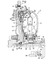
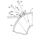
図1は本発明の第1実施例に係るロックアップクラッチ付きトルクコンバータの上半部縦断側面図,図2は図1の2−2線断面図,図3は図1の3部拡大図,図4は図3の4矢視図,図5は本発明の第2実施例を示す,図4との対応図である。
1 is a longitudinal sectional side view of an upper half of a torque converter with a lock-up clutch according to a first embodiment of the present invention, FIG. 2 is a cross-sectional view taken along line 2-2 of FIG. 1, and FIG. 4 is a view taken in the direction of
先ず,図1において,流体伝動装置としてのトルクコンバータTは,ポンプ羽根車2と,それと対置されるタービン羽根車3と,それらの内周部間に配置されるステータ羽根車4とを備え,これら三羽根車2,3,4間に作動オイルによる動力伝達のための循環回路6が画成される。
First, in FIG. 1, a torque converter T as a fluid transmission device includes a
ポンプ羽根車2には,タービン羽根車3の外側面を覆う伝動カバー5が溶接により一体的に連設される。伝動カバー5の外周面には,始動用のリングギヤ7が溶接されており,クランク軸1に結合した駆動板8がこのリングギヤ7にボルト9で固着される。タービン羽根車3のハブ3hと伝動カバー5との間にスラストニードルベアリング36が介裝される。
A
トルクコンバータTの中心部にクランク軸1と同軸上に並ぶ出力軸10が配置され,この出力軸10は,タービン羽根車3のハブ3hにスプライン嵌合されると共に,伝動カバー5のハブ5hの内周面に軸受ブッシュ18を介して回転自在に支承される。出力軸10は図示しない多段変速機の主軸となる。
An
出力軸10の外周には,ステータ羽根車4のハブ4hをフリーホイール11を介して支承する円筒状のステータ軸12が配置され,これら出力軸10及びステータ軸12間には,それらの相対回転を許容する軸受ブッシュ13が介裝される。ステータ軸12の外端部はミッションケース14に回転不能に支持される。
A
ステータ羽根車4のハブ4hと,これに対向するポンプ羽根車2及びタービン羽根車3の各ハブ2h,3hとの間にはスラストニードルベアリング37,37′が介裝される。
またステータ軸12の外周には,ポンプ羽根車2のハブ2hに連設した補機駆動軸20が相対回転可能に配置され,この補機駆動軸20によって,トルクコンバータTに作動オイルを供給するオイルポンプ21が駆動される。
Further, on the outer periphery of the
タービン羽根車3及び伝動カバー5は,それらの間にクラッチ室22を画成して,タービン羽根車3及び伝動カバー5間を直結し得るロックアップクラッチLcを収容する。ロックアップクラッチLcの主体をなすクラッチピストン25は,クラッチ室22をタービン羽根車3側の内側室22aと伝動カバー5側の外側室22bとに区画するようにクラッチ室22に配置される。このクラッチピストン25は,伝動カバー5側に膨出する環状のウェブ25aと,このウェブ25aの外周縁からタービン羽根車3側に屈曲するリム25bとを備えており,ウェブ26には,伝動カバー5の内側面に対向する摩擦ライニング28が付設される。クラッチピストン25は,この摩擦ライニング28を伝動カバー5の内側面に圧接させる接続位置と,その内壁から離間する非接続位置との間を軸方向に移動し得るように,タービン羽根車3のハブ3hの外周面に摺動可能に支承される。
The
図1及び図2に示すように,クラッチ室22には,また,クラッチピストン25及びタービン羽根車3間を緩衝的に連結するトルクダンパDpが配設される。このトルクダンパDpは,クラッチピストン25のリム25bと協働して環状のスプリング収容溝31を画成すべくクラッチピストン25にリベット35で固着される環状のスプリング保持部材30と,スプリング収容溝31に収容されて環状に配列される複数(図示例では3個)のコイル状ダンパスプリング32,32…と,スプリング保持部材30に形成されて各隣接するダンパスプリング32,32間に挿入される複数(ダンパスプリング32と同数)の第1伝動爪33と,タービン羽根車3のシェル3s外周面に溶接され,第1伝動爪33と対向しながら各隣接するダンパスプリング32,32間に挿入される複数(ダンパスプリング32と同数)の第2伝動爪34,34…とで構成される。環状のスプリング保持部材30は,図示例では,各第1伝動爪33の中央部で周方向に分割された複数の扇形部片30a,30a…で構成される。
As shown in FIGS. 1 and 2, the
出力軸10の中心部には,横孔39及びスラストニードルベアリング36を介してクラッチ室22の外側室22bに連通する第1油路40が設けられる。また補機駆動軸20とステータ軸12との間には,スラストニードルベアリング37,37′及びフリーホイール11を介して循環回路6の内周部に連通する第2油路41が画成され,これら第1油路40及び第2油路41は,ロックアップ制御弁42により,オイルポンプ21の吐出側とオイル溜め43とに交互に接続されるようになっている。
A
而して,エンジンのアイドリングないし極低速運転域では,ロックアップ制御弁42は,図1に示すように,第1油路40をオイルポンプ21の吐出側に接続する一方,第2油路41をオイル溜め43に接続するように,図示しない電子制御ユニットにより制御される。したがって,エンジンのクランク軸1の出力トルクが駆動板8,伝動カバー5,ポンプ羽根車2へと伝達して,それを回転駆動し,更にオイルポンプ21をも駆動すると,オイルポンプ21の吐出作動オイルがロックアップ制御弁42から第1油路40,横孔39及びスラストニードルベアリング36,クラッチ室22の外側室22b,内側室22aを順次経て循環回路6に流入し,該回路6を満たした後,スラストニードルベアリング37,37′及びフリーホイール11を順次経て第2油路41に移り,ロックアップ制御弁42からオイル溜め43に還流する。
Thus, in the engine idling or extremely low speed operation region, the
而して,クラッチ室22では,上記のような作動オイルの流れにより外側室22bの方が内側室22aよりも高圧となり,その圧力差によりクラッチピストン25が伝動カバー5の内壁から引き離される方向へ押圧されるので,ロックアップクラッチLcは非接続状態となっており,ポンプ羽根車2及びタービン羽根車3の相対回転を許容している。したがって,クランク軸1からポンプ羽根車2が回転駆動されると,循環回路6を満たしている作動オイルが矢印のように循環回路6を循環することにより,ポンプ羽根車3の回転トルクをタービン羽根車3に伝達し,出力軸10を駆動する。
Thus, in the
このとき,ポンプ羽根車2及びタービン羽根車3間でトルクの増幅作用が生じていれば,それに伴う反力がステータ羽根車4に負担され,ステータ羽根車4は,フリーホイール11のロック作用により固定される。
At this time, if a torque amplifying action is generated between the
トルク増幅作用を終えると,ステータ羽根車4は,これが受けるトルク方向の反転により,フリーホイール11を空転させながらポンプ羽根車2及びタービン羽根車3と共に同一方向へ回転するようになる。
When the torque amplification operation is finished, the
トルクコンバータTがこのようなカップリング状態となったところで,電子制御ユニットによりロックアップ制御弁42を切換える。その結果,オイルポンプ21の吐出作動オイルは,先刻とは反対に,ロックアップ制御弁42から第2油路41を経て循環回路6に流入して,該回路6を満たした後,クラッチ室22の内側室22aに移って,該内側室22aをも満たす。一方,クラッチ室22の外側室22bは,第1油路40及びロックアップ制御弁42を介してオイル溜め43に開放されるので,クラッチ室22では,内側室22aの方が外側室22bよりも高圧となり,クラッチピストン25は,その圧力差により伝動カバー5側に押圧され,摩擦ライニング28を伝動カバー5の内側壁に圧接させ,ロックアップクラッチLcは接続状態となる。すると,クランク軸1からポンプ羽根車2に伝達した回転トルクは,伝動カバー5からクラッチピストン25,複数の第1伝動爪33,33…,ダンパスプリング32,32…及び複数の第2伝動爪34,34…を介してタービン羽根車3に機械的に伝達することになるから,ポンプ羽根車2及びタービン羽根車3は直結の状態となり,クランク軸1の出力トルクを出力軸10に効率良く伝達することができ,燃費の低減を図ることができる。このとき,ポンプ羽根車2及びタービン羽根車3間で急激なトルク変動が生ずると,ダンパスプリング32が第1及び第2伝動爪33,34間で圧縮され,これに伴いポンプ羽根車2及びタービン羽根車3が相対回転することでトルクショックを吸収することができる。
When the torque converter T enters such a coupling state, the
さて,図3及び図4により,第2伝動爪34のタービン羽根車3のシェル3s外周面への,レーザ溶接による接合構造について説明する。
Now, with reference to FIG. 3 and FIG. 4, description will be given of a joining structure by laser welding of the
シェル3sの周方向に沿って配列する複数の第2伝動爪34,34…はそれぞれ分離独立している。各第2伝動爪34は,第1伝動爪33と対向して相隣るダンパスプリング32,32間に挿入される爪部34aと,この爪部34aの根元に一体に連なる矩形の支持部34bとから構成され,全体としてT字形をなしており,鋼板の打ち抜き加工により製作される。その際,支持部34bの,タービン羽根車3の周方向Dに沿う幅Aは爪部34aの幅Bより大きく設定される。この支持部34bがタービン羽根車3のシェル3sの外周面に,レーザ溶接機Wから出射されるレーザビームLにより形成される溶接部40を介して接合される。この溶接部40は,レーザビームLによる溶け込みが支持部34bの外面から前記シェル3sの内周面に達するように,且つシェル3sの周方向に沿う線状に形成される。
The plurality of
而して,溶接時には,レーザ溶接機WからのレーザビームLを第2伝動爪34の支持部34b外面に出射しながら,レーザ溶接機W及びシェル3sを,シェル3sの軸線周りに相対回転することにより,所望長さの線状の溶接部40を容易,確実に形成することができ,支持部34b及びシェル3sに所望の接合強度を与えることができる。しかも線状の正常な溶接部40の溶け込みは,シェル3sの内周面にまで達して,その内面に線状の変色部を形成することになるから,その変色部の有無を目視検査するだけで,溶接部40の良否を簡単,確実に判定することができ,品質の向上に寄与し得る。さらにレーザビームLにより形成される溶接部40への入熱は比較的少ないので,シェル3sの熱歪みを防ぎ,タービン羽根車3の品質の安定化を図ることができる。
Thus, during welding, the laser beam L from the laser welder W is emitted to the outer surface of the
またシェル3sの周方向Dに延びる線状の溶接部40は,互いに間隔をおいて平行に並ぶ複数条,図示例では2条となっており,これら溶接部40の長さCは爪部34aの幅Bより長く設定される。そして各溶接部40の両端は,支持部34bの端縁の手前で終わっている。
Further, the linear welded
而して,シェル3sの周方向Dに沿って爪部34aの幅Bより長く延びる線状の溶接部40を複数条とすることにより,支持部34b及びシェル3sの接合強度を効果的に増強し得ると共に,伝動中,各溶接部40に応力を分散させて,各溶接部40の耐久性を高めることができる。また各溶接部40の両端を支持部34bの端縁の手前で終わらせることで,支持部34bの端縁のレーザビームLによる溶け欠けを防ぎ,その端縁の溶け欠けによる強度低下を防ぐことができ,高トルクの伝達に耐えることができる。
Thus, the joint strength between the
さらに支持部34b及びシェル3sの対向面間には,各溶接部40を囲む間隙gが設けられる。具体的には,支持部34bの,シェル3sに対向する内周面の,複数条の溶接部40,40の配列方向に沿う曲面の曲率半径rが,対応するシェル3sの外周面の曲率半径Rよりも小さく設定される。その結果,レーザ溶接に当たり,支持部34bをシェル3sの外周面に重ねたとき,支持部34bは,溶接部40,40の配列方向に沿う両端縁の2点でシェル3sの外周面に当接し,その他の部分ではシェル3sの外周面との間に間隙gが生じる。そこで複数条の溶接部40,40を形成すべく,上記間隙gの存在する部分においてレーザビームLを支持部34bの外面に出射して,支持部34bの外面からシェル3sの内周面に達する溶け込みを生じさせるとき,その溶融部で発生するガスを周囲の間隙gへ速やかに流出させることができる。特に,第2伝動爪34に耐摩耗性確保のための窒化処理を予め施した場合には,窒化層から発生する窒素ガスを溶接部40周囲の間隙gへスムーズに排出させることができ,したがってガスによるブローホールの発生を防いで,良質の溶接部40を形成することが可能となり,支持部34b及びシェル3sの所望所定通りの接合強度を確保することができる。
Further, a gap g surrounding each welded
複数の第2伝動爪34,34…はそれぞれ分離独立しているので,鋼板から多数の第2伝動爪34を歩留まり良く打ち抜くことができ,しかもトルコンバータTの仕様に応じて,第2伝動爪34の使用個数と,取り付けピッチを自由に設定することにより,各種トルコンバータTに適用可能となり,これらにより製作コストの大幅な低減をもたらすことができる。また複数の第2伝動爪34,34…はタービン羽根車3の外周面に分散配置されることで,それらの間には作動流体の流れを阻害するものを存在させず,したがってロックアップクラッチLcへの作動流体の流れがスムーズとなり,その応答性向上にも寄与し得る。
Since the plurality of
次に,図5に示す本発明の第2実施例について説明する。 Next, a second embodiment of the present invention shown in FIG. 5 will be described.
この第2実施例は,環状配列の複数の第2伝動爪34,34…の支持部34bを,その支持部34bより横幅の狭い連結帯部41を介して相互に一体に連結したもので,その他の構成は,前実施例と同様である。したがって,各第2伝動爪34の支持部34bは,前実施例と同様に,レーザビームLにより形成される線状の複数条の溶接部40,40を介してタービン羽根車3のシェル3sに外面に接合される。尚,図4中,前実施例と対応する部分には同一の参照符号を付して,その説明を省略する。
In the second embodiment, the
この第2実施例によれば,複数の第2伝動爪34,34…の支持部34bは,連結帯部41を介して環状に連結されることになるから,これらのシェル3sへのレーザ溶接に際しては,複数の第2伝動爪34,34…相互の位置決めを行う位置決め治具を使用する必要がなく,溶接作業の能率向上を図ることができる。また連結帯部41の横幅を支持部34bのそれより狭めたので,連結帯部41による重量増を極力抑えることができる。
According to the second embodiment, the
本発明は上記実施例に限定されるものではなく,その要旨を逸脱しない範囲で種々の設計変更が可能である。例えば,本発明は,ステータ羽根車を持たない流体継手にも適用することができる。 The present invention is not limited to the above embodiment, and various design changes can be made without departing from the scope of the invention. For example, the present invention can be applied to a fluid coupling that does not have a stator impeller.
D・・・・・・タービン羽根車の周方向
Dp・・・・・トルクダンパ
L・・・・・・レーザビーム
Lc・・・・・ロックアップクラッチ
T・・・・・・流体伝動装置(トルクコンバータ)
3・・・・・・タービン羽根車
3s・・・・・タービン羽根車のシェル
25・・・・・クラッチピストン
31・・・・・スプリング収容溝
32・・・・・ダンパスプリング
33・・・・・第1伝動爪
34・・・・・第2伝動爪
34a・・・・爪部
34b・・・・支持部
40・・・・・溶接部
D ··· Turbine impeller circumferential direction Dp · · · Torque damper L · · · Laser beam Lc · · · Lock-up clutch T · · · Fluid transmission (torque converter)
3 ....
Claims (5)
前記溶接部(40)を,レーザビーム(L)による溶け込みが前記第2伝動爪(34)の支持部(34b)の外面から前記シェル(3s)の内周面に達するようにして,前記シェル(3s)の周方向に沿った線状に形成したことを特徴とする,ロックアップクラッチ付き流体伝動装置。 A plurality of damper springs (32) are accommodated in an annular spring accommodating groove (31) formed in the clutch piston (25) of the lockup clutch (Lc), and between adjacent damper springs (32). A plurality of first transmission claws (33) to be inserted into the clutch piston (25) are fixed, and a plurality of first transmission claws (33) are inserted between adjacent damper springs (32) while facing the first transmission claw (33). A lock in which the support portion (34b) of the second transmission claw (34) is joined to the outer peripheral surface of the shell (3s) of the turbine impeller (3) via a welded portion (40) formed by a laser beam (L). In fluid transmission with an up clutch,
The welded portion (40) is penetrated by the laser beam (L) so as to reach the inner peripheral surface of the shell (3s) from the outer surface of the support portion (34b) of the second transmission claw (34). A fluid transmission device with a lock-up clutch, wherein the fluid transmission device is formed in a linear shape along the circumferential direction of (3s).
前記線状の溶接部(40)を,互いに間隔を置いて並ぶ複数条形成したことを特徴とする,ロックアップクラッチ付き流体伝動装置。 The fluid transmission device with a lock-up clutch according to claim 1,
A fluid transmission device with a lock-up clutch, wherein the linear welded portion (40) is formed in a plurality of lines arranged at intervals.
各第2伝動爪(34)を,隣接するダンパスプリング(32)間に挿入される爪部(34a)と,この爪部(34a)の根元に一体に連なり,且つタービン羽根車(3)の周方向(D)に沿う幅(A)が爪部(34a)の幅(B)より大きく設定される支持部(34b)とで構成し,この支持部(34b)及び前記シェル(3s)間を,前記周方向(D)に沿って前記爪部(34a)の前記幅(B)よりも長く形成される前記溶接部(40)を介して接合したことを特徴とする,ロックアップクラッチ付き流体伝動装置。 The fluid transmission device with a lock-up clutch according to claim 1 or 2,
Each second transmission claw (34) is integrally connected to a claw portion (34a) inserted between adjacent damper springs (32) and the root of the claw portion (34a), and is connected to the turbine impeller (3). It is comprised with the support part (34b) by which the width | variety (A) along the circumferential direction (D) is set larger than the width | variety (B) of a nail | claw part (34a), and between this support part (34b) and said shell (3s) With a lock-up clutch, characterized by being joined along the circumferential direction (D) via the welded portion (40) formed longer than the width (B) of the claw portion (34a) Fluid transmission device.
線状の前記溶接部(40)を,その両端が前記支持部(34b)の端縁に達しないように形成したことを特徴とする,ロックアップクラッチ付き流体伝動装置。 In the fluid transmission with lock-up clutch according to any one of claims 1 to 3,
The fluid transmission device with a lockup clutch, wherein the linear welded portion (40) is formed so that both ends thereof do not reach the end edge of the support portion (34b).
前記支持部(34b)及びシェル(3s)の対向面間には,前記溶接部(40)を囲む間隙(g)を設けたことを特徴とする,ロックアップクラッチ付き流体伝動装置。
In the fluid transmission with a lock-up clutch according to any one of claims 1 to 4,
A fluid transmission device with a lock-up clutch, characterized in that a gap (g) surrounding the welded portion (40) is provided between the opposing surfaces of the support portion (34b) and the shell (3s).
Priority Applications (5)
| Application Number | Priority Date | Filing Date | Title |
|---|---|---|---|
| JP2004212488A JP4530750B2 (en) | 2004-07-21 | 2004-07-21 | Fluid transmission device with lock-up clutch |
| US11/184,081 US7322454B2 (en) | 2004-07-21 | 2005-07-19 | Fluid transmitting device with lock-up clutch |
| CN200510085057.7A CN1724900B (en) | 2004-07-21 | 2005-07-20 | Fluid transmitting device with lock-up clutch |
| DE602005027150T DE602005027150D1 (en) | 2004-07-21 | 2005-07-21 | Torque converter with lockup clutch |
| EP05254545A EP1619415B1 (en) | 2004-07-21 | 2005-07-21 | Fluid transmission device with lock-up clutch |
Applications Claiming Priority (1)
| Application Number | Priority Date | Filing Date | Title |
|---|---|---|---|
| JP2004212488A JP4530750B2 (en) | 2004-07-21 | 2004-07-21 | Fluid transmission device with lock-up clutch |
Publications (2)
| Publication Number | Publication Date |
|---|---|
| JP2006029531A true JP2006029531A (en) | 2006-02-02 |
| JP4530750B2 JP4530750B2 (en) | 2010-08-25 |
Family
ID=35058962
Family Applications (1)
| Application Number | Title | Priority Date | Filing Date |
|---|---|---|---|
| JP2004212488A Active JP4530750B2 (en) | 2004-07-21 | 2004-07-21 | Fluid transmission device with lock-up clutch |
Country Status (5)
| Country | Link |
|---|---|
| US (1) | US7322454B2 (en) |
| EP (1) | EP1619415B1 (en) |
| JP (1) | JP4530750B2 (en) |
| CN (1) | CN1724900B (en) |
| DE (1) | DE602005027150D1 (en) |
Cited By (1)
| Publication number | Priority date | Publication date | Assignee | Title |
|---|---|---|---|---|
| JP2007298172A (en) * | 2006-05-01 | 2007-11-15 | Luk Lamellen & Kupplungsbau Beteiligungs Kg | Outer plate equipped with arc spring driving tab for torque converter damper |
Families Citing this family (12)
| Publication number | Priority date | Publication date | Assignee | Title |
|---|---|---|---|---|
| WO2007102462A1 (en) * | 2006-03-07 | 2007-09-13 | Daikin Industries, Ltd. | Method of producing compressor, and compressor |
| US7578713B2 (en) | 2006-05-25 | 2009-08-25 | Yutaka Giken Co., Ltd. | Outboard engine system |
| JP4897356B2 (en) * | 2006-05-25 | 2012-03-14 | 株式会社ユタカ技研 | Outboard motor |
| JP4944624B2 (en) | 2007-01-22 | 2012-06-06 | 本田技研工業株式会社 | Fluid transmission device |
| JP5078535B2 (en) * | 2007-10-10 | 2012-11-21 | 株式会社エクセディ | Lock-up device and fluid torque transmission device including the same |
| DE112009002249B4 (en) * | 2008-10-10 | 2017-05-24 | Toyota Jidosha Kabushiki Kaisha | Fluid transfer device |
| JP5728186B2 (en) * | 2010-09-13 | 2015-06-03 | アイシン機工株式会社 | Drive plate and ring gear member of drive plate |
| JP5556551B2 (en) * | 2010-09-30 | 2014-07-23 | アイシン・エィ・ダブリュ株式会社 | Fluid transmission device |
| JP5252126B2 (en) * | 2011-04-18 | 2013-07-31 | トヨタ自動車株式会社 | Manufacturing method and manufacturing apparatus for driving force transmission device for vehicle |
| JP2012237418A (en) * | 2011-05-13 | 2012-12-06 | Yutaka Giken Co Ltd | Hydraulic power transmission with lock-up clutch |
| JP5584249B2 (en) * | 2012-04-10 | 2014-09-03 | 株式会社エクセディ | Torque converter lockup device |
| DE102017124961B3 (en) * | 2017-10-25 | 2018-09-13 | Kleemann Gmbh | Drive system for driving a crusher and method for operating a crusher |
Citations (6)
| Publication number | Priority date | Publication date | Assignee | Title |
|---|---|---|---|---|
| JPH02114185U (en) * | 1989-02-20 | 1990-09-12 | ||
| JPH0544386U (en) * | 1991-11-18 | 1993-06-15 | 日本軽金属株式会社 | Laser welding equipment for connecting surface treated materials |
| JPH0947887A (en) * | 1995-08-04 | 1997-02-18 | Tokai Rubber Ind Ltd | Manufacture of tubular seaming fixture |
| JP2002347659A (en) * | 2001-05-25 | 2002-12-04 | Toyota Motor Corp | Body joint structure |
| JP2003148590A (en) * | 2001-11-12 | 2003-05-21 | Yutaka Giken Co Ltd | Fluid transmission gear with lock-up clutch |
| JP2004511733A (en) * | 2000-10-13 | 2004-04-15 | ツェットエフ ザックス アクチエンゲゼルシャフト | Fluid type clutch device |
Family Cites Families (2)
| Publication number | Priority date | Publication date | Assignee | Title |
|---|---|---|---|---|
| US4942059A (en) * | 1988-09-29 | 1990-07-17 | Westinghouse Electric Corp. | Method for hardfacing metal articles |
| DE19721642C1 (en) * | 1997-05-23 | 1998-07-09 | Mannesmann Sachs Ag | Torsion oscillation damper for lock-up clutch for torque converter |
-
2004
- 2004-07-21 JP JP2004212488A patent/JP4530750B2/en active Active
-
2005
- 2005-07-19 US US11/184,081 patent/US7322454B2/en not_active Expired - Fee Related
- 2005-07-20 CN CN200510085057.7A patent/CN1724900B/en not_active Expired - Fee Related
- 2005-07-21 EP EP05254545A patent/EP1619415B1/en not_active Expired - Fee Related
- 2005-07-21 DE DE602005027150T patent/DE602005027150D1/en active Active
Patent Citations (6)
| Publication number | Priority date | Publication date | Assignee | Title |
|---|---|---|---|---|
| JPH02114185U (en) * | 1989-02-20 | 1990-09-12 | ||
| JPH0544386U (en) * | 1991-11-18 | 1993-06-15 | 日本軽金属株式会社 | Laser welding equipment for connecting surface treated materials |
| JPH0947887A (en) * | 1995-08-04 | 1997-02-18 | Tokai Rubber Ind Ltd | Manufacture of tubular seaming fixture |
| JP2004511733A (en) * | 2000-10-13 | 2004-04-15 | ツェットエフ ザックス アクチエンゲゼルシャフト | Fluid type clutch device |
| JP2002347659A (en) * | 2001-05-25 | 2002-12-04 | Toyota Motor Corp | Body joint structure |
| JP2003148590A (en) * | 2001-11-12 | 2003-05-21 | Yutaka Giken Co Ltd | Fluid transmission gear with lock-up clutch |
Cited By (1)
| Publication number | Priority date | Publication date | Assignee | Title |
|---|---|---|---|---|
| JP2007298172A (en) * | 2006-05-01 | 2007-11-15 | Luk Lamellen & Kupplungsbau Beteiligungs Kg | Outer plate equipped with arc spring driving tab for torque converter damper |
Also Published As
| Publication number | Publication date |
|---|---|
| CN1724900B (en) | 2010-10-13 |
| DE602005027150D1 (en) | 2011-05-12 |
| EP1619415A3 (en) | 2009-07-29 |
| US20060016654A1 (en) | 2006-01-26 |
| JP4530750B2 (en) | 2010-08-25 |
| EP1619415A2 (en) | 2006-01-25 |
| CN1724900A (en) | 2006-01-25 |
| EP1619415B1 (en) | 2011-03-30 |
| US7322454B2 (en) | 2008-01-29 |
Similar Documents
| Publication | Publication Date | Title |
|---|---|---|
| EP1619415B1 (en) | Fluid transmission device with lock-up clutch | |
| EP1621799B1 (en) | Impeller for hydrodynamic clutch and method of manufacturing the same | |
| JP2010255753A (en) | Power transmission device | |
| JP5369297B2 (en) | Double overlap backing plate attachment | |
| JP4498385B2 (en) | Oil pump drive mechanism | |
| JP2008038951A (en) | Fluid type torque transmitting apparatus | |
| US7958724B2 (en) | Torque converter blade | |
| JP2007147034A (en) | Set plate for torque converter | |
| JP5905693B2 (en) | Fluid transmission device for vehicles | |
| US6779639B2 (en) | Fluid transmission system with lock-up clutch | |
| JP2012237418A (en) | Hydraulic power transmission with lock-up clutch | |
| JP4523514B2 (en) | Fluid transmission device with lock-up clutch | |
| JP2003336719A (en) | Impeller for fluid transmitting device | |
| JP2008240801A (en) | Drive plate | |
| JP3971626B2 (en) | Torque converter | |
| JP2003278878A (en) | Torque converter | |
| JP2006038054A (en) | Impeller for fluid transmission device | |
| WO2017149920A1 (en) | Fluid-type rotating impeller | |
| JP2012211707A (en) | Lockup clutch of fluid coupling device | |
| JP2007051752A (en) | Fluid type torque transmission device | |
| JP3971634B2 (en) | Torque converter | |
| JP2003214524A (en) | Torque converter | |
| JP5202229B2 (en) | Lock-up clutch of fluid coupling device | |
| JP3975088B2 (en) | Method for manufacturing pump impeller for fluid transmission device | |
| JP2003247625A (en) | Impeller for fluid transmission device |
Legal Events
| Date | Code | Title | Description |
|---|---|---|---|
| A621 | Written request for application examination |
Free format text: JAPANESE INTERMEDIATE CODE: A621 Effective date: 20070326 |
|
| A977 | Report on retrieval |
Free format text: JAPANESE INTERMEDIATE CODE: A971007 Effective date: 20091022 |
|
| A131 | Notification of reasons for refusal |
Free format text: JAPANESE INTERMEDIATE CODE: A131 Effective date: 20091028 |
|
| A521 | Request for written amendment filed |
Free format text: JAPANESE INTERMEDIATE CODE: A523 Effective date: 20091217 |
|
| TRDD | Decision of grant or rejection written | ||
| A01 | Written decision to grant a patent or to grant a registration (utility model) |
Free format text: JAPANESE INTERMEDIATE CODE: A01 Effective date: 20100526 |
|
| A01 | Written decision to grant a patent or to grant a registration (utility model) |
Free format text: JAPANESE INTERMEDIATE CODE: A01 |
|
| A61 | First payment of annual fees (during grant procedure) |
Free format text: JAPANESE INTERMEDIATE CODE: A61 Effective date: 20100608 |
|
| R150 | Certificate of patent or registration of utility model |
Ref document number: 4530750 Country of ref document: JP Free format text: JAPANESE INTERMEDIATE CODE: R150 Free format text: JAPANESE INTERMEDIATE CODE: R150 |
|
| FPAY | Renewal fee payment (event date is renewal date of database) |
Free format text: PAYMENT UNTIL: 20130618 Year of fee payment: 3 |
|
| FPAY | Renewal fee payment (event date is renewal date of database) |
Free format text: PAYMENT UNTIL: 20130618 Year of fee payment: 3 |
|
| FPAY | Renewal fee payment (event date is renewal date of database) |
Free format text: PAYMENT UNTIL: 20140618 Year of fee payment: 4 |
|
| R250 | Receipt of annual fees |
Free format text: JAPANESE INTERMEDIATE CODE: R250 |
|
| R250 | Receipt of annual fees |
Free format text: JAPANESE INTERMEDIATE CODE: R250 |
|
| R250 | Receipt of annual fees |
Free format text: JAPANESE INTERMEDIATE CODE: R250 |
|
| R250 | Receipt of annual fees |
Free format text: JAPANESE INTERMEDIATE CODE: R250 |
|
| R250 | Receipt of annual fees |
Free format text: JAPANESE INTERMEDIATE CODE: R250 |
|
| R250 | Receipt of annual fees |
Free format text: JAPANESE INTERMEDIATE CODE: R250 |
|
| R250 | Receipt of annual fees |
Free format text: JAPANESE INTERMEDIATE CODE: R250 |
|
| R250 | Receipt of annual fees |
Free format text: JAPANESE INTERMEDIATE CODE: R250 |
|
| R250 | Receipt of annual fees |
Free format text: JAPANESE INTERMEDIATE CODE: R250 |
|
| R250 | Receipt of annual fees |
Free format text: JAPANESE INTERMEDIATE CODE: R250 |
|
| R250 | Receipt of annual fees |
Free format text: JAPANESE INTERMEDIATE CODE: R250 |