JP5369297B2 - Double overlap backing plate attachment - Google Patents
Double overlap backing plate attachment Download PDFInfo
- Publication number
- JP5369297B2 JP5369297B2 JP2008313848A JP2008313848A JP5369297B2 JP 5369297 B2 JP5369297 B2 JP 5369297B2 JP 2008313848 A JP2008313848 A JP 2008313848A JP 2008313848 A JP2008313848 A JP 2008313848A JP 5369297 B2 JP5369297 B2 JP 5369297B2
- Authority
- JP
- Japan
- Prior art keywords
- backing plate
- torque converter
- annular surface
- cover
- torque
- Prior art date
- Legal status (The legal status is an assumption and is not a legal conclusion. Google has not performed a legal analysis and makes no representation as to the accuracy of the status listed.)
- Expired - Fee Related
Links
Images


Classifications
-
- F—MECHANICAL ENGINEERING; LIGHTING; HEATING; WEAPONS; BLASTING
- F16—ENGINEERING ELEMENTS AND UNITS; GENERAL MEASURES FOR PRODUCING AND MAINTAINING EFFECTIVE FUNCTIONING OF MACHINES OR INSTALLATIONS; THERMAL INSULATION IN GENERAL
- F16H—GEARING
- F16H45/00—Combinations of fluid gearings for conveying rotary motion with couplings or clutches
- F16H45/02—Combinations of fluid gearings for conveying rotary motion with couplings or clutches with mechanical clutches for bridging a fluid gearing of the hydrokinetic type
- F16H2045/021—Combinations of fluid gearings for conveying rotary motion with couplings or clutches with mechanical clutches for bridging a fluid gearing of the hydrokinetic type three chamber system, i.e. comprising a separated, closed chamber specially adapted for actuating a lock-up clutch
-
- F—MECHANICAL ENGINEERING; LIGHTING; HEATING; WEAPONS; BLASTING
- F16—ENGINEERING ELEMENTS AND UNITS; GENERAL MEASURES FOR PRODUCING AND MAINTAINING EFFECTIVE FUNCTIONING OF MACHINES OR INSTALLATIONS; THERMAL INSULATION IN GENERAL
- F16H—GEARING
- F16H45/00—Combinations of fluid gearings for conveying rotary motion with couplings or clutches
- F16H45/02—Combinations of fluid gearings for conveying rotary motion with couplings or clutches with mechanical clutches for bridging a fluid gearing of the hydrokinetic type
- F16H2045/0221—Combinations of fluid gearings for conveying rotary motion with couplings or clutches with mechanical clutches for bridging a fluid gearing of the hydrokinetic type with damping means
- F16H2045/0247—Combinations of fluid gearings for conveying rotary motion with couplings or clutches with mechanical clutches for bridging a fluid gearing of the hydrokinetic type with damping means having a turbine with hydrodynamic damping means
-
- F—MECHANICAL ENGINEERING; LIGHTING; HEATING; WEAPONS; BLASTING
- F16—ENGINEERING ELEMENTS AND UNITS; GENERAL MEASURES FOR PRODUCING AND MAINTAINING EFFECTIVE FUNCTIONING OF MACHINES OR INSTALLATIONS; THERMAL INSULATION IN GENERAL
- F16H—GEARING
- F16H45/00—Combinations of fluid gearings for conveying rotary motion with couplings or clutches
- F16H45/02—Combinations of fluid gearings for conveying rotary motion with couplings or clutches with mechanical clutches for bridging a fluid gearing of the hydrokinetic type
- F16H2045/0273—Combinations of fluid gearings for conveying rotary motion with couplings or clutches with mechanical clutches for bridging a fluid gearing of the hydrokinetic type characterised by the type of the friction surface of the lock-up clutch
- F16H2045/0284—Multiple disk type lock-up clutch
Description
本発明は概してトルクコンバータに関する。特に、本発明は、内部トルク伝達コンポーネントのためのトルクコンバータハウジングアタッチメントに関する。 The present invention generally relates to torque converters. In particular, the present invention relates to a torque converter housing attachment for an internal torque transmitting component.
トルクコンバータが、カバー及びインペラシェル含むハウジングを有することは、トルクコンバータの分野において周知である。トルクをハウジングから、係合するコンポーネント、例えばクラッチプレートに伝達するために、ハウジングに定置に取り付けられた内部コンポーネントを有することがトルクコンバータクラッチ設計の技術分野においても知られている。1つの特定の設計において、内部コンポーネントは、スプライン係合等の機械的ファスナを介して、又は金属不活性ガス(MIG)溶接、タングステン不活性ガス(TIG)溶接、又はレーザ溶接、又はこれらの組み合わせを介してハウジングに取り付けられた、トルクコンバータの回転軸線に対して直交方向の環状のプレートである。ハウジングが回転すると、ハウジングはトルクをプレートに伝達する。プレート自体はトルクを、概して環状クラッチプレートの積層である係合するコンポーネントに、これらの間の1つ又は2つ以上の摩擦係合を介して伝達する。あいにく、このタイプの従来のトルクコンバータクラッチ設計は多くの欠点を有する。 It is well known in the field of torque converters that a torque converter has a housing that includes a cover and an impeller shell. It is also known in the art of torque converter clutch design to have an internal component that is fixedly mounted to the housing to transmit torque from the housing to an engaging component, such as a clutch plate. In one particular design, the internal components can be through mechanical fasteners such as spline engagement, or metal inert gas (MIG) welding, tungsten inert gas (TIG) welding, or laser welding, or combinations thereof. It is the cyclic | annular plate of the orthogonal direction with respect to the rotating shaft line of the torque converter attached to the housing via. As the housing rotates, the housing transmits torque to the plate. The plate itself transmits torque to engaging components, which are generally a stack of annular clutch plates, via one or more frictional engagements between them. Unfortunately, this type of conventional torque converter clutch design has many drawbacks.
例えば、米国特許第6688441号明細書(Arhab)は、トルクを係合するコンポーネントに伝達するための、トルクコンバータのハウジングに定置に取り付けられた環状プレートを備えたトルクコンバータを開示している。Arhabは多くの実施形態を開示しており、それぞれの実施形態は1つ又は2つ以上の欠点を有する。Arhab特許の図1はトルクコンバータハウジングを示しており、この場合、前側シェル(カバー)の環状前側軸方向スカートが環状トルク伝達プレートコンポーネントを超えて延びており、この環状トルク伝達プレートコンポーネントに前側シェルは溶接シームを介して取り付けられている。前側シェルは、後側(インペラ)シェルの環状後側軸方向スカートと重なり合っており、この環状後側軸方向スカートにも前側シェルは溶接を介して取り付けられている。この実施形態の1つの欠点は、特に前側シェル(カバー)がスタンピングされた部材であるならば、前側シェル(カバー)を製造するための費用が高い。プレート及びインペラシェルの両方に重なり合うように十分に長い軸方向スカートを備えたカバーは、過剰な量の原材料を使用し、これは費用が高く、トルクコンバータ全体を過剰に重くする。さらに、概してそうであるように、カバーがスタンピングされた部材であるならば、長い軸方向スカートはしばしば製造中に、技術分野において"ポテトチッピング"として口語的に知られているように、スタンピングに対するカバー材料の抵抗により不意に変形させられる。さらに、トルク伝達プレートコンポーネントにハウジングを取り付けるために使用される様々なタイプの溶接はしばしばプレートコンポーネントの変形を生ぜしめる。さらに、カバーがインペラシェルに重なり合っている又はその逆である設計において、トルクコンバータの全体的な半径方向パッケージが過剰である。 For example, US Pat. No. 6,688,441 (Arhab) discloses a torque converter with an annular plate fixedly attached to a torque converter housing for transmitting torque to an engaging component. Arhab discloses many embodiments, each having one or more disadvantages. FIG. 1 of the Arhab patent shows a torque converter housing, in which an annular front axial skirt of the front shell (cover) extends beyond the annular torque transmission plate component, which is connected to the front shell. Are attached via weld seams. The front shell overlaps the annular rear axial skirt of the rear (impeller) shell, and the front shell is also attached to the annular rear axial skirt via welding. One disadvantage of this embodiment is the high cost of manufacturing the front shell (cover), especially if the front shell (cover) is a stamped member. A cover with an axial skirt that is long enough to overlap both the plate and the impeller shell uses an excessive amount of raw material, which is expensive and makes the entire torque converter excessively heavy. Further, as is generally the case, if the cover is a stamped member, long axial skirts are often produced during stamping, as known colloquially in the art as “potato chipping”. It is deformed unexpectedly by the resistance of the cover material. Moreover, the various types of welds used to attach the housing to the torque transmitting plate component often result in deformation of the plate component. Furthermore, the overall radial package of the torque converter is excessive in designs where the cover overlaps the impeller shell or vice versa.
Arhab特許の図5,7及び9は、ハウジングが、機械的に、例えばスプライン係合又は保持リングを介してトルク伝達プレートに取り付けられている実施形態を示している。機械的なファスナは本質的に作動中にがたつく傾向がある。なぜならば、コンポーネントは、よく機械加工されているが、互いに固定して取り付けられておらず、作動中に振動及び/又は互いに衝突する。 FIGS. 5, 7 and 9 of the Arhab patent show an embodiment in which the housing is mechanically attached to the torque transmission plate, for example via a spline engagement or retaining ring. Mechanical fasteners inherently tend to rattle during operation. Because components are well machined, they are not fixedly attached to each other and vibrate and / or collide with each other during operation.
Arhab特許の図11及び図16は、カバーがトルクコンバータの内部においてトルク伝達プレートに溶接されている実施形態を示している。トルクコンバータの内部における溶接は、トルクコンバータ内の望ましくない汚染を生じ、これはトルクコンバータの運転に悪影響を及ぼす。
したがって、ハウジングが内部トルク伝達プレートに固定して取り付けられており、上述の欠点を有さないトルクコンバータが長い間必要とされている。特に、より安価に製造され、溶接によってより変形しないより安定したトルク伝達プレートコンポーネントを形成し、より軽量で、減じられた全体的半径方向パッケージを有し、がたつかず、コンポーネントを主に外部において溶接することにより内部の汚染の危険性を低減する、このタイプのトルクコンバータが長い間必要とされている。 Accordingly, there has long been a need for a torque converter in which the housing is fixedly attached to the internal torque transmission plate and does not have the disadvantages described above. In particular, it is cheaper to manufacture, forms a more stable torque transmission plate component that is less deformed by welding, has a lighter, reduced overall radial package, is not rattle, and the component is mainly external There has long been a need for this type of torque converter that reduces the risk of internal contamination by welding.
本発明は、横方向回転軸線が設けられており、外径と、内径と、軸方向内側環状面とを有するカバーが設けられており、外径と、内径と、軸方向内側環状面とを有するインペラシェルが設けられており、外径と、軸方向外側環状面とを有する環状バッキングプレートが設けられており、カバーと、インペラシェルと、バッキングプレートとが、回転軸線を中心として回転するように操作的に配置されており、バッキングプレートが回転軸線に対して直交方向であり、カバーの外径及び内径がそれぞれインペラシェルの外径及び内径に実質的に等しく、カバーの軸方向内側環状面とインペラシェルの軸方向内側環状面とが、バッキングプレートの軸方向外側環状面に固定して取り付けられている、トルクコンバータである。本発明の好適な実施形態において、環状バッキングプレートは、この環状バッキングプレートの外径から延びた環状壁部を有している。 The present invention is provided with a lateral rotation axis, and is provided with a cover having an outer diameter, an inner diameter, and an axial inner annular surface. The outer diameter, the inner diameter, and the axial inner annular surface are An impeller shell is provided, an annular backing plate having an outer diameter and an axially outer annular surface is provided, and the cover, the impeller shell, and the backing plate are rotated about the rotation axis. , The backing plate is perpendicular to the rotational axis, the outer diameter and inner diameter of the cover are substantially equal to the outer diameter and inner diameter of the impeller shell, respectively, and the axially inner annular surface of the cover And the axially inner annular surface of the impeller shell are fixedly attached to the axially outer annular surface of the backing plate. In a preferred embodiment of the present invention, the annular backing plate has an annular wall extending from the outer diameter of the annular backing plate.
運転中、カバー及びインペラシェルはトルクを環状バッキングプレートに伝達する。好適な実施形態において、トルクコンバータはさらに少なくとも1つの係合するコンポーネント、好適には回転軸線に対して実質的に直交する環状プレート、を有しており、バッキングプレートはさらに、回転軸線に対して実質的に直交する環状面を有している。係合するコンポーネントはバッキングプレートの環状面と摩擦係合している。運転中、バッキングプレートはトルクを係合するコンポーネントに伝達する。好適な実施形態において、トルクコンバータは、回転軸線に沿って連続して配置された係合するコンポーネントのセットを有しており、それぞれのコンポーネントは、隣接するコンポーネントと摩擦係合している。運転中、ハウジング、すなわちカバー及びインペラシェルはトルクをバッキングプレートに伝達し、バッキングプレートはトルクを、摩擦係合を介して、次々に、係合するコンポーネントのセットに伝達する。 During operation, the cover and impeller shell transmit torque to the annular backing plate. In a preferred embodiment, the torque converter further comprises at least one engaging component, preferably an annular plate substantially orthogonal to the rotational axis, and the backing plate further comprises a rotational axis. It has an annular surface that is substantially orthogonal. The engaging component is in frictional engagement with the annular surface of the backing plate. During operation, the backing plate transmits torque to the engaging components. In a preferred embodiment, the torque converter has a set of engaging components arranged sequentially along the axis of rotation, each component being in frictional engagement with an adjacent component. During operation, the housing, i.e. the cover and the impeller shell, transmits torque to the backing plate, which in turn transmits the torque via frictional engagement to the set of components to engage.
本発明の目的は、従来の設計よりも安価に製造されかつ組み立てられる、上述のタイプのトルクコンバータ設計を提供することである。 It is an object of the present invention to provide a torque converter design of the type described above that is manufactured and assembled cheaper than conventional designs.
本発明の別の目的は、軽量で、減じられた全体的半径方向パッケージを有し、がたつかず、コンポーネントを主に外部において溶接することによって内部汚染の危険性を低減する、このタイプのトルクコンバータを提供することである。 Another object of the present invention is this type of torque that is lightweight, has a reduced overall radial package, does not rattle, and reduces the risk of internal contamination by welding components primarily externally. Is to provide a converter.
本発明のこれらの目的及び利点並びにその他の目的及び利点は、発明の好適な実施形態の以下の説明及び添付の図面及び請求の範囲から容易に認識可能であろう。 These and other objects and advantages of the present invention will be readily apparent from the following description of preferred embodiments of the invention and the accompanying drawings and claims.
本発明の性質及び態様はここで、添付の図面に関連した発明の以下の詳細な説明により詳細に説明される。 The nature and aspects of the present invention will now be described in detail by the following detailed description of the invention with reference to the accompanying drawings.
最初に、異なる図面における同じ図面番号は、発明の同じ、又は機能的に類似の構造的なエレメントを表示していることが認められるべきである。本発明は、好適な態様であると現時点で考えられているものに関して説明されるが、請求の範囲に記載された発明は、開示された態様に限定されないものと理解されるべきである。 Initially, it should be appreciated that the same drawing number in different drawings represents the same or functionally similar structural element of the invention. Although the invention has been described with reference to what are presently considered to be preferred embodiments, it is to be understood that the invention as claimed should not be limited to the disclosed embodiments.
さらに、本発明は、説明された特定の方法、材料及び変更に限定されず、それ自体がもちろん変更されてよいことが理解される。また、ここで使用される用語は、特定の態様を説明することだけを目的としており、本発明の範囲を限定しようとするのではなく、本発明の範囲は添付の請求の範囲によってのみ限定される。 Further, it is understood that the invention is not limited to the specific methods, materials, and modifications described and may, of course, vary. Also, the terminology used herein is for the purpose of describing particular embodiments only and is not intended to limit the scope of the invention, which is limited only by the scope of the appended claims. The
そうでないことが定義されない限り、ここで使用される全ての技術用語及び科学用語は、本発明が属する技術の分野における当業者に一般的に理解されるのと同じ意味を有する。ここに説明されたものと類似の又は均等のあらゆる方法、装置又は材料は、発明の実施又は試験において使用されることができるが、好適な方法、装置及び材料がここで説明される。 Unless defined otherwise, all technical and scientific terms used herein have the same meaning as commonly understood by one of ordinary skill in the art to which this invention belongs. Although any methods, devices or materials similar or equivalent to those described herein can be used in the practice or testing of the invention, the preferred methods, devices and materials are now described.
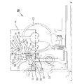
図1は、本発明のトルクコンバータ10の部分的な断面図である。トルクコンバータ10は、コンバータハウジング15と、バッキングプレート40とを有しており、コンバータハウジング15は、カバー20と、インペラシェル30とを有しており、これらは全て、横方向軸線X−X′を中心として回転するように操作的に配置されている。トルクコンバータ10はさらにピストンプレート70を有している。以後、方向の用語"前"は、Xに向かう方向を表し、方向の用語"後"は、X′に向かう方向を表す。
FIG. 1 is a partial cross-sectional view of a
カバー20は、軸線X−X′に対して実質的に直交する前壁23と、軸方向で後方に向けられた環状壁部22とを有している。環状壁部22は、環状縁部24と軸方向内側環状面25とを有している。カバー20はさらに、以下に詳細に説明される、外径及び内径を有している。本発明の1つの実施形態において、カバーは、スタンピングされた金属から形成されている。
The
インペラシェル30は、軸線X−X′に対して実質的に直交する、セミトロイダルのエンベロープ33と、軸方向で前方に向けられた環状スカート31とを有している。環状スカート31は環状縁部34と軸方向内側環状面35とを有している。インペラシェル30はさらに、以下に詳細に説明される、外径及び内径を有している。
The
バッキングプレート40は、軸線X−X′に対して実質的に直交しかつ、以下に詳細に説明される外径を有する環状プレート41と、軸方向でプレート41の外径から後方に向かって延びた環状壁部43とを有しており、環状壁部43は軸方向外側環状面45を有している。
The
図1Aは、図1に示された領域1Aの拡大図である。この図に示されているように、壁部22の軸方向内側環状面25の一部とスカート31の軸方向内側環状面35の一部とが壁部43の軸方向外側環状面45に接触するように、壁部22及びスカート31の両方がバッキングプレート40に重なり合っている。壁部22及びスカート31はバッキングプレート40の軸方向外側環状面45に固定して取り付けられている。
FIG. 1A is an enlarged view of a
本発明の好適な実施形態において、コンバータハウジング15は、トルクをバッキングプレート40に伝達するように操作的に配置されている。バッキングプレート40はさらに半径方向環状面58を有している。好適な実施形態において、バッキングプレート40は、係合するコンポーネント50のセットにトルクを伝達するように操作的に配置されており、係合するコンポーネントは、出力プレート54等の少なくとも1つの係合するコンポーネントを含み、さらに出力プレート52を含むことができる。出力プレート54及び52は、トルクを車両のトランスミッションに伝達するように操作的に配置されている。バッキングプレート40は、半径方向環状面58と出力プレート54との間の摩擦係合を介してトルクを出力プレート54に伝達する。1つの実施形態において、係合するコンポーネント54は環状プレートを有する。好適な実施形態において、係合するコンポーネント50のセットは、一連の係合するコンポーネント54,53,52及び51を有しており、これらのコンポーネントは、それぞれ摩擦係合57,56及び55を介して次々にトルクを伝達するように操作的に配置されている。係合するコンポーネント51及び53は、車両のエンジンからトルクを受け取るように操作的に配置されている。例えば、係合するコンポーネント51は、板ばねアタッチメント等の機械的係合を介してカバー20に取り付けられることができる。好適な実施形態において、係合するコンポーネント50のセットは、クラッチプレートの積層を含む。
In the preferred embodiment of the present invention, the
好適な実施形態において、トルクコンバータ10は、部分的に、カバー20内に、係合するコンポーネント50のセットの積層を介して組み立てられる。次いで、バッキングプレート40は、係合するコンポーネント50のセットに対してしっかりと押し付けられ、次いで適切なリフト量に持ち上げられ、所定の位置にタック溶接される。次いで、トルクコンバータ10の残りが組み立てられ、インペラシェル30が、コンバータ軸揺れを設定するために持ち上げられ、バッキングプレートにタックされる。次いで、トルクコンバータ10は、金属不活性ガス溶接によってシールされ、金属不活性ガス溶接は、カバー20及びインペラシェル30をバッキングプレート40の軸方向外側環状面45に固定して取り付ける。好適な実施形態において、図示のように、これは、環状縁部24及び34のそれぞれと、軸方向外側面との間の溶接27及び37を介して達成される。
In the preferred embodiment, the
図2は、明瞭にするために内部コンポーネントのほとんどを備えないトルクコンバータ10の部分的断面図を示している。上述のように、カバー20及びインペラシェル30はそれぞれ外径及び内径を有しており、バッキングプレート40は外径を有している。線O−O′及びI−I′は両方とも軸線X−X′に対して平行である。線O−O′は、カバー20及びインペラシェル30の外径に対してほぼ接線方向に延びている。しかしながら、カバー20及びインペラシェル30の外径は同じである必要はない。幾つかの実施形態において、インペラシェル30は、カバー20よりも薄い材料からスタンピングされている。なぜならば、インペラシェル30は、トロイダル面にろう接されるブレード(図示せず)から強度を得るからである。線I−I′は、カバー20の内径及び軸方向内側環状面25と、インペラシェル30の内径及び軸方向内側環状面35と、バッキングプレート40の外径及び軸方向外側環状面45とに対して接線方向に延びている。線20a,30a及び40aは、軸線X−X′から、カバー20、インペラシェル30及びバッキングプレート40それぞれの外径までの半径方向距離を表している。図示のように、線20a及び30aは実質的に同じ長さであり、カバー20及びインペラシェル30の外径が実質的に等しいことを表している。線20b及び30bは、軸線X−X′からカバー20及びインペラシェル30のそれぞれの内径までの半径方向距離を表している。図示のように、線20b,30b及び40aは実質的に等しい長さであり、カバー20及びインペラシェル30の内径は、互いに及びバッキングプレート40の外径に実質的に等しい。
FIG. 2 shows a partial cross-sectional view of the
したがって、本発明の目的が効率的に得られることが分かるが、発明への変更は当業者に容易に明らかであるべきであり、これらの変更は、請求の範囲に記載された発明の精神及び範囲に含まれることが意図される。前記説明は本発明の例示であり、制限するものとして考えられるべきでなはないことも理解される。したがって、本発明のその他の実施形態は、本発明の精神及び範囲から逸脱することなしに可能である。 Thus, while it will be appreciated that the objectives of the invention can be obtained efficiently, modifications to the invention should be readily apparent to those skilled in the art, and these modifications are within the spirit and scope of the claimed invention. It is intended to be included in the range. It is also understood that the foregoing description is exemplary of the present invention and should not be considered as limiting. Accordingly, other embodiments of the invention are possible without departing from the spirit and scope of the invention.
10 トルクコンバータ、 15 コンバータハウジング、 20 カバー、 22 環状壁部、 23 前壁、 24 環状縁部、 25 軸方向内側環状面、 30 インペラシェル、 31 環状スカート、 33 エンベロープ、 34 環状縁部、 35 軸方向内側環状面、 40 バッキングプレート、 41 環状プレート、 43 環状壁部、 45 軸方向外側環状面、 50 係合するコンポーネント、 52 出力プレート、 54 出力プレート、 55,56,57 摩擦係合、 58 半径方向環状面、 70 ピストンプレート 10 torque converter, 15 converter housing, 20 cover, 22 annular wall, 23 front wall, 24 annular edge, 25 axial inner annular surface, 30 impeller shell, 31 annular skirt, 33 envelope, 34 annular edge, 35 axis Inner annular surface, 40 backing plate, 41 annular plate, 43 annular wall, 45 axial outer annular surface, 50 engaging components, 52 output plate, 54 output plate, 55, 56, 57 friction engagement, 58 radius Directional annular surface, 70 piston plate
Claims (10)
横方向の回転軸線が設けられており、
内径と、軸方向内側環状面とを有するカバーが設けられており、
内径と、軸方向内側環状面とを有するインペラシェルが設けられており、
外径と、円周と、軸方向外側環状面とを有する環状のバッキングプレートが設けられており、カバーと、インペラシェルと、バッキングプレートとが、回転軸線を中心として回転するように操作的に配置されており、バッキングプレートが、回転軸線に対して実質的に直交しており、カバーの内径が実質的にインペラシェルの内径と等しく、カバーの軸方向内側環状面とインペラシェルの軸方向内側環状面とが、バッキングプレートの軸方向外側環状面に固定して取り付けられていることを特徴とする、トルクコンバータ。 In the torque converter,
A horizontal axis of rotation is provided,
A cover having an inner diameter and an axially inner annular surface is provided;
An impeller shell having an inner diameter and an axially inner annular surface is provided;
An annular backing plate having an outer diameter, a circumference, and an axially outer annular surface is provided, and the cover, the impeller shell, and the backing plate are operatively rotated about the rotation axis. Disposed, the backing plate is substantially perpendicular to the axis of rotation, the inner diameter of the cover is substantially equal to the inner diameter of the impeller shell, and the axially inner annular surface of the cover and the axially inner side of the impeller shell The torque converter, wherein the annular surface is fixedly attached to the axially outer annular surface of the backing plate.
Applications Claiming Priority (2)
| Application Number | Priority Date | Filing Date | Title |
|---|---|---|---|
| US741207P | 2007-12-12 | 2007-12-12 | |
| US61/007,412 | 2007-12-12 |
Publications (3)
| Publication Number | Publication Date |
|---|---|
| JP2009144921A JP2009144921A (en) | 2009-07-02 |
| JP2009144921A5 JP2009144921A5 (en) | 2012-02-02 |
| JP5369297B2 true JP5369297B2 (en) | 2013-12-18 |
Family
ID=40680292
Family Applications (1)
| Application Number | Title | Priority Date | Filing Date |
|---|---|---|---|
| JP2008313848A Expired - Fee Related JP5369297B2 (en) | 2007-12-12 | 2008-12-10 | Double overlap backing plate attachment |
Country Status (3)
| Country | Link |
|---|---|
| US (1) | US7878313B2 (en) |
| JP (1) | JP5369297B2 (en) |
| DE (1) | DE102008060577A1 (en) |
Families Citing this family (7)
| Publication number | Priority date | Publication date | Assignee | Title |
|---|---|---|---|---|
| DE102008020684A1 (en) * | 2007-05-09 | 2008-11-13 | Luk Lamellen Und Kupplungsbau Beteiligungs Kg | Torque converter with anti-rattle and cooling flow arrangement |
| DE102007061242B4 (en) * | 2007-12-19 | 2021-05-20 | Zf Friedrichshafen Ag | Coupling arrangement with a coupling device |
| WO2014174563A1 (en) * | 2013-04-22 | 2014-10-30 | トヨタ自動車株式会社 | Fluid transmission device |
| DE102014207527A1 (en) | 2013-05-03 | 2014-11-06 | Schaeffler Technologies Gmbh & Co. Kg | friction clutch |
| US9845854B2 (en) * | 2014-10-23 | 2017-12-19 | Valeo Embrayages | Hydrokinetic torque coupling device having turbine-piston lock-up clutch, and related methods |
| EP3259503B1 (en) * | 2015-02-17 | 2021-06-16 | Allison Transmission, Inc. | Torque converter lockup clutch backing plate |
| US11649883B1 (en) * | 2022-04-05 | 2023-05-16 | Schaeffler Technologies AG & Co. KG | Connection interface for reaction plate in torque converter |
Family Cites Families (9)
| Publication number | Priority date | Publication date | Assignee | Title |
|---|---|---|---|---|
| JPH03115247U (en) * | 1990-03-09 | 1991-11-28 | ||
| DE19905625A1 (en) | 1998-02-17 | 1999-08-19 | Luk Getriebe Systeme Gmbh | Hydraulic power transmission system using polymer coated housing rear |
| JP2000179644A (en) * | 1998-12-18 | 2000-06-27 | Toyota Motor Corp | Driving device for vehicle |
| FR2797014B1 (en) * | 1999-07-27 | 2001-11-02 | Valeo | HYDROKINETIC COUPLING APPARATUS |
| JP2002054715A (en) * | 2000-08-09 | 2002-02-20 | Yutaka Giken Co Ltd | Casing for hydraulic transmission |
| DE10342898A1 (en) * | 2003-09-17 | 2005-04-14 | Zf Friedrichshafen Ag | Hydrodynamic torque converter |
| WO2007128259A1 (en) * | 2006-05-04 | 2007-11-15 | Luk Lamellen Und Kupplungsbau Beteiligungs Kg | Hydrodynamic torque converter with coupling spring device for the piston |
| WO2008000212A2 (en) * | 2006-06-28 | 2008-01-03 | Luk Lamellen Und Kupplungsbau Beteiligungs Kg | Torque converter, and method for converting torque in a motor vehicle |
| DE102008020684A1 (en) * | 2007-05-09 | 2008-11-13 | Luk Lamellen Und Kupplungsbau Beteiligungs Kg | Torque converter with anti-rattle and cooling flow arrangement |
-
2008
- 2008-12-04 DE DE102008060577A patent/DE102008060577A1/en not_active Withdrawn
- 2008-12-08 US US12/315,888 patent/US7878313B2/en not_active Expired - Fee Related
- 2008-12-10 JP JP2008313848A patent/JP5369297B2/en not_active Expired - Fee Related
Also Published As
| Publication number | Publication date |
|---|---|
| US20090152067A1 (en) | 2009-06-18 |
| JP2009144921A (en) | 2009-07-02 |
| DE102008060577A1 (en) | 2009-06-18 |
| US7878313B2 (en) | 2011-02-01 |
Similar Documents
| Publication | Publication Date | Title |
|---|---|---|
| JP5369297B2 (en) | Double overlap backing plate attachment | |
| JP4715161B2 (en) | Planetary gear unit | |
| US10060482B2 (en) | Joint-site design comprising a hub and a shaft or a gear being friction welded | |
| US20160356372A1 (en) | Differential assembly with single weld joint connecting two-piece differential case and ring gear | |
| US20180106350A1 (en) | Extruded protrusion laser welded seal plate | |
| JP6361617B2 (en) | Torsional vibration reduction device | |
| JP2009121675A (en) | Hydrodynamic coupling device having friction disc held by rotating linking element of turbine wheel with damper plate | |
| JP4530750B2 (en) | Fluid transmission device with lock-up clutch | |
| US20160305523A1 (en) | Hydrokinetic torque converter with crimped blades and method for making the same | |
| JP5905693B2 (en) | Fluid transmission device for vehicles | |
| US7997072B2 (en) | Stamped pilot welded to a cover | |
| JP2018522178A (en) | Disc assembly for multi-plate clutch | |
| US20030121743A1 (en) | Fluid-type torque transmission device with lockup clutch | |
| US20150152949A1 (en) | Piloting sleeve for centering transmission input shaft | |
| JP2009150496A (en) | Belt-type continuously variable transmission and its pulley | |
| JP2019086029A (en) | Torsional vibration reduction device | |
| US7654172B2 (en) | Torque transmission device | |
| US20090056323A1 (en) | Method for forming a rim on a torque converter | |
| JP2020133820A (en) | Torque converter | |
| US20190011030A1 (en) | Fluid-type rotary bladed wheel | |
| US11946534B1 (en) | Closure for micro torque converter | |
| JP2012211707A (en) | Lockup clutch of fluid coupling device | |
| JP2002054715A (en) | Casing for hydraulic transmission | |
| JP4523514B2 (en) | Fluid transmission device with lock-up clutch | |
| JP2009036376A (en) | Torque converter with piston centered on clutch plate |
Legal Events
| Date | Code | Title | Description |
|---|---|---|---|
| RD04 | Notification of resignation of power of attorney |
Free format text: JAPANESE INTERMEDIATE CODE: A7424 Effective date: 20101227 |
|
| RD04 | Notification of resignation of power of attorney |
Free format text: JAPANESE INTERMEDIATE CODE: A7424 Effective date: 20101228 |
|
| A521 | Written amendment |
Free format text: JAPANESE INTERMEDIATE CODE: A523 Effective date: 20111209 |
|
| A621 | Written request for application examination |
Free format text: JAPANESE INTERMEDIATE CODE: A621 Effective date: 20111209 |
|
| A977 | Report on retrieval |
Free format text: JAPANESE INTERMEDIATE CODE: A971007 Effective date: 20130620 |
|
| TRDD | Decision of grant or rejection written | ||
| A01 | Written decision to grant a patent or to grant a registration (utility model) |
Free format text: JAPANESE INTERMEDIATE CODE: A01 Effective date: 20130708 |
|
| A601 | Written request for extension of time |
Free format text: JAPANESE INTERMEDIATE CODE: A601 Effective date: 20130807 |
|
| A602 | Written permission of extension of time |
Free format text: JAPANESE INTERMEDIATE CODE: A602 Effective date: 20130813 |
|
| A711 | Notification of change in applicant |
Free format text: JAPANESE INTERMEDIATE CODE: A711 Effective date: 20130826 |
|
| A61 | First payment of annual fees (during grant procedure) |
Free format text: JAPANESE INTERMEDIATE CODE: A61 Effective date: 20130827 |
|
| A521 | Written amendment |
Free format text: JAPANESE INTERMEDIATE CODE: A821 Effective date: 20130826 |
|
| R150 | Certificate of patent or registration of utility model |
Ref document number: 5369297 Country of ref document: JP Free format text: JAPANESE INTERMEDIATE CODE: R150 Free format text: JAPANESE INTERMEDIATE CODE: R150 |
|
| S111 | Request for change of ownership or part of ownership |
Free format text: JAPANESE INTERMEDIATE CODE: R313111 |
|
| R350 | Written notification of registration of transfer |
Free format text: JAPANESE INTERMEDIATE CODE: R350 |
|
| R250 | Receipt of annual fees |
Free format text: JAPANESE INTERMEDIATE CODE: R250 |
|
| R250 | Receipt of annual fees |
Free format text: JAPANESE INTERMEDIATE CODE: R250 |
|
| R250 | Receipt of annual fees |
Free format text: JAPANESE INTERMEDIATE CODE: R250 |
|
| LAPS | Cancellation because of no payment of annual fees |