JP2006015169A - Game machine - Google Patents
Game machine Download PDFInfo
- Publication number
- JP2006015169A JP2006015169A JP2005278727A JP2005278727A JP2006015169A JP 2006015169 A JP2006015169 A JP 2006015169A JP 2005278727 A JP2005278727 A JP 2005278727A JP 2005278727 A JP2005278727 A JP 2005278727A JP 2006015169 A JP2006015169 A JP 2006015169A
- Authority
- JP
- Japan
- Prior art keywords
- stop
- reel
- winning
- control
- stop display
- Prior art date
- Legal status (The legal status is an assumption and is not a legal conclusion. Google has not performed a legal analysis and makes no representation as to the accuracy of the status listed.)
- Withdrawn
Links
Images


Abstract
Description
本発明は、入賞態様に応じた図柄を予め定めた個数の範囲内で引き込んで停止表示する機能、およびこの停止表示制御を中断する機能を持った遊技機に関するものである。 The present invention relates to a gaming machine having a function of drawing a symbol corresponding to a winning mode within a predetermined number of ranges and displaying it in a stopped state, and a function of interrupting the stop display control.
従来、この種の遊技機としては例えばCT(チャレンジ・タイム)機と呼ばれるスロットマシンがある。一般的なスロットマシンでは、遊技者によってスタートレバーが操作されると、複数のリールが回転し、停止ボタン操作によって各リールの回転が停止する。このとき、表示窓に所定の組合せの図柄が停止表示されると入賞が発生し、入賞役に応じた枚数のメダルが遊技者に払い出される。回転しているリールの停止位置は、遊技機械の内部抽選によって特定された入賞態様の図柄が表示窓に停止表示されるように制御されている。つまり、停止ボタンの操作時に表示窓に表示される図柄が入賞態様に応じた図柄ではなく、表示窓に続いて表示される例えば4コマ分の図柄の中に入賞態様に応じた図柄が存在する場合、この入賞態様に応じた図柄が表示窓に停止表示されるよう、この図柄を引き込むリール制御が行われる。 Conventionally, as this type of gaming machine, there is a slot machine called a CT (challenge time) machine, for example. In a general slot machine, when a start lever is operated by a player, a plurality of reels are rotated, and rotation of each reel is stopped by a stop button operation. At this time, when a predetermined combination of symbols is stopped and displayed on the display window, a winning occurs, and the number of medals corresponding to the winning combination is paid out to the player. The stop position of the rotating reel is controlled so that the winning pattern specified by the internal lottery of the gaming machine is stopped and displayed on the display window. That is, the symbol displayed on the display window when the stop button is operated is not the symbol corresponding to the winning mode, but the symbol corresponding to the winning mode is present in, for example, four frames displayed following the display window. In this case, the reel control for drawing the symbol is performed so that the symbol corresponding to the winning mode is stopped and displayed on the display window.
しかし、CT機では、ある特定の条件が成立すると、例えば小当たり入賞役についての図柄の停止表示制御が一部のリールについて中断され、回転しているリールの停止位置は、遊技者の停止ボタン操作のタイミングにのみ応じて定まるようになる。停止表示制御が中断されるこのCT期間においても、他のリールについては、4コマ分の図柄の引込制御は行われている。このため、停止表示制御が中断されていない他のリールについては、最大で4コマ分早いタイミングに遊技者が停止ボタンを操作しても、小当たり入賞役の図柄は引き込まれて窓に表示される。 However, in a CT machine, when a specific condition is satisfied, for example, the symbol stop display control for the small winning prize combination is interrupted for some reels, and the stop position of the rotating reel is determined by the player's stop button. It is determined only according to the operation timing. Even during this CT period in which the stop display control is interrupted, the drawing-in control of the symbols for four frames is performed for the other reels. For this reason, for other reels for which the stop display control is not interrupted, even if the player operates the stop button at the earliest timing of 4 frames, the symbol of the small winning prize is drawn and displayed in the window. The
このようなCT機によれば、遊技の初心者と熟練者とに対するゲームの勝ち負けの平等性をある程度保ちつつ、遊技者の熟練度に応じたゲーム結果が得られるようになる。このようなCT機は、例えば、特許文献1に開示されたものがある。
しかしながら、上記従来の遊技機では、通常、機械内部の抽選で当選しないと小当たり入賞が発生しないところを、CT期間においては、停止ボタン操作をうまく行えばかなりの高確率で小当たり入賞が発生してしまう。このため、熟練者が遊技を行うと、必要以上にメダル払い出しが行われ、遊技店側に損失を与えてしまうことになる。また、遊技の熟練者にとって有利となってゲームの平等性が損なわれてしまう。そこで、この種の遊技機の製造に関する規則により、一般遊技状態区分の期待値は例えば0.9以下になるように定められている。 However, in the above conventional gaming machine, where a small hit prize is not generated unless it is usually won by lottery inside the machine, in the CT period, if a stop button is operated well, a small win prize is generated with a considerably high probability. Resulting in. For this reason, when a skilled player plays a game, medals are paid out more than necessary, and a loss is given to the game store side. Moreover, it becomes advantageous for a game expert and the equality of a game will be impaired. Accordingly, the expected value of the general gaming state classification is determined to be, for example, 0.9 or less according to the rules for manufacturing this type of gaming machine.
ここで、期待値とは、ゲームに際して投入されるメダル1枚に対して何枚の払い出しが期待できるかということを表す値であり、次式によって表される。 Here, the expected value is a value indicating how many payouts can be expected for one medal inserted in the game, and is expressed by the following equation.
期待値=抽選データ/16384×獲得メダル枚数/投入メダル枚数× Expected value = lottery data / 16384 × number of acquired medals / number of inserted medals ×
引込データ/9261 Withdrawal data / 9261
この式中の16384は入賞態様の内部抽選の際に用いられる乱数の全範囲であり、抽選データはこの全乱数のうち各入賞態様に割り当てられている範囲を示すデータである。また、投入メダル枚数はその遊技に際して機械に投入されるメダルの枚数であり、獲得メダル枚数は各入賞態様に応じた遊技者が獲得することの出来るメダル枚数である。また、9261は3個の各リールに表示される図柄の全組合せ数であり、1リール当たり21個の図柄が描かれているため、21×21×21でこの値になる。引込データはある入賞態様の図柄が引き込まれて揃う組合せ数である。 In this equation, 16384 is the entire range of random numbers used in the internal lottery of the winning mode, and the lottery data is data indicating the range assigned to each winning mode among the random numbers. The number of inserted medals is the number of medals inserted into the machine during the game, and the number of acquired medals is the number of medals that can be acquired by the player according to each winning mode. 9261 is the total number of combinations of symbols displayed on each of the three reels. Since 21 symbols are drawn per reel, this value is 21 × 21 × 21. The pull-in data is the number of combinations in which a certain winning pattern is drawn.
この期待値は遊技状態区分毎に予め定められており、上記のCT期間はこの一般遊技状態区分に属しているので、上述のように期待値を0.9以下に設定する必要がある。 This expected value is determined in advance for each gaming state section, and the CT period belongs to this general gaming state section. Therefore, it is necessary to set the expected value to 0.9 or less as described above.
本発明はこのような課題を解決するためになされたもので、乱数抽選によって遊技の入賞態様を決定する入賞態様決定手段と、種々の図柄を複数列に可変表示する可変表示装置と、この可変表示装置による図柄の可変表示を各列毎に停止させる可変表示停止手段と、この可変表示停止手段の操作タイミングに応じ,入賞態様決定手段で決定された入賞態様に応じた図柄を予め定めた個数の範囲内で可変表示装置に引き込んで停止表示させる停止表示制御手段と、特定の条件が成立したときに予め定められた遊技回数分だけ,停止表示制御手段による入賞態様に応じた図柄の停止表示制御を,可変表示装置の一部の表示列について中断する制御中断手段とを備えて構成される遊技機において、上記制御中断手段が、小当たり入賞態様に対してだけ、停止表示制御手段による図柄の停止表示制御を、可変表示停止手段の第2停止操作に応じて停止される可変表示装置の第2停止表示列および可変表示停止手段の第3停止操作に応じて停止される可変表示装置の第3停止表示列について、中断し、上記停止表示制御手段が、制御中断手段によって小当たり入賞態様に応じた図柄の停止表示制御が第2停止表示列および第3停止表示列について中断されている間、制御中断手段によって小当たり入賞態様に応じた図柄の停止表示制御が第2停止表示列および第3停止表示列について中断されていない間と比べて、可変表示停止手段の第1停止操作に応じて停止される可変表示装置の第1停止表示列について引き込む図柄の個数を変えて1個または0個に減らすことを特徴とする。 The present invention has been made to solve such a problem. A winning mode determining means for determining a winning mode of a game by random lottery, a variable display device that variably displays various symbols in a plurality of columns, and this variable Variable display stopping means for stopping variable display of symbols by the display device for each column, and a predetermined number of symbols according to the winning mode determined by the winning mode determining unit according to the operation timing of the variable display stopping unit Stop display control means for drawing the variable display device to stop display within the range of, and stop display of symbols according to the winning mode by the stop display control means for a predetermined number of games when a specific condition is satisfied In a gaming machine configured to include control interrupting means for interrupting control for a part of the display columns of the variable display device, the control interrupting means is for the small winning prize mode. The symbol stop display control by the stop display control means is performed according to the second stop display row of the variable display device that is stopped according to the second stop operation of the variable display stop means and the third stop operation of the variable display stop means. The third stop display sequence of the variable display device to be stopped is interrupted, and the stop display control means performs the second stop display sequence and the third stop by the control interrupting means according to the small win winning mode. While the display sequence is interrupted, the variable display stop is stopped by the control interrupting means as compared with the case where the stop display control of the symbols according to the small winning pattern is not interrupted for the second stop display sequence and the third stop display sequence. The number of symbols drawn in the first stop display row of the variable display device that is stopped in response to the first stop operation of the means is changed to 1 or 0.
本構成により、停止表示制御が第2停止表示列および第3停止表示列について中断されている間、中断されていない間と比べて、停止表示制御が中断されていない第1停止表示列について、停止表示制御手段が引き込む図柄の個数を1個または0個にして少なくすることにより、期待値を表す式の中の引込データの値が小さくなり、これに伴って期待値も小さくなって一般遊技状態区分に定められた値以下に収まり、小当たり入賞が発生する確率は低下する。従って、遊技媒体の払い出しが抑制され、遊技店側の損失を防ぐことが出来る。また、遊技の熟練者に有利に傾いたゲーム性は是正され、初心者と熟練者との間におけるゲームの平等性が確保される。 With this configuration, while the stop display control is suspended for the second stop display row and the third stop display row, the first stop display row for which the stop display control is not suspended is compared with the time when the stop display control is not suspended. By reducing the number of symbols drawn by the stop display control means to one or zero, the value of the pull-in data in the expression representing the expected value becomes smaller, and accordingly, the expected value also becomes smaller. The probability is less than the value determined for the state category, and the chance of winning a small win is reduced. Accordingly, payout of game media is suppressed, and loss on the game store side can be prevented. In addition, the game characteristic that is advantageous to the skilled player of the game is corrected, and the equality of the game between the beginner and the expert is ensured.
このような本発明によれば、第2停止表示列および第3停止表示列について停止表示制御手段による停止表示制御が制御中断手段によって中断されている間、中断されていない間と比べて、停止表示制御が中断されていない第1停止表示列について、停止表示制御手段が引き込む図柄の個数を1個または0個にして少なくすることにより、引込データの値が小さくなって期待値も小さくなり、小当たり入賞が発生する確率は低下する。従って、遊技媒体の払い出しが抑制され、遊技店側の損失を防げると共に、遊技の熟練者に有利に傾いたゲーム性は是正され、初心者と熟練者との間におけるゲームの平等性が確保される。 According to the present invention as described above, the stop display control by the stop display control means for the second stop display row and the third stop display row is suspended while the suspension display control is suspended by the control suspension means, compared to when it is not suspended. By reducing the number of symbols drawn by the stop display control means to 1 or 0 for the first stop display sequence in which the display control is not interrupted, the value of the drawn data is reduced and the expected value is also reduced. The probability of winning a small win is reduced. Accordingly, payout of game media is suppressed, loss at the game store side can be prevented, and game characteristics that are advantageous to game experts are corrected, and game equality between beginners and experts is ensured. .
次に、本発明による遊技機をCT機と呼ばれるスロットマシンに適用した一実施形態について説明する。 Next, an embodiment in which the gaming machine according to the present invention is applied to a slot machine called a CT machine will be described.
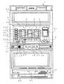
図1は本実施形態によるスロットマシン1の正面図である。
FIG. 1 is a front view of the
スロットマシン1の前面パネル2の背後には可変表示装置を構成する3個のリール3,4,5が回転自在に設けられている。各リール3,4,5の外周面には複数種類の図柄(以下、シンボルという)から成るシンボル列が描かれている。これらシンボルはスロットマシン1の正面の表示窓6,7,8を通してそれぞれ3個ずつ観察される。また、表示窓6,7,8の下方右側には、遊技者がメダルを入れるための投入口9が設けられている。
Three
各リール3〜5は図2に示す回転リールユニットとして構成されており、フレーム51にブラケット52を介して取り付けられている。各リール3〜5はリールドラム53の外周にリール帯54が貼られて構成されている。リール帯54の外周面には上記のシンボル列が描かれている。また、各ブラケット52にはステッピングモータ55が設けられており、各リール3〜5はこれらモータ55が駆動されて回転する。
Each
各リール3〜5の構造は図3(a)に示される。なお、同図において図2と同一部分には同一符号を付してその説明は省略する。リール帯54の背後のリールドラム53内部にはランプケース56が設けられており、このランプケース56の3個の各部屋にはそれぞれバックランプ57a,57b,57cが取り付けられている。これらバックランプ57a〜57cは図3(b)に示すように基板58に実装されており、この基板58がランプケース56の背後に取り付けられている。また、ブラケット52にはホトセンサ59が取り付けられている。このホトセンサ59は、リールドラム53に設けられた遮蔽板60がリールドラム53の回転に伴ってホトセンサ59を通過するのを検出する。
The structure of each of the
各バックランプ57a〜57cは後述するランプ駆動回路48によって点灯制御される。各バックランプ57a〜57cの点灯により、リール帯54に描かれたシンボルの内、各バックランプ57の前部に位置する3個のシンボルが背後から個別に照らし出され、各表示窓6〜8にそれぞれ3個ずつのシンボルが映し出される。
Each of the back lamps 57a to 57c is controlled to be lit by a lamp driving circuit 48 described later. When the back lamps 57a to 57c are turned on, among the symbols drawn on the reel band 54, three symbols located at the front of each
また、図1に示す表示窓6〜8には、横3本(中央L1および上下L2A,L2B)および斜め2本(斜め右下がりL3A,斜め右上がりL3B)の入賞ラインが記されている。ゲーム開始に先立ち、遊技者がメダル投入口9に1枚のメダルを投入したときは、各リール3〜5上にある中央の入賞ラインL1だけが図4(a)に示すように有効化される。また、2枚のメダルを投入口9に投入したときはこれに上下の入賞ラインL2A,L2Bが加わり、横3本の入賞ラインL1,L2AおよびL2Bが同図(b)に示すように有効化される。また、3枚のメダルを投入口9に投入したときは全ての入賞ラインL1,L2A,L2B,L3AおよびL3Bが同図(c)に示すように有効化される。
In addition, in the
なお、同図における丸印は各リール3〜5上に描かれたシンボルを表している。このような入賞ラインの有効化は、各入賞ラインの端部に配置された有効化ライン表示ランプ23(図1参照)が点灯することにより、遊技者に表示される。
Note that the circles in the figure represent symbols drawn on the
また、表示窓6〜8の下方左側には、1BETスイッチ10,2BETスイッチ11およびマックスBETスイッチ12が設けられている。クレジット数表示部13にメダルがクレジットされている場合には、メダル投入口9へのメダル投入に代え、これら1BETスイッチ10,2BETスイッチ11およびマックスBETスイッチ12の各押ボタン操作により、1回のゲームにそれぞれ1枚,2枚および3枚のメダルが賭けられる。クレジット数表示部13は、表示する数値の桁数に応じた個数の7セグメントLEDで構成されており、現在クレジットされているメダル数を表示する。
A 1
これらBETスイッチ10〜12の下方にはクレジット/精算切換スイッチ(C/Pスイッチ)14およびスタートレバー15が設けられており、スタートレバー15の右方の機器中央部には停止ボタン16,17,18が設けられている。C/Pスイッチ14の押しボタン操作により、メダルのクレジット/払い出し(PLAY CREDIT/PAY OUT)を切り換えることが出来る。
Below these BET switches 10-12, a credit / payment changeover switch (C / P switch) 14 and a
スタートレバー15のレバー操作により、リール3,4,5の回転が一斉に開始する。停止ボタン16,17,18は、各リール3,4,5の回転表示を各列毎に停止させる可変表示停止手段を構成しており、各リール3,4,5に対応して配置されている。各リール3〜5の回転速度が一定速度に達したときに各停止ボタン16〜18の操作が有効化され、各停止ボタン16〜18は遊技者の押しボタン操作に応じて各リール3〜5の回転を停止させる。
By the lever operation of the
本実施形態によるスロットマシンでは、一番最初に停止操作される第1停止リールおよびその次に停止操作される第2停止リールについては、CT期間中、後述する停止表示制御手段による停止表示制御が中断される。つまり、第1停止リールおよび第2停止リールは、遊技者の停止ボタン16〜18の操作タイミングにのみ応じて直ちに停止される。これに対して最後に停止操作される第3停止リールについては、CT期間中であっても停止表示制御手段による停止表示制御が行われる。つまり、第3停止リールは、第1停止リールおよび第2停止リールが停止表示するシンボルの組合せによって発生し得る入賞役に応じたシンボルを停止表示するよう、制御される。ただし、この際、引き込み制御されるシンボルのコマ数は後述するように減らされる。
In the slot machine according to the present embodiment, for the first stop reel to be stopped first and the second stop reel to be stopped next, stop display control by stop display control means described later is performed during the CT period. Interrupted. That is, the first stop reel and the second stop reel are immediately stopped only according to the operation timing of the
また、スロットマシン1の正面下部には透音孔19およびメダル受皿20が設けられている。透音孔19は、機器内部に収納されたスピーカから発生した音を外部へ出すものである。メダル受皿20はメダル払出口21から払い出されるメダルを貯めるものである。また、スロットマシン1の正面上部には、各入賞に対してどれだけのメダルが払い出されるかが示されている配当表示部22が設けられている。
In addition, a
また、各リール3,4,5の右方の前面パネル2には液晶表示部24が設けられている。この液晶表示部24は各リール3,4,5の回転表示をしたり、遊技履歴を表示したり、ボーナスゲーム中に演出を行ったりするディスプレイ装置である。
A liquid
図5は、本実施形態のスロットマシン1における遊技処理動作を制御する制御部と、これに電気的に接続された周辺装置(アクチュエータ)とを含む回路構成を示している。
FIG. 5 shows a circuit configuration including a control unit that controls a game processing operation in the
制御部はマイクロコンピュータ(以下、マイコンという)30を主な構成要素とし、これに乱数サンプリングのための回路を加えて構成されている。マイコン30は、予め設定されたプログラムに従って制御動作を行うCPU31と、記憶手段であるROM32およびRAM33を含んで構成されている。CPU31には、基準クロックパルスを発生するクロックパルス発生回路34および分周器35と、一定範囲の乱数を発生させる乱数発生器36および発生した乱数の中から任意の乱数を抽出する乱数サンプリング回路37が接続されている。
The control unit includes a microcomputer 30 (hereinafter referred to as a microcomputer) as a main component, and is configured by adding a circuit for sampling random numbers. The
マイコン30からの制御信号により動作が制御される主要なアクチュエータとしては、リール3,4,5を回転駆動する各ステッピングモータ55、メダルを収納するホッパ38、液晶表示部24、スピーカ39およびバックランプ57がある。これらはそれぞれモータ駆動回路40、ホッパ駆動回路41、表示駆動回路42、スピーカ駆動回路43およびランプ駆動回路48によって駆動される。これら駆動回路40〜43,48は、マイコン30のI/Oポートを介してCPU31に接続されている。各ステッピングモータ55はモータ駆動回路40によって1−2相励磁されており、400パルスの駆動信号が供給されるとそれぞれ1回転する。
The main actuators whose operation is controlled by a control signal from the
また、マイコン30が制御信号を生成するために必要な入力信号を発生する主な入力信号発生手段としては、スタートレバー15の操作を検出するスタートスイッチ15Sと、メダル投入口9から投入されたメダルを検出する投入メダルセンサ9Sと、前述したC/Pスイッチ14とがある。また、ホトセンサ59、およびこのホトセンサ59からの出力パルス信号を受けて各リール3,4,5の回転位置を検出するリール位置検出回路44もある。
The main input signal generating means for generating an input signal necessary for the
ホトセンサ59は各リール3,4,5が一回転する毎に遮蔽板60を検出してリセットパルスを発生する。このリセットパルスはリール位置検出回路44を介してCPU31に与えられる。RAM33内には、各リール3〜5について、一回転の範囲内における回転位置に対応した計数値が格納されており、CPU31はリセットパルスを受け取ると、RAM33内に形成されたこの計数値を“0”にクリアする。このクリア処理により、各シンボルの移動表示と各ステッピングモータ55の回転との間に生じるずれが、一回転毎に解消されている。
The
さらに、上記の入力信号発生手段として、リール停止信号回路45と、払出し完了信号発生回路46とがある。リール停止信号回路45は、停止ボタン16,17,18が押された時に、対応するリール3,4,5を停止させる信号を発生する。また、メダル検出部47はホッパ38から払い出されるメダル数を計数し、払出し完了信号発生回路46は、このメダル検出部47から入力した実際に払い出しのあったメダル計数値が所定の配当枚数データに達した時に、メダル払い出しの完了を知らせる信号をCPU31へ出力する。
Further, the input signal generating means includes a reel stop signal circuit 45 and a payout completion
ROM32には、このスロットマシン1で実行されるゲーム処理の手順がシーケンスプログラムとして記憶されている他、入賞確率テーブル,シンボルテーブル、および入賞シンボル組合せテーブル等がそれぞれ区分されて格納されている。
The
入賞確率テーブルは、サンプリング回路37で抽出された乱数を各入賞態様に区分けするために使用され、乱数発生器36で発生する一定範囲の乱数を各入賞態様に区画するデータを記憶している。このような入賞確率テーブルは例えば図6に示すように構成される。同図におけるa1〜a3,b1〜b3,c1〜c3,d1〜d3,e1〜e3,f1〜f3,g1〜g3は予め設定された数値データであり、サンプリング回路37で抽出された乱数を各入賞態様に区画する際に用いられる。このデータは、投入メダル枚数が1枚の場合には「a1〜g1」、2枚の場合には「a2〜g2」、3枚の場合には「a3〜g3」の各数値の組合せが用いられる。
The winning probability table is used to divide the random number extracted by the
これら数値は通常「a<b<c<d<e<f<g」の大小関係に設定され、抽出された乱数値がa未満であれば大当たり入賞(大ヒット)となって「BB」当選フラグが立つ。また、抽出された乱数値がa以上b未満であれば中当たり入賞(中ヒット)となって「RB」当選フラグが立つ。また、抽出された乱数値がb以上f未満であれば小当たり入賞(小ヒット)となり、この場合、b以上c未満の場合には「プラム」当選フラグが立ち、c以上d未満の場合には「ベル」当選フラグ、d以上e未満の場合には「4枚チェリー」当選フラグ、e以上f未満の場合には「2枚チェリー」当選フラグが立つ。また、抽出された乱数値がf以上g未満であれば「再遊技」当選フラグが立ち、g以上であれば入賞なしの「ハズレ」当選フラグが立つ。 These numbers are usually set to a magnitude relationship of “a <b <c <d <e <f <g”, and if the extracted random number value is less than a, it becomes a big win (big hit) and “BB” is won. A flag stands. Also, if the extracted random value is greater than or equal to a and less than b, it becomes a middle win (medium hit) and the “RB” winning flag is set. In addition, if the extracted random number value is not less than b and less than f, a small winning prize (small hit) is obtained. Is a “bell” winning flag, a “four cherry” winning flag is set when d is less than e and a “two cherry” winning flag is set when e is less than f. Further, if the extracted random value is greater than or equal to f and less than g, a “replay” winning flag is set, and if it is not less than g, a “losing” winning flag without winning is set.
つまり、入賞態様は、サンプリングされた1つの乱数値がこのどの数値範囲に属するかによって決定され、「ハズレ」および「再遊技」を含めて合計8種類の当選フラグによって表される。ここで、乱数発生器36,サンプリング回路37,入賞確率テーブルおよびマイコン30は、乱数抽選によって遊技の入賞態様を決定する入賞態様決定手段を構成している。
In other words, the winning mode is determined by which numerical value range one sampled random number value belongs to, and is represented by a total of eight types of winning flags including “losing” and “replay”. Here, the
ただし、CT期間中においては、この入賞態様決定手段で小当たり入賞が決定されても、上記の小当たり入賞の当選フラグは立たないように制御される。つまり、CT期間では、小当たり入賞の抽選は行われなくなり、ボーナス入賞(BB,RB入賞)と再遊技とについてだけ、抽選が行われる。 However, during the CT period, even if the small winning prize is determined by the winning mode determining means, the winning flag for the small winning prize is controlled so as not to stand. In other words, in the CT period, the lottery for the small winning prize is not performed, and the lottery is performed only for the bonus prize (BB, RB prize) and the replay.
また、シンボルテーブルは図7に概念的に示される。このシンボルテーブルは各リール3〜5の回転位置とシンボルとを対応づけるものであり、シンボル列を記号で表したものである。このシンボルテーブルにはコードナンバに対応したシンボルコードが各リール3〜5毎に記憶されている。コードナンバは、前述したリセットパルスが発生する回転位置を基準として各リール3〜5の一定の回転ピッチ毎に順次付与されている。シンボルコードはそれぞれのコードナンバ毎に対応して設けられたシンボルを示している。
The symbol table is conceptually shown in FIG. This symbol table associates the rotational positions of the
また、入賞シンボル組合せテーブルには、配当表示部22に示される各入賞シンボル組合せのシンボルコードや、特定ゲーム発生のフラグが成立していることを遊技者に示唆する「リーチ目」を構成するシンボル組合せのシンボルコード、各入賞を表す入賞判定コード、入賞メダル配当枚数等が記憶されている。この入賞シンボル組合せテーブルは、第1リール3,第2リール4、第3リール5の停止制御時、および全リール停止後の入賞確認を行うときに参照される。
Further, in the winning symbol combination table, symbols constituting “reach eyes” that indicate to the player that a symbol code of each winning symbol combination shown in the payout display section 22 and a flag indicating that a specific game has occurred are established. A combination symbol code, a prize determination code representing each prize, a prize medal payout number, and the like are stored. This winning symbol combination table is referred to when the
リール位置検出回路44,リール停止信号回路45,モータ駆動回路40,ステッピングモータ55およびマイコン30は、停止表示制御手段を構成している。この停止表示制御手段は、停止ボタン16〜18の操作タイミングをリール停止信号回路45によって検出し、この操作タイミングに有効化ライン上に表示されるシンボルが入賞態様に応じたシンボルでなく、有効化ライン上に続いて表示される4コマ分のシンボルの中に入賞態様に応じたシンボルが存在する場合、このシンボルを表示窓6〜8の有効化ライン上に引き込む制御をする。この際、リール位置検出回路44によって表示窓6〜8に表示されるシンボルの種類が把握されながら、モータ駆動回路40およびステッピングモータ55がマイコン30によって制御され、リール3〜5の回転制御が行われる。
The reel
また、マイコン30は制御中断手段をも構成している。この制御中断手段は、特定の条件が成立したとき、つまり、後述する乱数抽選に当選したときに作動し、予め定められた条件に従って、停止表示制御手段による入賞態様に応じたシンボルの停止表示制御を第1停止リールおよび第2停止リールについて中断する。この予め定められた条件は、本実施形態では、予め定められた回数分の遊技が行われるまでか、または所定枚数のメダルが払い出されるまでかのいずれか早い方が達成するまで、ということが条件になっており、この条件が成立するまで停止表示制御手段による停止制御が中断される。
The
本実施形態によるCT機と呼ばれるスロットマシンでは、この制御中断手段は、小当たり入賞態様に対してだけ停止表示制御手段によるシンボルの停止表示制御を中断する。また、CT期間中には、停止表示制御手段は、制御中断手段によって入賞態様に応じたシンボルの停止表示制御が第1停止リールおよび第2停止リールについて中断されている間、第3停止リールについて引き込むシンボルのコマ数を、例えば、後述するように4コマから1コマまたは0コマに減らす。 In the slot machine called a CT machine according to the present embodiment, this control interruption means interrupts the symbol stop display control by the stop display control means only for the small winning prize mode. In addition, during the CT period, the stop display control unit performs the third stop reel while the symbol stop display control according to the winning mode is interrupted for the first stop reel and the second stop reel by the control interrupt unit. For example, the number of symbols to be drawn is reduced from 4 frames to 1 frame or 0 frame as described later.
次に、本実施形態においてマイコン30で制御される遊技機の動作について説明する。
Next, the operation of the gaming machine controlled by the
図8および図9はこの遊技処理の概略を示すフローチャートである。 8 and 9 are flowcharts showing the outline of this game process.
まず、前回の遊技の結果再遊技(リプレイ)が生じ、メダルの自動投入があるか否かがCPU31によって判別される(図8,ステップ101参照)。この自動投入がある場合には、次に、投入要求分の遊技メダルが自動投入される(ステップ102)。一方、自動投入がない場合には、次に、遊技者によってメダル投入口9にメダルが投入され、メダルセンサ9Sから検出信号が入力されるのを待つ(ステップ103)。または、遊技者によってBETスイッチ10,11,12が操作され、これらスイッチからの信号が入力されるのを待つ。一般遊技中は最大3枚までのメダルを投入することが出来、BBゲームやRBゲーム中のボーナスゲームでは1枚のメダルを投入することが出来る。
First, replay (replay) occurs as a result of the previous game, and the
次に、スタートレバー15の操作により、スタートスイッチ15Sからのスタート信号入力があったか否かが判別される(ステップ104)。この判別が“YES”の場合、次に、前回の遊技から4.1秒経過しているか否かが判別される(ステップ105)。4.1秒経過していない場合には、4.1秒経過するまで遊技開始の待ち時間が消化される(ステップ106)。4.1秒経過すると、次に、入賞態様決定手段によって入賞判定が行われる。つまり、乱数発生器36で発生した抽選用の乱数がサンプリング回路37によって抽出され(ステップ107)、確率抽選処理が行われる(ステップ108)。
Next, it is determined whether or not a start signal is input from the start switch 15S by operating the start lever 15 (step 104). If this determination is “YES”, it is then determined whether 4.1 seconds have elapsed since the previous game (step 105). If 4.1 seconds have not elapsed, the game start waiting time is consumed until 4.1 seconds have elapsed (step 106). When 4.1 seconds have elapsed, the winning determination is performed by the winning mode determining means. That is, the random number for lottery generated by the
この確率抽選処理は、前述したように、サンプリング回路37によって特定された1つの乱数値が、入賞確率テーブル(図6参照)においてどの入賞グループに属する値になっているか判断されることによって行われる。この入賞態様決定手段で決定された入賞態様は当選フラグの種類によって表され、「ハズレ」,「再遊技」,「2枚チェリー」,「4枚チェリー」,「ベル」,「プラム」,「RB」および「BB」の8種類の中のいずれか1つの当選フラグがRAM33の所定領域にセットされる。
As described above, this probability lottery process is performed by determining to which winning group a single random value specified by the
また、この確率抽選処理の結果、「BB」当選フラグが立ってBB内部当たりが生じた場合には、続いてCT遊技の抽選が行われる。このCT遊技の抽選も、入賞態様決定のための上記の確率抽選処理と同様、乱数発生器36で発生した乱数がサンプリング回路37によって抽出されて行われる。そして、サンプリングされたこの乱数値が特定値と大小関係が比較され、例えばサンプリングされた乱数値が特定値よりも小さい場合に当選となり、抽選結果が決定される。この抽選の結果が当選したことは、特定条件が成立したことに相当する。
As a result of the probability lottery process, when the “BB” winning flag is set and the BB internal hit occurs, the CT game lottery is subsequently performed. The lottery of the CT game is also performed by extracting the random number generated by the
このような特定条件が成立して行われるCT遊技は、BBゲームの終了後に引き続いて行われる。このCT期間では、ステップ108における入賞態様の決定のための確率抽選処理は、前述したように、小当たり入賞の抽選結果は無効化され、いわゆるボーナス入賞(BB,RB入賞)と再遊技とについてだけ行われる。
The CT game that is performed under such a specific condition is continued after the end of the BB game. In this CT period, the probability lottery process for determining the winning mode in
次に、リール3〜5の各回転位置が書き込まれるRAM33の所定領域が、リール回転の開始に際して初期化され(ステップ109)、引き続いて各リール3〜5がステッピングモータ55によって回転駆動される。次に、何れかの停止ボタン16〜18がオン操作されたか否かが判別される(ステップ110)。オン操作されていない場合には、自動停止タイマーが0になったか否かが判別される(ステップ111)。この自動停止タイマーは、停止ボタン16〜18が所定時間操作されない場合に、各リール3〜5を所定時間経過後に自動的に停止させるためのものである。
Next, a predetermined area of the RAM 33 in which the rotational positions of the
何れかの停止ボタン16〜18がオン操作されたか、または、自動停止タイマーが0になると、次に、停止表示制御手段によって有効化ライン上に引き込まれるシンボルのコマ数、つまり滑りコマ数が決定される(ステップ112)。この滑りコマ数は、遊技状態,当選要求,制御コマ数,図柄位置等から定められる。
When any one of the
遊技状態は、RAM33の遊技状態ステータスという1バイトの領域に格納されている。遊技状態には、「RB作動中」,「BB作動中」,「一般遊技中」,「BB内部当たり中」,「RB内部当たり中」および「CT期間中」の6種類がある。 The gaming state is stored in a 1-byte area called a gaming state status in the RAM 33. There are six game states: “RB in operation”, “BB in operation”, “general game”, “inside BB inside”, “inside RB inside”, and “during CT period”.
「RB作動中」はRBゲーム中の遊技状態を表している。RBはレギュラー・ボーナス・ゲームを意味しており、このRBゲームでは複数回の高配当ゲームが一組となったボーナスゲームが1回行える。「BB作動中」はBBゲーム中の遊技状態を表している。BBはビッグ・ボーナス・ゲームを意味しており、このBBゲームでは一般遊技および上記のボーナスゲームのセットを複数回行うことが出来る。「一般遊技中」はBB,RBのいずれの入賞も生じていない遊技状態を表している。 “RB in operation” represents a gaming state during an RB game. RB means a regular bonus game. In this RB game, a bonus game in which a plurality of high payout games are combined can be played once. “BB in operation” represents a gaming state during the BB game. BB means a big bonus game. In this BB game, a general game and the above-described bonus game can be set a plurality of times. “In general game” represents a gaming state in which neither BB nor RB winning has occurred.
「BB内部当たり中」はBB当選フラグは立っているが、各リール3〜5に所定の入賞シンボル組合せが停止表示されず、未だBBゲームに突入していない一般遊技状態のことを表している。「RB内部当たり中」はRB当選フラグは立っているが、各リール3〜5に所定の入賞シンボル組合せが停止表示されず、未だRBゲームに突入していない一般遊技状態のことを表している。
“Inside BB hit” indicates a general gaming state in which the BB winning flag is set but a predetermined winning symbol combination is not stopped and displayed on each
「CT期間中」は、前述したようにBB,RBゲームおよびリプレイの入賞役の抽選は行っているが、小当たり入賞役の抽選が無効化される遊技状態を表している。小当たり入賞には、有効化ライン上にプラムのシンボルが揃って発生するプラム,ベルのシンボルが揃って発生するベル,チェリーのシンボルが揃って発生する2枚チェリーおよび4枚チェリーがある。 “During CT period” represents a gaming state in which the lottery of the winning combination for the BB, RB game and replay is invalidated, but the lottery of the small winning combination is invalidated. There are two types of small winning prizes: a plum that is generated with a set of plum symbols on the activation line, a bell that is generated with a set of bell symbols, a two-cherry and a four-cherry that are generated with a set of cherry symbols.
当選要求も、RAM33の当たり要求フラグ格納領域に記憶されている。この領域も1バイトからなり、当たり要求フラグには「CT無しBB」,「CT付きBB」,「RB」,「リプレイ」,「ベル」,「プラム」,「4枚チェリー」および「2枚チェリー」の8種類がある。ここで、「CT無しBB」は、ステップ108の確率抽選処理でBBの内部当たりが有り、その後のCT遊技の抽選で外れた場合にセットされる当たり要求フラグである。「CT付きBB」は、確率抽選処理でBBの内部当たりが有り、その後のCT遊技の抽選でも当選した場合にセットされる当たり要求フラグである。
The winning request is also stored in the hit request flag storage area of the RAM 33. This area also consists of 1 byte, and the hit request flags include “BB without CT”, “BB with CT”, “RB”, “Replay”, “Bell”, “Plum”, “4 Cherry” and “2” There are 8 types of “cherry”. Here, “BB without CT” is a hit request flag that is set when there is an internal hit of the BB in the probability lottery process of
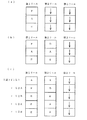
制御コマ数は、図10に示すように、引き込み制御が優先されるシンボルの順位に応じ、RAM33にテーブルとして格納されている。同図(a)は一般遊技中における引込優先順位テーブルであり、一般遊技中では、リプレイ,小当たり,BB・RBゲームの順に優先順位が決められている。この優先順位は、有効化ライン上に優先して引き込まれる入賞役の優先順位である。制御コマ数は停止表示制御手段によって引き込み制御可能な範囲のコマ数であり、一般遊技中では各入賞役とも4コマに設定されている。 As shown in FIG. 10, the number of control frames is stored as a table in the RAM 33 in accordance with the order of symbols for which pull-in control is prioritized. FIG. 4A is a drawing priority order table in a general game. In the general game, the priority order is determined in the order of replay, small hit, and BB / RB game. This priority order is a priority order of winning combinations that are drawn preferentially on the activation line. The number of control frames is the number of frames in a range that can be pulled in and controlled by the stop display control means. In a general game, each winning combination is set to 4 frames.
同図(b)はCT期間中における引込優先順位テーブルであり、CT期間中では、プラム,ベル,4枚チェリー,2枚チェリーの順に小当たり入賞役が引込制御される。また、制御コマ数はプラム,ベルについては1コマ、4枚チェリー,2枚チェリーについては0コマに設定されている。制御コマ数が0ということは、引き込み制御を行わないということを意味している。 FIG. 5B is a drawing priority table during the CT period. During the CT period, the small winning combination is controlled in the order of plum, bell, four cherries, and two cherries. The number of control frames is set to 1 frame for plum and bell, 4 cherries, and 0 frame for 2 cherries. A control frame number of 0 means that pull-in control is not performed.
図柄位置は、ステップ109で初期化されたRAM33の領域に書き込まれた各リール3〜5の位置データである。この図柄位置は、各有効化ライン上にその時に存在するシンボルのデータであり、図7に示すシンボルコードとして記憶されている。
The symbol position is the position data of each
滑りコマ数の決定に際しては、まず、現在の遊技状態が参照され、遊技状態に応じた優先順位テーブルが選択される。つまり、一般遊技状態であれば図10(a)に示すテーブルが選択され、CT期間中であれば図10(b)に示すテーブルが選択される。次に、当選要求に応じた当選役の制御コマ数が選択したテーブルから参照される。その後、そのときの図柄位置が参照され、第1停止リールの有効化ライン上にそのときにあるシンボルが把握される。このシンボルが当選要求に応じたシンボルではない場合、参照された制御コマ数の範囲内に当選要求に応じたシンボルがあるか否か判別される。もしも、当選要求に応じたシンボルが制御コマ数の範囲内に有る場合、有効化ラインからそのシンボルまでのコマ数が滑りコマ数として決定される。 In determining the number of sliding symbols, first, the current gaming state is referred to, and a priority table corresponding to the gaming state is selected. That is, the table shown in FIG. 10A is selected in the general gaming state, and the table shown in FIG. 10B is selected in the CT period. Next, the control frame number of the winning combination corresponding to the winning request is referred from the selected table. Thereafter, the symbol position at that time is referred to, and the symbol at that time is grasped on the activation line of the first stop reel. If this symbol is not a symbol corresponding to the winning request, it is determined whether or not there is a symbol corresponding to the winning request within the range of the reference control frame number. If the symbol corresponding to the winning request is within the range of the number of control frames, the number of frames from the activation line to the symbol is determined as the number of sliding frames.
次に、このように決定された滑りコマ数分だけ第1停止リール(回胴)が回転するよう、この滑りコマ数がRAM33の所定領域に格納される(ステップ113)。ただし、CT期間中においては、第1停止リールおよび第2停止リールについては停止表示制御が行われないため、ステップ112およびステップ113は実行されない。その後、第1停止リールについての停止要求フラグがセットされる(ステップ114)。停止表示制御手段はこの停止要求フラグがセットされるのに応じ、1個のリールの回転を停止させる。 Next, the number of sliding frames is stored in a predetermined area of the RAM 33 so that the first stop reel (rotating drum) rotates by the number of sliding frames determined in this way (step 113). However, during the CT period, since the stop display control is not performed for the first stop reel and the second stop reel, Step 112 and Step 113 are not executed. Thereafter, a stop request flag for the first stop reel is set (step 114). The stop display control means stops the rotation of one reel in response to the stop request flag being set.
次に、全てのリールが停止したか否かが判別される(図9,ステップ115)。第2リールおよび第3リールが未だ停止していない場合には、処理はステップ110に戻り、以上の処理が繰り返して行われる。 Next, it is determined whether or not all reels have stopped (FIG. 9, step 115). If the second reel and the third reel have not yet stopped, the process returns to step 110, and the above processes are repeated.
停止表示制御手段によるこのステップ110〜115のリール停止処理は、一般遊技中には例えば次のように行われる。 The reel stop process in steps 110 to 115 by the stop display control means is performed, for example, as follows during the general game.
例えば、第1リール停止ボタン16のオン操作が検出された場合には、第1リール停止ボタン16が遊技者によって操作された時点で、第1リール3のステッピングモータ55に供給された駆動パルスの数がRAM33から読み出され、第1リール3の回転位置と対応づけられる。第1リール3の回転位置が分かると、シンボルテーブル(図7参照)との対照により、観察窓6に現れている3個のシンボルがシンボルコードとして把握される。
For example, when the on operation of the first
この場合、大ヒットの当選フラグが立っているときには、観察窓6の有効化入賞ライン上に大ヒットを構成するシンボルがあるか否かがチェックされる。同様に、中ヒット,小ヒットの当選フラグが立っているときには、観察窓6の有効化入賞ライン上に中ヒット,小ヒットを構成するシンボルがあるか否かがチェックされる。有効化入賞ライン上に当選フラグに対応したシンボルがあるときは、CPU31は即座に第1リール3を停止させる。
In this case, when the winning flag for the big hit is set, it is checked whether or not there is a symbol constituting the big hit on the activated pay line of the
上記のチェック処理により、当選フラグに対応したシンボルが観察窓6の有効化入賞ライン上に現れていない場合には、さらに第1リール3を制御コマ数(シンボル4コマ)分回転させたときにどのようなシンボルが現れてくるかをチェックする。もし、この中に当選フラグに対応するシンボルが有ったときには、そのコマ位置までが滑りコマ数であり、第1リール3を滑りコマ数分回転させてそこで停止させる。この引き込み制御処理は以下に説明する第2リール4および第3リール5の各停止制御処理時にも同様にして行われる。
If the symbol corresponding to the winning flag does not appear on the validation winning line of the
次に、第2リール4の停止ボタン17がオン操作された場合には、第2リール4の停止制御処理が行われる。この停止制御処理では、第2リール4が回転している状態で、まず、観察窓7の中央の入賞ラインL1にコードナンバ0〜20の21通りのシンボルが停止することを想定し、有効化入賞ライン上に既に停止している第1リール3のシンボルとの組合せが読み込まれる。また、第3リール5については回転中であることを表す回転コードが読み込まれる。なお、第2リール4も回転中であるが、上記処理によって停止されることを仮定しているため、回転コードとしては読み込まれない。
Next, when the
このようにしてシンボルコードの組合せが読み込まれると、前述した入賞シンボル組合せテーブルが参照され、第1リール3の停止により決定されたシンボルに対し、第2リール4が21通りの回転位置で停止したとき、有効化入賞ライン上にどのような入賞が生じる可能性があるかが順次判断されていく。例えば、図11(a)に示すように第1リール3が停止していたとすれば、第2リール4の停止位置を21通り想定してそのときのシンボル組合せパターンがチェックされる。例えば、同図(b)に示すように、第2リール4が観察窓7の中央でコードナンバ「5」で停止したとすると、各入賞ラインL1,L2A,L2B,L3A,L3B上でのシンボル組合せは同図(c)に示すようになる。
When the symbol code combination is read in this way, the above-described winning symbol combination table is referred to, and the
第3リール5の矢印は回転中であることを示す回転コードであるが、第3リールの停止位置によっては、入賞ラインL1に「A−A−A」の大ヒット入賞、入賞ラインL2Bに「E−E−E」の小ヒット入賞が生じる可能性がある。従って、第2リール4のコードナンバ「5」に対しては、図12に示すように大ヒットの予想フラグと小ヒットの予想フラグとがセットされる。このような予想フラグの有無が第2リール4の全てのコードナンバについてチェックされ、これらデータはRAM33に書き込まれる。
The arrow of the
このようにしてRAM33に書き込まれた予想フラグデータは、第2リール4の停止制御時に参照される。つまり、第2リール4の停止ボタン17が操作されたとき、第2リール4のコードナンバに対応する予想フラグが参照され、大ヒットの予想が発生している場合には、有効化入賞ライン上に大ヒットのシンボルが停止するように第2リール4の停止制御が実行される。
The prediction flag data written in the RAM 33 in this way is referred to when the
次に、第3リール5の停止ボタン18のオン操作が検出された場合には、第3リール5の停止制御処理が行われる。この停止制御処理では、既に第1リール3および第2リール4が停止してそのシンボルの組合せが特定されているので、これらのシンボルの組合せに対し、第3リール5の各々のコードナンバ毎に入賞の可能性が判定され、図12に示すテーブルと同様にして入賞予想フラグが立てられる。
Next, when an on operation of the
この予想フラグデータも第3リール5の停止ボタン18が操作されたときに参照され、大ヒットの予想が立っているときには、有効化入賞ライン上に大ヒットのシンボルが停止するように第3リール5の停止制御が実行される。この第3リール5の停止制御処理時には、既に停止している第1リール3,第2リール4のシンボルとの組合せによって当選フラグ通りの入賞が得られるだけでなく、当選フラグと異なる入賞が得られないようにリール停止位置が制御される。
The prediction flag data is also referred to when the
このような一般遊技中における停止表示制御手段によるリール停止処理は、CT期間中には、第1停止リールおよび第2停止リールについては行われない。つまり、上記の例と同様に、第1停止リールが第1リール3,第2停止リールが第2リール4の場合、これら各リール3,4は、停止ボタン16,17のオン操作が検出されたタイミングに直ちに停止する。つまり、遊技者による停止ボタン16,17の目押しタイミングのみに応じて各リール3,4は停止し、停止表示制御手段による引き込み制御は行われない。
Such reel stop processing by the stop display control means during the general game is not performed for the first stop reel and the second stop reel during the CT period. That is, as in the above example, when the first stop reel is the
また、CT期間中においては、第3停止リールについては停止表示制御が行われるが、この際行われる引き込み制御の制御コマ数は、図10(b)に示すように1または0となり、一般遊技中における制御コマ数4に比べて小さくなる。従って、例えば、第3停止リールが上記の例と同様に第3リール5である場合、停止ボタン18が操作されたタイミングに表示窓8の有効化入賞ライン上に入賞役に応じたシンボルが無い場合、有効化ラインから1コマまたは0コマの範囲内に入賞役に応じたシンボルが有るか否かが判別される。
Further, during the CT period, the stop display control is performed for the third stop reel, and the number of control frames of the pull-in control performed at this time is 1 or 0 as shown in FIG. This is smaller than the number of
例えば、第1リール3および第2リール4にプラムが揃っている場合、またはベルが揃っている場合にはプラムまたはベルが1コマまで引き込み制御される。つまり、停止ボタン18の操作タイミングに有効化ライン上にプラムまたはベルが存在しなくても、1コマの制御コマ数の範囲内にこれらシンボルが存在する場合、停止表示制御手段によって第3リール5が1コマだけ滑らせられ、プラムまたはベルの入賞が発生させられる。しかし、2枚チェリーおよび4枚チェリーの制御コマ数は0であるため、このような引き込み停止表示制御は行われない。
For example, when plums are aligned on the
このようなリール停止制御処理が終了すると、次に、入賞検索処理が行われる(図9,ステップ116)。この入賞検索処理では、有効化入賞ライン上に実際に揃っているシンボルの組合せの種類と、確率抽選処理によって当選した入賞フラグの種類との一致がとられる。そして、次にこの入賞フラグが正常か否かが判別される(ステップ117)。この判別結果が正常でない場合、例えば、ベルのシンボル組合せが有効化入賞ライン上に揃っているのに、入賞フラグがプラムのフラグである場合には、前面パネル2のメダル払出枚数表示ランプにイリーガルエラーが表示される(ステップ118)。
When the reel stop control process is completed, a winning search process is performed (step 116 in FIG. 9). In this winning search process, the type of combination of symbols actually arranged on the activated winning line is matched with the type of winning flag won by the probability lottery process. Next, it is determined whether or not the winning flag is normal (step 117). If the determination result is not normal, for example, if the combination of bell symbols is aligned on the activated pay line but the win flag is a plum flag, the medal payout number display lamp on the
入賞フラグが正常の場合には、次に、入賞枚数が0か否かが判別される(ステップ119)。入賞枚数が0でない場合には、次に、その時の状態によって遊技メダルの貯留、または払い出しを行う(ステップ120)。つまり、クレジットで遊技が行われている状態では、入賞によって獲得したメダル数分、クレジット数が増加され、また、投入口9へのメダル投入で遊技が行われている状態では、入賞によって獲得した枚数のメダルが受け皿20へ払い出される。
If the winning flag is normal, it is next determined whether or not the winning number is 0 (step 119). If the number of winning prizes is not 0, game medals are stored or paid out according to the state at that time (step 120). In other words, when the game is played with credit, the number of credits is increased by the number of medals won by winning, and when the game is played with the medal being inserted into the
次に、入賞態様が再遊技入賞か否かが判別され(ステップ121)、再遊技入賞の場合には自動投入要求がセットされる(ステップ122)。そして、次に、1遊技終了時の初期化、例えば、その遊技で使用したRAM33の領域が初期化され(ステップ123)、1遊技が終了する。 Next, it is determined whether or not the winning mode is a re-game winning (step 121), and in the case of a re-game winning, an automatic insertion request is set (step 122). Next, initialization at the end of one game, for example, the area of the RAM 33 used in the game is initialized (step 123), and one game is ended.
このような本実施形態では、上述したように、CT期間中、第1停止リールおよび第2停止リールについて小当たり入賞態様の停止表示制御が中断される。また、このCT期間中、第3停止リールについては、引き込まれるシンボルのコマ数が4コマから1コマまたは0コマに減る。従って、CT期間中における小当たり入賞態様の発生確率は従来のCT機に比較して低下し、遊技メダルの払い出し枚数は減少する。つまり、CT遊技における期待値は、その式中の引込データの値が小さくなるのに伴って小さくなり、一般遊技状態区分に定められた値である0.9以下に収まるようになる。このため、遊技店の損失が未然に防げ、また、初心者と熟練者との間におけるゲームの平等性が確保されるようになる。 In this embodiment, as described above, the stop display control in the small win winning mode is interrupted for the first stop reel and the second stop reel during the CT period. During the CT period, the number of symbols to be drawn is reduced from 4 frames to 1 frame or 0 frame for the third stop reel. Therefore, the probability of occurrence of the small winning prize mode during the CT period is lower than that of a conventional CT machine, and the number of game medals paid out is reduced. In other words, the expected value in the CT game becomes smaller as the value of the pull-in data in the equation becomes smaller, and falls within 0.9 or less, which is the value determined for the general gaming state category. For this reason, the loss of the game store can be prevented, and the equality of the game between the beginner and the expert can be ensured.
なお、上記実施形態の説明においては、CT期間中、停止表示制御手段による停止制御が中断されるリールを第1停止リールおよび第2停止リール、停止制御が行われるリールを第3停止リールとして説明したが、停止制御が中断されるリールの数および種類、並びに停止制御が行われるリールの数および種類はこれに限定されるものではない。例えば、停止制御が中断されるリールを第3停止リールとし、停止制御が行われるリールを第1停止リールおよび第2停止リールとしてもよい。 In the description of the above embodiment, the first stop reel and the second stop reel are referred to as the reels for which the stop control by the stop display control means is interrupted during the CT period, and the third stop reel is referred to as the stop control. However, the number and type of reels for which stop control is interrupted and the number and type of reels for which stop control is performed are not limited thereto. For example, a reel for which stop control is interrupted may be a third stop reel, and a reel for which stop control is performed may be a first stop reel and a second stop reel.
また、上記実施形態の説明においては、可変表示装置を回転リール3〜5として説明したが、この可変表示装置はこれに限定されるものではなく、例えば、液晶表示装置,プラズマディスプレイ装置,発光ダイオード(LED)や、エレクトロルミネセンスといった装置を可変表示装置としてもよい。
In the above description of the embodiment, the variable display device has been described as
このような各場合においても、上記実施形態と同様な効果が奏される。 In each of these cases, the same effects as those of the above embodiment can be obtained.
1…スロットマシン
2…前面パネル
3,4,5…第1,第2,第3リール
6,7,8…窓
9…メダル投入口
10,11,12…BETスイッチ
13…クレジット数表示部
14…クレジット/精算切換スイッチ
15…スタートレバー
16,17,18…停止ボタン
19…透音孔
20…メダル受皿
21…メダル払出口
22…配当表示部
23…有効化ライン表示ランプ
24…液晶表示部
L1,L2A,L2B,L3A,L3B…入賞ライン
DESCRIPTION OF
Claims (1)
前記制御中断手段は、小当たり入賞態様に対してだけ、前記停止表示制御手段による図柄の停止表示制御を、前記可変表示停止手段の第2停止操作に応じて停止される前記可変表示装置の第2停止表示列および前記可変表示停止手段の第3停止操作に応じて停止される前記可変表示装置の第3停止表示列について、中断し、
前記停止表示制御手段は、前記制御中断手段によって小当たり入賞態様に応じた図柄の停止表示制御が前記第2停止表示列および前記第3停止表示列について中断されている間、前記制御中断手段によって小当たり入賞態様に応じた図柄の停止表示制御が前記第2停止表示列および前記第3停止表示列について中断されていない間と比べて、前記可変表示停止手段の第1停止操作に応じて停止される前記可変表示装置の第1停止表示列について引き込む図柄の前記個数を変えて1個または0個に減らすことを特徴とする遊技機。
Winning mode determination means for determining the winning mode of the game by random number lottery, a variable display device that variably displays various symbols in a plurality of columns, and variable display stop that stops variable display of symbols by this variable display device for each column And a stop display for drawing and displaying the symbols corresponding to the winning mode determined by the winning mode determining unit within the predetermined number of ranges in the variable display device according to the operation timing of the variable display stopping unit. In accordance with a control unit and a predetermined condition when a specific condition is established, the stop display control of symbols according to the winning mode by the stop display control unit is interrupted for a part of the display columns of the variable display device. In a gaming machine configured with control interruption means,
The control interrupting means stops the symbol stop display control by the stop display control means in response to the second stop operation of the variable display stop means only for the small winning prize mode. 2 stop display rows and the third stop display row of the variable display device to be stopped in response to the third stop operation of the variable display stop means,
The stop display control means is configured so that the control interrupting means interrupts the symbol stop display control according to the small winning pattern with respect to the second stop display string and the third stop display string. Stop in response to the first stop operation of the variable display stop means, compared to when the stop display control of the symbol according to the small winning pattern is not interrupted for the second stop display row and the third stop display row A gaming machine, wherein the number of symbols drawn in the first stop display row of the variable display device is changed to 1 or 0 by changing.
Priority Applications (1)
| Application Number | Priority Date | Filing Date | Title |
|---|---|---|---|
| JP2005278727A JP2006015169A (en) | 2005-09-26 | 2005-09-26 | Game machine |
Applications Claiming Priority (1)
| Application Number | Priority Date | Filing Date | Title |
|---|---|---|---|
| JP2005278727A JP2006015169A (en) | 2005-09-26 | 2005-09-26 | Game machine |
Related Parent Applications (1)
| Application Number | Title | Priority Date | Filing Date |
|---|---|---|---|
| JP12524898A Division JP4111587B2 (en) | 1998-04-20 | 1998-04-20 | Game machine |
Publications (1)
| Publication Number | Publication Date |
|---|---|
| JP2006015169A true JP2006015169A (en) | 2006-01-19 |
Family
ID=35789882
Family Applications (1)
| Application Number | Title | Priority Date | Filing Date |
|---|---|---|---|
| JP2005278727A Withdrawn JP2006015169A (en) | 2005-09-26 | 2005-09-26 | Game machine |
Country Status (1)
| Country | Link |
|---|---|
| JP (1) | JP2006015169A (en) |
-
2005
- 2005-09-26 JP JP2005278727A patent/JP2006015169A/en not_active Withdrawn
Similar Documents
| Publication | Publication Date | Title |
|---|---|---|
| JP4111682B2 (en) | Game machine | |
| JP3712526B2 (en) | Game machine | |
| JP2000051433A (en) | Game machine | |
| JP4260270B2 (en) | Game machine | |
| JP4401490B2 (en) | Game machine | |
| JP2000308705A (en) | Game machine | |
| JP2002204850A (en) | Game machine | |
| JP2001009084A (en) | Game machine | |
| JP2003310869A (en) | Game machine | |
| JP2005152679A (en) | Game machine | |
| JP2007007133A (en) | Game machine | |
| JP2006238923A (en) | Game machine | |
| JP2003339945A (en) | Game machine | |
| JP4111587B2 (en) | Game machine | |
| JPH11309242A (en) | Game machine | |
| JP3062193B2 (en) | Gaming machine | |
| JP2002011151A (en) | Game machine | |
| JP2005152678A (en) | Game machine | |
| JP2005102956A (en) | Game machine | |
| JP2006320748A (en) | Game machine | |
| JP2000237378A (en) | Game machine | |
| JP2006015169A (en) | Game machine | |
| JP4536049B2 (en) | Game machine | |
| JP2006015168A (en) | Game machine | |
| JP2006015170A (en) | Game machine |
Legal Events
| Date | Code | Title | Description |
|---|---|---|---|
| A131 | Notification of reasons for refusal |
Free format text: JAPANESE INTERMEDIATE CODE: A131 Effective date: 20080513 |
|
| A761 | Written withdrawal of application |
Free format text: JAPANESE INTERMEDIATE CODE: A761 Effective date: 20080711 |