JP2005535456A - Method of operating welding apparatus and welding apparatus - Google Patents
Method of operating welding apparatus and welding apparatus Download PDFInfo
- Publication number
- JP2005535456A JP2005535456A JP2004518246A JP2004518246A JP2005535456A JP 2005535456 A JP2005535456 A JP 2005535456A JP 2004518246 A JP2004518246 A JP 2004518246A JP 2004518246 A JP2004518246 A JP 2004518246A JP 2005535456 A JP2005535456 A JP 2005535456A
- Authority
- JP
- Japan
- Prior art keywords
- welding
- computer unit
- message
- transmitted
- operating state
- Prior art date
- Legal status (The legal status is an assumption and is not a legal conclusion. Google has not performed a legal analysis and makes no representation as to the accuracy of the status listed.)
- Pending
Links
Images


Classifications
-
- B—PERFORMING OPERATIONS; TRANSPORTING
- B23—MACHINE TOOLS; METAL-WORKING NOT OTHERWISE PROVIDED FOR
- B23K—SOLDERING OR UNSOLDERING; WELDING; CLADDING OR PLATING BY SOLDERING OR WELDING; CUTTING BY APPLYING HEAT LOCALLY, e.g. FLAME CUTTING; WORKING BY LASER BEAM
- B23K9/00—Arc welding or cutting
- B23K9/10—Other electric circuits therefor; Protective circuits; Remote controls
- B23K9/1006—Power supply
- B23K9/1043—Power supply characterised by the electric circuit
- B23K9/1056—Power supply characterised by the electric circuit by using digital means
- B23K9/1062—Power supply characterised by the electric circuit by using digital means with computing means
Landscapes
- Engineering & Computer Science (AREA)
- Theoretical Computer Science (AREA)
- Physics & Mathematics (AREA)
- Plasma & Fusion (AREA)
- Mechanical Engineering (AREA)
- Arc Welding Control (AREA)
- General Factory Administration (AREA)
Abstract
本発明は、溶接装置(1)の動作方法に関する。溶接装置(1)は、制御装置(4)によって制御または調整されたエネルギー源(2)、特に電源と、少なくとも1つの溶接トーチ(10)または電極と、溶接温度など、動作状態を検出するための少なくとも1つの装置と、少なくとも1つの検出装置に接続され、動作状態の処理用に設けられた少なくとも1つのコンピュータユニット(29)とを備える。1つの装置(35)は、動作状態を処理するための規則および処理された動作状態を比較するための状態についての保存のために用いられる。本発明に係る溶接装置はまた、コンピュータユニット(29)に接続され、外部の受信器(37)へのメッセージを送信するための少なくとも1つの装置(36)を備え、比較結果の関数として割り当てられたメッセージが、前記外部の受信器(37)へ自動的に送信可能である。The present invention relates to a method for operating a welding apparatus (1). The welding device (1) detects an operating state such as an energy source (2) controlled or regulated by a control device (4), in particular a power source, at least one welding torch (10) or electrode, and welding temperature. At least one device and at least one computer unit (29) connected to at least one detection device and provided for processing of operating states. One device (35) is used for storing rules for processing operating states and states for comparing processed operating states. The welding device according to the invention is also connected to the computer unit (29) and comprises at least one device (36) for sending a message to an external receiver (37), assigned as a function of the comparison result. Messages can be automatically sent to the external receiver (37).
Description
本発明は、溶接トーチや電極に、制御または調整された電力が供給され、少なくとも溶接手順の間に、動作状態が検出されて、コンピュータユニットに送信され、前記コンピュータユニットで処理される溶接装置の動作方法に関する。 The present invention relates to a welding apparatus in which controlled or regulated power is supplied to a welding torch or electrode, an operating state is detected at least during a welding procedure, transmitted to a computer unit, and processed by the computer unit. It relates to the operation method.
また本発明は、好ましくは制御装置によって制御または調整されたエネルギー源、特に電源と、少なくとも1つの溶接トーチまたは電極、特に溶接ワイヤとを備え、さらに動作状態の検出用の少なくとも1つの装置と、少なくとも1つの検出装置に接続され、前記動作状態の処理用に設けられた少なくとも1つのコンピュータユニットとを備える溶接装置に関する。 The invention preferably also comprises an energy source, in particular a power source, and at least one welding torch or electrode, in particular a welding wire, controlled or regulated by a control device, and further comprising at least one device for detecting the operating state; The present invention relates to a welding apparatus including at least one computer unit connected to at least one detection device and provided for processing the operation state.
次に、溶接装置は、携帯用(hand-held)のものや溶接設備などの溶接装置を意味するものである。本発明は、MIG(金属−不活性ガス)溶接、MAG(金属−活性ガス)溶接、TIG(タングステン−不活性ガス)溶接などの類似の保護ガス溶接方法、あるいは他の種々のタイプの溶接方法など、種々の技術の溶接装置や溶接設備に適用可能である。 Next, the welding apparatus means a welding apparatus such as a hand-held one or a welding facility. The present invention relates to similar protective gas welding methods such as MIG (metal-inert gas) welding, MAG (metal-active gas) welding, TIG (tungsten-inert gas) welding, or various other types of welding methods. The present invention can be applied to welding apparatuses and welding equipment of various technologies.
完全または部分的に自動化された生産ラインでの溶接装置、特に溶接設備には、動作装置、制御装置および表示装置がますます装備されており、コンピュータ装置への接続やデータネットワークへの接続のためのインタフェースも装備される。例えば、OPC(object link embedding for process control)インタフェースなどのインタフェースが装備された最新の溶接装置は、例えば、インターネット上のコンピュータからのリモートコントロールや溶接手順に不可欠なデータの送信によるリモート診断を可能にする。こうしたデータを処理するために、溶接装置は、内部のコンピュータユニットを備えたり、前記インタフェースを経由してコンピュータユニットと接続されている。 Welding devices on fully or partially automated production lines, in particular welding equipment, are increasingly equipped with operating devices, control devices and display devices for connection to computer devices and data networks. The interface is also equipped. For example, the latest welding equipment equipped with an interface such as an OPC (object link embedding for process control) interface enables remote diagnosis from, for example, remote control from a computer on the Internet and transmission of data essential for welding procedures. To do. In order to process such data, the welding apparatus includes an internal computer unit or is connected to the computer unit via the interface.
少なくとも溶接手順の間に溶接装置の動作状態をモニタするために、溶接手順に不可欠なパラメータが検出される。動作状態という用語は、溶接電流、温度、保護ガスに関するデータや、例えば、溶接プロセスや溶接結果を表示する視覚的に検出したデータ、あるいは制御情報などの動作パラメータを含むものである。そして、カメラを用いて溶接場所を記録して、例えば、消費された電極など、溶接プロセス中に発生した問題を適切な画像処理によって判断できることが便利である。同様にして、溶接が完了した後、溶接部の記録写真から溶接部の品質を判断することも可能であろう。 In order to monitor the operating state of the welding apparatus at least during the welding procedure, parameters essential to the welding procedure are detected. The term operating condition includes operating parameters such as data relating to welding current, temperature, protective gas, visually detected data displaying the welding process and welding results, or control information. It is convenient to record the welding location using a camera and to determine, by appropriate image processing, problems that occurred during the welding process, such as consumed electrodes. Similarly, after the welding is completed, it is possible to judge the quality of the welded portion from the recorded photograph of the welded portion.
最近では、溶接手順中のエラーなど、特殊な動作状態は、溶接装置の動作表示ユニットによって光学的または音響的に表示され、責任者は、次の機会に溶接装置でのこうしたエラーを認識して、その結果、これを除去することができる。エラーメッセージが中央ユニットに転送され、必要な対策を立てて、エラーを除去したり、動作状態を変化させるようにした方法も知られている。例えば、溶接手順中のエラーなど、特定の動作状態に関する個々の情報が責任者に個別に到着する前に、貴重な時間が過ぎてしまうことは頻繁にあり、可能性ある生産ロスによって高いコストが発生するであろう。 Recently, special operating conditions, such as errors during the welding procedure, are displayed optically or acoustically by the operation display unit of the welding apparatus, and the responsible person is aware of such errors in the welding apparatus at the next opportunity. As a result, this can be removed. There is also known a method in which an error message is transferred to the central unit, and necessary measures are taken to eliminate the error or change the operation state. For example, valuable time often passes before individual information about specific operating conditions, such as errors during the welding procedure, arrives individually at the person in charge, which can be costly due to potential production losses. Will occur.
本発明の目的は、最初に述べたような溶接装置の動作方法および上述したタイプの溶接装置を提供することであり、これは、一定の動作状態の高速検出を可能とし、長い中断時間を回避するために、個々の動作状態に関する情報が受信器に迅速に到着するように適切な対策を自動的にとることができる。 The object of the present invention is to provide a method for operating a welding apparatus as described at the outset and a welding apparatus of the type described above, which allows fast detection of certain operating conditions and avoids long interruption times. In order to do this, appropriate measures can be taken automatically so that information about individual operating conditions arrives quickly at the receiver.
本発明に係る目的は、方法に関して、検出された動作状態は、保存された規則(Vorschriften)に従って処理されて、保存された状態(states)と比較され、そして、比較結果の関数として自動的に割り当てられたメッセージが外部の受信器に送信されることによって、達成される。本発明に係る溶接方法によって、特別な動作状態は速やかに認識され、認識された動作状態の関数として割り当てられたメッセージが外部の受信器に送信される。これにより、例えば、溶接ワイヤ供給コイルをモニタすることによって、溶接ワイヤの動作状態が検出可能となり、そして、ワイヤの終わり寸前に、溶接ワイヤ供給が不足するということに割り当てられたメッセージが外部の受信器へ送信可能となる。外部の受信器は、例えば、新しい溶接ワイヤコイルを調達し、溶接装置に取り付けるべきことを注意している在庫管理者のコンピュータであってもよい。これにより、送信されたメッセージ、例えば、好ましくはテキスト形式で利用可能なエラーが、検出された動作状態に対して独自に割り当てられる。操作者による通常必要なエラーコードの翻訳は不必要となって、貴重な時間が節約され、エラーコードの誤った解釈に起因したエラーは減少するであろう。例えば、溶接ワイヤ供給モータの過電流を検出することも可能であり、定義された限界値を超過した時点で、コア汚染という割り当てられたメッセージを、責任者、例えば、溶接装置のメンテナンス者に送信することも可能である。 The object according to the present invention is that with respect to the method, the detected operating state is processed according to the stored rules (Vorschriften), compared with the stored states and automatically as a function of the comparison result. This is accomplished by sending the assigned message to an external receiver. With the welding method according to the invention, the special operating state is quickly recognized and a message assigned as a function of the recognized operating state is transmitted to an external receiver. This makes it possible to detect the operating state of the welding wire, for example by monitoring the welding wire supply coil, and the message assigned to the lack of welding wire supply just before the end of the wire is received externally. Can be sent to the device. The external receiver may be, for example, an inventory manager's computer that cares about procuring new welding wire coils and attaching them to the welding equipment. This uniquely assigns the transmitted message, for example an error, preferably available in text form, to the detected operating state. Translation of the error code normally required by the operator will be unnecessary, saving valuable time and reducing errors due to incorrect interpretation of the error code. For example, it is possible to detect an overcurrent of the welding wire supply motor, and when a defined limit value is exceeded, an assigned message of core contamination is sent to the responsible person, for example, the welding equipment maintainer. It is also possible to do.
本発明の他の特徴によれば、メッセージは、検出された動作状態と保存した状態との比較結果の関数として、割り当てられた外部の受信器に送信されることである。このことは、選択された人間や装置には、例えば、誤動作など、個々の動作状態に応じて適切なメッセージが提供されることになる。外部の受信器は、選択された人間に通知したり、あるいは新しい溶接ワイヤコイルを個々の供給者に発注することなど、自動的に必要な対策をとる種々の専門的な装置であってもよい。 According to another feature of the invention, the message is transmitted to the assigned external receiver as a function of the result of the comparison between the detected operating state and the stored state. This means that the selected person or device is provided with an appropriate message according to the individual operation state, such as a malfunction. The external receiver may be a variety of specialized devices that automatically take the necessary measures such as notifying selected humans or ordering new welding wire coils from individual suppliers. .
本発明に係る方法の他の改良は、メッセージが、検出された動作状態と保存した状態との比較結果の関数として、対応する割り当てられた方法で外部の受信器に送信されることで達成される。これにより、送信の方法が受信器のタイプに適応するようになる。こうして、例えば、工場管理者の携帯電話へのメッセージ送信を望む場合、こうした送信はショートメッセージ(SMS)の形式で実現されるとともに、供給者の通知は、ファクシミリ経由でも行われる。一方側でのメッセージと、他方側での外部の受信器およびこうした受信器への送信タイプについての個別の割り当ては、表形式またはデータベース形式で保存してもよい。個々のデータが常に更新され、メッセージが常に正しい受信器に到達することを確保するためには、これらのデータは、適切なデータネットワークを経由して入力され、修正されることが好ましい。 Another improvement of the method according to the invention is achieved in that the message is transmitted to an external receiver in a corresponding assigned manner as a function of the comparison result of the detected operating state and the stored state. The This allows the transmission method to be adapted to the receiver type. Thus, for example, when it is desired to send a message to a factory manager's mobile phone, such transmission is realized in the form of a short message (SMS) and the supplier's notification is also made via facsimile. Individual assignments for messages on one side and external receivers on the other side and transmission types to such receivers may be stored in tabular or database form. In order to ensure that the individual data is constantly updated and the message always reaches the correct receiver, these data are preferably entered and modified via an appropriate data network.
外部受信器へのメッセージ送信は、例えば、ネットワーク、特にインターネットを経由した電子メール形式、携帯ネットワークを経由したショートメッセージ(short message)形式、あるいは遠距離通信(telecommunication)ネットワークを経由したファクシミリ送信の形式など、種々の方法で実施してもよい。ショートメッセージという用語は、テキスト形式による従来のショートメッセージ形式(SMS−ショートメッセージサービス)と、最新のマルチメディアショートメッセージ(MMS−マルチメディアメッセージサービス)の両方を包含するものであり、後者を経由して、例えば、溶接場所を図示する画像などが送信可能になる。 Message transmission to an external receiver is, for example, an e-mail format via a network, particularly the Internet, a short message format via a mobile network, or a facsimile transmission format via a telecommunication network For example, various methods may be used. The term short message encompasses both the conventional short message format in text format (SMS-short message service) and the latest multimedia short message (MMS-multimedia message service). Thus, for example, an image showing the welding location can be transmitted.
テキスト形式で利用可能なメッセージは、音響信号に変換され、遠距離通信ネットワークまたはラジオ(radio)ネットワークを経由して受信器に送信されることが好ましい。この場合、割り当てられたメッセージは、受信器において適切な音声出力として発せられる。 Messages available in text form are preferably converted into acoustic signals and sent to the receiver via a telecommunications network or a radio network. In this case, the assigned message is emitted as an appropriate audio output at the receiver.
本発明の更なる特徴によれば、検出された動作状態は、標準化されたインタフェース、例えば、OPC(object link embedding for process control)インタフェースを経由してコンピュータユニットへ送信される。その結果、検出された動作状態は、溶接装置において、標準フォーマット、例えば、OPC標準フォーマットに変換され、コンピュータユニットへ送信される。こうした標準インタフェースの使用により、溶接装置と他の溶接装置やコンピュータユニット、データネットワークとの接続が容易になる。 According to a further feature of the present invention, the detected operating state is transmitted to the computer unit via a standardized interface, for example an object link embedding for process control (OPC) interface. As a result, the detected operating state is converted into a standard format, for example, an OPC standard format, and transmitted to the computer unit in the welding apparatus. The use of such a standard interface facilitates the connection of the welding device with other welding devices, computer units and data networks.
検出された動作状態のコンピュータユニットへの送信は、バイナリコード(binary code)で実施することが好ましい。 The transmission of the detected operating state to the computer unit is preferably carried out in binary code.
コンピュータユニットが、検出された動作状態を解釈するためには、コンピュータユニットへの送信前に、検出された動作状態の前処理が適切となろう。こうした前処理は、動作状態の検出用の装置で行ってもよく、例えば、センサ自体、あるいは別のマイクロプロセッサ、マイクロコントローラなどで行ってもよい。 In order for the computer unit to interpret the detected operating condition, pre-processing of the detected operating condition will be appropriate before transmission to the computer unit. Such pre-processing may be performed by an apparatus for detecting an operation state, and may be performed by, for example, the sensor itself, another microprocessor, a microcontroller, or the like.
検出された動作状態を処理するための上述の保存された規則、及び/又は、検出された動作状態と比較するための保存した状態もコンピュータユニットに保存してもよい。 The stored rules described above for processing the detected operating state and / or the stored state for comparison with the detected operating state may also be stored in the computer unit.
同様に、これらの規則及び/又は状態は、コンピュータユニットに接続されたデータベースにそれぞれ保存することが可能である。 Similarly, these rules and / or states can each be stored in a database connected to the computer unit.
幾つかの溶接装置を備える生産工場の場合、個別のメッセージを、個々に発する溶接装置に割り当て可能とするためには、溶接装置についての独自(unique)の識別番号(identification)が前記メッセージと共に外部受信器に送信される。宛先となった受信器は、関係する溶接装置を直ちに認識することになる。こうした独自の識別番号は、幾つかの溶接装置の間での相互通信にも必要になる。例えば、別の溶接装置が外部受信器として機能し、エラーメッセージなどの送信の際、例えば、前記メッセージを発した溶接装置から溶接手順を引き継ぐことが考えられる。 In the case of a production plant with several welding devices, in order to be able to assign individual messages to individually originating welding devices, a unique identification number for the welding device is external to the message. Sent to the receiver. The intended receiver will immediately recognize the welding device concerned. Such a unique identification number is also required for mutual communication between several welding devices. For example, when another welding apparatus functions as an external receiver and an error message or the like is transmitted, it is conceivable that, for example, the welding procedure is taken over from the welding apparatus that issued the message.
本発明に係る目的は、動作状態を処理するための規則および処理された動作状態を比較するための状態についての保存のための少なくとも1つの装置と、コンピュータユニットに接続され、外部の受信器へのメッセージ送信のための少なくとも1つの装置とを備え、比較結果の関数として割り当てられたメッセージは、前記外部受信器へ自動的に送信可能であるようにした、溶接装置によっても達成される。 The object according to the invention is to connect to a computer unit and to an external receiver, at least one device for storing rules for processing operating states and states for comparing processed operating states, and a computer unit The message assigned as a function of the comparison result is also achieved by a welding device, wherein the message assigned as a function of the comparison result can be automatically sent to the external receiver.
メッセージを送信するための装置は、例えば、データネットワーク、特にインターネットへの接続を含むコンピュータユニットでもよく、メッセージは電子メール形式で送信することができる。 The device for sending a message may be, for example, a computer unit including a connection to a data network, in particular the Internet, and the message can be sent in the form of an email.
送信装置は、携帯電話、特にGSM(global system for mobile communication)携帯電話でもよい。 The transmitting device may be a mobile phone, particularly a GSM (global system for mobile communication) mobile phone.
さらに、送信装置は、ファクシミリ送信機でもよく、個別のメッセージは、所望の受信器にファクシミリ経由で送信される。 Furthermore, the transmitting device may be a facsimile transmitter, and individual messages are transmitted via a facsimile to a desired receiver.
さらに、送信装置は、音響送信ユニットでもよく、メッセージを音響信号に変換して、適切な遠距離通信ネットワークやラジオネットワークを経由して応答可能な受信器へ送信可能になる。 Further, the transmission device may be an acoustic transmission unit, which converts a message into an acoustic signal and transmits it to a receiver that can respond via an appropriate telecommunication network or radio network.
溶接装置は、外部受信器へのメッセージ送信のための1つまたは幾つかの別々の装置を装備してもよい。送信装置は、溶接装置のコンピュータユニットに接続されており、溶接装置から分離して配置しもよく、これと一体化していてもよい。送信装置の外部配置では、幾つかの溶接装置と接続していてもよく、別々の溶接装置についてのメッセージを送信する機能が想定される。 The welding device may be equipped with one or several separate devices for sending messages to an external receiver. The transmission device is connected to the computer unit of the welding device, and may be arranged separately from the welding device, or may be integrated therewith. In the external arrangement of the transmitting device, it may be connected to several welding devices, and a function of transmitting a message about different welding devices is assumed.
動作状態の検出のための装置、例えば、センサなど、および溶接装置を動作させるためのエネルギー源の制御および調整のための任意の制御装置は、標準化されたインタフェース、特にOPC(object link embedding for process control)インタフェースによって、コンピュータユニットと接続していてもよい。標準化インタフェースによって、溶接装置と他の溶接装置やデータネットワークなどとの接続が簡素化されることになる。 Devices for the detection of operating conditions, such as sensors, and any control device for controlling and adjusting the energy source for operating the welding apparatus are standardized interfaces, in particular OPC (object link embedding for process control) interface may be connected to the computer unit. The standardized interface simplifies the connection between the welding apparatus and other welding apparatuses and data networks.
動作状態を処理するためのコンピュータユニットは、溶接装置と一体化していてもよく、これによりコンパクトなユニットとなる。 The computer unit for processing the operating state may be integrated with the welding apparatus, thereby making it a compact unit.
必要であれば、コンピュータユニットへの送信前に、検出された動作状態を前処理するためのユニットが設けられる。こうした前処理ユニットは、処理前に、誤った動作状態を認識したり、測定値や測定状態の平均値を求めることが可能になる。 If necessary, a unit is provided for preprocessing the detected operating state prior to transmission to the computer unit. Such a pre-processing unit can recognize an erroneous operation state and obtain a measurement value or an average value of the measurement state before processing.
コンピュータユニットに接続されたデータベースが、動作状態を処理するための規則及び/又は処理した動作状態を比較するための状態についての保存のために設けられてもよい。このデータベースは、溶接装置と一体化してもよく、あるいは適切なインタフェースおよび適切なデータネットワークを経由して溶接装置と通信してもよい。 A database connected to the computer unit may be provided for storing rules for processing operating states and / or states for comparing processed operating states. This database may be integrated with the welding apparatus, or may communicate with the welding apparatus via a suitable interface and a suitable data network.
識別装置が溶接装置に設けられた場合、これはコンピュータユニットあるいは外部の受信器へのメッセージ送信のための少なくとも1つの装置と接続され、送信されたメッセージには独自の識別番号が設けられ、特定の溶接装置に対するメッセージ割り当てを明確に評価することが可能となる。 If an identification device is provided in the welding device, it is connected to a computer unit or at least one device for sending a message to an external receiver, and the transmitted message is provided with its own identification number It is possible to clearly evaluate the message assignment to the welding apparatus.
外部の受信器が別の溶接装置である場合、メッセージ送信は、別々の溶接装置の間で可能になろう。 If the external receiver is another welding device, message transmission would be possible between separate welding devices.
検出装置は、例えば、溶接場所での温度を検出する温度センサであってもよい。 The detection device may be, for example, a temperature sensor that detects the temperature at the welding location.
同様に、検出装置は、カメラ、特にデジタルカメラであってもよく、これは溶接場所での動作状態や溶接装置の構成部品の状態を必要に応じて検出する。 Similarly, the detection device may be a camera, in particular a digital camera, which detects the operating state at the welding site and the state of the components of the welding device as required.
上述した例の他に、他の多くの検出装置、例えば、電流メータ、保護ガス検出用のガスセンサ、光学センサなど他の多くの手段を使用してもよい。 In addition to the examples described above, many other detection devices may be used, such as current meters, gas sensors for detecting protective gases, optical sensors, and the like.
続いて、図面で示された例示的な実施形態を用いて、本発明をより詳細に説明する。 Subsequently, the present invention will be described in more detail using the exemplary embodiments shown in the drawings.
図1は、MIG(金属−不活性ガス)溶接方法、MAG(金属−活性ガス)溶接方法、TIG(タングステン−不活性ガス)溶接方法、電極溶接方法など、種々の溶接方法に使用される溶接装置1を示す。溶接装置1は、エネルギー源2、好ましくはパワー素子3を含む電源と、制御及び/又は評価装置4と、パワー素子3または制御及び/又は評価装置4に割り当てられたスイッチ部材5とを備える。スイッチ部材5および制御及び/又は評価装置4は、ガス貯蔵器9と溶接トーチ10の間において、ガス8、特に、二酸化炭素、ヘリウム、アルゴンなどの保護ガスの供給ライン7に配置された制御バルブ6にそれぞれ接続される。
FIG. 1 shows welding used in various welding methods such as a MIG (metal-inert gas) welding method, a MAG (metal-active gas) welding method, a TIG (tungsten-inert gas) welding method, and an electrode welding method. The apparatus 1 is shown. The welding device 1 comprises an
さらに、MIG/MAG溶接プロセスで通常用いられるワイヤ供給器11は、制御及び/又は評価装置4によって活性化可能である。溶接ワイヤ13は、供給ドラム14から供給ライン12を介して溶接トーチ10の領域に送り込まれる。当然ながら、先行技術から知られているように、図1で示すように付属装置として設計する以外にも、ワイヤ供給器11は溶接装置1に一体化することが可能である。
Furthermore, the
溶接ワイヤ13とワーク品16の間で電気アーク15を立ち上げるのに必要な電力は、エネルギー源2のパワー素子3から溶接ライン17を介して、溶接トーチ10または溶接ワイヤ13にそれぞれ供給される。溶接されるワーク品16も同様に溶接装置1、特にエネルギー源2、特に電源と接続され、溶接ライン18を介して電源回路が電気アーク15を立ち上げるのを可能にする。
Electric power necessary to start up the
溶接トーチ10の冷却のために、溶接トーチ10は、フロー制御20が介在した冷却回路19を経由して流体貯蔵器21と接続可能である。溶接トーチ10が動作に入るとともに、冷却回路19、特に、流体貯蔵器21に貯蔵される流体のために用いられる流体ポンプが始動して、溶接トーチ10または溶接ワイヤ13の冷却をそれぞれ行う。
For cooling the
溶接装置1は、さらに、入力及び/又は出力装置22を備えており、これによって溶接装置1の別々の動作状態が調整及び/又は表示が可能である。これにより入力及び/又は出力装置22によって調整された動作状態は、制御及び/又は評価装置4に運ばれて、これは続いて溶接装置1の個別の構成部品を活性化することになる。
The welding device 1 further comprises an input and / or
図示した溶接トーチ10は、溶接装置1から溶接トーチ10への個々のラインを収容するホース包み23を介して溶接装置1と接続される。ホース包み23は、接続装置24を介して溶接トーチ10と接続され、ホース包み23内にある個々のラインは、適切な接続ソケットまたはプラグイン接続を介して溶接装置1の個別の接続と接続される。ホース包み23の適切なストレス軽減を確保するため、後者は、ストレス軽減手段25を介してハウジング26、特に溶接装置1のハウジングと接続される。
The illustrated
溶接装置1は、内部データ送信システム27、特に内部バスシステム28を備え、これは、個別の構成部品または溶接装置1のアセンブリ、例えば、エネルギー源2、及び/又はパワー素子3、及び/又は制御及び/又は評価装置4、及び/又は溶接トーチ10、及び/又はワイヤ供給器11、及び/又は入力及び/又は出力装置22などの間でデータ送信を可能にする。
The welding device 1 comprises an internal
内部バスシステム28を介した溶接装置1の構成部品の通信は、好ましくは、標準化されたデータフォーマット、例えば、OPC(object link embedding for process control)規格の支援によって実行される。制御コマンドなどの処理のために、コンピュータユニット29が溶接装置1の中に一体化してもよく、適切なインタフェース30によってこれと接続してもよい。コンピュータユニット29は、溶接装置の特定の機能を制御したり、ある検出された動作状態を処理して通過させるように機能する。
The communication of the components of the welding device 1 via the
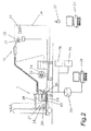
図2は、本発明に従って構成された溶接装置1を示す。このために、動作状態の検出のための手段、例えば、温度センサ31と、溶接ワイヤ13用の供給ドラム14のモニタのためのセンサ32と、溶接場所の視覚的検出のためのカメラ33とが設けられ、これらは適切なライン34を経由してコンピュータユニット29に接続される。メモリユニット35は、コンピュータユニット29に接続または一体化され、検出された動作状態を処理するための規則および処理された動作状態と比較するための状態を保存する。本発明に従えば、検出された動作状態、例えば温度、ワイヤ供給などが処理され、例えば、平均値を求めたり、メモリユニット35に預けられた所定の値と比較され、特別な状態の発生に割り当てられたメッセージが外部の受信器37に送信される。メモリユニット35に保存されたデータの変化の入力は、例えば、ターミナル38を経由して実行してもよい。メッセージは、個々の受信器37によって直ちに読み取り可能になように、テキスト形式で利用可能であることが好ましい。テキストメッセージから音響信号への変換および遠距離通信やラジオネットワークを経由した当該送信も想定できる。好ましい手法は、溶接装置1の識別番号が送信メッセージとともに送信され、受信器が該メッセージを正しい溶接装置1に直ちに割り当てるのを可能にする。識別装置39は、コンピュータユニット29に接続可能であり、識別目的のために設けられる、溶接装置1において、例えば、マイクロプロセッサなどで構成されたユニット40は、検出された動作状態の前処理のために設けてもよい。
FIG. 2 shows a welding apparatus 1 constructed in accordance with the present invention. For this purpose, means for detecting the operating state, for example a
図3は、2つの溶接装置1を備える生産工場を示す。溶接装置1は、適切なインタフェース41、例えば、標準化されたOPC(object link embedding for process control)インタフェースを経由して、定義されたメッセージを選択された受信器へ送信するためのユニット36に接続される。溶接装置1の溶接トーチ10は、適切なロボットアーム43によって、ワーク品、例えば、自動車のボディへ向けて移動する。ロボットアーム43は、ネットワーク化された制御コンピュータ42によって制御され調整される。本発明に係る送信ユニット36は、例えば、故障発生の際に、割り当てられたメッセージ、例えば「溶接ワイヤコイル無し」を、選択された受信器、例えば、保管庫に対して、選択された方法、例えば、携帯電話でのSMSによって送信することになる。外部の受信器37を運んで読み取りを行う人間は、エラーまたは検出された動作状態に直ちに反応して、例えば、溶接装置1に取り付けるべき新しいワイヤコイルを発注することができる。こうして貴重な時間が節約され、連続的な生産サイクルが保証される。適切な初期設定(default)によって、メッセージは、様々な媒体を介して様々な受信器に送信可能である。
FIG. 3 shows a production plant with two welding devices 1. The welding apparatus 1 is connected to a
次に、溶接手順における幾つかの検出された動作状態、割り当てられたメッセージ、割り当てられた受信器、割り当てられた送信方法を例として示す。 Next, some detected operating states, assigned messages, assigned receivers, assigned transmission methods in the welding procedure are shown as examples.
検出された動作状態:「溶接ワイヤの終わり」
メッセージ「溶接ワイヤを発注」、在庫管理者宛て、ファクシミリ経由
メッセージ「溶接ワイヤを供給」、倉庫オペレータ宛て、SMS経由
メッセージ「溶接ワイヤを変更」、操作者宛て、電話経由
Detected operating state: "End of welding wire"
Message “Purchase welding wire”, to inventory manager, via facsimile Message “supply welding wire”, to warehouse operator, via SMS Message “change welding wire”, to operator, via phone
検出された動作状態:「モータ過電流」
メッセージ「コア汚染」、操作者宛て、電話経由
Detected operating state: “Motor overcurrent”
Message "Core contamination", addressed to operator, via phone
当然ながら、メッセージを幾つかの別々の受信器に別々の方法で同時に送信することも可能であり、特別な動作状態の発生の際には、幾つかのメッセージを幾つかの別々の受信器に送信することも可能である。 Of course, it is also possible to send messages to several separate receivers simultaneously in different ways, and in the event of a special operating condition, several messages are sent to several separate receivers. It is also possible to transmit.
Claims (26)
検出された動作状態は、保存された規則に従って処理され、保存された状態と比較され、そして、比較結果の関数として自動的に割り当てられたメッセージが外部の受信器に送信されることを特徴とする方法。 A method of operating a welding apparatus in which controlled or regulated power is supplied to a welding torch or electrode and an operating state is detected, transmitted to a computer unit and processed by the computer unit at least during a welding procedure. And
The detected operating state is processed according to stored rules, compared with the stored state, and automatically assigned messages as a function of the comparison result are sent to an external receiver. how to.
動作状態を処理するための規則および処理された動作状態を比較するための状態についての保存のための少なくとも1つの装置(35)と、コンピュータユニット(29)に接続され、外部の受信器(37)へのメッセージ送信のための少なくとも1つの装置(36)とを備え、
比較結果の関数として割り当てられたメッセージが、前記外部の受信器(37)へ自動的に送信可能であることを特徴とする溶接装置。 Preferably comprising an energy source (2) controlled or regulated by a control device (4), in particular a power source, and at least one welding torch (10) or electrode, in particular a welding wire, and at least one for detecting the operating state. Welding apparatus comprising one device and at least one computer unit (29) connected to at least one detection device and provided for processing said operating state,
At least one device (35) for storage of rules for processing operating states and states for comparing processed operating states, and an external receiver (37) connected to the computer unit (29) And at least one device (36) for sending messages to
A welding apparatus characterized in that a message assigned as a function of the comparison result can be automatically transmitted to the external receiver (37).
Applications Claiming Priority (2)
| Application Number | Priority Date | Filing Date | Title |
|---|---|---|---|
| AT10022002 | 2002-07-04 | ||
| PCT/AT2003/000124 WO2004004960A1 (en) | 2002-07-04 | 2003-04-30 | Method for operating a welding device, and one such welding device |
Publications (2)
| Publication Number | Publication Date |
|---|---|
| JP2005535456A true JP2005535456A (en) | 2005-11-24 |
| JP2005535456A5 JP2005535456A5 (en) | 2006-01-12 |
Family
ID=30004245
Family Applications (1)
| Application Number | Title | Priority Date | Filing Date |
|---|---|---|---|
| JP2004518246A Pending JP2005535456A (en) | 2002-07-04 | 2003-04-30 | Method of operating welding apparatus and welding apparatus |
Country Status (6)
| Country | Link |
|---|---|
| US (1) | US20050252898A1 (en) |
| EP (1) | EP1519807A1 (en) |
| JP (1) | JP2005535456A (en) |
| CN (1) | CN100386172C (en) |
| AU (1) | AU2003229340A1 (en) |
| WO (1) | WO2004004960A1 (en) |
Cited By (2)
| Publication number | Priority date | Publication date | Assignee | Title |
|---|---|---|---|---|
| JP2007527322A (en) * | 2004-02-09 | 2007-09-27 | リンカーン グローバル インコーポレーテッド | System and method for providing automatic welding notification |
| JP2016038709A (en) * | 2014-08-07 | 2016-03-22 | Jfeエンジニアリング株式会社 | Welding system and welding equipment |
Families Citing this family (26)
| Publication number | Priority date | Publication date | Assignee | Title |
|---|---|---|---|---|
| US6795778B2 (en) * | 2001-05-24 | 2004-09-21 | Lincoln Global, Inc. | System and method for facilitating welding system diagnostics |
| CN101193723B (en) * | 2004-02-09 | 2011-09-07 | 林肯环球股份有限公司 | System and method providing automated welding notification |
| US7294808B2 (en) | 2004-03-15 | 2007-11-13 | Lincoln Global, Inc. | Remote wire feeder |
| WO2005110658A2 (en) | 2004-05-14 | 2005-11-24 | Fronius International Gmbh | Method for operation of a welding unit welding unit and welding torch for such a welding unit |
| US20060070987A1 (en) * | 2004-09-30 | 2006-04-06 | Lincoln Global, Inc. | Monitoring device for welding wire supply |
| AT502326B1 (en) * | 2005-09-09 | 2009-07-15 | Fronius Int Gmbh | REMOTE ACCESS UNIT AND COMMUNICATION METHOD FOR MANAGING WELDING DEVICES |
| US20080078811A1 (en) * | 2006-09-15 | 2008-04-03 | The Lincoln Electric Company | Weld data acquisition |
| US20090212027A1 (en) * | 2008-02-21 | 2009-08-27 | Hypertherm, Inc. | Binary Signal Detection |
| US8144193B2 (en) * | 2009-02-09 | 2012-03-27 | Recognition Robotics, Inc. | Work piece tracking system and method |
| US20110202168A1 (en) * | 2010-02-12 | 2011-08-18 | Illinois Tool Works Inc. | Welding-Type System With Embedded Database |
| US8842191B2 (en) | 2010-06-03 | 2014-09-23 | Recognition Robotics, Inc. | System and method for visual recognition |
| US9993891B2 (en) | 2010-07-14 | 2018-06-12 | Illinois Tool Works Inc. | Welding parameter control via welder motion or position monitoring |
| US8688815B2 (en) * | 2010-10-29 | 2014-04-01 | Lincoln Global, Inc. | System and method for welder with help request functionality |
| US10259065B2 (en) * | 2011-07-11 | 2019-04-16 | General Electric Company | Dual-torch welding system |
| US10507542B2 (en) * | 2012-05-31 | 2019-12-17 | Illinois Tool Works Inc. | System and method for pairing welding devices |
| US9665093B2 (en) | 2013-03-15 | 2017-05-30 | Illinois Tool Works Inc. | Welding resource performance comparison system and method |
| JP6168701B2 (en) * | 2014-03-04 | 2017-07-26 | 株式会社神戸製鋼所 | TIG welding system, program, and TIG welding method |
| DE102014104227B4 (en) | 2014-03-26 | 2016-08-18 | Lorch Schweißtechnik GmbH | PROCESS FOR EXTENDING THE FUNCTION OF AN ELECTRIC WELDING DEVICE AND WELDING DEVICE FOR CARRYING OUT SAID METHOD |
| US10987762B2 (en) | 2014-09-30 | 2021-04-27 | Illinois Tool Works Inc. | Armband based systems and methods for controlling welding equipment using gestures and like motions |
| US10201868B2 (en) | 2014-09-30 | 2019-02-12 | Illinois Tool Works Inc. | Systems and methods for gesture control of a welding system |
| CN105834560B (en) * | 2016-05-05 | 2018-06-22 | 苏州金品线材科技有限公司 | A kind of submerged-arc welding production line and its production technology |
| CN105945444A (en) * | 2016-06-29 | 2016-09-21 | 中车青岛四方机车车辆股份有限公司 | Real-time monitoring method and system for incomplete welding |
| US10682721B2 (en) | 2016-07-14 | 2020-06-16 | Lincoln Global, Inc. | Method and system for welding with temperature detector |
| PL3632189T3 (en) | 2017-05-25 | 2024-03-25 | Oerlikon Metco (Us) Inc. | Plasma gun diagnostics apparatus and method |
| CN111299908A (en) * | 2018-12-11 | 2020-06-19 | 福建普天亿智科技有限公司 | Novel digital wire feeder |
| US11311958B1 (en) * | 2019-05-13 | 2022-04-26 | Airgas, Inc. | Digital welding and cutting efficiency analysis, process evaluation and response feedback system for process optimization |
Family Cites Families (10)
| Publication number | Priority date | Publication date | Assignee | Title |
|---|---|---|---|---|
| AT411880B (en) * | 1998-01-13 | 2004-07-26 | Fronius Int Gmbh | CONTROL DEVICE FOR A WELDING MACHINE |
| CN1113723C (en) * | 1999-04-02 | 2003-07-09 | 北京工业大学 | Fuzzy control method for cooperating type CO2 welding circuit-shorting transition and welding machine thereof |
| AT501741B1 (en) * | 1999-08-16 | 2006-11-15 | Fronius Int Gmbh | WELDING DEVICE WITH COMMUNICATION INTERFACE AND METHOD FOR OPERATING THE WELDING DEVICE |
| DE10015487A1 (en) * | 2000-03-30 | 2001-10-04 | Wolfgang Schroeter | Electronic address registration and routing system e.g. for accessing Internet through mobile phones, recognizes scanned address information based on specific parameters and predefined actions |
| US6670810B2 (en) * | 2000-04-25 | 2003-12-30 | Airak, Inc. | System and method for distributed monitoring of surroundings using telemetry of data from remote sensors |
| AU2001277844A1 (en) * | 2000-04-25 | 2001-11-07 | Airak, Inc. | System and method for distributed monitoring using remote sensors |
| AT412389B (en) * | 2000-12-11 | 2005-02-25 | Fronius Int Gmbh | SYSTEM FOR IMPLEMENTING A WELDING PROCESS |
| US6795778B2 (en) * | 2001-05-24 | 2004-09-21 | Lincoln Global, Inc. | System and method for facilitating welding system diagnostics |
| US6697701B2 (en) * | 2001-08-09 | 2004-02-24 | Lincoln Global, Inc. | Welding system and methodology providing multiplexed cell control interface |
| US7574172B2 (en) * | 2001-09-25 | 2009-08-11 | Lincoln Global | System and method to facilitate wireless wide area communication in a welding environment |
-
2003
- 2003-04-30 US US10/518,573 patent/US20050252898A1/en not_active Abandoned
- 2003-04-30 JP JP2004518246A patent/JP2005535456A/en active Pending
- 2003-04-30 EP EP03722035A patent/EP1519807A1/en not_active Withdrawn
- 2003-04-30 CN CNB038156822A patent/CN100386172C/en not_active Expired - Fee Related
- 2003-04-30 AU AU2003229340A patent/AU2003229340A1/en not_active Abandoned
- 2003-04-30 WO PCT/AT2003/000124 patent/WO2004004960A1/en active Application Filing
Cited By (2)
| Publication number | Priority date | Publication date | Assignee | Title |
|---|---|---|---|---|
| JP2007527322A (en) * | 2004-02-09 | 2007-09-27 | リンカーン グローバル インコーポレーテッド | System and method for providing automatic welding notification |
| JP2016038709A (en) * | 2014-08-07 | 2016-03-22 | Jfeエンジニアリング株式会社 | Welding system and welding equipment |
Also Published As
| Publication number | Publication date |
|---|---|
| EP1519807A1 (en) | 2005-04-06 |
| CN100386172C (en) | 2008-05-07 |
| US20050252898A1 (en) | 2005-11-17 |
| CN1665634A (en) | 2005-09-07 |
| WO2004004960A1 (en) | 2004-01-15 |
| AU2003229340A1 (en) | 2004-01-23 |
Similar Documents
| Publication | Publication Date | Title |
|---|---|---|
| JP2005535456A (en) | Method of operating welding apparatus and welding apparatus | |
| US6797921B1 (en) | Welding unit equipped with a communications interface and method for operating the welding unit | |
| US20210283704A1 (en) | Automatic weld arc monitoring system | |
| KR101986276B1 (en) | Weld cell systems, cable and methods for identifying a weld cable | |
| CN107787578B (en) | Master controller for telematics integration | |
| CN104395031B (en) | System and method for detecting welding and cutting parameter | |
| US7853435B2 (en) | System and method for facilitating welding system diagnostics | |
| US20140074286A1 (en) | System to monitor/analyze robot related information and display on a smart device | |
| JP2005535456A5 (en) | ||
| CN100475424C (en) | Backup controller for welding-type device remote controller and method of use | |
| AU2002309655A1 (en) | System and method for facilitating welding system diagnostics | |
| MX2014012290A (en) | System flor and method of pairing welding devices wherein the pairing includes|a change in welding power and/or welding consumables. | |
| US20200361016A1 (en) | System and method for monitoring resistance in a wire feed device | |
| CN107921566B (en) | Sensor module for a manufacturing tool | |
| EP3505287A1 (en) | A welding torch, a system with such a welding torch and a method for controlling such a system | |
| US20220075003A1 (en) | External connector and sensor unit for welding equipment | |
| CN108501388B (en) | Electric fusion welding monitor and use scheme thereof | |
| CN111511496A (en) | Hardware-based reporting module and system for using reusable and reconfigurable reporter modules in welding-type devices | |
| CN218139957U (en) | Automatic welding system for polyethylene electric melting pipe fittings based on 5G communication | |
| JP2023092983A (en) | Welding torch and welding device | |
| KR20040098218A (en) | System for sending and repairing failure information |
Legal Events
| Date | Code | Title | Description |
|---|---|---|---|
| A521 | Request for written amendment filed |
Free format text: JAPANESE INTERMEDIATE CODE: A523 Effective date: 20051108 |
|
| A621 | Written request for application examination |
Free format text: JAPANESE INTERMEDIATE CODE: A621 Effective date: 20051108 |
|
| RD03 | Notification of appointment of power of attorney |
Free format text: JAPANESE INTERMEDIATE CODE: A7423 Effective date: 20070726 |
|
| A131 | Notification of reasons for refusal |
Free format text: JAPANESE INTERMEDIATE CODE: A131 Effective date: 20080527 |
|
| A02 | Decision of refusal |
Free format text: JAPANESE INTERMEDIATE CODE: A02 Effective date: 20090303 |