JP2005534812A - Method for coating the surface of a metal material and apparatus for carrying out the method - Google Patents
Method for coating the surface of a metal material and apparatus for carrying out the method Download PDFInfo
- Publication number
- JP2005534812A JP2005534812A JP2004526971A JP2004526971A JP2005534812A JP 2005534812 A JP2005534812 A JP 2005534812A JP 2004526971 A JP2004526971 A JP 2004526971A JP 2004526971 A JP2004526971 A JP 2004526971A JP 2005534812 A JP2005534812 A JP 2005534812A
- Authority
- JP
- Japan
- Prior art keywords
- coating
- metal
- strip
- layer
- produced
- Prior art date
- Legal status (The legal status is an assumption and is not a legal conclusion. Google has not performed a legal analysis and makes no representation as to the accuracy of the status listed.)
- Pending
Links
Images


Classifications
-
- C—CHEMISTRY; METALLURGY
- C23—COATING METALLIC MATERIAL; COATING MATERIAL WITH METALLIC MATERIAL; CHEMICAL SURFACE TREATMENT; DIFFUSION TREATMENT OF METALLIC MATERIAL; COATING BY VACUUM EVAPORATION, BY SPUTTERING, BY ION IMPLANTATION OR BY CHEMICAL VAPOUR DEPOSITION, IN GENERAL; INHIBITING CORROSION OF METALLIC MATERIAL OR INCRUSTATION IN GENERAL
- C23C—COATING METALLIC MATERIAL; COATING MATERIAL WITH METALLIC MATERIAL; SURFACE TREATMENT OF METALLIC MATERIAL BY DIFFUSION INTO THE SURFACE, BY CHEMICAL CONVERSION OR SUBSTITUTION; COATING BY VACUUM EVAPORATION, BY SPUTTERING, BY ION IMPLANTATION OR BY CHEMICAL VAPOUR DEPOSITION, IN GENERAL
- C23C28/00—Coating for obtaining at least two superposed coatings either by methods not provided for in a single one of groups C23C2/00 - C23C26/00 or by combinations of methods provided for in subclasses C23C and C25C or C25D
- C23C28/30—Coatings combining at least one metallic layer and at least one inorganic non-metallic layer
- C23C28/32—Coatings combining at least one metallic layer and at least one inorganic non-metallic layer including at least one pure metallic layer
- C23C28/322—Coatings combining at least one metallic layer and at least one inorganic non-metallic layer including at least one pure metallic layer only coatings of metal elements only
-
- C—CHEMISTRY; METALLURGY
- C23—COATING METALLIC MATERIAL; COATING MATERIAL WITH METALLIC MATERIAL; CHEMICAL SURFACE TREATMENT; DIFFUSION TREATMENT OF METALLIC MATERIAL; COATING BY VACUUM EVAPORATION, BY SPUTTERING, BY ION IMPLANTATION OR BY CHEMICAL VAPOUR DEPOSITION, IN GENERAL; INHIBITING CORROSION OF METALLIC MATERIAL OR INCRUSTATION IN GENERAL
- C23C—COATING METALLIC MATERIAL; COATING MATERIAL WITH METALLIC MATERIAL; SURFACE TREATMENT OF METALLIC MATERIAL BY DIFFUSION INTO THE SURFACE, BY CHEMICAL CONVERSION OR SUBSTITUTION; COATING BY VACUUM EVAPORATION, BY SPUTTERING, BY ION IMPLANTATION OR BY CHEMICAL VAPOUR DEPOSITION, IN GENERAL
- C23C28/00—Coating for obtaining at least two superposed coatings either by methods not provided for in a single one of groups C23C2/00 - C23C26/00 or by combinations of methods provided for in subclasses C23C and C25C or C25D
- C23C28/30—Coatings combining at least one metallic layer and at least one inorganic non-metallic layer
- C23C28/32—Coatings combining at least one metallic layer and at least one inorganic non-metallic layer including at least one pure metallic layer
- C23C28/321—Coatings combining at least one metallic layer and at least one inorganic non-metallic layer including at least one pure metallic layer with at least one metal alloy layer
-
- C—CHEMISTRY; METALLURGY
- C23—COATING METALLIC MATERIAL; COATING MATERIAL WITH METALLIC MATERIAL; CHEMICAL SURFACE TREATMENT; DIFFUSION TREATMENT OF METALLIC MATERIAL; COATING BY VACUUM EVAPORATION, BY SPUTTERING, BY ION IMPLANTATION OR BY CHEMICAL VAPOUR DEPOSITION, IN GENERAL; INHIBITING CORROSION OF METALLIC MATERIAL OR INCRUSTATION IN GENERAL
- C23C—COATING METALLIC MATERIAL; COATING MATERIAL WITH METALLIC MATERIAL; SURFACE TREATMENT OF METALLIC MATERIAL BY DIFFUSION INTO THE SURFACE, BY CHEMICAL CONVERSION OR SUBSTITUTION; COATING BY VACUUM EVAPORATION, BY SPUTTERING, BY ION IMPLANTATION OR BY CHEMICAL VAPOUR DEPOSITION, IN GENERAL
- C23C28/00—Coating for obtaining at least two superposed coatings either by methods not provided for in a single one of groups C23C2/00 - C23C26/00 or by combinations of methods provided for in subclasses C23C and C25C or C25D
- C23C28/30—Coatings combining at least one metallic layer and at least one inorganic non-metallic layer
- C23C28/34—Coatings combining at least one metallic layer and at least one inorganic non-metallic layer including at least one inorganic non-metallic material layer, e.g. metal carbide, nitride, boride, silicide layer and their mixtures, enamels, phosphates and sulphates
- C23C28/345—Coatings combining at least one metallic layer and at least one inorganic non-metallic layer including at least one inorganic non-metallic material layer, e.g. metal carbide, nitride, boride, silicide layer and their mixtures, enamels, phosphates and sulphates with at least one oxide layer
- C23C28/3455—Coatings combining at least one metallic layer and at least one inorganic non-metallic layer including at least one inorganic non-metallic material layer, e.g. metal carbide, nitride, boride, silicide layer and their mixtures, enamels, phosphates and sulphates with at least one oxide layer with a refractory ceramic layer, e.g. refractory metal oxide, ZrO2, rare earth oxides or a thermal barrier system comprising at least one refractory oxide layer
Abstract
本発明は、結晶構造を有する金属材料の表面を被覆する方法に関する。本発明の方法は、融点Tfおよび2.5μ以下の厚みを有する金属層または金属合金層により前記材料の第1被覆を製造すること、前記第1被覆層を、その層が0.8Tf〜Tfの温度に加熱されるように急速加熱により加熱すること、1μm以下の厚みを有する第2の金属または金属合金層を製造することにある。前記方法を実施するための装置および上述したように被覆された金属材料もまた開示されている。The present invention relates to a method for coating a surface of a metal material having a crystal structure. The method of the present invention comprises producing a first coating of the material with a metal layer or metal alloy layer having a melting point T f and a thickness of 2.5 μm or less, wherein the first coating layer is 0.8 T f be heated by rapid heating to be heated to a temperature of through T f, it is to produce a second metal or metal alloy layer having a thickness of less than 1 [mu] m. An apparatus for carrying out the method and a metallic material coated as described above are also disclosed.
Description
本発明は、金属表面の被覆に関する。さらに詳しくは、本発明は、材料に三次元視覚効果を与えることを意図した、金属材料表面を被覆するための加工作業に関する。 The present invention relates to coating metal surfaces. More particularly, the present invention relates to a processing operation for coating a metal material surface intended to give the material a three-dimensional visual effect.
この種の視覚効果は、高度にコントラストの付いた光の干渉を記録することができる感光性媒体に、2本のレーザビームにより画像を記録および再生することにより製造されるホログラムを使用して、達成することができる。この種の媒体は、例えば、熱可塑性フィルム、感光性ポリマー、感光性フィルムなどである。 This type of visual effect uses a hologram produced by recording and reproducing an image with two laser beams on a photosensitive medium capable of recording highly contrasted light interference, Can be achieved. Such media are, for example, thermoplastic films, photosensitive polymers, photosensitive films and the like.
金属表面に三次元視覚効果を生み出すために、接着剤または同時圧延(colaminage)により、上述した種類の感光性媒体を表面に貼り付けること以外の方法は知られていない。鉄鋼またはアルミニウムの金属パッケージの装飾では、この技法が好ましく使用されているが、感光性媒体を提供するのに外部供給業者の関与を必要とするという、金属企業にとって不利な点がある。さらに、接着剤または同時圧延の後でパッケージが受ける加工およびハンドリング作業の間に、媒体がパッケージから分離されたり、損傷を受けたりする危険がある。 In order to produce a three-dimensional visual effect on a metal surface, no method is known other than applying a photosensitive medium of the above-mentioned type to the surface by means of an adhesive or a co-rollage. Although this technique is preferably used in the decoration of steel or aluminum metal packages, there are disadvantages to metal companies that require the involvement of external suppliers to provide the photosensitive media. Furthermore, there is a risk that the media may be separated from the package or damaged during processing and handling operations that the package undergoes after adhesive or co-rolling.
本発明の目的は、表面に貼り付けられなければならない感光性媒体を使用することなく、金属材料の表面に三次元視覚効果を生じさせる方法を提供することである。 It is an object of the present invention to provide a method for producing a three-dimensional visual effect on the surface of a metallic material without using a photosensitive medium that must be attached to the surface.
この目的のために、本発明の主題は、
結晶構造を有する金属材料の表面を被覆する方法であって、該材料はTfに等しい融点および2.5μm以下の厚みを有する金属または金属合金の層で第一に被覆され、ここで、
第1被覆は、急速加熱手段を使用する熱処理に供して、第1被覆の表面を0.8Tf〜Tfの間の温度にする、
第2被覆は、1μm以下の厚みを有する金属または金属合金からの蒸着である、
ことを特徴とする、方法である。
For this purpose, the subject of the present invention is
A method of coating a surface of a metallic material having a crystalline structure, wherein the material is first coated with a layer of a metal or metal alloy having a melting point equal to T f and a thickness of 2.5 μm or less, wherein
The first coating is subjected to a heat treatment using rapid heating means to bring the surface of the first coating to a temperature between 0.8 Tf and Tf .
The second coating is a vapor deposition from a metal or metal alloy having a thickness of 1 μm or less.
It is the method characterized by this.
本方法の変形形態によれば、第1および第2被覆は700℃以下の融点を有する。 According to a variant of the method, the first and second coatings have a melting point of 700 ° C. or less.
第1および第2被覆は、同一材料から構成され得る。 The first and second coatings can be composed of the same material.
本方法の変形形態によれば、次に、透明な鉱物フィルムが第2被覆上に蒸着される。 According to a variant of the method, a transparent mineral film is then deposited on the second coating.
好ましくは、被覆される金属材料は、炭素鋼、ステンレス鋼、またはアルミニウムまたはそれらの合金の1種であり得る。 Preferably, the metal material to be coated may be carbon steel, stainless steel, or aluminum or one of their alloys.
好ましくは、第1被覆は、電着または物理蒸着法によって製造され得る。 Preferably, the first coating can be produced by electrodeposition or physical vapor deposition.
好ましくは、急速加熱手段は、赤外線加熱装置、誘導加熱装置、非反応性気体によるプラズマ放電装置または非反応性気体によるイオン衝撃装置であり得る。 Preferably, the rapid heating means may be an infrared heating device, an induction heating device, a plasma discharge device using a non-reactive gas, or an ion bombardment device using a non-reactive gas.
好ましくは、第2被覆は、電着または物理蒸着法によって製造され得る。 Preferably, the second coating can be produced by electrodeposition or physical vapor deposition.
透明な鉱物フィルムは、反応性プラズマ補助化学蒸着法によって蒸着され得る。 Transparent mineral films can be deposited by reactive plasma assisted chemical vapor deposition.
第1および第2被覆は、それぞれ錫および/またはアルミニウムによって構成され得る。 The first and second coatings can be composed of tin and / or aluminum, respectively.
鉱物フィルムは、好ましくは、オーステナイト系ステンレス鋼、クロム、チタン、ケイ素、亜鉛、錫の酸化物から選択された金属酸化物または金属酸化物の混合物である。 The mineral film is preferably a metal oxide or a mixture of metal oxides selected from austenitic stainless steel, chromium, titanium, silicon, zinc, tin oxides.
金属材料は、移動ストリップの形状をとることができ、移動ストリップの経路上に連続的に配置された装置により、この方法のさまざまな工程が連続的に実行され得る。 The metallic material can take the form of a moving strip, and the various steps of the method can be carried out continuously by means of a device arranged continuously on the path of the moving strip.
本発明はまた、ストリップを移動させるための手段およびストリップの経路上に連続的に配置された、
Tfに等しい融点を有する金属または金属合金の層でストリップを被覆する第1手段、
前記層の表面を、0.8Tf〜Tfの間の温度にすることができるストリップを急速加熱する手段、および
金属または金属合金の層でストリップを被覆する第2手段、
を備えていることを特徴とするストリップ形状の金属材料を被覆する装置に関する。
The present invention also comprises means for moving the strip and continuously disposed on the path of the strip,
A first means for coating the strip with a layer of metal or metal alloy having a melting point equal to T f ;
Means for rapidly heating the strip whose surface can be brought to a temperature between 0.8 Tf and Tf ; and second means for coating the strip with a layer of metal or metal alloy;
The present invention relates to an apparatus for coating a strip-shaped metal material.
前記装置は、金属または金属合金の層で前記ストリップを被覆する第2手段の下方に、透明な鉱物フィルムで前記ストリップを被覆する手段を備えることができる。 The apparatus may comprise means for coating the strip with a transparent mineral film below the second means for coating the strip with a layer of metal or metal alloy.
本発明はまた、三次元視覚効果を有する金属被覆を、金属表面の少なくとも1つの面上に備え、前記被覆は前記金属材料の表面に直接形成され、特に前述の方法によって実施されることを特徴とする、金属材料に関する。 The invention also comprises a metal coating having a three-dimensional visual effect on at least one surface of the metal surface, wherein the coating is formed directly on the surface of the metal material, in particular carried out by the method described above. It relates to a metal material.
いずれ理解されるように、本発明は、金属材料自体の表面を加工する一連の作業を利用して所望の三次元視覚効果を作りだすことにある。このやり方で、金属材料から分離され得ない、かつ、基材を製造した金属企業によって製造され得る、多層被覆が製造される。この被覆には、その美的品質に加えて、いくつかの技術上の利点があり、金属材料生産業者が装飾工程を完全に支配することができる。 As will be appreciated, the present invention resides in creating a desired three-dimensional visual effect using a series of operations that process the surface of the metal material itself. In this way, a multilayer coating is produced that cannot be separated from the metal material and that can be produced by the metal company that produced the substrate. In addition to its aesthetic qualities, this coating has several technical advantages that allow metal material producers to completely control the decoration process.
本発明は、本発明による方法の種々の変形形態により製造されたさまざまな被覆の外観を示す添付の図面1〜6に関して与えられた、以下の記述を読むことにより、よりよく理解されるはずである。 The invention should be better understood by reading the following description, given with reference to the accompanying drawings 1 to 6, which show the appearance of various coatings produced by various variants of the method according to the invention. is there.
出発材料は、炭素鋼、ステンレス鋼、アルミニウムまたはそれらの合金の1種などの金属材料である。その材料は、例えば、プレートまたは巻いたストリップ形状である。この最後の場合は、ストリップを巻き戻して、加工作業の種々の工程が実施され得る装置を、ストリップの経路上に連続的に配置されている設備の中を連続的に移動させることによって、後で説明されるはずの加工作業を実施することが可能である。所望の美的効果を達成するために、基板として使用されている金属材料は結晶構造を有することが必要である。 The starting material is a metallic material such as carbon steel, stainless steel, aluminum or one of their alloys. The material is, for example, in the form of a plate or a rolled strip. In this last case, the strip is rewound and subsequently moved by moving the equipment in which the various steps of the processing operation can be carried out in equipment continuously arranged on the path of the strip. It is possible to carry out a machining operation that should be described in. In order to achieve the desired aesthetic effect, the metal material used as the substrate needs to have a crystalline structure.
蒸着を実施する前に、任意の表面汚染を除去するために、それ自体で知られているやり方で材料表面が調整される。 Prior to performing the deposition, the material surface is conditioned in a manner known per se in order to remove any surface contamination.
この方法の第1工程は、好ましくは、700℃以下のオーダーの低い融点Tfを有する金属元素(例えば、錫またはアルミニウム)または金属合金によって構成される第1被覆を蒸着することである。この被覆は、2.5μm以下の厚みを有していなければならない。 The first step of the method is preferably to deposit a first coating composed of a metal element (for example tin or aluminum) or a metal alloy having a low melting point T f on the order of 700 ° C. or less. This coating must have a thickness of 2.5 μm or less.
有利にも、この被覆は電着法または物理蒸着法により製造される。使用され得る物理蒸着法には、真空蒸着、マグネトロンスパッタリング、イオンプレーティング、自己誘導イオンプレーティングを含む従来から知られている方法が含まれる。 Advantageously, this coating is produced by electrodeposition or physical vapor deposition. Physical vapor deposition methods that can be used include conventionally known methods including vacuum vapor deposition, magnetron sputtering, ion plating, self-induced ion plating.
この方法の第2工程は、赤外線ランプ、インダクタ、プラズマ放電作業、または不活性ガスなどの非反応性気体によるイオン衝撃などの急速加熱手段を使用して、第1被覆上で実施される熱加工作業である。この熱加工では、第1被覆の表面を0.8Tf〜Tfの間の温度にしなければならない。100m/mnのオーダの速度で移動するストリップ上で実施されるのに適合した速度で実施するために、Tfは700℃以下が好ましい。 The second step of the method involves thermal processing performed on the first coating using rapid heating means such as an infrared lamp, inductor, plasma discharge operation, or ion bombardment with a non-reactive gas such as an inert gas. Work. In this thermal processing, the surface of the first coating must be brought to a temperature between 0.8 Tf and Tf . To carry out at a speed adapted to be carried out on a strip moving at a speed on the order of 100 m / mn, T f is preferably below 700 ° C.
この方法の第3工程は、第1被覆の材料と同一であることもあり、ないこともある金属元素または合金から、第2被覆の蒸着をすることである。この被覆は、1μmを超えない厚みを有しなければならない。これは、第1被覆と同じ方法を用いて製造され得る。 The third step of the method is to deposit the second coating from a metal element or alloy that may or may not be the same as the material of the first coating. This coating must have a thickness not exceeding 1 μm. This can be manufactured using the same method as the first coating.
好ましくは(しかし、必ずしも必要ではない)、この方法は、第2金属被覆上に透明な鉱物フィルムを蒸着することからなる第4工程を含むことができる。オーステナイト系ステンレス鋼、クロム、チタン、ケイ素、亜鉛、錫(非制限的な一覧である)の酸化物およびそれらの混合物などの材料が、特に適切である。この透明な鉱物の蒸着は、この目的に適した、公知のどの手段によっても実施され得るものであり、反応性プラズマ補助化学蒸着法は特に適切である。このフィルムが1μm以下の厚みを有する場合は、鉱物フィルムの干渉効果により、着色被覆が製造され得る。蒸着された材料の屈折率に応じて、緑、黄、青、紫および赤の色がこのやり方で容易に得られる。一般に、この透明フィルムは、この方法の最初の3工程の後で製造される三次元の外観を有する模様に対して、さらに深みのある外観を与える。 Preferably (but not necessarily), the method can include a fourth step consisting of depositing a transparent mineral film on the second metallization. Materials such as austenitic stainless steel, chromium, titanium, silicon, zinc, tin (which is a non-limiting list) oxides and mixtures thereof are particularly suitable. This transparent mineral deposition can be carried out by any known means suitable for this purpose, and reactive plasma assisted chemical vapor deposition is particularly suitable. When this film has a thickness of 1 μm or less, a colored coating can be produced due to the interference effect of the mineral film. Depending on the refractive index of the deposited material, green, yellow, blue, purple and red colors are easily obtained in this manner. In general, this transparent film gives a deeper appearance to patterns with a three-dimensional appearance produced after the first three steps of the method.
上述のように、基板表面上に模様が現れるためには、基板が結晶構造を有することが必要である。金属蒸着物の凝固模様の核形成は、基板が結晶構造を有する場合にのみ存在する、基板表面の優先部位に基づいて引き起こされる。 As described above, the substrate needs to have a crystal structure in order for the pattern to appear on the substrate surface. Nucleation of the solidified pattern of the metal deposit is triggered based on the preferential sites on the substrate surface that exist only when the substrate has a crystalline structure.
生じる模様のサイズは、この方法の第2工程で使用されたエネルギーの量および被覆の厚みによって決まり、このエネルギーの量および/またはこの厚みが大きくなるにつれて、この模様は大きくなるはずである。この方法の第1工程において、低融点(700℃以下)の金属または合金を被覆材料として使用することにより、第2工程において前記被覆の金属転移が非常に短時間で実施され得る。これまでに述べた加熱方法により、可能な限りの最短時間で、必要なエネルギーが供給され得る。 The size of the resulting pattern depends on the amount of energy used in the second step of the method and the thickness of the coating, and as this amount of energy and / or this thickness increases, the pattern should increase. By using a low melting point (700 ° C. or lower) metal or alloy as the coating material in the first step of the method, the metal transition of the coating can be performed in a very short time in the second step. With the heating methods described so far, the necessary energy can be supplied in the shortest possible time.
金属製品に貼り付けられた感光性媒体を使用して三次元視覚効果を作りだすことと比較して、本発明による方法はいくつかの利点を有する。上述のように、本発明によれば、金属製品生産業者が本方法を完全に支配することができる。この場合は、三次元視覚効果を作りだす被覆は媒体の不可欠な部分であるので、引き続き行われる加工および取り扱い作業の間に、被覆が分離する危険はない。さらに、最も特別には、この方法が4工程ですべて使用される場合は、このやり方で製造された被覆は、化粧品による腐食に対する基板の耐久性を高める。被覆はまた、紫外線放射および温度に対して、より高い耐久性を有する。この被覆は、指紋に対する鋭敏性がより低い。この被覆は、表面硬度が大きく、引っかき傷に対する鋭敏性がより低い。この被覆は洗浄しやすく、保守製品および他の機械的影響に対して効果的に耐える。最後に、使用された被覆金属が適切な場合は(例えば、錫)、この被覆を食料品分野で使用するのに適合したものにするのが可能である。 Compared to using a photosensitive medium affixed to a metal product to create a three-dimensional visual effect, the method according to the invention has several advantages. As mentioned above, according to the present invention, the metal product producer can completely control the method. In this case, the coating that creates the three-dimensional visual effect is an integral part of the media, so there is no danger of the coating separating during subsequent processing and handling operations. Furthermore, most particularly, if this method is used in all four steps, a coating produced in this manner increases the durability of the substrate against corrosion by cosmetics. The coating is also more resistant to ultraviolet radiation and temperature. This coating is less sensitive to fingerprints. This coating has a high surface hardness and is less sensitive to scratches. This coating is easy to clean and effectively withstands maintenance products and other mechanical effects. Finally, if the coating metal used is appropriate (eg, tin), it is possible to make the coating suitable for use in the food sector.
本発明による方法を実施するためのさまざまな実施例を、ここで述べることにする。実施例は、200×200mmで0.7mm厚みの軟鋼シート上で実施される。これらのシートは、給湿手段(超音波で攪拌された溶媒)を使用した通常のやり方で予め脱脂される。これらのシートは、次いで、真空反応器におけるアルゴンプラズマから始まるイオンピクリング(ion pickling)操作を受けるが、この反応器は本発明による方法を実施するためのさまざまな工程で、この後も使用される。 Various examples for carrying out the method according to the invention will now be described. The example is carried out on a mild steel sheet 200 × 200 mm and 0.7 mm thick. These sheets are pre-degreased in the usual way using a moisturizing means (solvent stirred with ultrasound). These sheets are then subjected to an ion pickling operation starting from an argon plasma in a vacuum reactor, which is subsequently used in various steps for carrying out the process according to the invention. The
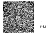
本発明による方法の第1工程においては、シートは、10−3mbar(0.1Pa)の圧力のアルゴン雰囲気下でマグネトロンスパッタリングにより、0.8μmの錫の層によって被覆される。目標電流は0.9Aであり、目標電圧は450Vである。錫の蒸着速度は、0.25μm/分である。 In the first step of the method according to the invention, the sheet is coated with a 0.8 μm layer of tin by magnetron sputtering under an argon atmosphere at a pressure of 10 −3 mbar (0.1 Pa). The target current is 0.9A and the target voltage is 450V. The deposition rate of tin is 0.25 μm / min.
本発明による方法の第2工程においては、シートは、10−3mbar(0.1Pa)の圧力下でアルゴンプラズマを使用して、熱的に加工される。アルゴンのイオンに付与されるエネルギーは400eVであり、シートにより受け止められるイオンの量は、4.7×10²²イオンAr+/m2である。シートは、陰極として設置される。錫の表面は、210℃のオーダーの温度にさせられる。 In the second step of the method according to the invention, the sheet is thermally processed using argon plasma under a pressure of 10 −3 mbar (0.1 Pa). The energy imparted to the argon ions is 400 eV, and the amount of ions received by the sheet is 4.7 × 10 22 ions Ar + / m 2 . The sheet is installed as a cathode. The surface of the tin is brought to a temperature on the order of 210 ° C.
第3工程においては、第1被覆と同じ実験条件下で、マグネトロンスパッタリングを用いて0.4μmの錫の被覆が蒸着される。 In the third step, a 0.4 μm tin coating is deposited using magnetron sputtering under the same experimental conditions as the first coating.
第4工程においては、0.1μmの厚みを有するケイ素の透明なフィルムが、プラズマCVDにより蒸着される。蒸着は、10−3mbar(0.1Pa)の圧力で、ヘキサメチルジシロキサン(HMDSO)と酸素の分圧の比率が1/10である、HMDSOと酸素からなる雰囲気下で実施される。100Wの電力で50kHzの周波数を有する電流が使用される。蒸着速度は、1.0μm/分である。 In the fourth step, a transparent film of silicon having a thickness of 0.1 μm is deposited by plasma CVD. Vapor deposition is performed under an atmosphere of HMDSO and oxygen at a pressure of 10 −3 mbar (0.1 Pa) and a ratio of the partial pressure of hexamethyldisiloxane (HMDSO) to oxygen is 1/10. A current having a frequency of 50 kHz with a power of 100 W is used. The deposition rate is 1.0 μm / min.
この方法を用いて、外観が図1に示されている被覆が製造されるが、その被覆は耐腐食性および耐指紋性を有し、洗浄が用意であり、大きな表面硬度を有する。その被覆は、大きな機械的、化学的および熱的影響に耐えることができる。 Using this method, a coating is produced whose appearance is shown in FIG. 1, which has corrosion resistance and fingerprint resistance, is ready for cleaning and has a high surface hardness. The coating can withstand large mechanical, chemical and thermal effects.
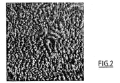
最初の3工程は実施例1と同じ条件下で、鉄鋼シートが被覆される。第4工程の本質的な特徴は、チタンターゲットの反応性マグネトロンスパッタリングにより、酸化チタンの着色フィルムを製造することにある。フィルムの厚みは、0.05μmである。フィルムが製造される条件は、PO2/PAr=0.4であるO2/Ar雰囲気、5.10−3mbar(10.5Pa)の全圧力および1.7kWの電力である。このやり方で、図2に示されている被覆が製造されるが、その被覆は実施例1と同様の性質を有し、加えて二酸化チタンの屈折率(2.5)による青色の外観および二酸化チタンに特有の性質、すなわち、高温における高度の安定性、化学的影響に対する効果的な耐性、および紫外線の存在下で炭素および酸素を含む材料を分解するという、被覆の触媒効果による自己洗浄作用を有する。 In the first three steps, the steel sheet is coated under the same conditions as in Example 1. The essential feature of the fourth step is that a colored film of titanium oxide is produced by reactive magnetron sputtering of a titanium target. The thickness of the film is 0.05 μm. The conditions under which the film is produced are an O 2 / Ar atmosphere where P O 2 / P Ar = 0.4, a total pressure of 5.10 −3 mbar (10.5 Pa) and a power of 1.7 kW. In this way, the coating shown in FIG. 2 is produced, which coating has the same properties as in Example 1, in addition to the blue appearance and the dioxide due to the refractive index of titanium dioxide (2.5). The unique properties of titanium, namely high stability at high temperatures, effective resistance to chemical influences, and self-cleaning action due to the catalytic effect of the coating, which decomposes materials containing carbon and oxygen in the presence of ultraviolet light. Have.
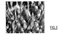
軟鋼シートは、錫の第1被覆の厚みが1.2μmに増大されること、およびこの方法の第2工程の間に錫の第1層によって受け止められるイオンの量が増大されることを除いて、実施例2と同じ条件下で被覆される。この場合、この量は9.4×10²²イオンAr+/m2に達する。錫の表面は、235℃のオーダーの温度にさせられる。結果は、図3において見られる。 The mild steel sheet has the exception that the thickness of the first coating of tin is increased to 1.2 μm and the amount of ions received by the first layer of tin during the second step of the method is increased. And coated under the same conditions as in Example 2. In this case, this amount reaches 9.4 × 10 22 ions Ar + / m 2 . The surface of the tin is brought to a temperature on the order of 235 ° C. The result can be seen in FIG.
軟鋼シートは、実施例3の場合と同じように、第1層によって受け止められるイオンの量が9.4×10²²イオンAr+/m2に増大されること、および二酸化チタンフィルムの厚みが0.08μに増大されること以外は、実施例2と同じ条件下で被覆される。結果は、図4において見られる。 In the mild steel sheet, the amount of ions received by the first layer is increased to 9.4 × 10 22 ions Ar + / m 2 and the thickness of the titanium dioxide film is 0, as in Example 3. It is coated under the same conditions as in Example 2, except that it is increased to 0.08μ. The result can be seen in FIG.
第2加工工程の間に使用されるエネルギーが増加すると、模様のサイズが有意に増大することに注目すべきである。 It should be noted that the pattern size increases significantly as the energy used during the second processing step increases.
シートは、第2工程で2個の赤外線ランプを使用して基板とその基板の錫の第1層を加熱すること、および錫の第2層上に酸化物が蒸着されないことを除いて、実施例1と同じ条件下で被覆される。従って、この方法の最初の3工程のみが実施されるが、これらは所望の三次元視覚効果を作りだすのに必要なものである。錫層の加熱は静的であり、200℃の温度に制御されたランプ形式の炉内で8分間続く。この結果は、図5においてみられる。 The sheet was implemented except that in the second step, two infrared lamps were used to heat the substrate and the first layer of tin on the substrate, and no oxide was deposited on the second layer of tin. It is coated under the same conditions as in Example 1. Thus, only the first three steps of this method are performed, which are necessary to create the desired three-dimensional visual effect. The heating of the tin layer is static and lasts for 8 minutes in a lamp-type furnace controlled at a temperature of 200 ° C. This result is seen in FIG.
200×200mmで厚みが0.2mmの非常に薄い軟鋼シートが、食料品分野で従来から使用されている種類の「ブリキ板」のシートを製造するようなやり方で、錫の電着層によって被覆される。次いで、本発明による方法の第2および第3工程が、実施例2と同じ条件下で実施される。本発明による、場合によって実施されることもある第4加工工程は、実施されない。この結果は、図6において見られる。 A very thin mild steel sheet of 200 × 200 mm and a thickness of 0.2 mm is coated with a tin electrodeposition layer in such a way as to produce a sheet of “tinplate” of the kind conventionally used in the food sector. Is done. The second and third steps of the method according to the invention are then carried out under the same conditions as in Example 2. The fourth machining step according to the invention, which may be carried out in some cases, is not carried out. This result can be seen in FIG.
本発明による方法の第1工程において、10−3mbar(0.1Pa)の気圧のアルゴン雰囲気中でマグネトロンスパッタリングを用いて、0.6μmのアルミニウム層により、シートが被覆される。目標電流は1.8Aであり、目標電圧は355Vである。アルミニウムが蒸着される速度は、0.33μm/分である。 In the first step of the method according to the invention, the sheet is coated with a 0.6 μm aluminum layer using magnetron sputtering in an argon atmosphere at a pressure of 10 −3 mbar (0.1 Pa). The target current is 1.8A and the target voltage is 355V. The rate at which aluminum is deposited is 0.33 μm / min.
本発明による方法の第2工程において、10−3mbar(0.1Pa)の圧力のアルゴンプラズマにより、シートは熱的に処理される。アルゴンイオンに付与されるエネルギーは280eVであり、イオンの量は18.4×10²²イオンAr+/m2である。シートは陰極として設置される。アルミニウムの中で被覆されたシートの表面は、加工作業の最後に615℃の温度にされる。 In the second step of the method according to the invention, the sheet is thermally treated with argon plasma at a pressure of 10 −3 mbar (0.1 Pa). The energy imparted to the argon ions is 280 eV, and the amount of ions is 18.4 × 10 22 ions Ar + / m 2 . The sheet is installed as a cathode. The surface of the sheet coated in aluminum is brought to a temperature of 615 ° C. at the end of the processing operation.
第3工程において、実施例1の第3工程で述べたものと同じ実験条件下で、マグネトロンスパッタリングを使用して、錫の被覆が蒸着される。 In the third step, a tin coating is deposited using magnetron sputtering under the same experimental conditions as described in the third step of Example 1.
これらの製造条件下で、外観が図1の実施例の外観と同一である被覆が製造される。 Under these manufacturing conditions, a coating is produced whose appearance is identical to that of the embodiment of FIG.
最初の2工程は実施例3と同じ条件下で、軟鋼シートが錫によって被覆される。第3工程では、アルミニウムが0.4μmの厚みで蒸着されることを除いて、実施例7の第1工程で記述したものと同じ条件下で、マグネトロンスパッタリングにより、アルミニウム被覆が蒸着される。 In the first two steps, the mild steel sheet is coated with tin under the same conditions as in Example 3. In the third step, an aluminum coating is deposited by magnetron sputtering under the same conditions as described in the first step of Example 7, except that aluminum is deposited with a thickness of 0.4 μm.
これらの製造条件下で、外観が図3の実施例のものと同じである被覆が製造される。 Under these production conditions, a coating is produced that has the same appearance as that of the embodiment of FIG.
基板を形成する材料およびそれを被覆する種々の層の実施例、並びにそれらが形成される条件が、非制限的な様式で示された。当業者であれば、最終製品の所望の特性に一致する改変形態を思い描くことができるはずである。 Examples of the material forming the substrate and the various layers covering it, as well as the conditions under which they are formed, were presented in a non-limiting manner. Those skilled in the art will be able to envision modifications that match the desired properties of the final product.
三次元の外観が、金属材料のある表面またはその表面の一部分の上のみで所望される場合は、その表面が受けるさまざまな加工作業の間、被覆されないことになっている領域をマスクする1つ以上のカバーを使用して、その材料を保護することが可能である。 If a three-dimensional appearance is desired only on a surface of metal material or a portion of that surface, one that masks areas that are to be uncovered during various processing operations that the surface undergoes The above cover can be used to protect the material.
Claims (25)
第1被覆は、急速加熱手段を使用する熱処理に供して、第1被覆の表面を0.8Tf〜Tfの間の温度にする、
第2被覆は、1μm以下の厚みを有する金属または金属合金からの蒸着である、
ことを特徴とする、方法。 A method of coating a surface of a metallic material having a crystalline structure, wherein the material is first coated with a layer of a metal or metal alloy having a melting point equal to T f and a thickness of 2.5 μm or less, wherein
The first coating is subjected to a heat treatment using rapid heating means to bring the surface of the first coating to a temperature between 0.8 Tf and Tf .
The second coating is a vapor deposition from a metal or metal alloy having a thickness of 1 μm or less.
A method characterized by that.
Tfに等しい融点を有する金属または金属合金の層でストリップを被覆する第1手段、
前記層の表面を、0.8Tf〜Tfの間の温度にすることができるストリップを急速加熱する手段、および
金属または金属合金の層でストリップを被覆する第2手段
を備えていることを特徴とするストリップ形状の金属材料を被覆するための装置。 Means for moving the strip and continuously disposed on the path of the strip,
A first means for coating the strip with a layer of metal or metal alloy having a melting point equal to T f ;
Means for rapidly heating the strip capable of bringing the surface of the layer to a temperature between 0.8 Tf and Tf and a second means for coating the strip with a layer of metal or metal alloy. An apparatus for coating a featured strip-shaped metal material.
Applications Claiming Priority (2)
| Application Number | Priority Date | Filing Date | Title |
|---|---|---|---|
| FR0209952A FR2843130B1 (en) | 2002-08-05 | 2002-08-05 | METHOD FOR COATING THE SURFACE OF A METAL MATERIAL, DEVICE FOR IMPLEMENTING SAME AND PRODUCT THUS OBTAINED |
| PCT/FR2003/002457 WO2004015169A2 (en) | 2002-08-05 | 2003-08-04 | Method for coating the surface of metallic material, device for carrying out said method |
Publications (2)
| Publication Number | Publication Date |
|---|---|
| JP2005534812A true JP2005534812A (en) | 2005-11-17 |
| JP2005534812A5 JP2005534812A5 (en) | 2009-02-19 |
Family
ID=30129694
Family Applications (1)
| Application Number | Title | Priority Date | Filing Date |
|---|---|---|---|
| JP2004526971A Pending JP2005534812A (en) | 2002-08-05 | 2003-08-04 | Method for coating the surface of a metal material and apparatus for carrying out the method |
Country Status (11)
| Country | Link |
|---|---|
| US (1) | US20060096674A1 (en) |
| EP (1) | EP1527208A2 (en) |
| JP (1) | JP2005534812A (en) |
| CN (1) | CN1681966A (en) |
| AU (1) | AU2003274221A1 (en) |
| BR (1) | BR0313580A (en) |
| CA (1) | CA2495457A1 (en) |
| FR (1) | FR2843130B1 (en) |
| PL (1) | PL373077A1 (en) |
| RU (1) | RU2300579C2 (en) |
| WO (1) | WO2004015169A2 (en) |
Families Citing this family (8)
| Publication number | Priority date | Publication date | Assignee | Title |
|---|---|---|---|---|
| EP2199425A1 (en) | 2008-12-18 | 2010-06-23 | ArcelorMittal France | Industrial steam generator for depositing any alloy coating on a metal band (II) |
| US9382636B2 (en) * | 2010-10-06 | 2016-07-05 | Tata Steel Ijmuiden Bv | Process for producing an iron-tin layer on a packaging steel substrate |
| DE102012100509B4 (en) * | 2012-01-23 | 2015-10-08 | Thyssenkrupp Rasselstein Gmbh | Process for refining a metallic coating on a steel strip |
| PL2816139T3 (en) * | 2012-02-14 | 2020-04-30 | Nippon Steel Corporation | Plated steel plate for hot pressing and hot pressing method of plated steel plate |
| CN104302814B (en) * | 2012-03-30 | 2016-12-21 | 塔塔钢铁艾默伊登有限责任公司 | For the coating base material of packaging applications and for the method preparing described coating base material |
| RU2515714C1 (en) * | 2012-11-19 | 2014-05-20 | Федеральное государственное бюджетное образовательное учреждение высшего профессионального образования "Национальный исследовательский университет "МЭИ" (ФГБОУ ВПО "НИУ "МЭИ", Московский энергетический институт, МЭИ | Method of nanocomposite coating application onto steel article surface |
| DE102013105392A1 (en) * | 2013-05-27 | 2014-11-27 | Thyssenkrupp Rasselstein Gmbh | Process for coating a steel sheet with a metal layer |
| WO2019122959A1 (en) * | 2017-12-19 | 2019-06-27 | Arcelormittal | A hot-dip coated steel substrate |
Family Cites Families (19)
| Publication number | Priority date | Publication date | Assignee | Title |
|---|---|---|---|---|
| US2315740A (en) * | 1941-06-16 | 1943-04-06 | Standard Steel Spring Co | Protected metal article and process of producing the same |
| JPS5420940B2 (en) * | 1973-04-03 | 1979-07-26 | ||
| SE378118B (en) * | 1974-03-14 | 1975-08-18 | Nordstjernan Rederi Ab | |
| JPS54110936A (en) * | 1978-02-21 | 1979-08-30 | Nippon Steel Corp | Highly anticorposive composite organic film-coated steel |
| JPS61119667A (en) * | 1984-11-14 | 1986-06-06 | Sumitomo Electric Ind Ltd | Method for vapor depositing aluminum thin layer |
| LU86738A1 (en) * | 1987-01-16 | 1988-08-23 | Centre Rech Metallurgique | PROCESS FOR IMPROVING THE PROPERTIES OF A SUBSTRATE PROVIDED WITH A ZINC COATING |
| US5073403A (en) * | 1987-12-10 | 1991-12-17 | Nkk Corporation | Aluminum-plated steel sheet for cans |
| JPH01177363A (en) * | 1987-12-29 | 1989-07-13 | Nkk Corp | Lustrous dry-plated steel sheet for can |
| DE3931565C1 (en) * | 1989-09-22 | 1991-01-24 | Dornier Luftfahrt Gmbh, 8000 Muenchen, De | |
| US5270081A (en) * | 1990-02-02 | 1993-12-14 | Mtu Motoren-Und Turbinen-Union Muenchen Gmbh | Iron-base alloy structural component having a corrosion-inhibiting coating, and method of producing the coating |
| US5397652A (en) * | 1992-03-27 | 1995-03-14 | The Louis Berkman Company | Corrosion resistant, colored stainless steel and method of making same |
| FR2708290B1 (en) * | 1993-07-27 | 1995-10-20 | Lorraine Laminage | Surface treatment of a hot-dip galvanized steel sheet before painting. |
| BE1007964A6 (en) * | 1994-01-25 | 1995-11-28 | Centre Rech Metallurgique | Process for coating a galvanised steel strip |
| JPH07243025A (en) * | 1994-03-03 | 1995-09-19 | Kobe Steel Ltd | Surface treated material excellent in design characteristic and its production |
| DE19523637C2 (en) * | 1994-12-27 | 1997-08-14 | Mtu Friedrichshafen Gmbh | Process for producing an anti-corrosion coating, substrate with an anti-corrosion coating and use of such a substrate |
| DE19527515C1 (en) * | 1995-07-27 | 1996-11-28 | Fraunhofer Ges Forschung | Corrosion-resistant steel sheet prodn., e.g. for the automobile industry |
| US6322859B1 (en) * | 1998-11-06 | 2001-11-27 | Riverwind, Llc. | Aesthetic enhancement of substrates |
| DE19852271A1 (en) * | 1998-11-13 | 2000-05-18 | Edelhoff Adolf Feindrahtwerk | Process for the production of tinned wires |
| JP4085502B2 (en) * | 1999-02-10 | 2008-05-14 | 三菱電機株式会社 | Coated steel sheet, refrigerator |
-
2002
- 2002-08-05 FR FR0209952A patent/FR2843130B1/en not_active Expired - Fee Related
-
2003
- 2003-08-04 AU AU2003274221A patent/AU2003274221A1/en not_active Abandoned
- 2003-08-04 RU RU2005106284/02A patent/RU2300579C2/en not_active IP Right Cessation
- 2003-08-04 BR BR0313580-2A patent/BR0313580A/en not_active IP Right Cessation
- 2003-08-04 US US10/522,688 patent/US20060096674A1/en not_active Abandoned
- 2003-08-04 JP JP2004526971A patent/JP2005534812A/en active Pending
- 2003-08-04 CN CN03821783.XA patent/CN1681966A/en active Pending
- 2003-08-04 EP EP03758204A patent/EP1527208A2/en not_active Withdrawn
- 2003-08-04 WO PCT/FR2003/002457 patent/WO2004015169A2/en active Application Filing
- 2003-08-04 CA CA002495457A patent/CA2495457A1/en not_active Abandoned
- 2003-08-04 PL PL03373077A patent/PL373077A1/en unknown
Also Published As
| Publication number | Publication date |
|---|---|
| AU2003274221A1 (en) | 2004-02-25 |
| US20060096674A1 (en) | 2006-05-11 |
| CA2495457A1 (en) | 2004-02-19 |
| WO2004015169A3 (en) | 2004-05-13 |
| RU2005106284A (en) | 2005-07-27 |
| FR2843130A1 (en) | 2004-02-06 |
| CN1681966A (en) | 2005-10-12 |
| WO2004015169A2 (en) | 2004-02-19 |
| FR2843130B1 (en) | 2004-10-29 |
| EP1527208A2 (en) | 2005-05-04 |
| RU2300579C2 (en) | 2007-06-10 |
| AU2003274221A8 (en) | 2004-02-25 |
| BR0313580A (en) | 2005-07-12 |
| PL373077A1 (en) | 2005-08-08 |
Similar Documents
| Publication | Publication Date | Title |
|---|---|---|
| JP4794857B2 (en) | Reducing the vulnerability of titanium nitride to cracking | |
| JP2005534812A (en) | Method for coating the surface of a metal material and apparatus for carrying out the method | |
| DE59703543D1 (en) | Process for coating carbon substrates or non-metallic, carbon-containing substrates and substrate coated by the process | |
| JP2005534812A5 (en) | ||
| KR101338675B1 (en) | Process for applying in particular optical coatings | |
| JP2005169267A (en) | Film forming apparatus and film forming method | |
| KR20180091832A (en) | Method and plant for obtaining colored glazing | |
| JPS61113756A (en) | Manufacture of seawater-resistant al-coated steel material | |
| JP2004269772A (en) | Optical film, manufacturing method therefor, and display device using the same optical film | |
| JPS60138068A (en) | Formation of film containing low resistance metal oxide | |
| JPH02247371A (en) | Continuous vacuum vapor deposition or ion plating method for metal strip featuring pretreatment by means of ion beam irradiation | |
| JPH0520510B2 (en) | ||
| TW201326438A (en) | Coated article and method for making the same | |
| JP2000239827A (en) | Laminated structural body and its production | |
| RU2004134944A (en) | METHOD FOR PULSE-LASER PRODUCTION OF THIN FILMS OF MATERIALS WITH HIGH DIELECTRIC PERMEABILITY | |
| US5421976A (en) | Oxidation resistant diamond composite and method of forming the same | |
| JPS6122433A (en) | Production of magnetic recording medium | |
| RU2123540C1 (en) | Method of protective-decorative titanium nitride coating of ceramic ware | |
| JPS63267540A (en) | Laminated polyester film for vapor deposition and manufacture thereof | |
| JPH04337083A (en) | Composite multilayer film and its formation | |
| JPH03188264A (en) | Metal oxide coated plastics | |
| JPS62205272A (en) | Installation for continuous composite coating of band plate | |
| JP2000171606A (en) | Production of titanium oxide-coated plastic film and titanium oxide-coated plastic film | |
| WO2008152675A2 (en) | Method for depositing ag on glass supports or the like | |
| JPH04352102A (en) | Antireflection film for plastic optical member and formation thereof |
Legal Events
| Date | Code | Title | Description |
|---|---|---|---|
| A621 | Written request for application examination |
Free format text: JAPANESE INTERMEDIATE CODE: A621 Effective date: 20060127 |
|
| A977 | Report on retrieval |
Free format text: JAPANESE INTERMEDIATE CODE: A971007 Effective date: 20080612 |
|
| A131 | Notification of reasons for refusal |
Free format text: JAPANESE INTERMEDIATE CODE: A131 Effective date: 20080624 |
|
| A601 | Written request for extension of time |
Free format text: JAPANESE INTERMEDIATE CODE: A601 Effective date: 20080922 |
|
| A602 | Written permission of extension of time |
Free format text: JAPANESE INTERMEDIATE CODE: A602 Effective date: 20080930 |
|
| A524 | Written submission of copy of amendment under article 19 pct |
Free format text: JAPANESE INTERMEDIATE CODE: A524 Effective date: 20081222 |
|
| A131 | Notification of reasons for refusal |
Free format text: JAPANESE INTERMEDIATE CODE: A131 Effective date: 20090324 |
|
| A02 | Decision of refusal |
Free format text: JAPANESE INTERMEDIATE CODE: A02 Effective date: 20090825 |