JP2005532865A - Eyewear articles for use with respiratory masks - Google Patents
Eyewear articles for use with respiratory masks Download PDFInfo
- Publication number
- JP2005532865A JP2005532865A JP2004521515A JP2004521515A JP2005532865A JP 2005532865 A JP2005532865 A JP 2005532865A JP 2004521515 A JP2004521515 A JP 2004521515A JP 2004521515 A JP2004521515 A JP 2004521515A JP 2005532865 A JP2005532865 A JP 2005532865A
- Authority
- JP
- Japan
- Prior art keywords
- mask
- eyewear article
- wearer
- eyewear
- article
- Prior art date
- Legal status (The legal status is an assumption and is not a legal conclusion. Google has not performed a legal analysis and makes no representation as to the accuracy of the status listed.)
- Pending
Links
- IKEAHLCRFGOXDI-UHFFFAOYSA-N CCCCCC[O](CI)N Chemical compound CCCCCC[O](CI)N IKEAHLCRFGOXDI-UHFFFAOYSA-N 0.000 description 1
Images


Classifications
-
- A—HUMAN NECESSITIES
- A41—WEARING APPAREL
- A41D—OUTERWEAR; PROTECTIVE GARMENTS; ACCESSORIES
- A41D13/00—Professional, industrial or sporting protective garments, e.g. surgeons' gowns or garments protecting against blows or punches
- A41D13/05—Professional, industrial or sporting protective garments, e.g. surgeons' gowns or garments protecting against blows or punches protecting only a particular body part
- A41D13/11—Protective face masks, e.g. for surgical use, or for use in foul atmospheres
- A41D13/1184—Protective face masks, e.g. for surgical use, or for use in foul atmospheres with protection for the eyes, e.g. using shield or visor
-
- A—HUMAN NECESSITIES
- A41—WEARING APPAREL
- A41D—OUTERWEAR; PROTECTIVE GARMENTS; ACCESSORIES
- A41D13/00—Professional, industrial or sporting protective garments, e.g. surgeons' gowns or garments protecting against blows or punches
- A41D13/05—Professional, industrial or sporting protective garments, e.g. surgeons' gowns or garments protecting against blows or punches protecting only a particular body part
- A41D13/11—Protective face masks, e.g. for surgical use, or for use in foul atmospheres
- A41D13/1161—Means for fastening to the user's head
-
- A—HUMAN NECESSITIES
- A62—LIFE-SAVING; FIRE-FIGHTING
- A62B—DEVICES, APPARATUS OR METHODS FOR LIFE-SAVING
- A62B18/00—Breathing masks or helmets, e.g. affording protection against chemical agents or for use at high altitudes or incorporating a pump or compressor for reducing the inhalation effort
- A62B18/08—Component parts for gas-masks or gas-helmets, e.g. windows, straps, speech transmitters, signal-devices
- A62B18/082—Assembling eyepieces, lenses or vision-correction means in or on gas-masks
Abstract
呼吸マスク(1)用のアイウエア物品(93)は、バイザ部を提供する平坦な透明ポリマ材料片を備える。平坦なポリマ材料片は、下縁にマスクの夫々の選択された部分の上に適合する成形部と、両側から延在しマスクのヘッドハーネス(7、8)の夫々のガイド(97)内に挿入されることにより平坦なポリマ材料片が湾曲形状を呈するようにしバイザ部を着用者の眼の正面に配置する、細長いタブ(95)と、を有する。タブ(95)がガイド(97)内に摺動することができるようにしたことにより、着用者の顔面におけるマスクの位置を妨げることなくかつマスクによって提供される呼吸保護に影響を与えることなく、マスクが着用されている間にアイウエア物品をマスクから外し着用者の頂部に移動させることができる。The eyewear article (93) for the respiratory mask (1) comprises a flat piece of transparent polymer material that provides a visor portion. A flat piece of polymer material has a molded part that fits over the selected portion of the mask on the lower edge and extends from both sides into the respective guides (97) of the head harness (7, 8) of the mask. And an elongated tab (95) that, when inserted, places the visor portion in front of the wearer's eye so that the flat piece of polymer material assumes a curved shape. By allowing the tab (95) to slide into the guide (97), without disturbing the position of the mask on the wearer's face and without affecting the respiratory protection provided by the mask, The eyewear article can be removed from the mask and moved to the wearer's top while the mask is being worn.
Description
本発明は、呼吸マスクと共に使用するアイウエア物品に関する。 The present invention relates to eyewear articles for use with a respiratory mask.
呼吸マスクは、空気中に有毒または有害な汚染物質が存在する環境、たとえば塗料を噴霧する小室において着用される。マスクは、着用者が空中の汚染物質を吸い込まないようにするために着用される。作業によっては、飛散粒子、液滴または他の汚染物質が生成される場合がある。これらの空中の物質は人間の眼を刺激する場合があり、したがって、呼吸保護具とともに眼保護具を着用することが望ましい。着用者の顔面または頭部全体を覆う呼吸マスクを使用する場合もあり、またはマスク自体が眼保護具を提供しない場合は、別々のアイシールド、ゴーグルまたは眼鏡を使用することにより、呼吸マスクを使用する場合もある。 Respirators are worn in environments where toxic or harmful pollutants are present in the air, such as small rooms spraying paint. The mask is worn to prevent the wearer from breathing airborne contaminants. Depending on the task, scattered particles, droplets or other contaminants may be generated. These airborne substances can irritate the human eye and it is therefore desirable to wear eye protection along with respiratory protection. Use a respirator that covers the wearer's face or entire head, or if the mask itself does not provide eye protection, use a respirator by using separate eye shields, goggles or glasses There is also a case.
眼保護具を使用する場合、たとえば飛散粒子または液滴が突き当たる結果、眼保護具の視界領域が見えにくくなる場合、マスク着用者の視覚が損なわれる可能性がある。この特定の危険性は、ある作業、たとえば塗料噴霧中に発生する可能性がある。それら作業に対し、呼吸マスクとは別個の眼保護具の方が、破損した場合により容易に交換することができるためより魅力的である場合がある。 When using an eye protection device, for example, when the view area of the eye protection device becomes difficult to see as a result of impingement of scattered particles or droplets, the vision of the mask wearer may be impaired. This particular risk can occur during certain operations, such as paint spraying. For these tasks, an eye protector separate from the respiratory mask may be more attractive because it can be replaced more easily if it breaks.
しかしながら、別個の眼保護具にもまた、呼吸用保護具着用者に対し問題がある場合がある。1つの問題は、眼保護具が、使用中に表面が曇る可能性があり(マスクからの暖かい空気を捕らえまたはそれに対し逃げ道を与える可能性があるため、もしくはゴーグルの場合、単に顔面に対しきつく密閉するため)、それによってまた着用者の視界が不明瞭になる。かかる眼保護具はまた、呼吸マスクを着用している時、取り付けるかまたは取り除くことが常に容易であるとは限らない。別の問題は、眼保護具と呼吸マスクとの間に適合性がない場合があるということである。この状況は特に、呼吸用保護具着用者が自身の眼を保護するためにゴーグルまたは眼鏡を身に着けようとする場合に発生する。ゴーグル/眼鏡を正しく適合させるために、着用者は、ゴーグル/眼鏡をマスクシールより下に配置することによりハーフマスクが顔面に適合しなくなる危険性をもたらす場合がある。あるいは、着用者は、ゴーグル/眼鏡のブリッジをマスクの鼻部分の上に配置することによりゴーグル/眼鏡が適合しなくなることを選択する場合もあり、それにより視野が歪み、ゴーグル/眼鏡の表面が曇り、不快感がもたらされる可能性がある。 However, separate eye protectors can also be problematic for respiratory wearers. One problem is that the eye protector may become cloudy in use (because it may catch warm air from the mask or give it an escape route, or in the case of goggles, it is simply tight against the face) It also makes the wearer's field of vision unclear. Such eye protection is also not always easy to attach or remove when wearing a respiratory mask. Another problem is that there may be incompatibility between the eye protection and the respiratory mask. This situation occurs particularly when the wearer of the respirator tries to wear goggles or glasses to protect his eyes. In order to properly fit the goggles / glasses, the wearer may pose a risk that the half mask will not fit the face by placing the goggles / glasses below the mask seal. Alternatively, the wearer may choose not to fit the goggles / glasses by placing the goggles / glasses bridge over the nose portion of the mask, thereby distorting the field of view and causing the goggles / glasses surface to Cloudy, may cause discomfort.
多くの異なる眼/顔面保護具が提案されており、それらの例は、特許文献1、特許文献2、特許文献3、特許文献4および特許文献5に記載されている。特許文献6は、単体でまたはヘルメットと組み合わせて使用する顔面シールドを、着用者が事前に選択された複数の割り出し位置を通して完全上方位置と完全下方位置との間で移動させることができるようにする、枢支接合組立体について記載している。枢支バイザを備える保護ヘルメットについて、特許文献7、特許文献8、特許文献9および特許文献10、特許文献11および特許文献12ならびに特許文献13において記載されている。
Many different eye / face protection devices have been proposed, examples of which are described in US Pat. U.S. Patent No. 6,057,034 allows a wearer to move a face shield used alone or in combination with a helmet between a fully upper position and a completely lower position through a plurality of preselected index positions. The pivot joint assembly is described.
また、眼保護具を呼吸ハーフマスクと結合する提案もあり、それらの例は、特許文献14、特許文献15、特許文献16、特許文献17、特許文献18、特許文献19および特許文献20、特許文献21および特許文献22ならびに特許文献23において記載されている。これら文書の開示内容を以下簡単に要約する。
There are also proposals for combining an eye protection device with a breathing half mask, examples of which are
特許文献14は、中央に位置する吸入フィルタカートリッジと中央に位置する呼気フィルタ弁とを有するハーフマスクのための顔面シールドについて記載している。顔面シールドは、平坦な可撓性透明材料片であり、その下端に形成された開口部および関連するストラップにより顔面シールドをフィルタカートリッジ上に適合させることができる。 U.S. Patent No. 6,057,049 describes a face shield for a half mask having an inhalation filter cartridge located in the center and an exhalation filter valve located in the center. The face shield is a flat piece of flexible transparent material that can be fitted onto the filter cartridge by an opening formed in its lower end and an associated strap.
特許文献15は、マスクの頬領域の受容部に取り付けられた中央呼気弁と2つの吸入フィルタとを有するハーフマスクのための顔面シールドについて記載している。顔面シールドは、着用者の眼領域の上で湾曲するように事前成形され、フィルタが取り付けられる前にフィルタレセプタクルの上に適合するように配置された2つの開口を有する。 U.S. Patent No. 6,057,049 describes a face shield for a half mask having a central exhalation valve and two inhalation filters attached to the receiving part of the cheek region of the mask. The face shield is pre-shaped to bend over the wearer's eye area and has two openings positioned to fit over the filter receptacle before the filter is attached.
特許文献16は、弁なしのハーフマスク用のアイシールドについて記載している。アイシールドは、平坦な可撓性透明材料片であり、マスク上に、そのマスクの頬領域のアイレットに係合するスロットによって配置される。マスクのヘッドストラップは、アイシールドのスロットを貫通してもよい。
特許文献17は、夫々のヘッドバンドを有する別個のゴーグルが備えられたハーフマスクについて記載している。ゴーグルは、適所に配置されると、マスクの作動要素と係合し、それにより空気をマスクからゴーグル内に向ける弁を開く。 Patent document 17 describes a half mask with separate goggles with respective headbands. When the goggles are in place, they engage the actuating elements of the mask, thereby opening a valve that directs air from the mask into the goggles.
特許文献18は、調節可能なテンションストラップによって呼吸マスクもまた接続されるヘルメットに枢着されるアイピースについて記載している。 U.S. Patent No. 6,057,049 describes an eyepiece pivotally attached to a helmet to which a respiratory mask is also connected by an adjustable tension strap.
特許文献19は、送気ハーフマスク用の、マスクを適所に保持したまま取り除くことができるアイシールドについて記載している。そのために、アイシールドは、マスクの滑り面に挿入される取付ブロックを有する。 Patent Document 19 describes an eye shield for an air supply half mask that can be removed while holding the mask in place. For this purpose, the eye shield has a mounting block that is inserted into the sliding surface of the mask.
特許文献20は、永久的に取り付けられるアイシールドを備えた2パネル平坦折畳み型粒子マスクについて記載している。 U.S. Patent No. 6,057,032 describes a two-panel flat foldable particle mask with an eye shield that is permanently attached.
特許文献21は、呼吸ハーフマスクの中央に位置する呼気弁のキャップの上でクリップで固定される本体部を有するアイシールドについて記載している。記載されていないが、アイシールドは明らかに、着用されているマスクから取り除くことができる。
特許文献22は、顔面マスク用のゴーグルについて記載しており、ゴーグルは、さねはぎ接続によってマスクに分離可能に取り付けられており、顔面マスクのストラップにより着用者の顔面に対して密閉して保持される。 Patent Document 22 describes a goggles for a face mask, which is detachably attached to the mask by a tongue-and-groove connection and is hermetically held against the wearer's face by a face mask strap. Is done.
特許文献23は、バイザが、着用者の視線におけるバイザの位置を調整することができるように枢着された、呼吸マスクについて記載している。 U.S. Patent No. 6,057,034 describes a respiratory mask that is pivotally attached so that the visor can adjust the position of the visor in the wearer's line of sight.
医療用の粒子マスクのための顔面/アイシールドを提供することもまた知られている。かかる組合せの例は、特許文献24、特許文献25、特許文献26、特許文献27および特許文献28に記載されている。各場合において、顔面/アイシールドは、呼吸マスクに永久的に接着される。
多くのアイシールドが開発されたが、呼吸マスクと共に使用するために適した改良されたアイウエアは依然として必要とされている。本発明は、簡単な構造を有し、比較的製造が容易であり、着用者の顔面におけるマスクの位置を妨げることなく、特に呼吸マスクに適合するように構成させることができるが必要な場合は着用者の視線から容易に取り除くことができる、アイウエア物品を提供するという問題に関連する。 Although many eye shields have been developed, there is still a need for improved eyewear suitable for use with respiratory masks. The present invention has a simple structure, is relatively easy to manufacture, and can be configured specifically to fit a respirator without interfering with the position of the mask on the wearer's face, if necessary. Related to the problem of providing an eyewear article that can be easily removed from the wearer's line of sight.
本発明は、ヘッドハーネスを有する、呼吸マスクと共に使用するアイウエア物品である。概要として、本アイウエア物品は、
バイザ部を提供する平坦な透明ポリマ材料片と、
マスク係合位置決め手段と、
ハーネス係合位置決め手段と、
を備え、
マスク係合位置決め手段とハーネス係合位置決め手段とが、夫々、マスクとヘッドハーネスとに係合可能であることにより、平坦な透明ポリマ材料片が湾曲形状を呈するようになり、マスクが着用されている時、バイザ部が着用者の眼の正面に配置されてポリマ材料片が着用者の顔面の一方の側部から他方の側部まで延在し、
マスクが着用されている間にアイウエア物品をマスクおよび/またはヘッドハーネスから外すことができるようにしたことにより、着用者の顔面におけるマスクの位置を妨げることなくかつマスクによって提供される呼吸保護に影響を与えることなく本物品を着用者の視線から取り除くことができる。
The present invention is an eyewear article for use with a respiratory mask having a head harness. As an overview, this eyewear article
A flat transparent polymer material piece providing a visor part; and
Mask engagement positioning means;
Harness engagement positioning means;
With
The mask engagement positioning means and the harness engagement positioning means can be engaged with the mask and the head harness, respectively, so that the flat transparent polymer material piece has a curved shape and the mask is worn. The visor portion is placed in front of the wearer's eye and the piece of polymer material extends from one side of the wearer's face to the other side,
By allowing the eyewear article to be removed from the mask and / or head harness while the mask is being worn, it does not interfere with the position of the mask on the wearer's face and provides respiratory protection provided by the mask. The article can be removed from the wearer's line of sight without affecting it.
「ヘッドハーネス」という用語は、呼吸マスクを着用者の頭部に締結する少なくとも1つのヘッドバンドを有し、ヘッドバンドの呼吸マスクへの取付点(たとえば、ヘッドバンドを通すバックルまたは案内面および恐らくはヘッドバンドが滑らないようにする任意の関連するロッキング機構)を有する構成を意味する。また、「ヘッドハーネス」という用語は、存在する場合、着用者の頭部の頂部に位置するいわゆる「クレードル」または同様の形態の支持体を含む。 The term “head harness” has at least one headband that fastens the respirator to the wearer's head and attaches the headband to the respirator (eg, a buckle or guide surface through the headband and possibly Means a configuration with any associated locking mechanism that prevents the headband from slipping. Also, the term “head harness”, when present, includes a so-called “cradle” or similar form of support located on top of the wearer's head.
本発明はまた、ヘッドハーネスを有する呼吸マスクと組み合わされるアイウエア物品を提供する。マスクは、中央部の両側に、ヘッドハーネスのヘッドバンドを受容するためにマスクの上部から下部まで延在する案内面を有する。 The present invention also provides an eyewear article in combination with a respiratory mask having a head harness. The mask has guide surfaces on both sides of the center that extend from the top to the bottom of the mask for receiving the headband of the head harness.
本アイウエア物品は、
バイザ部を提供する平坦な透明ポリマ材料片と、
アイウエア物品の下縁から延在する細長いタブを有し、タブの各々が、マスクが着用されている時にバイザ部を着用者の眼の正面に配置するようにマスクのヘッドバンド案内面の夫々に挿入可能である、位置決め手段と、
を備え、
マスクが着用されている間にタブを案内面から取り除くことができるようにしたことにより、着用者の顔面におけるマスクの位置を妨げることなくかつマスクによって提供される呼吸保護に影響を与えることなく、アイウエア物品を着用者の視線から取り除くことができる。
This eyewear article
A flat transparent polymer material piece providing a visor part; and
Each of the headband guide surfaces of the mask has elongated tabs extending from the lower edge of the eyewear article such that each of the tabs places the visor portion in front of the wearer's eye when the mask is being worn. Positioning means insertable into,
With
By allowing the tab to be removed from the guide surface while the mask is being worn, it does not interfere with the position of the mask on the wearer's face and does not affect the respiratory protection provided by the mask, The eyewear article can be removed from the wearer's line of sight.
マスクの中央部がノーズブリッジを備える場合、本発明のこの態様のアイウエア物品は、マスクのノーズブリッジ上に適合するようにアイウエア物品の下縁に形成された成形部を備えてもよい。 If the central portion of the mask comprises a nose bridge, the eyewear article of this aspect of the invention may comprise a molded portion formed on the lower edge of the eyewear article to fit over the nose bridge of the mask.
本発明のこの態様では、マスクにアイウエア物品を配置することにより、平坦なポリマ材料片が湾曲形状を呈し、マスクが着用されている時、バイザ部が着用者の眼の正面に配置されて、ポリマ材料片が着用者の顔面の一方の側部から他方の側部まで延在する。 In this aspect of the invention, by placing the eyewear article on the mask, the flat piece of polymer material exhibits a curved shape and when the mask is worn, the visor portion is placed in front of the wearer's eye. A piece of polymer material extends from one side of the wearer's face to the other side.
本発明のこの態様の実施形態では、着用者の顔面におけるマスクの位置を妨げることなくアイウエア物品をマスクから完全に取り除くことができる。 In an embodiment of this aspect of the invention, the eyewear article can be completely removed from the mask without interfering with the position of the mask on the wearer's face.
本発明は、さらに、ヘッドハーネスが設けられた呼吸マスクと組み合わされるアイウエア物品を提供し、
アイウエア物品は、
バイザ部を形成する平坦な透明ポリマ材料と、
アイウエア物品の両側から延在する細長いタブを有し、タブの各々が、マスクが着用されている時にバイザ部を着用者の眼の正面に配置するようにヘッドハーネスの夫々のガイドに挿入可能である、位置決め手段と、
を備え、
マスクが着用されている間にタブをガイド内に摺動させることができるようにしたことにより、着用者の顔面におけるマスクの位置を妨げることなくかつマスクによって提供される呼吸保護に影響を与えることなく、アイウエア物品を着用者の視線から出るように移動させることができる。
The present invention further provides an eyewear article that is combined with a respiratory mask provided with a head harness,
Eyewear goods
A flat transparent polymer material forming the visor part;
Has elongate tabs extending from both sides of the eyewear article, each of which can be inserted into a respective guide in the head harness to position the visor in front of the wearer's eye when the mask is worn A positioning means,
With
By allowing the tabs to slide into the guide while the mask is worn, it does not interfere with the position of the mask on the wearer's face and affects the respiratory protection provided by the mask The eyewear article can be moved out of the wearer's line of sight.
本発明のこの態様のアイウエア物品は、マスクの夫々の選択された部分の上で適合するようにアイウエア物品の下縁に形成された少なくとも1つの成形部を有してもよい。 The eyewear article of this aspect of the invention may have at least one molded portion formed at the lower edge of the eyewear article to fit over each selected portion of the mask.
本発明のこの態様では、マスクにアイウエア物品を配置することにより、平坦なポリマ材料片が湾曲形状を呈し、マスクが着用されている時、バイザ部が着用者の正面に配置されて、ポリマ材料片が着用者の顔面の一方の側部から他方の側部まで延在する。 In this aspect of the invention, by placing the eyewear article on the mask, the flat polymer material piece has a curved shape and when the mask is worn, the visor portion is placed in front of the wearer, A piece of material extends from one side of the wearer's face to the other side.
本発明のこの態様の実施形態では、着用者の顔面におけるマスクの位置を妨げることなく、アイウエア物品を着用者の頭部の頂部に向かってかつ着用者の視線から出るように移動させることができる。細長いタブの各々を、2つの開口を有するように形成してもよく、それらは、夫々、アイウエア物品のバイザ部が着用者の眼の正面に配置される位置と、アイウエア物品が着用者の頭部に向かってかつ着用者の視線から出るように移動した位置と、を画定するように、夫々のガイドにおける止め具と係合可能である。 In an embodiment of this aspect of the invention, the eyewear article can be moved toward the top of the wearer's head and out of the wearer's line of sight without interfering with the position of the mask on the wearer's face. it can. Each of the elongate tabs may be formed with two openings, each of which has a position where the visor portion of the eyewear article is placed in front of the wearer's eye and the eyewear article is the wearer. Can be engaged with a stop in each guide so as to define a position moved toward the head and out of the wearer's line of sight.
ここで、単に例として、本発明の実施形態を添付図面を参照して説明する。 Embodiments of the present invention will now be described by way of example only with reference to the accompanying drawings.
図1および図2は、呼吸ハーフマスクの一形態、すなわち着用者の鼻、口および顎の上に適合するように意図されたマスクを示す。マスク1は、軟質な弾性材料(たとえば、ゴム材料)から形成され、その縁の周囲に内側に曲げられたカフス(図示せず)を有するフェースピース2を備える。マスクが着用されている時、カフスは、着用者の皮膚に対する密閉を形成する。フェースピース2は、中央部3を有し、それは、呼気弁4が取り付けられている着用者の鼻のブリッジの上に延在するように意図されている。呼気弁4の両側において、フェースピースは、上にフィルタカートリッジ5が取り付けられる吸気弁(図示せず)を支持する。フェースピースの側部には、呼吸マスクに設けられるヘッドハーネスの一部を形成する上部ヘッドバンド7および下部ヘッドバンド8のための取付具6がある。取付具6は、任意の適当な形態をとってもよいが、図示するように、ヘッドバンドが通されるバックルと、ヘッドバンドが一旦調節されるとバックル内を滑らないように機能する、関連するロッキングリング6A(図2にのみ示す)と、を備える。ヘッドハーネスは、任意の適当な形態であってもよく、たとえば、着用者の頭部の頂部に位置するように意図され上部ヘッドバンド7が取り付けられるクレードル9(図2にのみ、概略的にかつ一定の比率で縮小されずに示す)を有してもよい。
1 and 2 show one form of a breathing half mask, ie a mask intended to fit over the wearer's nose, mouth and chin. The
フェースピース2を、射出成形で形成してもよく、その場合、フェースピースが形成されている時に弁4、フィルタカートリッジ5およびヘッドバンド取付具6を適所で成形してもよい。
The
図1および図2に示すタイプの呼吸ハーフマスクは、米国特許第4,790,306号明細書に記載されている。マスクの変更形態では、フィルタカートリッジ5を差込み嵌合によってフェースピース2に取り付け、取り除き再び取り付けることができる。
A respiratory half mask of the type shown in FIGS. 1 and 2 is described in US Pat. No. 4,790,306. In the modified form of the mask, the
使用時、ヘッドバンド7、8を、着用者の頭部に適合しマスク1を装着者の顔面に対して保持するように調整する。着用者が息を吸い込むと、空気がフェースピース2の頬部のフィルタカートリッジ5と吸気弁とを通してマスク1内に引き込まれる。着用者が息を吐き出すと、空気がマスクから中央部3の呼気弁4を通して排出される。
In use, the
たとえば「4000シリーズレスピレーター」(4000 Series Respirators)および「6000シリーズレスピレーター」(6000 Series Respirators)という商品名で、米国ミネソタ州セントポールのミネソタ・マイニング・アンド・マニュファクチャリング・カンパニー(Minnesota Mining and Manufacturing Company(St.Paul,Minnesota,U.S.A))から販売されているマスクを含む、多くのかかる形態の呼吸ハーフマスクが知られている。他の既知の形態の呼吸ハーフマスクには、米国特許第4,419,994号明細書および同4,600,002号明細書ならびに国際公開第96/28217号パンフレットに記載されているような2つ以上のパネルを備える平坦折畳み型呼吸マスクと、米国特許第4,883,547号明細書に記載されているタイプの事前成形されたマスクと、米国特許第5,374,458号明細書に記載されているタイプのカップ型成形マスクと、がある。呼吸マスクのためのさまざまな形態のヘッドハーネスとヘッドバンド取付具の代替形態ともまた既知である(たとえば、国際公開第01/72156号パンフレットおよび同第99/06116号パンフレットを参照)。 For example, under the trade names "4000 Series Respirators" and "6000 Series Respirators" (6000 Series Respirators), Minnesota Mining and Manufacturing Mining Co., Ltd., Minnesota Mining Co., Ltd. Many such forms of respiratory half masks are known, including those sold by (St. Paul, Minnesota, USA). Other known forms of respiratory half masks include 2 as described in U.S. Pat. Nos. 4,419,994 and 4,600,002 and WO 96/28217. A flat folding respirator with one or more panels, a pre-formed mask of the type described in US Pat. No. 4,883,547, and US Pat. No. 5,374,458 There are cup-type molding masks of the type described. Various forms of head harness and headband attachment alternatives for respiratory masks are also known (see, for example, WO 01/72156 and 99/06116).
図3は、図1および図2に示すタイプの呼吸マスク1と使用することができる第1の形態のアイウエア物品10を示す。アイウエア物品10は、平坦な成形された透明ポリマ材料片、たとえばポリカーボネートまたはポリエステルを含み、図4において概略的に示すように、使用時、マスク1の上部から延在するように意図されている。アイウエア物品の寸法は、その中央(またはバイザ)部が着用者の眼領域の上を水平方向と垂直方向との両方において延在するような寸法である。アイウエア物品を、シート状の適当な材料から打ち抜くことによって形成してもよい。
FIG. 3 shows a first form of
図3に示すように、アイウエア物品10の下縁は、マスク1の呼気弁4の周囲に適合する開口12を含む下方延在中央部11を有し、中央部11の両側において、下縁が、13に示すように内側に湾曲しており、それによりマスクの2つのフィルタカートリッジ5の頂部の周囲で適切に適合する。アイウエア物品は、側部14がそれぞれの上部ヘッドバンド7を越えて延在するような左右の寸法を有し、ヘッドバンドの外縁の位置に対応する場所に折目15が設けられている。アイウエア物品の開口12がある下方延在部11は、マスク係合位置決め手段を構成し、側部14は、ハーネス係合位置決め手段を構成し、その目的については後述する。
As shown in FIG. 3, the lower edge of the
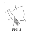
アイウエア物品10を使用するために、開口12をマスク1の呼気弁4の上に配置し、アイウエア物品の下縁を、内側湾曲部13がフィルタカートリッジ5の上方に位置するようにしてマスクの上縁に沿って配置する。アイウエア物品の側縁14を、図4に示すようにマスクの上部ヘッドバンド7の後方に渡し、所望であればその後折目15において前方に曲げ図5に示すようにヘッドバンドの正面で折り畳んでもよい。このように、アイウエア物品10を、マスク係合位置決め手段11、12を呼気弁4においてマスクと係合させハーネス係合位置決め手段14をヘッドバンド7と係合させることにより、湾曲形状で適所に保持する。この位置において、アイウエア物品は、着用者の視野を妨げることなく、流動性の低衝撃異物の直接のはね返しに対して着用者の眼を保護する。
In order to use the
着用者がいつでもアイウエア物品10を自身の視線から取り除きたい(たとえば、塗料噴霧者の場合、進行中の作業の品質を検査するために)場合、それをマスク1およびヘッドバンド7から完全に外すことは比較的単純なことである。アイウエア物品を取り除くことができる前に外さなければならないファスナはなく、着用者の顔面におけるマスクの位置を妨げることなく、したがって呼吸保護のいかなる損失もなく、(しばしば片手のみで)操作を実行することができる。アイウエア物品がまだ良好な状態にある場合、それを再び適所に戻してもよく、そうでない場合、破棄して新しい物品と交換してもよい。両方の場合で、アイウエア物品を、着用されているマスクに着用者の顔面におけるマスクの位置を妨げることなく適合させることができる。
If the wearer wants to remove the
図3に示すアイウエア物品10のさらなる利点は、使用時、マスク1の呼気弁4からの呼気の正常な流れを妨げない、ということである。したがって、暖かい湿った呼気がアイウエア物品にわたって循環しそれを曇らせる危険性がほとんどない。
A further advantage of the
所望であれば、アイウエア物品10は、アイウエア物品が着用者の額に接触する場合に快適性を向上させるために、内面において上縁に隣接して配置された発泡体または他の適当な材料のストリップ16を有してもよい。発泡体ストリップの長さを、その接触のあり得る程度によって変化させてもよい。
If desired, the
側縁14を前方にかつヘッドバンド7の正面で曲げる必要のない場合、図3のアイウエア物品の折目15を省略してもよい。その場合、側縁14を、ヘッドバンドの内面に係合させることにより適所に保持する。
If the
図6〜図8に、上部ヘッドバンド7と係合する代替位置決め手段を提供する、アイウエア物品10の側縁14に対するいくつかの可能な変更態様を示す。
FIGS. 6-8 illustrate several possible modifications to the
図6に示す変更態様は、図3の各折目15をアイウエア物品の各側部14に矩形タブ21を形成するスロットに置き換えることを含む。そして、マスク1の各側部のヘッドバンド7を、それぞれのタブ21の後方に押し込み、図示するようにタブとアイウエア物品の側部14との間に保持することができる。
The modification shown in FIG. 6 includes replacing each
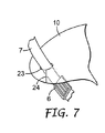
あるいは、図7に示すように、アイウエア物品10の各側部14に開口23を設けてもよく、その中に、マスクの上部ヘッドバンド7を、その開口からアイウエア物品の縁に至るスロット24により案内することができる。スロット24は直線状でなくてもよく、任意の適当な形状の複雑な経路に従い、アイウエア物品がマスクのヘッドバンド7から不注意に分離する危険性を低減するように任意の適当な方向に延在してもよい。
Alternatively, as shown in FIG. 7, an
図8に示すさらに別の変更態様では、2つの平行なスロット25を、アイウエア物品10の側縁に切り込み、矩形タブ26を形成する。タブ26にはさらに、その長さに沿った約中間の地点に横方向の折目27を設ける。この場合、ヘッドバンド7は、アイウエア物品10の一方の面(図8に示すように後面)にあり、タブ26の他方の面の上を横切り、その後タブ26を折目27においてヘッドバンドの周囲で曲げる。
In yet another variation shown in FIG. 8, two
図9および図10は、アイウエア物品10の側部14に対する代替形態を示し、それらの両方において、側部は、上部ヘッドバンド7の代りに下部ヘッドバンド8またはマスクヘッドハーネスの関連するバックル(図1および図2を参照)に係合するように、下方向に拡張されている。図9には、下部ヘッドバンド8または関連するバックルに係合するための鍵穴型の切欠部22Aを有する拡張側部14の下端を示し、図10には、下部ヘッドバンドまたは関連するバックルの周囲に巻き付けることができるようにする折目22Bを有する拡張側部14の下端を示す。
9 and 10 show alternatives to the
図11は、アイウエア物品10のさらに別の変更態様を示し、各側部14を、マスクヘッドハーネスの上部ヘッドバンド7と下部ヘッドバンド8との両方の後方に押し込み、かつそれらにより適所に保持することができるように、下方向に拡張させる。
FIG. 11 shows yet another variation of the
図6〜図11に示す変更態様すべてにより、アイウエア物品10が図3〜図5を参照して上述したものと同様の方法で機能することができる、ということが理解されよう。アイウエア物品の側部14をマスクのヘッドハーネスに係合させるための他の代替位置決め手段が利用可能であり、それには、たとえば、プレススタッドまたは別個のプッシュオンクリップ等の何らかの形態の剥離可能なメカニカルファスナの使用がある。メカニカルファスナを、アイウエア物品の側部14をヘッドバンド7またはヘッドバンド取付点6(ロッキングリング6Aを含む)にもしくはヘッドハーネスの他の任意の適当な部分に係合させるために使用することができる。
It will be appreciated that all of the modifications shown in FIGS. 6-11 allow the
図12は、図3のアイウエア物品10を呼吸マスク1から外すことなくヘッドバンド7から外し着用者の視線から取り除くことができるようにするさらなる変更態様を示す。この変更態様は、開口12の上に、アイウエア物品10の下方延在中央部分11の頂部を横切ってヒンジ線28を形成することを含む。このヒンジ線28により、アイウエア物品を、単に前方に枢動させることにより着用者の視線から取り除くことができる(側縁14はマスクヘッドバンド7から事前に外されている)。アイウエア物品10は、マスクの呼気弁4と係合したままであり、それを、必要な場合は直立位置に戻しマスクヘッドバンド7と再度係合させることができる。当然ながら、アイウエア物品を、交換する必要がある場合、上述したようにマスクから完全に取り除くことも可能である。
FIG. 12 shows a further modification that allows the
図12は、図3に示すタイプのアイウエア物品に設けられたヒンジ線28を示すが、それを図6〜図11を参照して上述した変更されたアイウエア物品に同様に設けてもよい。
12 shows a
図12のアイウエア物品の側縁14を、図13に示すように、マスクヘッドバンド7に係合するための折目30を有する細長いタブ29を含むように変更することにより、アイウエア物品の主部を、使用時にヒンジ線28を中心にわずかに前方に傾斜するようにしてもよい。結果として、アイウエア物品は、着用者の顔面からわずかに遠くに離れて位置することになり、眼鏡の使用が可能になる。
By changing the
同様に図1および図2の呼吸マスク1での使用に適した別のアイウエア物品31を図14に示す。このアイウエア物品は、図3のものと形状が類似しているが、2つの剥離可能なメカニカルファスナ、たとえばプレススタッドによりマスクのヘッドハーネスに取り付けられるように意図されており、メカニカルファスナの各々の一方の部品(33)は、アイウエア物品のそれぞれの側部に取り付けられる。メカニカルファスナの他方の部品(図示せず)は、ヘッドハーネスの適当な取付点、たとえばヘッドバンド7または取付点6(たとえば、バックルロッキングリング6A)に取り付けられる。アイウエア物品の下方延在中央部11もまた、中央部が有効に2つの二叉フォークの形態を有するようにその下端で開口するという点で変更する。この形態では、アイウエア物品31の中央部11を、呼気弁4の上に配置する必要はないが、あるいは、上方から弁の上に摺動させてもよい。図3〜図13のアイウエア物品のいずれに対して同様の変更を行ってもよく、あるいは、アイウエア物品31の中央部11を図3のものと同様に成形してもよい。
Similarly, another
図3〜図14を参照して上述したアイウエア物品の各々は、平坦なシート材料片から形成されるが、マスク1と係合する結果マスク1の適所にある場合、着用者の眼領域を横切って湾曲形態を採用する、ということが理解されよう。所望であれば、シート材料の湾曲した上縁をアイウエア物品の頂部を横切って線34(図3および図14を参照)を中心に前方かつ下方に折り畳むことにより、アイウエア物品を、マスク上に配置する前に強制的に湾曲形態を有するようにしてもよい。その場合、発泡体ストリップ16を省略するかまたは再配置してもよい。望ましい場合に湾曲を容易にするために、シート材料に図3および図14において35で示すもの等の垂直ヒンジ線を形成してもよい。あるいは、平坦なポリマ材料片に、アイウエア物品に所望の程度の湾曲を提供するように曲げることができる材料(たとえば、押出し成形されたアルミニウム)から形成されたフレームを設けてもよく、フレームは、アイウエア物品の実質的に全周縁に沿って延在してもよいが、図12を参照して上述したようにアイウエア物品を前方に折り畳む必要がある場合は、上縁のみに沿って延在すべきである。
Each of the eyewear articles described above with reference to FIGS. 3-14 is formed from a flat piece of sheet material, but when engaged with the
アイウエア物品が呼吸マスクの呼気弁4とより適切に係合するために、アイウエア物品10、31の開口12に発泡体またはゴム製リムを設けてもよい。場合によっては、開口12のリムを、内側に折り返すことが望ましい場合がある(すなわち、それにより、呼気弁に配置された場合に、マスクのフェースピース2に向かって延在することになる)。そして、リムにより、アイウエア物品が呼気弁に過度に押し付けられることがなくなり、リムは、アイウエア物品と着用者の顔面との間に確実に一定の最小間隔が存在するようにする役割を果たす。最小間隔は、たとえば、アイウエア物品の後方で眼鏡を装着することができるために十分な間隔であってもよい。
Foam or rubber rims may be provided in the
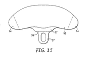
さらなる代替態様として、アイウエア物品10の下方延在部11のみを、呼吸マスクの呼気弁4の上に引き伸ばすことができる材料から形成してもよく、それによりマスクに対しより確実に適合させることができる。同時に、図12に示す方法と同様に、下方延在部11とマスクの残り部分との間の接合によってヒンジを形成し、それを中心にアイウエア物品を前方に折り畳むことができるようにする。また、下方延在部11とアイウエア物品の主部の下部とを、平坦な透明ポリマ材料片38(アイウエア物品のバイザ部を提供する)が取り付けられる別個の成形部品37(図15参照)として形成することも可能である。成形部品37にヒンジ39を形成することにより、図12を参照して説明したように、眼保護具の部分38を前方に折り畳むことができる。アイウエア物品の側部14を、図3〜図14を参照して上述した方法のうちの任意の方法で、呼吸マスクのヘッドハーネスと係合させることができる。
As a further alternative, only the
上述したアイウエア物品10の各々に、呼吸マスクからアイウエア物品10を取り除くのを容易にするために、下方延在部11(図3参照)の下端にタブ11Aを設けてもよい。タブ11Aは、図3に示すようにアイウエア物品の一体部分であってもよいが、それを別個の部材としてより柔軟な材料から形成しその後アイウエア物品に固定してもよい。
Each of the
図3のアイウエア物品10の開口12を、呼吸マスク1の呼気弁4に密接嵌合しているものとして上述した。代替態様として、開口12は、呼気弁より大きくてもよく(それにより、開口の寸法を精密に決める必要がなくなる)、その際、アイウエア物品に、呼気弁構造の適所に保持するための何らかの機構を設ける。たとえば、下方延在部11に弾性コードを、開口12の中央を横切って一方の側部から他方の側部に水平に延在するように固定してもよく、使用時、その弾性コードを、呼気弁4の底部の周囲で引き伸ばしてもよい。あるいは、アイウエア物品10の下方延在部11を、開口12が呼気弁4の上を滑ることができるように開き、その後、開口12の上端および下端が呼気弁構造の上端および下端と確実に係合するようにその元の形態に戻る、水平延在曲面を有するように形成してもよい。
The
上述したアイウエア物品10、31のいずれかを呼気弁の代替形態を有する呼吸マスクと共に使用するのを可能にするために、別個のアダプタを呼気弁に取り付けることにより、弁構造に適当な形状を提供してもよい。アダプタは、たとえば、呼気弁への押込嵌合であってもよい。アダプタの一形態を、図16および図17に示し、別の形態を図18に示す。
To allow any of the
図16および図17に示すアダプタ40は、図14に示すタイプの叉状拡張部11を有するアイウエア物品31と使用することが意図されている。アダプタ40は、アダプタが呼吸マスクの呼気弁に押込嵌合されるのを可能にする中央開口41を有するポリマ材料のブロックを含む。アダプタの側部に溝の対42、43が形成されており、アイウエア物品31の叉状拡張部11が摺動してその中に入ることにより、アイウエア物品が呼吸マスクの着用者の顔面に対し事前に選択された角度で配置される。アダプタ40には、アイウエア物品に対し後方傾斜部を提供する第1溝対42と、垂直位置を提供する第2溝対43と、があるが、溝の数および位置は変更してもよい。代替構造では、アダプタのヒンジ式上部拡張部に溝42、43を形成し、図15を参照して説明したように眼保護具を前方に折り畳むことができるようにする。図16および図17に示すタイプのアダプタを、図3に示すタイプの開口付き拡張部11を有するアイウエア物品10と使用することも可能であるが、その場合、アダプタブロックを、アイウエア物品の開口12のものと対応する外部形状を有するように形成する、ということが理解されよう。
The
図18に示すアダプタ45では、アダプタ40の傾斜溝42を、傾斜案内面46およびアダプタブロックの側部に形成された関連する止め具47と置き換える。このアダプタもまた、図14に示すタイプの叉状拡張部11を有するアイウエア物品31と使用するように意図されているが、アイウエア物品に対し呼吸マスクの着用者の顔面に対する代替位置を提供する。図18は、呼吸マスク1の呼気弁4に配置されたアダプタ45を示し、アイウエア物品31の叉状拡張部11は、それが着用者の顔面(破線48で示す)に非常に近接する位置まで摺動している。しかしながら、代替案内面46および/または代替止め具47を選択することにより、アイウエア物品31を、たとえば眼鏡の着用を可能にするために、着用者の顔面48からさらに離して配置することができる。
In the
図16および図17に示すタイプまたは図18に示すタイプのアダプタと使用する場合、アイウエア物品の側部は、任意の適当な方法で呼吸マスクのヘッドハーネスと離脱可能に係合する。 When used with an adapter of the type shown in FIGS. 16 and 17 or the type shown in FIG. 18, the side of the eyewear article releasably engages the respirator head harness in any suitable manner.
図18のアダプタを、枢支点を提供するように変更してもよく、それは呼気弁構造の各側に1つあり、そこに、アイウエア物品31の叉状拡張部11の下端を離脱可能に取り付けることができる。そのタイプの配置により、側部14が呼吸マスクのヘッドハーネスから外れた後、それが呼吸マスクの正面で下方に垂れ下がるまで、アイウエア物品が前方に枢動することが可能になる。アダプタの両側に止め具を設けることにより、アイウエア物品の端部位置を画定し、必要に応じてそれが確実にそれらの位置の一方または他方で保持されるようにしてもよい。
The adapter of FIG. 18 may be modified to provide a pivot point, one on each side of the exhalation valve structure, in which the lower end of the forked
図19は、フィルタカートリッジ5が差込み嵌合によってマスクに離脱可能に取り付けられていることを除いて図1および図2に示すマスク1と類似している呼吸マスク49を示す。差込み嵌合は、図19には図示されていないが、図20では5Aによって示されている。図20は、フィルタカートリッジ5が一時的に取り除かれ代替形態のアイウエア物品50と適合しているマスク49を示す。アイウエア物品50は、後述するように差込み嵌合部5Aにおいてマスクと係合する支持体51の形態のマスク係合位置決め手段を有する。アイウエア物品50のバイザ部52を、平坦な透明ポリマ材料片によって提供し、その上縁を(図21を参照して後により詳細に説明するように)51Aにおいて支持体51の上端に枢支連結する。支持体51の下端は、フィルタカートリッジ5を取り付ける前に呼吸マスク49の差込み嵌合部5Aの上に押し出すことができる開口付きディスク53を支持し、後にフィルタカートリッジ5により適所に保持される。呼吸マスクが使用されている時、図4のアイウエア物品10に対して上述したように、アイウエア物品の部分52を支持体51の正面に配置し、支持体51により着用者の眼の正面に懸装する。この時、部分52は、側部14(ハーネス係合位置決め手段として機能する)がマスクの上部ヘッドバンド(図示せず)の後方に配置されると、着用者の顔面を横切って湾曲形状を呈する。必要な場合、側部14をヘッドバンドから外し、部分52を上方に接続51Aを中心に着用者の頭部の頂部上に枢動させることにより、アイウエア物品の部分52を着用者の視線から取り除くことができる。
FIG. 19 shows a
図21は、図20のバイザ部52と支持体51のうちの1つとの間の接続51Aの部品を拡大尺でより詳細に示す。この接続により、有利には、バイザ部52の呼吸マスク49に対する垂直位置を調整することも可能である。支持体51の上端は、ホイール82が回転可能に取り付けられるスリーブ81によって包囲され係合されるラック80を支持する。拡大ヘッドを有するポスト83は、ホイール82から放射状に延在し、使用時、バイザ部52の上縁に隣接するスロット84(図20参照)と係合する。ホイール82により、バイザ52が上方に枢動することができ、それによりバイザ部52が着用者の視線から取り除かれ、ラック機構80、81により支持体51上のホイールの垂直位置を調整することができる。
FIG. 21 shows in greater detail the parts of the
図20のアイウエア物品50が呼気弁構造ではなく呼吸用保護具のフィルタ嵌合部と係合するということが理解されよう。アイウエア物品において支持体51を使用してアイウエア物品をフィルタ嵌合部から支持することができるようにすることは本質的ではないが、上述したような支持体により、バイザ部52の呼吸マスクに対する垂直位置を調整することができる。呼吸マスクの形態に応じて、アイウエア物品に、あるいは、支持体51の代りにマスクのフィルタ嵌合部と係合することができる2つの下方延在叉状部(図14のアイウエア物品の部分11に類似する)を設けてもよい。
It will be appreciated that the eyewear article 50 of FIG. 20 engages the filter fitting of the respirator rather than the exhalation valve structure. Although it is not essential to be able to support the eyewear article from the filter fitting using the
図22は、図1および図2または図19に示すタイプの呼吸マスク1およびノーズブリッジ部3を有する他の呼吸ハーフマスクと使用するために適した代替アイウエア物品55を示す。この場合、アイウエア物品は、着用者の視線から一時的に取り除かれる時に呼吸用保護具のヘッドバンド7と係合し続けるように意図される。
FIG. 22 shows an
アイウエア物品55は、平坦シート状の任意の適当な透明ポリマ材料、たとえばポリカーボネートまたはポリエステルを含む。アイウエア物品は、着用者の眼領域の一方の側部から他方の側部まで呼吸マスクの頂部にわたって延在するために必要な大きさにされており、マスクの中央部3のノーズブリッジ領域に位置するノーズピース56を有する。使用時、呼吸用保護具の上部ヘッドバンド7を、アイウエア物品の側縁のスロット57に通す。これにより、ノーズピース56およびスロット57は、夫々、アイウエア物品をマスク着用者の眼の正面に配置するためのマスク係合位置決め手段およびハーネス係合位置決め手段として機能する。
着用者がいつでもアイウエア物品55を自身の視線から取り除きたい場合、それをヘッドバンド7の上方に摺動させて着用者の頭部の頂部に載置することができ、そこで、さらに必要となるまで保持することができ、必要となると、その元の位置に戻すことができる。マスクによって提供される呼吸保護は、このアイウエア物品55の位置の変化によって影響されない。
If the wearer wants to remove the
ノーズピース56を省略してもよく、その場合、アイウエア物品50の下縁58は、図23に示すように中央において内側に湾曲しており、それにより、呼吸マスク1のノーズブリッジ上に位置することになる。ノーズピース56が存在する場合、それをアイウエア物品の残り部分と同じ材料から形成する必要はなく、たとえば、呼吸マスクのノーズブロッジとのより確実な係合を形成する材料から形成してもよい。
The
場合によっては、さらに、アイウエア物品55を、傷がつくかまたは破損した場合に破棄することができるように、マスク1から完全に取り除くことができることが望ましい場合がある。それを達成することができる1つの方法は、アイウエア物品をヘッドバンド7から外すことができるようにスロット57からアイウエア物品55の縁まで延在するスリット(図示せず)を提供することによる。あるいは、アイウエア物品55に、ヘッドバンド7と接続する際に使用するために、図24または図25に示すタイプのスライディングコネクタを設けてもよい。
In some cases, it may further be desirable that the
図24に示すスライドコネクタ60は、略矩形形状のクリップであり、使用時、取付点6とクレードル9(図2を参照)との間でヘッドバンドに沿って後方および前方に移動することができるように、呼吸マスクの上部ヘッドバンド7のうちの1つの周囲に取り付けられる。そうするために、クリップは、ヘッドバンド7が配置される開放通路61を有し、図23に示すように通路へのアクセスを提供するように開放することができる、クリップの残り部分にヒンジ式に取り付けられたカバー62を有する。ヘッドバンドを通路に配置すると、カバー62をクリップファスナ63によって閉鎖し保持する。クリップ60の後面は、アイウエア物品55の隣接する側縁においてスロット57に挿入することができ、それによりアイウエア物品55をヘッドバンドに取り付けることができる、スタッド64を支持する。スタッド64の頭部の両側を平らにすることにより、スタッド64をスロット内に挿入することができるようにし、その後クリップを回転させてヘッドバンド7の標準位置と整列させる。アイウエア物品55の他方の側部を呼吸マスクの他方の側部の上部ヘッドバンド7に取り付けるために、第2のクリップを使用する。この時、アイウエア物品55をヘッドバンド7上で上下に摺動させ、必要に応じてコネクタ60に対して枢動させることによりそれが着用者の頭部の頂部上に押し出されることができるようしてもよいが、クリップ60のスタッド64をアイウエア物品から外すことにより、またはクリップ60を開きそれらをヘッドバンドから取り除くことにより、完全に取り除いてもよい。
The
図25に示すスライドコネクタ65は、クリップ60に対し同様に機能するが、スロットスリーブの形態である。この場合、ヘッドバンドの通路61へのアクセスは、スリーブの一方の面における開口スロット66を介する。スリーブの反対側の面(図24には図示せず)は、スリーブをアイウエア物品に取り付けるために使用されるスタッド64を支持する。
The
クリップ60とスリーブ65とは、ともに、ヘッドバンドに対する張力を増大させることなくかつ呼吸マスクの快適性に影響を与えることなく、着用者の頭部の頂部に対しヘッドバンド7上を上方に摺動させることができるようにする。上昇位置にある時のアイウエア物品の望ましくない移動の危険性を低減するために、通路61の各々は、クリップ60またはスリーブ65をヘッドバンド7の任意の選択された位置で保持しながら同時にまだヘッドバンド7が後方および前方に摺動するのを可能にするように機能する、波状部(図24において67で示す)を有してもよい。
Both the
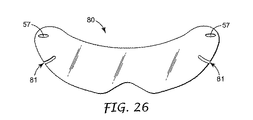
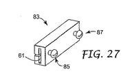
図26は、図23のアイウエア物品に類似するアイウエア物品80を示すが、各側縁において夫々の開口57の下方にスロット81が設けられている。スロット81により、図27に示す変更されたスライディングコネクタ83を使用して、アイウエア物品80を呼吸マスクの上部ヘッドバンド7に接続することができる。コネクタ83は、上述した図25に示すものと同様であるが、その後面に、図24におけるような単一スタッドではなく2つのスタッド85、87が設けられている。2つのかかるコネクタを、アイウエア物品80の各側部に1つ使用し、各場合において、コネクタスタッド85のうちの1つをアイウエア物品のスロット57に配置し、呼吸用保護具ヘッドバンド7を、図25を参照して上述したようにコネクタ通路61に配置する。そして、コネクタ83は、上述したように、アイウエア物品が着用者の頭部の頂部へヘッドバンド7上を上方に摺動することができるように機能する。アイウエア物品を使用する(すなわち、それが呼吸マスクのノーズブリッジに載置される下降位置にある)場合、各コネクタ83の第2のスタッド87を、アイウエア物品の夫々のスロット81に配置し、それは、アイウエア物品のコネクタ83に対する枢動を制限し、それにより、この位置にある時のアイウエア物品に対するさらなる安定性が提供される。
FIG. 26 shows an
ヘッドバンド7においてスライドコネクタ60、65を使用することに対する代替態様として、図22および図23のアイウエア物品55を、クリップを介してヘッドハーネスのクレードル9に枢支結合してもよい。図28は、たとえば、クレードル9の一方の側部とそのヘッドバンド7への取付部とを示し、また、クレードルからヘッドバンドの上部の上に重なるように吊り下げられた細長いクリップ70(図29も参照)も示す。ヘッドバンドの上に重なるクリップ70の部分にラック71が形成されており、これは、アイウエア物品55の夫々のスロット57に挿入することができるスタッド73を有するスライド72を支持する。この構成により、アイウエア物品55が、スタッド73上でクレードル9に対して枢動することができ、スライド72をラック71上で上下に押すことによりクレードルに対して垂直に移動することができる。アイウエア物品55を呼吸マスクから完全に取り除くことが必要である場合、それを、アイウエア物品をスタッド73から外すことによるかまたはクリップ70をクレードル9から外すことにより達成することができる。
As an alternative to using the
図30は、図3のアイウエア物品10の特徴を図22のアイウエア物品55の特徴と結合するアイウエア物品90のさらなる形態を示す。特に、アイウエア物品90は、呼吸マスク1の呼気弁4上に適合する開口12を有する下方延在中央部11とともに、アイウエア物品がマスクヘッドハーネス7に対して上下に摺動するのを可能にする、側縁におけるスロット57(恐らくは、図19および図20を参照して上述したようなスライディングコネクタ60、65または図21または図22を参照して説明したようなクリップと組み合わせて)を有する。
30 illustrates a further form of
図31は、図30のものと同様に、恐らくは図24および図25に示すようなスライディングコネクタかまたは図28および図29に示すようなクリップとともに、アイウエア物品が呼吸マスクのヘッドハーネスに対して上下に摺動するのを可能にする、側縁の開口57を有するアイウエア物品91を示す。アイウエア物品91は、下縁がマスクの呼気弁4の周囲に係合するような形状ではないが代りに呼気弁(図1および図2参照)の両側においてフィルタカートリッジ5の周囲に係合するような形状であるという点で、図30のものと異なる。そのために、アイウエア物品91の下縁は、アイウエア物品91が下降位置にある時に、フィルタカートリッジ5の上に適合し部分的にその下部で湾曲するが、アイウエア物品がフィルタカートリッジから外れ呼吸用保護具ヘッドバンド7上を上方に摺動することによりそれを着用者の視線から取り除くことができるようにする、マスク係合位置決め手段を形成する2つの切欠部92を有する。当然ながら、切欠部92の形状を、アイウエア物品と使用するマスクにおけるフィルタカートリッジの形状に対応するように必要に応じて変更することができる。
FIG. 31 is similar to that of FIG. 30, perhaps with a sliding connector as shown in FIGS. 24 and 25 or a clip as shown in FIGS. 28 and 29, with the eyewear article against the respirator head harness. An
図32は、着用者の視線から取り除かれる場合にマスクヘッドバンド7に係合したままである、図1および図2の呼吸マスク1と使用するために適した、さらに別のアイウエア物品93を示す。アイウエア物品は、各側縁から延在し使用時に図33に示すようにマスクの上部ヘッドバンド7上で夫々のガイド97に通される細長いタブ95の形態のハーネス係合位置決め手段を有する。タブ95の端部を、99で示すように裏返すことにより、後述するようにアイウエア物品93の移動中にタブがガイド97から離れないようにするのを助けるようにしてもよい。同様に図33に示すように、アイウエア物品の下縁の形状を、着用者の眼の正面に配置した場合に、呼気弁構造4の頂部に位置し2つのフィルタカートリッジ5の頂部の周囲に適切に適合するような形状にする。アイウエア物品93を着用者の視線から取り除くためには、それを単に着用者の頭部の頂部に向かって上方に押す。この移動中、細長いタブ95は、ガイド97を通して上方に摺動する。その後、アイウエア物品93を、図33に示す下降位置まで再び引きおろすことができ、それにより細長いタブ95がガイド97を通して再び下方に摺動する。アイウエア物品の移動に対応するために必要な場合、ガイド97は、マスクヘッドバンド7に沿って後方および前方に摺動することができる。アイウエア物品93の下縁から前方に突出する中央タブ101は、アイウエア物品を操作するのを容易にし、下降位置において、図33に示すように呼気弁構造の頂部に位置する。代替態様として、図34に示すように、中央タブ101を、マスク1のフィルタカートリッジ5の頂部の周囲に適合する領域に隣接して、アイウエア物品の下縁における2つのタブまたはフィンガ穴/グリップ101Aと置き換えるかまたはそれらによって補ってもよい。
FIG. 32 shows yet another
アイウエア物品92は、着用者の顔面に隣接する側部においてその周縁の全体の周囲に延在する発泡体ストリップ100を支持する。アイウエア物品が下降位置にある場合、発泡体ストリップ100は、本来アイウエア物品の周縁において顔面とアイウエア物品との間の間隙を通して着用者の顔面に達する可能性のあるはね返しに対する保護を提供する。必要な場合は、ストリップ100を、着用者の顔面に対するシールを形成するように構成してもよい。
The
図35および図36は、図33に示すマスクの上部ヘッドバンド7のガイド97の好ましい形態をより詳細に示す。図35および図36のガイド97を、互いに閉鎖した場合(図35に示すように)、それらの間に、ガイドを通して一方の側部から他方の側部まで延在する溝103を画定する2つの部分102A、102Bで形成し、使用時、アイウエア物品のタブ95の1つをその溝に通す。ガイド97の部分102Aの外側は、図示するように、マスクヘッドバンド7を通すバックルを形成する。
35 and 36 show in more detail the preferred form of the
ガイド97の部分102A、102Bを、ヒンジにより一方の側部に沿って互いに接合し、閉鎖位置(図35)において、クリップ105により他方の側部において合わせて保持する。部分102A、102Bは、代替態様として、両側部に沿ってクリップにより合わせて保持される別個の部品であってもよい。
アイウエア物品のタブ95のための溝103を、部分102A、102Bの対向する内面106A、106Bによりガイド97内に画定する(図36参照)。部分102BにおけるU型スロット108により溝103の面106Bに矩形トング107を形成し、トング107の自由端の内面に、半球状ボタン107’を設ける。ボタン107’を、アイウエア物品93が上昇位置にあるかまたは下降位置にあるかにより、アイウエア物品タブ95の2つの穴109の一方に係合するように配置し、それにより、ボタン107’は、その位置でアイウエア物品を保持するように作用する。ボタン107’が配置されるトング107の可撓性により、アイウエア物品タブ95が溝103を通して移動している時に、ボタンが穴109から外れるように移動することができる。
A
本発明によるアイウエア物品は、図2および図19に示すように中央に配置された呼気弁の両側に2つのフィルタカートリッジが配置された呼吸ハーフマスクとの使用に限定されない。その形状ならびに呼吸マスクおよびヘッドハーネスとの係合の方法を適当に変更することにより、本発明によるアイウエア物品を、成形マスクおよび平坦折畳み型マスクを含む他の形態のハーフマスクおよび1/4マスク(すなわち、着用者の鼻および口を覆うが顎は覆わないマスク)と使用することができる。本発明によるアイウエア物品はまた、図2および図19に示すものと異なる構造のヘッドハーネスを有する呼吸マスクと共に使用することも可能である。 The eyewear article according to the present invention is not limited to use with a breathing half mask in which two filter cartridges are located on either side of a centrally located exhalation valve as shown in FIGS. By appropriately changing the shape and manner of engagement with the respiratory mask and head harness, the eyewear article according to the present invention can be used to form other types of half masks and quarter masks, including molded masks and flat folding masks. (Ie, a mask that covers the wearer's nose and mouth but not the chin). The eyewear article according to the present invention can also be used with a respiratory mask having a head harness with a structure different from that shown in FIGS.
好ましくは、アイウエア物品は、呼吸マスクを決して変更する必要があってはならないが、図16および図18を参照して説明したように、場合によっては、マスクの弁構造の外部形状を変更するために何らかの形態のアダプタが必要である場合もある。 Preferably, the eyewear article should never change the breathing mask, but in some cases changes the external shape of the valve structure of the mask, as described with reference to FIGS. In some cases, some form of adapter is required.
図37および図38は、例として、異なる形態のヘッドハーネスを採用する呼吸マスク110を用いる本発明によるアイウエア物品の使用を示す。図37に示すマスク110は、着用者のノーズブリッジ上に延在するように意図され呼気弁(図示せず)を有する中央部3の両側に配置された2つのフィルタカートリッジ(省略)のための嵌合部5Aを有するという点で、図2および図19のマスク1、49に類似する。しかしながら、マスク110では、上部ヘッドバンド7および下部ヘッドバンド8とマスク1、49の夫々の取付具6とを、2つのより長いヘッドバンド111(マスクの各側に1つ)と置き換える。これらのより長いヘッドバンド111は、ヘッドハーネスのヘッドクレードル(図示せず)からマスクの夫々の案内面113の上端112まで延在し、そこで、フィルタ嵌合部5Aの正面の周囲で支持されることにより案内面の下端114で離れて着用者の頭部の後部に戻る。
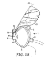
FIGS. 37 and 38 show, by way of example, the use of an eyewear article according to the present invention using a
図38に、呼吸マスク110との使用に適したアイウエア物品115を示す。それは、先に説明したアイウエア物品と同様に、水平方向と垂直方向との両方において着用者の眼領域を覆うようにマスク110の上部から延在するように意図された平坦なポリマ材料の成形片を備える。アイウエア物品の下縁の中央部116を、図23のアイウエア物品55の中央部と同様にアイウエア物品に対しマスク係合位置決め手段を形成するマスク110の中央のノーズブリッジ部3に位置するような形状にする。中央部116の各側部には、上端112から夫々のヘッドバンド案内面113内に挿入しそれによりマスク110のヘッドハーネスに係合することが可能な下方に延在する細長いタブ117がある。アイウエア物品115は、マスクの適所にある時、着用者の眼領域を横切って湾曲形態を呈し、その周縁の全体または一部の周囲に発泡体または他の適当な材料のストリップを設けることにより、着用者の顔面に対するシールを形成しかつ/または周縁のはね返り保護を提供することができる。タブ117をヘッドバンドガイド113から引き出すことにより、マスク110によって提供される呼吸保護に影響を与えることなく、アイウエア物品115をいつでも着用者の視線から取り除くことができる。
FIG. 38 shows an
図39〜図41は、例として、平坦折畳み型マスクにおける本発明によるアイウエア物品の使用を示す。図39において折り畳まれているように示し図40において開いているように示すマスク120は、中央パネル121と、夫々の溶接継目122A、123Aにより中央パネルに接合される上部パネル122および下部パネル123と、を備える。上部ヘッドバンド124および下部ヘッドバンド125を、中央パネル121の両側において外側に延在するタブ部121’に固定する。マスクが折り畳まれている時(図39)、上部パネル122および下部パネル123は、中央パネル122の後方に折り曲がるが、着用者の鼻、口および頬を覆うカップ型フェースピース(図40)を形成するために開く。パネル121、122および123を、着用者が吸入する時に空気が引き込まれる任意の適当な空気透過性フィルタ材料から形成する。放出される空気もまた、フィルタ材料を通してマスクから出てもよく、または中央パネル121に設けられた任意の呼気弁(図示せず)を通して出てもよい。
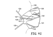
39-41 show, by way of example, the use of an eyewear article according to the present invention in a flat foldable mask. The
図41は、本発明によるアイウエア物品126が設けられる、着用者の顔面129において開いた状態にあるマスク120の側面図を示す。アイウエア物品126は、平坦な、比較的薄くかつ可撓性のポリマ材料の成形片を含み、その下縁の中央部を、中央パネル121の上縁の後方において溶接継目122Aにより形成された窪みに位置するような形状にする。アイウエア物品126は、その側部127が上部ヘッドバンド124を越えて延在するような左右の寸法を有し、それにより、側部は任意の適当な方法で上部ヘッドバンド124と係合することができる。図41は、上部ヘッドバンド124が後方に押し込まれた矩形タブ128を有するように形成されたアイウエア物品126の側部127を示すが、図5〜図8を参照して上述した構成のいずれを有してもよいということが理解されよう。マスク120によって提供される呼吸保護に影響を与えることなく、アイウエア物品126を、着用者の視線から取り除くためにマスク120からいつでも完全に取り外すことができる。
41 shows a side view of the
所望であれば、アイウエア物品126に、アイウエア物品の下縁をマスク120の各側部にあるタブ121’に固定するために使用することができる、任意の適当な構造からなるクリップ(図示せず)を設けてもよい。
If desired, a clip of any suitable structure that can be used to attach the
使用する呼吸マスクの形態に応じて、本発明によるアイウエア物品のその下縁に沿って、マスクの外面に接して位置しそれに対して密閉する適当なより柔軟な材料のスカートを設けてもよい。 Depending on the form of respirator used, a skirt of a suitable more flexible material may be provided along its lower edge of the eyewear article according to the present invention that is located against and seals against the outer surface of the mask. .
図面を参照して上述したアイウエア物品は、比較的容易に製造することができ、材料を適当に選択することにより、傷が付くかまたは破損した場合に完全に処分することができる。アイウエア物品のバイザ部に使用する材料を、使用することが意図される環境を考慮して選択する。たとえば、環境によっては、色付きの透明材料または何らかの波長の光をフィルタリングするように設計された材料が望ましい場合がある(たとえば、バイザを溶接する際に使用するために既知である光遮蔽材料を含む)。必要な場合は、アイウエア物品の任意のものに、バイザ部の外縁の全体または一部に隣接して発泡体または他の適当な材料のストリップを設けることにより、着用者の顔面に対するシールを形成しかつ/または必要な場合に周縁のはね返り保護を提供してもよい。いずれの場合も、アイウエア物品を使用することにより、マスクによって提供される呼吸保護が脅かされることも損なわれることもない。アイウエア物品に、平坦な透明ポリマーシート材料の周縁の一部または全体に沿って延在するフレームを設ける場合、シート材料を、フレームから取外し可能でありフレームにおいて交換可能であってもよく、それにより、シート材料が破棄される場合であってもフレームを保持することができる。 The eyewear article described above with reference to the drawings can be manufactured relatively easily and can be completely disposed of if it is scratched or broken by appropriate selection of materials. The material used for the visor portion of the eyewear article is selected in view of the environment in which it is intended to be used. For example, in some environments, colored transparent materials or materials designed to filter light of some wavelength may be desirable (eg, including light shielding materials known for use in welding visors). ). If necessary, any eyewear article may be provided with a seal against the wearer's face by providing a strip of foam or other suitable material adjacent to all or part of the outer edge of the visor section. And / or peripheral bounce protection if necessary. In either case, the use of eyewear articles does not threaten or compromise the respiratory protection provided by the mask. When the eyewear article is provided with a frame that extends along part or all of the periphery of the flat transparent polymer sheet material, the sheet material may be removable from the frame and replaceable in the frame, Thus, the frame can be held even when the sheet material is discarded.
本発明は、その精神および範囲から逸脱することなくさまざまな変更態様および代替態様をとってもよい。したがって、本発明は上述したものに限定されるべきではなく、特許請求の範囲およびその任意の等価物において示される限定によって規制されるべきである、ということを理解されたい。また、本発明を、本明細書で特に開示していない任意の要素がなくても適当に実施することができる、ということも理解されたい。 The present invention may take various modifications and alternatives without departing from the spirit and scope thereof. Therefore, it should be understood that the invention is not to be limited to what has been described above, but is to be limited by the limitations as set forth in the appended claims and any equivalents thereof. It should also be understood that the present invention may be suitably practiced without any elements not specifically disclosed herein.
Claims (10)
バイザ部を提供する平坦な透明ポリマ材料片と、
マスク係合位置決め手段と、
ハーネス係合位置決め手段と、
を具備し、
該マスク係合位置決め手段と該ハーネス係合位置決め手段とが、夫々、該マスクと該ヘッドハーネスとに係合可能であることにより、該平坦な透明ポリマ材料片が湾曲形状を呈するようになり、該マスクが着用されている時、該バイザ部が該着用者の眼の正面に配置されて該ポリマ材料片が該着用者の顔面の一方の側部から他方の側部まで延在し、
該マスクが着用されている間に該マスクおよび/または該ヘッドハーネスから外すことができるようにしたことにより、該着用者の顔面における該マスクの位置を妨げることなくかつ該マスクによって提供される呼吸保護に影響を与えることなく該着用者の視線から取り除くことができる、アイウエア物品。 An eyewear article for use with a respiratory mask provided with a head harness,
A flat transparent polymer material piece providing a visor part; and
Mask engagement positioning means;
Harness engagement positioning means;
Comprising
The mask engagement positioning means and the harness engagement positioning means are respectively engageable with the mask and the head harness, so that the flat transparent polymer material piece has a curved shape, When the mask is worn, the visor portion is placed in front of the wearer's eye and the piece of polymer material extends from one side of the wearer's face to the other side;
Breathing provided by the mask without interfering with the position of the mask on the wearer's face by allowing it to be removed from the mask and / or the head harness while the mask is being worn An eyewear article that can be removed from the wearer's line of sight without affecting protection.
The eyewear article of claim 1, comprising a strip of sealing material extending at least partially around the periphery of the eyewear article at a side adjacent to the face of the wearer.
Applications Claiming Priority (2)
| Application Number | Priority Date | Filing Date | Title |
|---|---|---|---|
| GBGB0216284.0A GB0216284D0 (en) | 2002-07-15 | 2002-07-15 | Eye-wear articles for use with respiratory masks |
| PCT/US2003/020720 WO2004006815A2 (en) | 2002-07-15 | 2003-07-01 | Eye-wear articles for use with respiratory masks |
Publications (2)
| Publication Number | Publication Date |
|---|---|
| JP2005532865A true JP2005532865A (en) | 2005-11-04 |
| JP2005532865A5 JP2005532865A5 (en) | 2006-08-10 |
Family
ID=9940378
Family Applications (1)
| Application Number | Title | Priority Date | Filing Date |
|---|---|---|---|
| JP2004521515A Pending JP2005532865A (en) | 2002-07-15 | 2003-07-01 | Eyewear articles for use with respiratory masks |
Country Status (7)
| Country | Link |
|---|---|
| US (1) | US7077128B2 (en) |
| EP (1) | EP1521561A2 (en) |
| JP (1) | JP2005532865A (en) |
| AU (1) | AU2003280961A1 (en) |
| CA (1) | CA2492756A1 (en) |
| GB (1) | GB0216284D0 (en) |
| WO (1) | WO2004006815A2 (en) |
Cited By (4)
| Publication number | Priority date | Publication date | Assignee | Title |
|---|---|---|---|---|
| WO2019009589A1 (en) * | 2017-07-03 | 2019-01-10 | 왕종문 | Goggles including mask |
| KR101969520B1 (en) * | 2017-10-25 | 2019-04-16 | 강한옥 | Goggle mask |
| JP2019061265A (en) * | 2014-05-07 | 2019-04-18 | デクセリアルズ株式会社 | Spectacles protector |
| JP2021195636A (en) * | 2020-06-10 | 2021-12-27 | owlking株式会社 | Mask cover |
Families Citing this family (34)
| Publication number | Priority date | Publication date | Assignee | Title |
|---|---|---|---|---|
| US8261375B1 (en) | 2003-06-19 | 2012-09-11 | Reaux Brian K | Method of forming a protective covering for the face and eyes |
| US20050081849A1 (en) * | 2003-09-18 | 2005-04-21 | Sydney Warren | Personal oxygen and air delivery system |
| WO2006047817A1 (en) * | 2004-11-03 | 2006-05-11 | Anastasios Stampoultzis | Oxygen- aerosol mask |
| CA2549789A1 (en) * | 2005-06-03 | 2006-12-03 | Primed Medical Products Inc. | Medical face mask |
| US20070050892A1 (en) * | 2005-08-19 | 2007-03-08 | Steven Charles | Welder's helmet with respirator |
| US7488068B2 (en) * | 2006-04-28 | 2009-02-10 | Kimberly-Clark Worldwide, Inc. | Eyewear with mask attachment features |
| US7648234B2 (en) * | 2006-04-28 | 2010-01-19 | Kimberly-Clark Worldwide, Inc. | Eyewear with heating elements |
| US20070252943A1 (en) * | 2006-04-28 | 2007-11-01 | Welchel Debra N | Eyewear with enhanced air flow and/or absorption features |
| US20070252944A1 (en) * | 2006-04-28 | 2007-11-01 | Welchel Debra N | Eyewear with enhanced fit |
| NZ573111A (en) * | 2006-04-28 | 2012-02-24 | Cambridge Scient Pty Ltd | Cox-2 inhibitor |
| KR100751678B1 (en) | 2006-09-27 | 2007-08-23 | 박기수 | Mask with goggles |
| US7475982B2 (en) * | 2006-12-15 | 2009-01-13 | Kimberly-Clark Worldwide, Inc. | Vapor barrier attachment for eyewear |
| US20090078268A1 (en) * | 2007-09-20 | 2009-03-26 | 3 M Innovative Properties Company | Buckle having a flexural strap attachment member and respirator using such buckle |
| WO2009038918A1 (en) * | 2007-09-20 | 2009-03-26 | 3M Innovative Properties Company | Filtering face-piece respirator having buckles integral to the mask body support structure |
| AU2008330013B2 (en) * | 2007-11-28 | 2012-01-19 | 3M Innovative Properties Company | Respirator system including removable head suspension |
| US8375951B2 (en) * | 2008-02-06 | 2013-02-19 | 3M Innovative Properties Company | Buckle and respirator using such buckle, having a deformable cinch bar, and method |
| WO2011009188A1 (en) | 2009-07-22 | 2011-01-27 | Primed Medical Products Inc. | Face mask with truncated nosepiece |
| US9610419B2 (en) * | 2011-08-23 | 2017-04-04 | Koninklijke Philips N.V. | Patient interface assembly with self-adjusting anchor points |
| ITBS20110152A1 (en) * | 2011-11-02 | 2013-05-03 | Mario Mella | DEVICE FOR FILTERED BREATHING |
| US9375105B2 (en) * | 2012-05-04 | 2016-06-28 | Gk Thomson Development, Llc | Adjustable headband pillow |
| DE102012013413A1 (en) | 2012-07-05 | 2014-01-09 | Li-Tec Battery Gmbh | Hybrid electrochemical energy storage |
| US9125448B2 (en) * | 2013-05-30 | 2015-09-08 | Msa Technology, Llc | Support for visors and face shields |
| WO2015006679A2 (en) * | 2013-07-11 | 2015-01-15 | Aqua Turf International, Inc. | Air filtration mask with opening front cover |
| USD746439S1 (en) * | 2013-12-30 | 2015-12-29 | Kimberly-Clark Worldwide, Inc. | Combination valve and buckle set for disposable respirators |
| DE102017211182A1 (en) | 2017-06-30 | 2019-01-03 | Uvex Arbeitsschutz Gmbh | Respiratory half mask |
| US20210275840A1 (en) * | 2020-03-09 | 2021-09-09 | Omachron Intellectual Property Inc. | Filter mask |
| CA3085021C (en) | 2020-03-09 | 2022-07-26 | Omachron Intellectual Property Inc. | Filter mask |
| US11219254B2 (en) | 2020-03-13 | 2022-01-11 | Pabban Development, Inc. | Personal protection system and method |
| CN111251607A (en) * | 2020-03-14 | 2020-06-09 | 北京工业大学 | Manufacturing method of 3D printing intelligent integrated protective mask |
| US11400323B2 (en) | 2020-06-17 | 2022-08-02 | Sleevz Inc. | Protective face coverings |
| US11109625B1 (en) * | 2021-04-30 | 2021-09-07 | Aver Technologies, Inc. | Face mask and shield combination |
| GB2609753A (en) * | 2021-07-09 | 2023-02-15 | Polarseal Tapes And Conversions Ltd | Improvements to protection apparatus |
| US20230233886A1 (en) * | 2022-01-24 | 2023-07-27 | Forged Air Ltd. | Respirator |
| GB2623077A (en) * | 2022-10-03 | 2024-04-10 | Avon Polymer Prod Ltd | Respirator |
Citations (4)
| Publication number | Priority date | Publication date | Assignee | Title |
|---|---|---|---|---|
| JPH0677716U (en) * | 1993-04-20 | 1994-11-01 | 忠泰 竹原 | Face protection and goggles |
| JP2001070318A (en) * | 1999-09-06 | 2001-03-21 | Motoko Iwabuchi | Facial protective shield for surgical operation |
| JP2001505080A (en) * | 1996-09-24 | 2001-04-17 | ミネソタ マイニング アンド マニュファクチャリング カンパニー | Full face respirator with integral molded connector in lens area |
| JP2001525203A (en) * | 1997-12-05 | 2001-12-11 | ミネソタ マイニング アンド マニュファクチャリング カンパニー | Protective article having a transparent shield |
Family Cites Families (43)
| Publication number | Priority date | Publication date | Assignee | Title |
|---|---|---|---|---|
| US2462005A (en) | 1947-09-27 | 1949-02-15 | American Optical Corp | Face shield for use with respirators |
| US2762368A (en) * | 1954-01-22 | 1956-09-11 | Martindale Electric Company Lt | Respiratory masks |
| US2740400A (en) * | 1954-04-30 | 1956-04-03 | Western Electric Co | Combined respirator and face shield |
| US3971368A (en) * | 1975-08-13 | 1976-07-27 | Puritan Equipment, Inc. | Combined oxygen mask and smoke goggle apparatus with automatic flush valve |
| FR2375873A1 (en) | 1976-12-28 | 1978-07-28 | Intertechnique Sa | RESPIRATORY EQUIPMENT IMPROVEMENTS FOR HIGH ALTITUDE FLIGHTS |
| US4126131A (en) | 1977-03-18 | 1978-11-21 | Sierra Engineering Co. | Facemask and goggle combination for excluding smoke or noxious gases from the goggles |
| US4109320A (en) | 1977-06-10 | 1978-08-29 | Sellstrom Manufacturing Company | Attaching assembly |
| US4419994A (en) | 1980-07-03 | 1983-12-13 | Racal Safety Limited | Respirators |
| US4479738A (en) | 1983-04-27 | 1984-10-30 | Sellstrom Manufacturing Company | Attaching assembly |
| US4600002A (en) | 1984-10-24 | 1986-07-15 | American Optical Corporation | Disposable respirator |
| US4701965A (en) | 1985-10-11 | 1987-10-27 | Landis Timothy J | Visor-type mask for dentists |
| DE3630516A1 (en) | 1986-09-08 | 1988-03-10 | Artur Foehl | Continuously adjustable visor device for crash helmets |
| US4883547A (en) | 1987-03-02 | 1989-11-28 | Minnesota Mining And Manufacturing Company | Method of forming a high efficiency respirator |
| US4920960A (en) | 1987-10-02 | 1990-05-01 | Tecnol, Inc. | Body fluids barrier mask |
| US5150703A (en) | 1987-10-02 | 1992-09-29 | Tecnol Medical Products, Inc. | Liquid shield visor for a surgical mask with a bottom notch to reduce glare |
| US5406943A (en) * | 1987-10-02 | 1995-04-18 | Tcnl Technologies, Inc. | Method of manufacturing a liquid shield |
| US4965887A (en) | 1987-11-12 | 1990-10-30 | John A. Paoluccio | Face protector for splash and spatter protection |
| US4945574A (en) | 1988-02-09 | 1990-08-07 | Dhl Research And Development Corporation | Protective mask |
| US4944294A (en) | 1988-04-20 | 1990-07-31 | Borek Jr Theodore S | Face mask with integral anti-glare, anti-fog eye shield |
| US4964171A (en) | 1988-05-16 | 1990-10-23 | Landis Timothy J | Protective shield and visor |
| US5303423A (en) | 1990-01-12 | 1994-04-19 | Splash Shield, Limited Partnership | Face shield/mask combination |
| JPH077285Y2 (en) | 1991-02-19 | 1995-02-22 | 昭栄化工株式会社 | Helmet shield device |
| US5374458A (en) | 1992-03-13 | 1994-12-20 | Minnesota Mining And Manufacturing Company | Molded, multiple-layer face mask |
| US5406944A (en) * | 1993-07-13 | 1995-04-18 | Splash Shield Limited Partnership | Mask with adjustable shield |
| US5446925A (en) * | 1993-10-27 | 1995-09-05 | Minnesota Mining And Manufacturing Company | Adjustable face shield |
| US5553608A (en) * | 1994-07-20 | 1996-09-10 | Tecnol Medical Products, Inc. | Face mask with enhanced seal and method |
| JP3616653B2 (en) | 1994-01-19 | 2005-02-02 | 興研株式会社 | Protective face for safety cap |
| DE9401066U1 (en) | 1994-01-22 | 1994-03-10 | Fallert Werner | Safety helmet with a face protection device |
| FR2715572B1 (en) * | 1994-02-02 | 1996-04-26 | Intertechnique Sa | Head protection equipment with respiratory mask and optical screen. |
| US5584078A (en) * | 1994-11-16 | 1996-12-17 | Saboory; Majid | Detachable/disposable face shield for surgical mask |
| US5666671A (en) | 1994-12-07 | 1997-09-16 | Daneshvar; Yousef | Facial mask |
| ES2170228T3 (en) | 1995-03-09 | 2002-08-01 | Minnesota Mining & Mfg | PERSONAL DEVICES OF RESPIRATORY PROTECTION FOLDED PLANS AND PROCEDURES TO PREPARE THE SAME. |
| US5689833A (en) | 1995-05-03 | 1997-11-25 | Minnesota Mining And Manufacturing Company | Eye shield for a respiratory mask |
| US5704073A (en) * | 1995-08-01 | 1998-01-06 | Figgie International Inc. | Quick donning goggles for use with breathing mask |
| GB9515987D0 (en) | 1995-08-04 | 1995-10-04 | Racal Health & Safety Ltd | Filter mask with eye sheild |
| JP3891623B2 (en) | 1996-12-17 | 2007-03-14 | 株式会社Shoei | Helmet shield plate mounting mechanism |
| KR100526272B1 (en) | 1997-08-04 | 2005-11-08 | 미네소타 마이닝 앤드 매뉴팩춰링 캄파니 | Filtering face mask, filtering face mask set comprising the same and method of using the smae |
| US6732733B1 (en) | 1997-10-03 | 2004-05-11 | 3M Innovative Properties Company | Half-mask respirator with head harness assembly |
| US6216695B1 (en) * | 1998-05-07 | 2001-04-17 | Softy-Flex Inc. | Disposable surgical face mask with retractable eye shield |
| US6264392B1 (en) | 1999-08-25 | 2001-07-24 | Mine Safety Appliances Company | Pivot joint for faceshield assembly |
| GB2354450B (en) | 1999-09-22 | 2003-08-06 | Joseph Anthony Griffiths | Facemask with adjustable visor |
| US6687910B1 (en) * | 2002-09-13 | 2004-02-10 | Ronald F. Smallwood | Smoke simulating shield covering SCBA faceplate |
| US6758215B2 (en) * | 2002-10-17 | 2004-07-06 | Paul G. Begum | Aromatic travel mask |
-
2002
- 2002-07-15 GB GBGB0216284.0A patent/GB0216284D0/en not_active Ceased
-
2003
- 2003-07-01 AU AU2003280961A patent/AU2003280961A1/en not_active Abandoned
- 2003-07-01 CA CA002492756A patent/CA2492756A1/en not_active Abandoned
- 2003-07-01 WO PCT/US2003/020720 patent/WO2004006815A2/en active Application Filing
- 2003-07-01 JP JP2004521515A patent/JP2005532865A/en active Pending
- 2003-07-01 EP EP03742362A patent/EP1521561A2/en not_active Withdrawn
- 2003-07-01 US US10/611,179 patent/US7077128B2/en not_active Expired - Fee Related
Patent Citations (4)
| Publication number | Priority date | Publication date | Assignee | Title |
|---|---|---|---|---|
| JPH0677716U (en) * | 1993-04-20 | 1994-11-01 | 忠泰 竹原 | Face protection and goggles |
| JP2001505080A (en) * | 1996-09-24 | 2001-04-17 | ミネソタ マイニング アンド マニュファクチャリング カンパニー | Full face respirator with integral molded connector in lens area |
| JP2001525203A (en) * | 1997-12-05 | 2001-12-11 | ミネソタ マイニング アンド マニュファクチャリング カンパニー | Protective article having a transparent shield |
| JP2001070318A (en) * | 1999-09-06 | 2001-03-21 | Motoko Iwabuchi | Facial protective shield for surgical operation |
Cited By (6)
| Publication number | Priority date | Publication date | Assignee | Title |
|---|---|---|---|---|
| JP2019061265A (en) * | 2014-05-07 | 2019-04-18 | デクセリアルズ株式会社 | Spectacles protector |
| WO2019009589A1 (en) * | 2017-07-03 | 2019-01-10 | 왕종문 | Goggles including mask |
| KR20190004069A (en) * | 2017-07-03 | 2019-01-11 | 왕종문 | Goggle having mask |
| KR101964250B1 (en) | 2017-07-03 | 2019-04-01 | 왕종문 | Goggle having mask |
| KR101969520B1 (en) * | 2017-10-25 | 2019-04-16 | 강한옥 | Goggle mask |
| JP2021195636A (en) * | 2020-06-10 | 2021-12-27 | owlking株式会社 | Mask cover |
Also Published As
| Publication number | Publication date |
|---|---|
| US20040069302A1 (en) | 2004-04-15 |
| EP1521561A2 (en) | 2005-04-13 |
| GB0216284D0 (en) | 2002-08-21 |
| WO2004006815A3 (en) | 2004-03-18 |
| CA2492756A1 (en) | 2004-01-22 |
| AU2003280961A8 (en) | 2004-02-02 |
| WO2004006815A2 (en) | 2004-01-22 |
| AU2003280961A1 (en) | 2004-02-02 |
| US7077128B2 (en) | 2006-07-18 |
Similar Documents
| Publication | Publication Date | Title |
|---|---|---|
| JP2005532865A (en) | Eyewear articles for use with respiratory masks | |
| JP3803728B2 (en) | Respirator eye shield | |
| EP2191736B1 (en) | Wearable protective device | |
| US6016805A (en) | Face seal for respirator | |
| US20040226563A1 (en) | Face Mask with Double Breathing Chambers | |
| JP2012179429A (en) | Goggle with removable frame and methods of making and using the same | |
| JPS5832994B2 (en) | smoke mask | |
| US20230338755A1 (en) | Face Mask with Improved Face Seal | |
| JP7385961B2 (en) | face mask for fire evacuation | |
| US5890236A (en) | Firefighter goggles | |
| KR20200081121A (en) | Goggle mask | |
| KR20230023805A (en) | face cover system | |
| US20230337763A1 (en) | Mask | |
| KR102523855B1 (en) | Mask | |
| AU2009245816B2 (en) | Wearable protective device | |
| JP2022007931A (en) | Face mask for operation | |
| CN117771042A (en) | Flexible welding mask | |
| KR20230089694A (en) | Mask for easy exhalation of air | |
| JP2022007931A5 (en) |
Legal Events
| Date | Code | Title | Description |
|---|---|---|---|
| A521 | Written amendment |
Free format text: JAPANESE INTERMEDIATE CODE: A523 Effective date: 20060623 |
|
| A621 | Written request for application examination |
Free format text: JAPANESE INTERMEDIATE CODE: A621 Effective date: 20060623 |
|
| A131 | Notification of reasons for refusal |
Free format text: JAPANESE INTERMEDIATE CODE: A131 Effective date: 20090616 |
|
| A601 | Written request for extension of time |
Free format text: JAPANESE INTERMEDIATE CODE: A601 Effective date: 20090916 |
|
| RD03 | Notification of appointment of power of attorney |
Free format text: JAPANESE INTERMEDIATE CODE: A7423 Effective date: 20090916 |
|
| A602 | Written permission of extension of time |
Free format text: JAPANESE INTERMEDIATE CODE: A602 Effective date: 20090930 |
|
| A601 | Written request for extension of time |
Free format text: JAPANESE INTERMEDIATE CODE: A601 Effective date: 20091016 |
|
| A602 | Written permission of extension of time |
Free format text: JAPANESE INTERMEDIATE CODE: A602 Effective date: 20091023 |
|
| A601 | Written request for extension of time |
Free format text: JAPANESE INTERMEDIATE CODE: A601 Effective date: 20091116 |
|
| A602 | Written permission of extension of time |
Free format text: JAPANESE INTERMEDIATE CODE: A602 Effective date: 20091124 |
|
| RD04 | Notification of resignation of power of attorney |
Free format text: JAPANESE INTERMEDIATE CODE: A7424 Effective date: 20091228 |
|
| A02 | Decision of refusal |
Free format text: JAPANESE INTERMEDIATE CODE: A02 Effective date: 20100302 |