JP2005523843A - System and method for freezing, storing and thawing biopharmaceutical material - Google Patents
System and method for freezing, storing and thawing biopharmaceutical material Download PDFInfo
- Publication number
- JP2005523843A JP2005523843A JP2003539439A JP2003539439A JP2005523843A JP 2005523843 A JP2005523843 A JP 2005523843A JP 2003539439 A JP2003539439 A JP 2003539439A JP 2003539439 A JP2003539439 A JP 2003539439A JP 2005523843 A JP2005523843 A JP 2005523843A
- Authority
- JP
- Japan
- Prior art keywords
- container
- frame
- flexible container
- temperature control
- control unit
- Prior art date
- Legal status (The legal status is an assumption and is not a legal conclusion. Google has not performed a legal analysis and makes no representation as to the accuracy of the status listed.)
- Pending
Links
- 0 C(*=C1CC1)N1**C1 Chemical compound C(*=C1CC1)N1**C1 0.000 description 1
Images


Classifications
-
- F—MECHANICAL ENGINEERING; LIGHTING; HEATING; WEAPONS; BLASTING
- F25—REFRIGERATION OR COOLING; COMBINED HEATING AND REFRIGERATION SYSTEMS; HEAT PUMP SYSTEMS; MANUFACTURE OR STORAGE OF ICE; LIQUEFACTION SOLIDIFICATION OF GASES
- F25D—REFRIGERATORS; COLD ROOMS; ICE-BOXES; COOLING OR FREEZING APPARATUS NOT OTHERWISE PROVIDED FOR
- F25D31/00—Other cooling or freezing apparatus
- F25D31/001—Plate freezers
-
- A—HUMAN NECESSITIES
- A01—AGRICULTURE; FORESTRY; ANIMAL HUSBANDRY; HUNTING; TRAPPING; FISHING
- A01N—PRESERVATION OF BODIES OF HUMANS OR ANIMALS OR PLANTS OR PARTS THEREOF; BIOCIDES, e.g. AS DISINFECTANTS, AS PESTICIDES OR AS HERBICIDES; PEST REPELLANTS OR ATTRACTANTS; PLANT GROWTH REGULATORS
- A01N1/00—Preservation of bodies of humans or animals, or parts thereof
- A01N1/02—Preservation of living parts
- A01N1/0236—Mechanical aspects
- A01N1/0242—Apparatuses, i.e. devices used in the process of preservation of living parts, such as pumps, refrigeration devices or any other devices featuring moving parts and/or temperature controlling components
- A01N1/0252—Temperature controlling refrigerating apparatus, i.e. devices used to actively control the temperature of a designated internal volume, e.g. refrigerators, freeze-drying apparatus or liquid nitrogen baths
- A01N1/0257—Stationary or portable vessels generating cryogenic temperatures
-
- A—HUMAN NECESSITIES
- A01—AGRICULTURE; FORESTRY; ANIMAL HUSBANDRY; HUNTING; TRAPPING; FISHING
- A01N—PRESERVATION OF BODIES OF HUMANS OR ANIMALS OR PLANTS OR PARTS THEREOF; BIOCIDES, e.g. AS DISINFECTANTS, AS PESTICIDES OR AS HERBICIDES; PEST REPELLANTS OR ATTRACTANTS; PLANT GROWTH REGULATORS
- A01N1/00—Preservation of bodies of humans or animals, or parts thereof
- A01N1/02—Preservation of living parts
- A01N1/0236—Mechanical aspects
- A01N1/0263—Non-refrigerated containers specially adapted for transporting or storing living parts whilst preserving, e.g. cool boxes, blood bags or "straws" for cryopreservation
-
- A—HUMAN NECESSITIES
- A23—FOODS OR FOODSTUFFS; TREATMENT THEREOF, NOT COVERED BY OTHER CLASSES
- A23L—FOODS, FOODSTUFFS, OR NON-ALCOHOLIC BEVERAGES, NOT COVERED BY SUBCLASSES A21D OR A23B-A23J; THEIR PREPARATION OR TREATMENT, e.g. COOKING, MODIFICATION OF NUTRITIVE QUALITIES, PHYSICAL TREATMENT; PRESERVATION OF FOODS OR FOODSTUFFS, IN GENERAL
- A23L3/00—Preservation of foods or foodstuffs, in general, e.g. pasteurising, sterilising, specially adapted for foods or foodstuffs
- A23L3/36—Freezing; Subsequent thawing; Cooling
- A23L3/363—Freezing; Subsequent thawing; Cooling the materials not being transported through or in the apparatus with or without shaping, e.g. in form of powder, granules, or flakes
- A23L3/364—Freezing; Subsequent thawing; Cooling the materials not being transported through or in the apparatus with or without shaping, e.g. in form of powder, granules, or flakes with packages or with shaping in form of blocks or portions
-
- A—HUMAN NECESSITIES
- A23—FOODS OR FOODSTUFFS; TREATMENT THEREOF, NOT COVERED BY OTHER CLASSES
- A23L—FOODS, FOODSTUFFS, OR NON-ALCOHOLIC BEVERAGES, NOT COVERED BY SUBCLASSES A21D OR A23B-A23J; THEIR PREPARATION OR TREATMENT, e.g. COOKING, MODIFICATION OF NUTRITIVE QUALITIES, PHYSICAL TREATMENT; PRESERVATION OF FOODS OR FOODSTUFFS, IN GENERAL
- A23L3/00—Preservation of foods or foodstuffs, in general, e.g. pasteurising, sterilising, specially adapted for foods or foodstuffs
- A23L3/36—Freezing; Subsequent thawing; Cooling
- A23L3/365—Thawing subsequent to freezing
-
- A—HUMAN NECESSITIES
- A61—MEDICAL OR VETERINARY SCIENCE; HYGIENE
- A61M—DEVICES FOR INTRODUCING MEDIA INTO, OR ONTO, THE BODY; DEVICES FOR TRANSDUCING BODY MEDIA OR FOR TAKING MEDIA FROM THE BODY; DEVICES FOR PRODUCING OR ENDING SLEEP OR STUPOR
- A61M1/00—Suction or pumping devices for medical purposes; Devices for carrying-off, for treatment of, or for carrying-over, body-liquids; Drainage systems
- A61M1/02—Blood transfusion apparatus
- A61M1/0272—Apparatus for treatment of blood or blood constituents prior to or for conservation, e.g. freezing, drying or centrifuging
- A61M1/0277—Frames constraining or supporting bags, e.g. during freezing
-
- A—HUMAN NECESSITIES
- A61—MEDICAL OR VETERINARY SCIENCE; HYGIENE
- A61M—DEVICES FOR INTRODUCING MEDIA INTO, OR ONTO, THE BODY; DEVICES FOR TRANSDUCING BODY MEDIA OR FOR TAKING MEDIA FROM THE BODY; DEVICES FOR PRODUCING OR ENDING SLEEP OR STUPOR
- A61M1/00—Suction or pumping devices for medical purposes; Devices for carrying-off, for treatment of, or for carrying-over, body-liquids; Drainage systems
- A61M1/02—Blood transfusion apparatus
- A61M1/0281—Apparatus for treatment of blood or blood constituents prior to transfusion, e.g. washing, filtering or thawing
-
- F—MECHANICAL ENGINEERING; LIGHTING; HEATING; WEAPONS; BLASTING
- F25—REFRIGERATION OR COOLING; COMBINED HEATING AND REFRIGERATION SYSTEMS; HEAT PUMP SYSTEMS; MANUFACTURE OR STORAGE OF ICE; LIQUEFACTION SOLIDIFICATION OF GASES
- F25D—REFRIGERATORS; COLD ROOMS; ICE-BOXES; COOLING OR FREEZING APPARATUS NOT OTHERWISE PROVIDED FOR
- F25D25/00—Charging, supporting, and discharging the articles to be cooled
-
- F—MECHANICAL ENGINEERING; LIGHTING; HEATING; WEAPONS; BLASTING
- F25—REFRIGERATION OR COOLING; COMBINED HEATING AND REFRIGERATION SYSTEMS; HEAT PUMP SYSTEMS; MANUFACTURE OR STORAGE OF ICE; LIQUEFACTION SOLIDIFICATION OF GASES
- F25B—REFRIGERATION MACHINES, PLANTS OR SYSTEMS; COMBINED HEATING AND REFRIGERATION SYSTEMS; HEAT PUMP SYSTEMS
- F25B2600/00—Control issues
- F25B2600/07—Remote controls
-
- F—MECHANICAL ENGINEERING; LIGHTING; HEATING; WEAPONS; BLASTING
- F25—REFRIGERATION OR COOLING; COMBINED HEATING AND REFRIGERATION SYSTEMS; HEAT PUMP SYSTEMS; MANUFACTURE OR STORAGE OF ICE; LIQUEFACTION SOLIDIFICATION OF GASES
- F25D—REFRIGERATORS; COLD ROOMS; ICE-BOXES; COOLING OR FREEZING APPARATUS NOT OTHERWISE PROVIDED FOR
- F25D2331/00—Details or arrangements of other cooling or freezing apparatus not provided for in other groups of this subclass
- F25D2331/80—Type of cooled receptacles
- F25D2331/801—Bags
- F25D2331/8014—Bags for medical use
-
- F—MECHANICAL ENGINEERING; LIGHTING; HEATING; WEAPONS; BLASTING
- F25—REFRIGERATION OR COOLING; COMBINED HEATING AND REFRIGERATION SYSTEMS; HEAT PUMP SYSTEMS; MANUFACTURE OR STORAGE OF ICE; LIQUEFACTION SOLIDIFICATION OF GASES
- F25D—REFRIGERATORS; COLD ROOMS; ICE-BOXES; COOLING OR FREEZING APPARATUS NOT OTHERWISE PROVIDED FOR
- F25D2400/00—General features of, or devices for refrigerators, cold rooms, ice-boxes, or for cooling or freezing apparatus not covered by any other subclass
- F25D2400/20—Carts specially adapted for transporting objects to be cooled
-
- F—MECHANICAL ENGINEERING; LIGHTING; HEATING; WEAPONS; BLASTING
- F25—REFRIGERATION OR COOLING; COMBINED HEATING AND REFRIGERATION SYSTEMS; HEAT PUMP SYSTEMS; MANUFACTURE OR STORAGE OF ICE; LIQUEFACTION SOLIDIFICATION OF GASES
- F25D—REFRIGERATORS; COLD ROOMS; ICE-BOXES; COOLING OR FREEZING APPARATUS NOT OTHERWISE PROVIDED FOR
- F25D2400/00—General features of, or devices for refrigerators, cold rooms, ice-boxes, or for cooling or freezing apparatus not covered by any other subclass
- F25D2400/30—Quick freezing
-
- F—MECHANICAL ENGINEERING; LIGHTING; HEATING; WEAPONS; BLASTING
- F25—REFRIGERATION OR COOLING; COMBINED HEATING AND REFRIGERATION SYSTEMS; HEAT PUMP SYSTEMS; MANUFACTURE OR STORAGE OF ICE; LIQUEFACTION SOLIDIFICATION OF GASES
- F25D—REFRIGERATORS; COLD ROOMS; ICE-BOXES; COOLING OR FREEZING APPARATUS NOT OTHERWISE PROVIDED FOR
- F25D2500/00—Problems to be solved
- F25D2500/02—Geometry problems
Abstract
Description
本発明は、生物薬剤材料、保存方法及びシステムに係り、特に、生物薬剤材料の運搬、凍結、貯蔵及び解凍のためのシステム及びその方法に関する。 The present invention relates to biopharmaceutical materials, storage methods and systems, and more particularly to systems and methods for transporting, freezing, storing and thawing biopharmaceutical materials.
生物薬剤材料を保存することは、このような物質の製造、貯蔵、販売及び使用において重要である。例えば、生物薬剤材料は、各処理段階間や貯蔵中に冷凍して保存されることがよくある。同様に、生物薬剤材料は、製造場所間の輸送中に凍ってしまうこともよくある。 Preserving biopharmaceutical materials is important in the manufacture, storage, sale and use of such materials. For example, biopharmaceutical materials are often stored frozen during each processing step and during storage. Similarly, biopharmaceutical materials often freeze during transport between manufacturing sites.
現在、生物薬剤材料を保存するに当っては、多くの場合、生物薬剤材料を液状で収容する容器をキャビネットフリーザ、チェストフリーザまたはウォークインフリーザに入れ、生物薬剤材料を凍結させている。特に、容器がキャビネットフリーザ、チェストフリーザまたはウォークインフリーザの棚の上に置かれることで、生物薬剤材料が凍結されることがよくある。これらの容器は、ステンレススチール製の容器、プラスチック製のボトルまたはカルボイ、またはプラスチック製のバッグなどである。それらの容器は、通常、冷凍や膨張が可能な容量で充填され、マイナス20℃からマイナス70℃の範囲か、または、それ以下の温度のフリーザに入れられる。 Currently, in storing biopharmaceutical material, containers containing biopharmaceutical material in liquid form are often placed in a cabinet freezer, chest freezer or walk-in freezer to freeze the biopharmaceutical material. In particular, biopharmaceutical materials are often frozen by placing containers on the shelf of a cabinet freezer, chest freezer or walk-in freezer. These containers are stainless steel containers, plastic bottles or carboys, or plastic bags. These containers are usually filled with a capacity that can be frozen and expanded and placed in a freezer in the range of minus 20 ° C. to minus 70 ° C. or lower.
フリーザ内の空いた空間を確実に有効利用できるように、容器は、互いに横に並べて配置され、時には、様々な空間に整然と並ぶような配列で積み重ねられる。このような状態では、生物薬剤材料の溶液は、各容器の周囲の冷気への触れ具合や、容器が隣接容器によって遮蔽される程度により、異なる速度で冷却される。例えば、冷却源の近くに置かれた容器または外側の列の容器は、冷却源からより離れた位置や列の内側にある容器よりも速やかに冷却される。 In order to ensure efficient use of the free space in the freezer, the containers are arranged side by side and sometimes stacked in an orderly arrangement in various spaces. In such a state, the solution of the biopharmaceutical material is cooled at different speeds depending on the contact with the cold air around each container and the degree to which the container is shielded by the adjacent container. For example, a container placed near a cooling source or an outer row of containers cools more quickly than a vessel located further away from the cooling source or inside the row.
一般に、フリーザ内に多数の容器を隣り合わせに置くと、容器から容器への温度勾配が生じる。そこで、凍結速度と製品品質は、フリーザにかかる実際の負荷、容器間の空間、そして、フリーザ内の空気の移動に左右されることになる。このことにより、例えば、容器の内容物は、その容器のフリーザ内の位置によって熱履歴が異なる結果となる。 In general, when multiple containers are placed next to each other in a freezer, a temperature gradient from container to container occurs. Thus, the freezing rate and product quality will depend on the actual load on the freezer, the space between the containers, and the movement of air in the freezer. Thereby, for example, the contents of the container have different thermal histories depending on the position of the container in the freezer.
また、単一バッチの生物薬剤材料を分けたそれぞれに異なる容器を使用すると、特に貯蔵の配置が漫然とランダムになされている場合には、多数の容器を収容するフリーザで凍結することにより熱履歴に差を生じるため、同一バッチの一部であっても異なる結果を生じることがある。さらに、凍結時間に幅が生じる結果として、一部の容器がゆっくりと凍結するため、目的の溶質が氷相に捕捉されることなく、次第に少なくなる液相に留まったままとなることがある。この現象を「サイロコンセントレーション」と呼んでいる。場合によっては、このようなサイロコンセントレーションは、生物薬剤材料の沈殿を引き起こし、そのためにプロダクトのロスを招く可能性がある。 Also, if different containers are used for each single batch of biopharmaceutical material, especially if the storage arrangement is randomly random, freezing it in a freezer containing a large number of containers will save the heat history. Due to the difference, different parts of the same batch may produce different results. Furthermore, as a result of the wide freezing time, some containers freeze slowly, and the target solute may remain in the gradually decreasing liquid phase without being trapped in the ice phase. This phenomenon is called “silo concentration”. In some cases, such silo concentration can cause precipitation of the biopharmaceutical material, which can lead to product loss.
プラスチック製のバッグや、その他の柔軟な容器のような使い捨て容器は、損傷を受けやすく、生物薬剤材料のロスを生じることがよくある。特に、冷凍している間に生物薬剤材料の容積が膨張すると、過充填されたバッグに、または、バッグ材に接して閉じ込められた液のポケットに過剰な圧がかかる可能性があり、場合によっては破れたり、バッグの完全性が失われたりする。さらに、このようなプラスチック製のバッグのような使い捨て容器を取り扱う場合、これらの容器の冷凍、解凍または輸送の間、例えば、激しい振動、摩擦、衝撃またはその他の取り扱い者の手違いから起こるハンドリングミス、または、使用中のバッグの不十分な保護などのために、容器が破損することがよくある。 Disposable containers, such as plastic bags and other flexible containers, are susceptible to damage and often result in loss of biopharmaceutical material. In particular, if the volume of the biopharmaceutical material expands during freezing, it can put excessive pressure on the overfilled bag or on the pocket of liquid confined against the bag material, in some cases May be torn or the integrity of the bag may be lost. In addition, when handling disposable containers such as plastic bags, handling errors that occur during freezing, thawing or transportation of these containers, e.g., due to severe vibration, friction, shock or other handling mistakes, Or the container often breaks, for example due to insufficient protection of the bag in use.
したがって、生物薬剤材料のロスを生じずに、保護された環境において、一貫した再現可能なやり方で生物薬剤材料を保存するための伝熱条件を作り出し、制御する生物薬剤材料の凍結、貯蔵及び解凍システム及び方法が必要とされている。 Thus, freezing, storage and thawing of biopharmaceutical materials that create and control heat transfer conditions to preserve biopharmaceutical materials in a consistent and reproducible manner in a protected environment without loss of biopharmaceutical materials What is needed is a system and method.
本発明の第1の態様では、生物薬剤材料を凍結、貯蔵及び解凍するための容器で、この容器を支持し保護するフレーム内に受容可能な容器を提供する。この容器は、凍結、貯蔵及び解凍する生物薬剤材料を液状または凍結状態で受容するのに用いる部材からなり、そして、この容器は、支持フレーム内に柔軟な容器を支持するための支持フレームに連結することが可能なフランジを有している。 In a first aspect of the present invention, a container for freezing, storing and thawing biopharmaceutical material is provided that is receivable within a frame that supports and protects the container. The container comprises a member used to receive a biopharmaceutical material to be frozen, stored and thawed in a liquid or frozen state, and the container is connected to a support frame for supporting a flexible container within the support frame. It has a flange that can be used.
本発明の第2の態様では、容器とフレームを備えた、生物薬剤材料を凍結、貯蔵及び解凍するためのシステムを提供する。容器は、その中に生物薬剤材料を受容するために用いられ、そして、この容器は、フランジを有している。フレームは、容器を受容するために用いられ、フランジと連結可能である。 In a second aspect of the invention, a system for freezing, storing and thawing biopharmaceutical material comprising a container and a frame is provided. A container is used to receive the biopharmaceutical material therein, and the container has a flange. The frame is used to receive the container and is connectable with the flange.
本発明の第3の態様では、生物薬剤材料を凍結、貯蔵及び解凍する方法を提供する。この方法は、凍結、貯蔵及び解凍する生物薬剤材料を収容するために用いられる容器を用意することと、そして、この容器を支持し保護するフレームに容器を配設することとを含む。 In a third aspect of the invention, a method for freezing, storing and thawing a biopharmaceutical material is provided. The method includes providing a container that is used to contain biopharmaceutical material to be frozen, stored and thawed, and placing the container on a frame that supports and protects the container.
本発明の第4の態様では、生物薬剤材料を受容して、凍結、貯蔵及び解凍を行なうために用いる容器を備えた、生物薬剤材料を凍結、貯蔵及び解凍するためのシステムを提供する。容器は、この容器を支持する支持部材に受容されて用いられる。 In a fourth aspect of the present invention, a system for freezing, storing and thawing biopharmaceutical material is provided, comprising a container used to receive and freeze, store and thaw biopharmaceutical material. The container is used by being received by a support member that supports the container.
本発明の第5の態様では、生物薬剤材料を凍結、貯蔵及び解凍する方法を提供する。この方法は、凍結、貯蔵及び解凍する生物薬剤材料を収容するのに用いられる容器を用意すること、支持部材にこの容器のスリーブを連結することを含む。 In a fifth aspect of the invention, a method for freezing, storing and thawing a biopharmaceutical material is provided. The method includes providing a container used to contain biopharmaceutical material to be frozen, stored and thawed, and coupling a sleeve of the container to a support member.
本発明の第6の態様では、生物薬剤材料を受容して、その中で凍結及びその後の解凍を行なうのに用いる容器を備えた、生物薬剤材料を凍結、貯蔵及び解凍するためのシステムを提供する。容器は、この容器を生物薬剤材料で満たしたときに温度制御ユニットの内部の形に対応する形状になる構造、及び、容器を受容するのに用いられる保護構造体の形に対応する形状である構造の少なくとも一方の構造となっている。 In a sixth aspect of the invention, there is provided a system for freezing, storing and thawing biopharmaceutical material comprising a container for receiving the biopharmaceutical material and performing freezing and subsequent thawing therein. To do. The container has a shape corresponding to the shape corresponding to the shape inside the temperature control unit when the container is filled with biopharmaceutical material, and the shape corresponding to the shape of the protective structure used to receive the container. The structure is at least one of the structures.
本発明の第7の態様では、生物薬剤材料を収容するのに用いる柔軟な容器を備えた、生物薬剤材料を凍結、貯蔵及び解凍するためのシステムを提供する。柔軟な容器は、温度制御ユニットの第1の内部の形に対応する形状であり、貯蔵ベッセルの第2の内部に対応している。 In a seventh aspect of the present invention, a system is provided for freezing, storing and thawing biopharmaceutical material comprising a flexible container used to contain the biopharmaceutical material. The flexible container has a shape corresponding to the first internal shape of the temperature control unit and corresponds to the second internal of the storage vessel.
本発明の第8の態様では、凍結する生物薬剤材料を収容するのに用いる滅菌した容器を用意し、温度制御ユニットの内部の形にこの滅菌した容器を対応させることを含む生物薬剤材料を凍結、貯蔵及び解凍する方法を提供する。 In an eighth aspect of the present invention, a sterilized container used to contain a frozen biopharmaceutical material is provided and the biopharmaceutical material is frozen which includes corresponding the sterilized container to the internal form of the temperature control unit. A method of storing and thawing is provided.
本発明の第9の態様では、凍結する生物薬剤材料を収容する構造の柔軟な容器で、この柔軟な容器を、少なくとも1つの温度制御ユニットと、この柔軟な容器を支持する貯蔵容器とに取り付ける手段を有する柔軟な容器を備えた、生物薬剤材料を貯蔵するためのシステムを提供する。 In a ninth aspect of the present invention, a flexible container configured to contain a frozen biopharmaceutical material, the flexible container being attached to at least one temperature control unit and a storage container that supports the flexible container. A system for storing biopharmaceutical material comprising a flexible container having means is provided.
本発明の第10の態様では、柔軟な容器、流路及び温度制御ユニットを備えた、生物薬剤材料を凍結、貯蔵及び解凍するためのシステムを提供する。柔軟な容器は、この中に凍結、貯蔵及び解凍する液状の生物薬剤材料を受容するのに用いられ、この容器は、生物薬剤材料を受容するための部分が完全に密閉されている。また、この容器は、生物薬剤材料を充填したとき、立体的な形状に形成され、その立体的な形状は、第1の側面及びこの第1の側面に対向する第2の側面を有する。流路は、柔軟な容器に接続されていて、容器の外部が内部と、この流路を介して流体の出し入れできるように連通するのを可能にしている。温度制御ユニットは、第1の面及びこの第1の面に対向する第2の面を有している。また、温度制御ユニットは、柔軟な容器に生物薬剤材料を充填したとき、その中にこの柔軟な容器を受容する構造となっている。容器は、温度制御ユニットの内部の形に対応するものであり、容器を生物薬剤材料で満たしたとき、この容器の第1の側面及び第2の側面は、温度制御ユニットの第1の面及び第2の面と接触する。温度制御ユニットの第1の面及び第2の面の少なくとも一方は、伝熱面を有している。 In a tenth aspect of the present invention, a system for freezing, storing and thawing biopharmaceutical material comprising a flexible container, a flow path and a temperature control unit is provided. A flexible container is used to receive the liquid biopharmaceutical material to be frozen, stored and thawed therein, and the container is completely sealed for receiving the biopharmaceutical material. Further, the container is formed into a three-dimensional shape when filled with the biopharmaceutical material, and the three-dimensional shape has a first side surface and a second side surface facing the first side surface. The flow path is connected to a flexible container and enables the outside of the container to communicate with the inside so that fluid can be taken in and out through the flow path. The temperature control unit has a first surface and a second surface opposite to the first surface. Further, the temperature control unit has a structure for receiving the flexible container therein when the flexible container is filled with the biopharmaceutical material. The container corresponds to the internal shape of the temperature control unit, and when the container is filled with biopharmaceutical material, the first side and the second side of the container are the first side of the temperature control unit and Contact the second surface. At least one of the first surface and the second surface of the temperature control unit has a heat transfer surface.
本発明によれば、生物薬剤材料のロスを生じずに、保護された環境において、一貫した再現可能なやり方で生物薬剤材料を保存するための伝熱条件を作り出し、制御できる。 The present invention can create and control heat transfer conditions for storing biopharmaceutical material in a consistent and reproducible manner in a protected environment without causing loss of biopharmaceutical material.
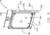
本発明に関連する特徴事項は、詳細に説明され、本明細書の結論として特許請求の範囲に請求される。本発明の上述の、そして、その他の特徴及び利点は、添付図面を参照して、以下の好ましい実施態様の詳細な説明から容易に理解される。図1は、本発明を適用してなる柔軟な容器の斜視図である。図2は、フレームに収容された図1に示した柔軟な容器の斜視図である。図3は、フレーム内に収容されている図2に示したものより容量の小さい、本発明を適用してなる柔軟な容器の別の例の斜視図である。図4は、図2に示した柔軟な容器を保持するフレームの別の例の斜視図であり、フレームは足部材を有する。図5は、図2に示したフレーム及び柔軟な容器を収容する温度制御ユニットの斜視図である。図6は、図5に示した温度制御ユニットの側方断面図である。 Features relating to the invention will be described in detail and claimed in the claims as a conclusion of the specification. The above and other features and advantages of the present invention will be readily understood from the following detailed description of the preferred embodiments with reference to the accompanying drawings. FIG. 1 is a perspective view of a flexible container to which the present invention is applied. FIG. 2 is a perspective view of the flexible container shown in FIG. 1 housed in a frame. FIG. 3 is a perspective view of another example of a flexible container to which the present invention is applied, having a smaller capacity than that shown in FIG. 2 housed in a frame. FIG. 4 is a perspective view of another example of a frame that holds the flexible container shown in FIG. 2, and the frame has a foot member. FIG. 5 is a perspective view of a temperature control unit that accommodates the frame and the flexible container shown in FIG. 6 is a side sectional view of the temperature control unit shown in FIG.
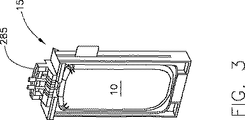
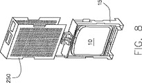
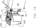
図7は、保護カバー中に収容可能な、図2に示したフレーム及び柔軟な容器の斜視図である。図8は、保護カバー中に収容可能な、図4に示したフレーム及び柔軟な容器の斜視図である。図9は、積み重ねられている図8に示した保護カバー中に収容された複数の柔軟な容器及びフレームの斜視図である。図10は、柔軟な容器に接続可能な排出管を収容するためのチャンネルを示す図2のフレーム及び柔軟な容器の斜視図である。図11は、図10のチャンネル内に収容可能な排出管に接続された、図2の柔軟な容器の斜視図である。図12は、柔軟な容器とフレームの上部の間の空洞に収容可能な排出管を含む図2のフレーム及び柔軟な容器の斜視図である。図13は、図2のフレーム及び柔軟な容器を各1つ以上運搬するためのカート装置の斜視図である。図14は、図5の温度制御ユニットに隣接した図13のカートであって、それらの間で図2のフレームを運搬するためのカートの斜視図である。 7 is a perspective view of the frame and flexible container shown in FIG. 2 that can be accommodated in a protective cover. FIG. 8 is a perspective view of the frame and flexible container shown in FIG. 4 that can be housed in a protective cover. 9 is a perspective view of a plurality of flexible containers and frames housed in the protective covers shown in FIG. 8 being stacked. FIG. 10 is a perspective view of the frame and flexible container of FIG. 2 showing a channel for receiving a drain tube connectable to the flexible container. 11 is a perspective view of the flexible container of FIG. 2 connected to a drain tube that can be received in the channel of FIG. 12 is a perspective view of the frame and flexible container of FIG. 2 including a drain tube that can be received in a cavity between the flexible container and the top of the frame. FIG. 13 is a perspective view of a cart apparatus for carrying one or more of the frame and the flexible container of FIG. 14 is a perspective view of the cart of FIG. 13 adjacent to the temperature control unit of FIG. 5 for carrying the frame of FIG. 2 between them.
図15は、本発明を適用してなるモジュール構造のフレームに収容可能な生物薬剤材料の収容用の柔軟な容器の別の実施形態の組立分解図。図16は、図15の柔軟な容器の斜視図である。図17は、図15のフレームの上部ハンドルに接続された図15の柔軟な容器の斜視図である。図18は、図15のフレーム内に収容された柔軟な容器の斜視図である。図19は、フレームの取付けボスに接続されている柔軟な容器の取付けループを示す図15のフレームの一部の斜視図である。 FIG. 15 is an exploded view of another embodiment of a flexible container for containing biopharmaceutical material that can be contained in a modular frame to which the present invention is applied. 16 is a perspective view of the flexible container of FIG. 17 is a perspective view of the flexible container of FIG. 15 connected to the upper handle of the frame of FIG. 18 is a perspective view of a flexible container housed in the frame of FIG. 19 is a perspective view of a portion of the frame of FIG. 15 showing the flexible container attachment loop connected to the attachment boss of the frame.
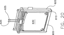
図20は、本発明を適用してなる、クランピングフレーム内に収容されている生物薬剤材料の貯蔵及び凍結用の柔軟な容器のさらに別の実施形態の斜視図である。図21は、柔軟な容器がフレーム内に配置されているオープンポジションの図20の柔軟な容器及びフレームの斜視図である。図22は、旋回面が閉じられている図20の柔軟な容器及びフレームの斜視図である。 FIG. 20 is a perspective view of yet another embodiment of a flexible container for storage and freezing of biopharmaceutical material contained within a clamping frame, to which the present invention is applied. 21 is a perspective view of the flexible container and frame of FIG. 20 in the open position with the flexible container disposed within the frame. 22 is a perspective view of the flexible container and frame of FIG. 20 with the swivel surface closed.
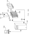
図23は、本発明を適用してなる柔軟な容器が支持ロッドを収容している生物薬剤材料の貯蔵及び凍結用柔軟な容器のさらにまた別の実施形態の斜視図である。図24は、種々の容量の柔軟な容器を収容するための各種支持ロッドの斜視図である。図25は、生物薬剤材料の貯蔵及び凍結用の複数の柔軟な容器のスリーブに収容されている図24の支持ロッドの1つの斜視図である。図26は、本発明を適用してなる保護カバー内に収容されている図23の柔軟な容器の斜視図である。図27は、1つ以上の柔軟な容器を運搬するためのカート装置に収容されている図24の柔軟な容器及び支持ロッドの斜視図である。図28は、図23の柔軟な容器及び支持ロッドが図27のカートに収容されている図27の一部の拡大斜視図である。 FIG. 23 is a perspective view of yet another embodiment of a flexible container for storage and freezing of biopharmaceutical material wherein a flexible container to which the present invention is applied contains a support rod. FIG. 24 is a perspective view of various support rods for accommodating flexible containers of various capacities. 25 is a perspective view of one of the support rods of FIG. 24 housed in a sleeve of a plurality of flexible containers for storage and freezing of biopharmaceutical material. FIG. 26 is a perspective view of the flexible container of FIG. 23 housed in a protective cover to which the present invention is applied. FIG. 27 is a perspective view of the flexible container and support rod of FIG. 24 housed in a cart apparatus for carrying one or more flexible containers. 28 is an enlarged perspective view of a portion of FIG. 27 with the flexible container and support rod of FIG. 23 housed in the cart of FIG.
図29は、本発明を適用してなる柔軟な容器のスリーブに収容されている支持ロッド及び柔軟な容器運搬用カートの支持部材上に収容されている支持ロッドの別の実施形態の斜視図である。図30は、容器を満たすための状態にされた図20のフレーム及び柔軟な容器の側面図である。図31は、容器からの排出を行うための状態にされた図20のフレーム及び柔軟な容器の側面図である。図32は、容器からの排出を行うための状態にされた図20の柔軟な容器及びフレームの側面図である。 FIG. 29 is a perspective view of another embodiment of a support rod housed in a flexible container sleeve to which the present invention is applied and a support rod housed on a support member of a flexible container transport cart. is there. 30 is a side view of the frame and flexible container of FIG. 20 ready to fill the container. FIG. 31 is a side view of the frame of FIG. 20 and the flexible container in a state for discharging from the container. FIG. 32 is a side view of the flexible container and frame of FIG. 20 ready for draining from the container.
図33は、本発明を適用してなる生物薬剤材料を凍結、貯蔵及び解凍するシステムの別の実施形態のブロック図である。図34は、組み立て前の図33のシステムに使用可能な柔軟な容器の形状の生物薬剤材料の貯蔵及び凍結用の容器の各部分の斜視図である。図35は、溶着された後の図34の柔軟な容器の部品の斜視図である。図36は、組み立て後の図35の柔軟な容器の斜視図である。 FIG. 33 is a block diagram of another embodiment of a system for freezing, storing and thawing a biopharmaceutical material to which the present invention is applied. FIG. 34 is a perspective view of portions of a container for storage and freezing of biopharmaceutical material in the form of a flexible container that can be used in the system of FIG. 33 prior to assembly. FIG. 35 is a perspective view of the flexible container components of FIG. 34 after being welded. 36 is a perspective view of the flexible container of FIG. 35 after assembly.
図37は、滅菌した柔軟な容器、及び本発明と併せて使用可能な硬質ホルダーを含む生物薬剤材料の貯蔵及び凍結用の容器の別の実施形態の斜視図である。図38は、生物薬剤材料の収容用の柔軟な容器を収容するための図33に示したシステムに使用可能な貯蔵機構の側面図である。図39は、図38の貯蔵機構の端面図である。図40は、図38の貯蔵機構の断面図である。図41は、図39の端面図の断面図である。図42は、さらに流路を含む図38の貯蔵機構の端面図である。 FIG. 37 is a perspective view of another embodiment of a container for storage and freezing of biopharmaceutical material comprising a sterile flexible container and a rigid holder that can be used in conjunction with the present invention. FIG. 38 is a side view of a storage mechanism that can be used in the system shown in FIG. 33 for containing a flexible container for containing biopharmaceutical material. FIG. 39 is an end view of the storage mechanism of FIG. 40 is a cross-sectional view of the storage mechanism of FIG. 41 is a cross-sectional view of the end view of FIG. 42 is an end view of the storage mechanism of FIG. 38 further including a flow path.
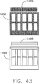
図43は、生物薬剤材料の収容用の柔軟な容器を収容するための図33に示したシステムに使用可能な貯蔵機構の別の実施形態の2つの複製品の側面図である。図44は、図43の貯蔵機構の端面図である。図45は、図44の貯蔵機構の側方断面図である。図46は、内部に図33の柔軟な容器を収容している図44の貯蔵機構の側面図である。図47は、折り畳まれている図44の貯蔵機構の斜視図である。図48は、本発明を適用してなる生物薬剤材料の収容用の複数の柔軟な容器の温度を調節するためのシステムのブロック図である。図49は、複数の柔軟な容器が挿入されるテーパー状の内部を有する図48のシステムの一部の側方断面図である。図50は、柔軟な容器が温度制御ユニットに挿入される上部板と一体化して構成される図48のシステムの側方断面図である。図51は、本発明を適用してなる上部板と一体化して構成される柔軟な容器の一部の側方断面図である。 FIG. 43 is a side view of two replicates of another embodiment of a storage mechanism that can be used in the system shown in FIG. 33 for containing a flexible container for containing biopharmaceutical material. 44 is an end view of the storage mechanism of FIG. 45 is a side cross-sectional view of the storage mechanism of FIG. FIG. 46 is a side view of the storage mechanism of FIG. 44 containing the flexible container of FIG. 33 therein. 47 is a perspective view of the storage mechanism of FIG. 44 being folded. FIG. 48 is a block diagram of a system for adjusting the temperature of a plurality of flexible containers for containing biopharmaceutical materials to which the present invention is applied. 49 is a side cross-sectional view of a portion of the system of FIG. 48 having a tapered interior into which a plurality of flexible containers are inserted. FIG. 50 is a side cross-sectional view of the system of FIG. 48 configured with a flexible container integrated with an upper plate inserted into the temperature control unit. FIG. 51 is a side sectional view of a part of a flexible container configured integrally with an upper plate to which the present invention is applied.
図52は、本発明を適用してなる温度制御ユニットに収容されている生物薬剤材料の収容用の柔軟な容器の別の実施形態の側方断面図である。図53は、図52の柔軟な容器及び温度制御ユニットの上面図である。図54は、さらに柔軟な容器の上部が連続的な壁に溶着されている図52の柔軟な容器の一部の側方断面図である。図55は、本発明を適用してなる温度制御ユニットに収容可能な複数の柔軟な容器を備えた生物薬剤材料の貯蔵用のシステムの別の実施形態の側方断面図である。 FIG. 52 is a side sectional view of another embodiment of a flexible container for containing biopharmaceutical material contained in a temperature control unit to which the present invention is applied. 53 is a top view of the flexible container and temperature control unit of FIG. 54 is a side cross-sectional view of a portion of the flexible container of FIG. 52 with the upper portion of the more flexible container welded to a continuous wall. FIG. 55 is a side sectional view of another embodiment of a system for storing biopharmaceutical material comprising a plurality of flexible containers that can be accommodated in a temperature control unit to which the present invention is applied.
本発明の原理にしたがって、生物薬剤材料を凍結、保存及び貯蔵するためのシステム及び方法が提供される。 In accordance with the principles of the present invention, systems and methods are provided for freezing, preserving and storing biopharmaceutical materials.
細胞のような生物薬剤材料を低温保存するために処理する場合、例えば、細胞の凍結速度が速すぎ、含水量が高すぎると、細胞内に氷晶が生じることがある。その結果、細胞は破裂及び生存不可能の少なくとも一方の状態となる。これに対して、細胞の凍結速度が遅すぎる場合には、細胞は、長時間にわたって高濃度の溶質にさらされることになり、これが細胞の損傷を引き起こすこともある。 When processing a biopharmaceutical material such as a cell for cryopreservation, for example, if the freezing rate of the cell is too fast and the water content is too high, ice crystals may form in the cell. As a result, the cell becomes at least one of ruptured and non-viable. In contrast, if the freezing rate of the cells is too slow, the cells will be exposed to a high concentration of solute for an extended period of time, which may cause cell damage.
凍結速度は、有害な影響をもたらす生物薬剤材料の不均一な分布で、凍結した容積内で生物薬剤材料の分布に影響する場合がある。一実施形態において、冷却された壁から生物薬剤材料の大部分の領域へと樹枝状凍結境界面が進行するので、凍結速度の制御は、樹枝状凍結境界面速度の制御として表すことができる。また、凍結速度は、生物薬剤材料の保護特性、または、生物薬剤材料の損傷特性を有する最終的な凍結した基質にも影響を与える。 Freezing rate is an uneven distribution of biopharmaceutical material that has deleterious effects and may affect the distribution of biopharmaceutical material within a frozen volume. In one embodiment, the control of the freezing rate can be expressed as the control of the dendritic freezing interface velocity, as the dendritic freezing interface proceeds from the cooled wall to the majority of the area of the biopharmaceutical material. Freezing rate also affects the final frozen substrate that has the protective properties of biopharmaceutical material or the damaging properties of biopharmaceutical material.
例えば、樹枝状氷晶間のガラス質状部分に生物薬剤材料が埋め込まれている状態の凍結した基質は、生物薬剤材料を保護するタイプである。生物薬剤材料を損傷する基質は、異なる形をとる。例として、(1)非常に緻密な細胞氷晶基質、または、(2)非常に多数の微細氷晶の集合であって、生成物が結晶境界に沿った非常に薄い層に位置する基質がある。凍結した基質の特性は、氷晶構造に依存し、好ましい構造は、樹枝状氷晶構造である。このような所望の基質構造は、主として凍結境界面速度に依存し、その他の二次的に重要な要因は、温度勾配、溶質の組成と濃度、そして、凍結容器の形状である。 For example, a frozen substrate in which the biopharmaceutical material is embedded in the glassy portion between dendritic ice crystals is a type that protects the biopharmaceutical material. Substrates that damage biopharmaceutical materials take different forms. Examples include (1) a very dense cell ice crystal substrate, or (2) a collection of a very large number of fine ice crystals where the product is located in a very thin layer along the crystal boundary. is there. The characteristics of the frozen substrate depend on the ice crystal structure, and the preferred structure is a dendritic ice crystal structure. Such desired substrate structure depends primarily on the freezing interface velocity, and other secondary important factors are temperature gradient, solute composition and concentration, and the shape of the cryocontainer.
本発明により、樹枝状氷晶の凍結境界面(以後、「樹枝状凍結境界面」と称する)の速度を約5ミリメータ/時間から約250ミリメータ/時間の範囲、より好ましくは約8ミリメータ/時間から約180ミリメータ/時間の範囲、または、最も好ましくは約10ミリメータ/時間から約125ミリメータ/時間の範囲に維持することが、生物薬剤材料に対する損傷を最小にし、または、回避するための、広範囲のシステムに好適な冷凍処理条件、そして、適した作動マージンをもたらす。 According to the present invention, the speed of the freezing interface of dendritic ice crystals (hereinafter referred to as “dendritic freezing interface”) ranges from about 5 millimeters / hour to about 250 millimeters / hour, more preferably about 8 millimeters / hour. A range from about 180 millimeters / hour to about 180 millimeters / hour, or most preferably from about 10 millimeters / hour to about 125 millimeters / hour to minimize or avoid damage to the biopharmaceutical material. Provides suitable refrigeration processing conditions and a suitable operating margin for this system.
一例として、以下の説明は、生物薬剤材料の凍結に関して、樹枝状凍結境界面と凍結樹枝状結晶の大きさ及び間隔との関連性を示すものである。 As an example, the following description shows the relationship between the dendritic freezing interface and the size and spacing of the frozen dendrites with respect to freezing of the biopharmaceutical material.
樹枝状凍結境界面の速度が約5ミリメータ/時間より遥かに小さい場合、樹枝状結晶は小さく、樹枝状凍結境界面に密にかたまっている。したがって、樹枝状凍結境界面は、固体界面として振る舞い、溶質及び生物薬剤材料類は、その固形塊に一体化せず、その代わり、排除され、滅菌した柔軟な容器の中央部に向かって押され、生物薬剤材料の液相に深刻な凍結濃縮を引き起こす。 If the speed of the dendritic freezing interface is much less than about 5 millimeters / hour, the dendritic crystals are small and densely packed into the dendritic freezing interface. Thus, the dendritic freezing interface behaves as a solid interface and solutes and biopharmaceutical materials do not integrate into the solid mass, but are instead eliminated and pushed toward the center of the sterilized flexible container. Cause severe freeze concentration in the liquid phase of the biopharmaceutical material.
樹枝状凍結境界面の速度が増加したが、樹枝状凍結境界面の速度が約5ミリメータ/時間未満であるとき、樹枝状結晶はサイズが幾らか大きくなり、さらに分離して、セル形状または円柱形状になる。この場合、溶質または生物薬剤材料のほんのわずかなパーセンテージだけが固形塊に埋め込まれる。これに対して、大部分の溶質及び生物薬剤材料は、前進する樹枝状凍結境界面によって前方に押され、液相の生物薬剤材料110の濃度が高くなる。この状況では、まだ生物薬剤材料に損傷が起こることがある。
Although the speed of the dendritic freezing interface has increased, but when the speed of the dendritic freezing interface is less than about 5 millimeters / hour, the dendritic crystals are somewhat larger in size and further separated into cell shapes or cylinders Become a shape. In this case, only a small percentage of the solute or biopharmaceutical material is embedded in the solid mass. In contrast, most solutes and biopharmaceutical materials are pushed forward by the advancing dendritic freezing interface, increasing the concentration of the liquid phase
樹枝状凍結境界面の速度が増加したが、樹枝状凍結境界面の速度が約5ミリメータ/時間未満であるとき、樹枝状結晶はサイズが幾らか大きくなり、さらに分離して、セル形状または円柱形状になる。この場合、溶質または生物薬剤材料のほんのわずかなパーセンテージだけが固形塊に埋め込まれ得る。これに対して、大部分の溶質及び生物薬剤材料は、前進する樹枝状凍結境界面によって前方に押され、液相の生物薬剤材料110の濃度が高くなる。この状況では、まだ生物薬剤材料に損傷が起こることがある。
Although the speed of the dendritic freezing interface has increased, but when the speed of the dendritic freezing interface is less than about 5 millimeters / hour, the dendritic crystals are somewhat larger in size and further separated into cell shapes or cylinders Become a shape. In this case, only a small percentage of the solute or biopharmaceutical material can be embedded in the solid mass. In contrast, most solutes and biopharmaceutical materials are pushed forward by the advancing dendritic freezing interface, increasing the concentration of the liquid phase
樹枝状凍結境界面の速度が約250ミリメータ/時間より増加すると、樹枝状結晶の大きさは小さくなり始め、より緻密になり、これによって、生物薬剤材料に含まれる溶質や粒子を凍結境界面に適切に埋め込む能力が失われる。 As the speed of the dendritic freezing interface increases above about 250 millimeters / hour, the size of the dendritic crystals begins to decrease and becomes more dense, thereby bringing solutes and particles contained in the biopharmaceutical material into the freezing interface. The ability to embed properly is lost.
樹枝状凍結境界面速度が約250ミリメータ/時間より遥かに大きくなると、生成する固形塊は、微細な氷晶の無秩序で非平衡状態の構造を有するようになる。このような速やかな極低温冷却は、例えば少量の生物薬剤材料を過冷却することによって、薄い層での生物薬剤材料の凍結によって、または、少量の生物薬剤材料を液体窒素またはその他の冷媒中に沈めることによって行うことができる。 When the dendritic freezing interface velocity is much greater than about 250 millimeters / hour, the resulting solid mass will have a disordered, non-equilibrium structure of fine ice crystals. Such rapid cryogenic cooling can be achieved, for example, by supercooling a small amount of biopharmaceutical material, by freezing the biopharmaceutical material in a thin layer, or by placing a small amount of biopharmaceutical material in liquid nitrogen or other refrigerant. Can be done by submerging.
例えば、液相において過冷却にさらされ、その後、急速に氷晶が成長した生物薬剤材料では、凍結境界面の速度は、1000mm/secを超えることがある。このように速い境界面速度は、生物薬剤材料を含む固形塊を生成し得るが、その固形塊は、平衡状態の氷晶から形成されてはいない。これらの非平衡状態の固形塊では、氷の再結晶が起きがちであり、その際、比較的小さい氷晶の溶解及び比較的大きい氷晶の成長が生物薬剤材料に過度の機械的力を加える可能性がある。さらに、非平衡状態の固形塊中の生物薬剤材料は、氷晶間に、粒子境界上の非常に薄い層となって分布する。これは非常に多数の小氷晶による生成物と氷との大きな接触界面領域を作り出し、生物薬剤材料にとって有害である。 For example, in a biopharmaceutical material that has been subjected to supercooling in the liquid phase and then rapidly grown ice crystals, the freezing interface speed may exceed 1000 mm / sec. Such high interface speeds can produce a solid mass containing the biopharmaceutical material, but the solid mass is not formed from equilibrium ice crystals. In these non-equilibrium solid masses, ice recrystallization tends to occur, with relatively small ice crystal dissolution and relatively large ice crystal growth adding excessive mechanical force to the biopharmaceutical material. there is a possibility. Furthermore, the biopharmaceutical material in the non-equilibrium solid mass is distributed between ice crystals as a very thin layer on the particle boundary. This creates a large contact interface area between the product and ice from a very large number of small ice crystals and is detrimental to biopharmaceutical materials.
樹枝状結晶間の隙間は、システムから出る熱の増減によって(熱の増減は、熱効果に影響を与え、その結果、樹枝状凍結境界面の速度にも影響を与える)、また、溶質の選択及び濃度によって調節できる。 The gap between the dendrites depends on the increase or decrease of the heat coming out of the system (the increase or decrease of the heat affects the thermal effect and consequently also the speed of the dendritic freezing interface), and also the choice of solute And can be adjusted by concentration.
自由樹枝状結晶(free dendrites)の長さは、一つには境界面速度によって、そして、一つには樹枝状結晶に沿った温度勾配によって決まる。自由樹枝状結晶では、液相に突き出した樹枝状結晶の長さ、または、「どろどろした領域(mushy zone)」または「2層領域」の厚さ、例えば、樹枝状針状氷晶とそれらの間にある液相との混合物の厚さが関係する。樹枝状結晶の先端では、温度は0℃に近く、樹枝状結晶の長さに沿って、または、境界面から離れた固形化物になるほど、温度は徐々に低下して壁温と等しくなる。樹枝状結晶間の液体温度も、低温の壁に近くなるほど低下する。極低温冷却(cryocooling)が続くと、塩類のようなある種の溶質では溶質濃度が共晶濃度及び温度に達する。 The length of free dendrites is determined in part by the interface velocity and in part by the temperature gradient along the dendrite. In free dendrites, the length of the dendrites protruding into the liquid phase, or the thickness of a “mushy zone” or “bilayer”, eg dendritic acicular ice crystals and their The thickness of the mixture with the liquid phase in between is related. At the tip of the dendrite, the temperature is close to 0 ° C., and the temperature gradually decreases and becomes equal to the wall temperature as the solidified material moves along the length of the dendrite or away from the boundary surface. The liquid temperature between the dendrites also decreases as the temperature approaches the cold wall. If cryocooling continues, the solute concentration reaches eutectic concentration and temperature for certain solutes such as salts.
樹枝状結晶間の溶液は、その後固化し、完全またはほぼ完全な、または、固体の樹枝状結晶状態になる。この状態は、樹枝状氷晶と、これら樹枝状氷晶間の共晶状態の固化溶質とのマトリックスである。ある溶質類(例えば炭水化物)は、共晶混合物を形成しない。その代わり、それらは、ガラス質状態を形成したり、樹枝状氷晶間で結晶化したりする。ガラス質状態は、生物薬剤材料を保護し、結晶状態は、生物薬剤材料に有害効果を与える可能性がある。樹枝状氷晶は、アール・ウィスニウスキー(R. Wisniewski)著、「生物薬剤系のための大規模冷凍保存システムの開発(Developping Large-Scale Cryopreservation Systems for Biopharmaceutical Systems)」、BioPharm、11巻(6号)、1998年、p.50−56、及び、アール・ウィスニウスキー(R. Wisniewski)著、「細胞、細胞成分及び生物学的溶液の大規模冷凍保存(Large Scale Cryopreservation of Cells, Cell Component, and Biological Solutions)」、BioPharm、11巻(9号)、1998年、p.42−61に詳細に記載されている。この全ては参考として本明細書に編入される。 The solution between the dendrites then solidifies into a complete, almost complete, or solid dendritic state. This state is a matrix of dendritic ice crystals and eutectic solidified solutes between these dendritic ice crystals. Certain solutes (eg, carbohydrates) do not form a eutectic mixture. Instead, they form a vitreous state or crystallize between dendritic ice crystals. The vitreous state protects the biopharmaceutical material, and the crystalline state can have deleterious effects on the biopharmaceutical material. Dendritic ice crystals are written by R. Wisniewski, “Developing Large-Scale Cryopreservation Systems for Biopharmaceutical Systems”, BioPharm, Volume 11 ( 6), 1998, p. 50-56, and R. Wisniewski, “Large Scale Cryopreservation of Cells, Cell Component, and Biological Solutions), BioPharm, 11 (9), 1998, p.42-61. All this is incorporated herein by reference.
図1−6に示した一例の実施形態において、生物薬剤材料の冷却、凍結、保存、処理、運搬、解凍及び貯蔵のためのシステムの各部分が示される。本システムは、生物薬剤材料を収容するのに用いられ、そして、フレーム15のような支持構造体により支持されることで用いられる柔軟な容器10のような滅菌した容器を備えることができる。また、柔軟な容器10及びフレーム15は、温度制御ユニット20、運搬装置290(図13及び図14)及び貯蔵ユニットの少なくとも1つに受容されて用いられる。
In the example embodiment shown in FIGS. 1-6, portions of a system for cooling, freezing, storing, processing, transporting, thawing and storing biopharmaceutical material are shown. The system can be used to contain biopharmaceutical material and can comprise a sterile container such as a
例えば、 柔軟な容器10は、例えば、複数の層を有するラミネートフィルムで形成され、そして、0.01−100リットルの内部容積を有している。さらに、柔軟な容器10は、種々の用途に対応するために様々な大きさのものが利用可能であり、例えば5、10及び20リットルの柔軟な容器を利用することができる。また、柔軟な容器10内側の生体適合性のプロダクト接触層は、例えば、低密度ポリエチレン、超低密度ポリエチレン、エチレン酢酸ビニル共重合体、ポリエステル、ポリアミド、ポリ塩化ビニル、ポリプロピレン、ポリフルオロエチレン、ポリフッ化ビニリデン、ポリウレタンまたはフルオロエチレンプロピレンなどで形成されている。ガス及び水蒸気のバリア層は、ポリアミドまたはエチレン酢酸ビニル共重合体と、エチレン/ビニルアルコール共重合体との混合物で形成されている。
For example, the
さらに、柔軟な容器10は、機械的強度の高い層(例えば、ポリアミド)、例えば、ポリエステルなどの熱溶着に対して断熱効果のある外層を含んでいる。これらの層は、高温状態や低温状態に適合し、滅菌目的のイオン照射に耐えうる。また、柔軟な容器10は、容積に対して表面積を大きくし、壁を比較的薄くすることにより、温度制御ユニット20内に受容されたときの熱移動を促進している。柔軟な容器10を作製するのに有用な材料の一例がバロット(Vallot)の米国特許第5,988,422号に開示されており、これが参照されて本明細書に組み込まれる。また、柔軟な容器10は、使い捨てとすることで、使い勝手をよくすると共に、他のタイプの容器の再使用で生じる柔軟な容器10内でのクロスコンタミネショーンを防止することができる。
Further, the
滅菌した柔軟な容器10は、この柔軟な容器10を支持するためのフレーム15に受容されて用いられる。例えば、柔軟な容器10は、図1−図3に示したように、フレーム15のチャンネル200に受容されるのに用いられる外側に伸びるフランジ100を有している。例えば、フランジ100は、チャンネル200に受容される大きさのプラスチック製の強化ロッドである。したがって、フランジ100つまり柔軟な容器10は、下方へ垂直に挿入したり、上方へ垂直に取り外したりすることができるが、フランジ100とチャンネル200との結合により、横方向または上下以外の方向には動かせない。このように、フランジ100は、柔軟な容器10の三方の側部すなわち両側部及び底部に沿って、そこにかかる負荷を分散させることにより、柔軟な容器10を横方向に対して支持し、充填中の柔軟な容器10の形状を維持し、容器10のたるみを抑え、そして、柔軟な容器10の寸法を確実に安定させるのに役立つ。
The sterilized
さらに、柔軟な容器10は、柔軟な容器10の上部から突き出て垂直に伸びるフランジまたはロッド(図示していない)を設けることができる。この垂直に伸びるフランジは、チャンネル200に受容される構造で、フランジ100に対してほぼ直角にする。また、この垂直に伸びるフランジは、柔軟な容器10をフレーム15に収容したときの柔軟な容器10のたるみを抑えるため、フレーム15の上部に結合する作りとすることができる。
Furthermore, the
また、柔軟な容器10は、柔軟な容器10の内容物を使用者に示すラベルを取り付けるためのタブ110や、その他の手段を有することもできる。このようなラベルは、内容物の確認、追跡及び説明の少なくとも1つを容易にするのに、柔軟な容器10の内容物を示すための記載情報、埋め込み式マイクロチップ、RFトランスミッタ及び電子または磁気バーコードの少なくとも1つを設け含んでいる。したがって、ラベルの使用は、柔軟な容器10を、他の似たようなフレームや柔軟な容器を収容している大きなフリーザに貯蔵するとき、フレーム15に収容した柔軟な容器10に貯蔵した材料の管理を簡素化する。
The
柔軟な容器10は、図2に示したように、生物薬剤材料、または、他の固体、液体またはガスを柔軟な容器10の内部(図示していない)へ充填及び外へ排出することの少なくとも一方を可能にするため、1つ以上のポートまたは流路120を有している。また、流路120は、柔軟な容器10内に測定用プローブ(図示していない)を挿入するのにも用いられる(例えば、pH電極、伝導度センサ、温度プローブ、イオン選択性電極、分光光度プローブ、超音波センサ、光ファイバ)。流路120は、柔軟な容器10の上部及び底部の少なくとも一方に配置することができる。
The
このような流路の配置は、容器の充填及び排出の少なくとも一方を容易にする。流路120は、柔軟な容器10と一体にするか、または、受容ポート(図示していない)に接続可能なものとする。例えば、流路120は、入口ポート内に配設されたフィッティングを用いて受容ポートに接続することができる。米国特許第6,186,932号に開示されているようなフィッティングが、この種の流路の接続に用いることができる。また、容器または柔軟な容器の内容物の滅菌性を維持することができるフィッティングが用いられることが好ましい。これらのフィッティングは、必要に応じて、ストレートフィッティング及び90度エルボなどのアングルフィッティングの少なくとも一方のような様々な形状で形成される。別の例では、流路120は、生物薬剤材料から不純物やその他の好ましくない物質を除去するためのフィルタ(図示していない)を有している。
Such a flow path arrangement facilitates at least one of filling and discharging the container. The
温度制御ユニット20は、図5−図6に示したように、その内部25の温度を調節する構造になっている。また、柔軟な容器10を温度制御ユニット20の内部25中に入れたとき、使用者が、例えば、この容器の中の生物薬剤材料の加熱、冷却、凍結または解凍を制御することを可能にするため、温度制御ユニット20は、制御装置を内蔵されるか、または、これに接続される。温度制御ユニット20内に設置された柔軟な容器10の内容物の加熱、冷却、凍結または解凍は、例えば、連続的に冷気または暖気を吹き込むことか、容器を冷たい表面または温かい表面と直接接触させることか、または、冷却液(例えば、液体窒素)を噴霧することなどにより制御される。
As shown in FIGS. 5 to 6, the
好ましい実施形態において、温度制御ユニット20は、図5−図6に示したように、柔軟な容器10及びこれに収容された生物薬剤材料を加熱及び冷却の少なくとも一方を行なうための1以上の伝熱板を有する熱交換器である。例えば、温度制御ユニット20は、柔軟な容器10に接触させてその内容物を冷却するための伝熱板28を含んでいる。また、1以上の伝熱板28は、柔軟な容器10がフレーム15に受容され、フレーム15が温度制御ユニット20の内部25に受容されているときに、柔軟な容器10の圧縮が可能なように、可動になっている。さらに、温度制御ユニット20は、図6に示したように、柔軟な容器10がフレーム15に受容され、フレーム15が温度制御ユニット20の内部25に受容されているときに、柔軟な容器10を圧縮する構造になっている伝熱板28とは別に、1以上の温度制御されていない壁(図示していない)を含むこともできる。
In a preferred embodiment, the
例えば、温度制御ユニット20は、ポート120から容器10内に挿入するか、または、伝熱板28と結合または一体化することができる1以上の温度センサ(図示していない)からの生物薬剤材料に関するフィードバック温度データによって、生物薬剤材料内の樹枝状凍結面(図示していない)速度の割合を制御する。このフィードバックループは、生物薬剤材料からの熱除去のさらに正確な制御を行い、樹枝状凍結面速度を前記で列挙した範囲内に調節するのを容易にする。滅菌した柔軟な容器10の壁厚、フレーム15の厚さ、滅菌した柔軟な容器10と伝熱板28との間の熱抵抗などの変量は、このフィードバックループによって自動的に計算に組み込まれる。
For example, the
樹枝状凍結境界面は、固形塊として存在する生物薬剤材料を、液体状の生物薬剤材料から分離し、それによって樹枝状結晶が形成されつつある固体−液体界面が生じる。生物薬剤材料からの熱除去が続くと、樹枝状凍結境界面は、滅菌した柔軟な容器10の内面から離れる方向に進み、残りの液体生物薬剤材料は凍結して固形塊になる。本発明の実施形態では、樹枝状凍結境界面の速度とは、樹枝状凍結境界面が進む速度である。
The dendritic freezing interface separates the biopharmaceutical material present as a solid mass from the liquid biopharmaceutical material, thereby creating a solid-liquid interface where dendrites are being formed. As heat removal from the biopharmaceutical material continues, the dendritic freezing interface proceeds away from the inner surface of the sterilized
一実施形態では、熱が生物薬剤材料から除去される速度(すなわち熱流束)が樹枝状凍結境界面の速度を決める。生物薬剤材料と伝熱板28との間の温度勾配は、熱が生物薬剤材料から除去される速度と相関するため、樹枝状凍結境界面の速度は、伝熱板28の温度をコントロールすることによって制御できる。
In one embodiment, the rate at which heat is removed from the biopharmaceutical material (ie, heat flux) determines the rate of the dendritic freezing interface. Because the temperature gradient between the biopharmaceutical material and the
好ましい実施形態では、熱は、生物薬剤材料から除去される速度は、生物薬剤材料の実質的な全容積内での樹枝状凍結境界面の実質的に均一な前進を促進する速度、または、樹枝状凍結境界面の実質的に一定の速度で生物薬剤材料から除去される。本発明の一実施形態によれば、滅菌した柔軟な容器10内の樹枝状凍結境界面の速度を実質的一定に維持することが好ましい。なぜならば、それは、冷凍する容積での冷却熱伝達面までの距離とは無関係に、樹枝状氷晶を円滑に成長させるための実質的に定常状態の条件をもたらすからである。
In a preferred embodiment, the rate at which heat is removed from the biopharmaceutical material is a rate that promotes a substantially uniform advance of the dendritic freezing interface within a substantially total volume of the biopharmaceutical material, or Is removed from the biopharmaceutical material at a substantially constant rate of the freezing interface. According to one embodiment of the present invention, it is preferable to maintain the speed of the dendritic freezing interface within the sterilized
フレーム15は、柔軟な容器10にさらに剛性を与え、支持するため、柔軟な容器10を受容し、支持する形状にされており、これにより、その取り扱い、貯蔵及び温度制御の少なくとも一方を容易にしている。フレーム15は、第1の開口部210、そして、フレーム15の開口部210と反対側の第2の開口部211(図6)を有している。これらの開口部は、柔軟な容器10の大きな表面積を温度制御ユニット20の内部25に曝す。これらの開口部によって、柔軟な容器10は、伝熱板28(図6)のような伝熱面、温度の調節された空気、または、温度制御ユニット20内の冷却噴霧液体に接触する。
The
例えば、柔軟な容器10の第1の側面12は、柔軟な容器10内の生物薬剤材料の温度を調節するため、開口部210を介して温度制御ユニット20(図5)の内部25の伝熱面(例えば、伝熱板28の1枚)と接触する。または、柔軟な容器10の側面12は、温度制御ユニット20内の静止または循環空気に曝される。例えば、柔軟な容器10がフレーム15に受容され、フレーム15が温度制御ユニット20に受容されているとき、生物薬剤材料は、柔軟な容器10に入れたままで凍結または解凍される。
For example, the
また、生物薬剤材料をほぼ一杯に充填し、そして、柔軟な容器10とフレーム15が温度制御ユニット20の内部25に受容されたとき、柔軟な容器10は、伝熱板28(図6)によって圧縮されて用いられる。さらに、柔軟な容器10の内容物は、寸法115と同じ方向におけるフレーム15の内部240の寸法または幅230以下であるフレーム15の第1の開口部210と第2の開口部211(図6)の間の方向における寸法または幅115を有する状態に柔軟な容器10をするため、伝熱板28によって温度制御ユニット20内で柔軟な容器10を圧縮している間に、凍結または固化される。したがって、その中に凍結された生物薬剤材料を有している柔軟な容器10は、フレーム15によって規定された包絡線または厚さ内に閉じ込められる。
Also, when the biopharmaceutical material is almost fully filled and the
フレーム15における柔軟な容器10の圧縮によって、長方形状の断面の輪郭が、その中に生物薬剤材料を有している柔軟な容器10に形成される。このような断面の輪郭は、柔軟な容器10と伝熱板28との間の接触を促進する。これは、特に柔軟な容器10の角部について言え、このため、伝熱板28に対して直角な方向に均一に進行しながら凍結するのを可能にする。さらに、柔軟な容器10の圧縮は、伝熱板28と柔軟な容器10との間のあらゆる空隙または空間を満たすよう柔軟な容器10内の生物薬剤材料を押す。このような空隙または空間を減少または最小化することによって、伝熱板28と柔軟な容器10との接触は、より均一化し、これにより、柔軟な容器10内に収容した生物薬剤材料のより均一な冷却をもたらす。
By compression of the
さらに、フレーム15は、柔軟な容器10を保護し支持するための、上方に伸びる側部260、底部270及び上部280を有している。上部280は、上部280を開くことができ、柔軟な容器10を内部240に挿入できるように、上部280を蝶番によりフレーム15に取り付けられており、そして、上部280は、柔軟な容器10を保護するために閉じられる。また、上部280は、図4に示したものが最も良いように、ハンドル285を有しており、そして、上部280は、側部260に脱着可能になっている。
In addition, the
したがって、使用者は、その中に収容した生物薬剤材料を収容できる柔軟な容器10と一緒またはなしでフレーム15を運ぶのにハンドル285を握ることができるように、上部280を側部260に結合する。フレーム15は、安定したままであり、その構造特性を維持する材料で形成されることが好ましい。詳細に言えば、この種の材料は、バイオ医薬製造においてよく用いられる洗浄剤及び方法(例えば、水酸化ナトリウム、次亜塩素酸ナトリウム(CLOROX)、過酢酸など)に耐性を有すると同時に、負荷耐性を維持し、マイナス80℃以下のガラス転移温度を示さなければならない。
Thus, the
例えば、側部260は、フルオロポリマー(すなわち、テフロン(登録商標))で形成され、上部280及び底部270は、ステンレススチールで形成される。また、側部260、底部270及び上部280の少なくとも1つは、例えばアルミニウム、ポリエチレン、ポリカーボネート及びポリスルホンなどを含む多くの他の材料でも形成される。さらに、材料としては、ガラス強化プラスチック、炭素繊維強化樹脂、または、高い荷重強度率を示すことが知られ、目的とする種々の温度で使用できる他のエンジニアリングプラスチックのような複合材料を含む。
For example, the
側部260、底部270及び上部280の少なくとも1つが、1つの部品として、または互いに適当に結合されて形成された一体式で各種の部分からなるものであることは、当業者によって理解されるであろう。さらに、側部260、底部270及び上部280の少なくとも1つは、同一材料(例えば、ステンレススチール)で形成されることができ、また、これらは、異なる材料で形成され、互いに結合されることができる。また、フレーム15は、図5に示したように、フレーム15を直立した状態に保つための足部材14も1以上有している。当業者によって理解されるように、足部材14は、フレーム15の1以上の側部260と一体化するか、または結合可能である。
It will be appreciated by those skilled in the art that at least one of the
さらに、フレーム15は、図7及び図8に示したように、柔軟な容器10を保護するための保護構造体またはカバー250に受容されることで用いられる。保護カバー250は、柔軟な容器10がフレーム15に収容されているとき、柔軟な容器10に穴が開いたり損傷したりすることから保護するため、開口部210及び第2の開口部211の少なくとも一方を覆う。さらに、柔軟な容器10、フレーム15及びカバー250が温度制御ユニット20(図5)またはウォークインフリーザのような別の制御された温度環境に受容されるとき、保護カバー250は、これを通じて熱伝達を容易にするための複数の開口255を有する。また、保護カバー250でフレーム15を覆うとき、開口255は、柔軟な容器10の内部を目で管理することを可能にする。
Further, the
保護カバー250で覆った2以上のフレーム15は、例えば図9に示したように、2以上を水平または垂直に積み重ねることができる。いずれの状態でも、積み重ねたケースの隣接面間の密な接触は、空気の通りを妨げないようにするため、ウェッジ(図示していない)により阻止される。この配置は、温度制御ユニット20の内部25が空気の対流効果によって冷却または加熱されているとき、温度の速やで、均一な制御のために都合がよい。また、保護カバー250は、さらに効果的な貯蔵及び取り扱いのため、液を充填した柔軟な容器を保護カバー250の内面により限定された厚さにまで平たくすることが可能である。さらに、カバー250は、図7及び図8からそれぞれ明らかなように、その上部または底部から柔軟な容器10を受容可能に形成されている。
Two or
また、フレーム15は、補助的な器具及び管類も有する。例えば、図10に示したように、フレーム15は、1以上の側部260及び底部270の少なくとも一方に、排出管282を通すためのチャンネル16を備えている(図10−図12)。柔軟な容器10は、チャンネル16に受容可能に形成された排出管282に接続されるか、または、一体化されており、排出管282は、図11に示したように、チャンネル16の水平部分及び垂直部分に対応する水平に伸びる部分286及び垂直に伸びる部分287を含んでいる。
The
コンパートメントまたは空洞19は、図12に示されたように、柔軟な容器10の上部11とフレーム15の上部280との間に配設されている。空洞19は、柔軟な容器10の内部からの排出に使用するまで排出管282を格納しておくために、排出管282を受容する。さらに、空洞19には、キャプスタン284を含み、この周囲に、格納のため、排出管282が巻きつけられる。空洞19は、ベントフィルタ、オンラインフィルタ、コネクタ及びサンプリングポートのような柔軟な容器の付属品(図示していない)を支持するためにもまた使用される。空洞19は、貯蔵及び運搬中のこれらの付属品の保護を可能にする。これらの付属品は、低温で脆くなるプラスチック製のものが多い。空洞19は、これらの付属品を安全な状態で保護し、これにより、付属品がフレーム15及び柔軟な容器10からはずれて損傷したり壊れたりするのを抑制する。
The compartment or
さらに、フレーム15は、図13−図14に示したように、貯蔵ユニットまたはカート290のような運搬装置に受容されて用いられる。例えば、フレーム15の幅230は、カート290にフレーム15を受容可能にするため、カート290のチャンネル297の寸法または幅295以下になっている。また、図5及び図13−図14に示したように、チャンネル297の底面298は、フレーム15を温度制御ユニット20の内部25に容易に滑り込ませることを可能にするため、温度制御ユニット20の内部25の底面と同一か同様の高さになっている。
Furthermore, the
さらに、温度制御ユニット20は、温度制御ユニット20の内部25にフレーム15を保持するための可動支持部材22をもまた有している。また、可動支持部材22は、この上に支持されたフレーム15と共に内部25の外側に引き出される。したがって、可動支持部材22は、フレーム15が可動支持部材22からカート290のチャンネル297の中に滑り込む点まで引き出される。また、チャンネル297は、チャンネル297内のフレーム15を支持するための1以上のチャンネル支持体292を有している。
Furthermore, the
また、温度制御ユニット20は、温度制御ユニット20の内部25の外側にフレーム15を引き出すためのフレーム引出機構を有することもでき、この機構は、図5に示したように、レバー23によって作動される。例えば、このフレーム引出機構は、レバー23の作動に応じて引き出される可動支持部材22を有する。したがって、温度制御ユニット20とカート290が互いに隣接して配置されているとき、フレーム15は、フレーム15を保持する可動支持部材22の動きによって、可動支持部材22の内部25からカート290へ容易に移動させられる。カート290は、1以上の柔軟な容器10を保持しているフレーム15の貯蔵中または運搬中の熱損失を低減するため、断熱壁を有している。加えて、柔軟な容器10に収容したバイオ医薬用プロダクトを液体または凍結状態で長期貯蔵するため、ウォークイン型、チェスト型またはキャビネット型のチラーまたはフリーザ(図示していない)が、フレーム15を受容するのに用いられるレールまたはチャンネル支持体(図示していない)を備えている。
Further, the
フレーム15は、決められた位置での柔軟な容器10の固定を確実に行なう。このような配置は、液体を充填した柔軟な容器10の取り扱い及び運搬を容易にする。特に、足部材14により支持されているとき、充填及び排出操作は、フレーム15によって支持された柔軟な容器10が自立した状態により、容易に行なわれる。これに代えて、柔軟な容器10は、フレーム15がカート290内に配置した柔軟な容器10を保持しているときに、充填されるか、排出されるか、または、それらの両方が行なわれる。従来は、充填された柔軟な容器に充填した液体は、重力によって排出される。柔軟な容器は、通常、完全な排出が行えるように、逆さまに吊るされるか、少なくとも傾斜させられる。この操作は、例えば10リッタを超える容量の柔軟な容器の場合、重量の制約により危険であるか、扱い難くいか、それら両方の状況になる。したがって、排出を容易にするため、自立したフレームに高容量の柔軟な容器を保持させることが望ましい。
The
本発明の別の実施形態では、中に生物薬剤材料を収容するための柔軟な容器350は、図15−19に示したように、柔軟な容器350を支持するためのフレーム360に受容されて用いられる。フレーム360は、互いに連結可能な左側部370、右側部380、低部390及び上部400を有している。柔軟な容器350は、フランジ405を有し、そして、フレーム360は、フレーム360の上部400から左側部370及び右側部380に対しほぼ直角な方向に外側へ突出した1以上の突起またはポスト420を有している。フランジ405は、1以上のポスト420を受容する寸法の1以上の開口410を有している。具体的に言えば、この1以上のポスト420は、1以上の開口410から挿入され、したがって、ポスト420は、フランジ405、ひいては、柔軟な容器350とその中のあらゆる内容物を支持する。
In another embodiment of the invention, a
さらに、1以上のキャプチャフランジまたは部材430は、上部400に取り付けられており、柔軟な容器350の方に蝶番によって回転可能になっており、そして、1以上のポスト420を受容するのに用いられる。これにより、キャプチャ部材430が柔軟な容器350の方に回転され、これにポスト420が受容されると、ポスト420は、柔軟な容器350を垂直方向に支持すると同時に、キャプチャ部材430は、柔軟な容器350のフランジ405がポスト420に平行で上部400から離れる方向(例えば、水平方向)へ移動するのを抑制または阻止する。したがって、このような垂直方向の支持は、容器350のたるみを抑え、そして、上記のような水平方向の支持は、容器350が、例えばフレーム360からはずれて異物により損傷を受けることを抑制する。
In addition, one or more capture flanges or
また、柔軟な容器350は、例えば、右側部380の外面385及び左側部370の外面(図示していない)に、取付けボス460(図19)を介してフレーム15に結合可能な1以上の取付けループ450を有している。また、左側部370及び右側部380の少なくとも一方は、取付けループ450をこれに通して取付けボス460に取り付けるため、開口470(図15及び図19)を有している。取付けループ450を取付けボス460に結合することにより、柔軟な容器350は、その底面部分にしっかり嵌められ、これにより、例えば、柔軟な容器350がフレーム360からはずれ、異物により損傷または破壊されるのを抑制している。
Also, the
また、柔軟な容器350は、柔軟な容器350の内部(図示していない)から外、外から内部、または、その両方における、バイオ医薬用液体、その他の液体またはガスの注入または抽出を可能にするため、1以上のポートまたは流路355を有している。図15を参照すれば、柔軟な容器350の内容物に関する使用者に対するラベル(図示していない)またはその他の表示が柔軟な容器350に取り付けられているとき、フレーム360は、使用者がそのようなラベルまたはその他の表示を見ることができるように、半透明または透明な部分480を有している。このラベルは、例えば、記載情報、埋め込み式マイクロチップ、RFトランスミッタ及び電子または磁気バーコードの少なくとも1つを含むことができる。さらに、透明部分480は、例えば、光ファイバガイド/リーダーまたはウエーブガイドを含むこともできる。また、左側部370及び右側部380の少なくとも一方は、フレーム360を直立した状態に維持するための1以上の足部材490を有するように形成されている。当業者によって理解できるように、足部材490は、左側部370及び右側部380の少なくとも一方と一体化させるか、または、連結可能である。
The
生物薬剤材料をほぼ一杯に充填した柔軟な容器350または充填していない柔軟な容器350がフレーム360に受容されているとき、使用者が柔軟な容器350を持ち運ぶのを可能にするため、上部400は、ハンドル402を有している。また、上部400は、図11に示したように、柔軟な容器350を左側部370、右側部380または底部390に柔軟な容器350を連結することなしに、上部400で柔軟な容器350を支持できるようにするため、上部400は、柔軟な容器350に結合するのに用いられる。これにより、使用者は、上部400のみに連結した柔軟な容器350を持ち運ぶ。
To allow the user to carry the
本発明の別の実施形態では、フレーム600は、図20−図22に示したように、互いに連結または固定して用いるため、第1の部分610及び第2の部分620を有している。また、互いに連結することによって、第1の部分610及び第2の部分620は、これらの間に生物薬剤材料の収容用の柔軟な容器630をしっかり保持する。具体的に言えば、柔軟な容器630は、第1の部分610の内面615と第2の部分620の内面625との間に連結可能な1つ以上のフランジ660を有している。フランジ660は、第2の部分620の内面625から突出しているポスト670を受容するための1以上の開口665を有している。また、第1の部分610の内面615は、ポスト670に対応する1以上の開口を有している。
In another embodiment of the present invention, the
フランジ660は、第1の部分610と第2の部分620との間に受容されているとき、開口615へのポスト670を受容することは、フランジ660の移動を抑制し、そしてこれにより、柔軟な容器630の移動を抑制する。これにより、柔軟な容器630が、第1の部分610と第2の部分620との間に保持されると、ポスト670と共に第1の部分610及び第2の部分620によって柔軟な容器630の横方向及び垂直方向の支持がもたらされる。したがって、柔軟な容器630は、充填中にその形状を維持し、柔軟な容器のたるみの低減が実現され、そして、柔軟な容器630は、フレーム600によって規定された空間の包絡線内に収容される。
When the
柔軟な容器630は、この柔軟な容器630の内部(図示していない)に、内部から、または、その両方における、生物薬剤材料、その他の液体またはガスの充填や排出のため、1以上のポートまたは流路635を有している。また、柔軟な容器630は、フレーム600から突出しているタグまたはラベル680もまた有しており、このようなラベルまたはインジケータが柔軟な容器630に取り付けられているとき、柔軟な容器10の内容物を使用者に表示する。また、第1の部分610の旋回面612は、柔軟な容器630に生物薬剤材料がほとんど充填されていないとき、第1の部分610の底部614の上に柔軟な容器630を垂れ下げることができるように、開閉可能になっている。これは、柔軟な容器630は、充填中、柔軟な容器630のたるみやしわをできるだけ少なくするため伸展することが可能になる。柔軟な容器630が生物薬剤材料で満たされた後では、柔軟な容器630のいかなるしわも伸び、そして、柔軟な容器630は、底部614の上に垂れ下がらない。したがって、柔軟な容器630は、生物薬剤材料を満たしたとき、柔軟な容器630の底部分を何らかの外部の物体との接触から保護するため、旋回面612が閉じられる。
The
本発明の別の実施形態では、生物薬剤材料を収容するための柔軟な容器700は、図23−図25に示したように、柔軟な容器700を支持する支持部材720を収容するための1つ以上のスリーブ710を含んでいる。具体的に言えば、スリーブ710は、支持部材720を同軸に挿通することを可能とする寸法にされており、そして、支持部材720は、支持ロッド、または、ランス部725とグリップ部730を有している。また、グリップ部730は、柔軟な容器700が生物薬剤材料で満たされているとき、柔軟な容器700の重心の上に位置するように形成されている。柔軟な容器700は、例えば、柔軟な容器700が液状の生物薬剤材料で満たされているとき、使用者がグリップ部730を手で保持することによって運搬される。
In another embodiment of the present invention, a
さらに、図25に示したように、支持部材720は、柔軟な容器700を2つ以上支持するのに用いられる。また、図26に示したように、柔軟な容器700は、保護カバー750に受容される。保護カバー750は、柔軟な容器700の衝撃または破裂を抑制または防止するためのフォームライナーを内部に有している。また、保護カバー750は、柔軟な容器700を所望の温度に維持するため、断熱されている。さらに、柔軟な容器700は、保護カバー750の上部面755から突出しており、柔軟な容器700の内容物を示すため、ラベル110と同様なラベル760を有している。また、柔軟な容器700は、生物薬剤材料またはその他の材料をその中に注入したり、そこから除去したりするため、ポートまたは流路705を1以上有している。
Furthermore, as shown in FIG. 25, the
支持部材720は、図27−図28に示したように、例えば、この支持部材720が生物薬剤材料で満たされた柔軟な容器700を支持している状態で、貯蔵ユニット800に受容される。具体的に言えば、支持部材720の第1の端部722は、貯蔵ユニット800の支持フレーム810の上に置かれ、支持部材720のグリップ部730の底面732は、貯蔵ユニット800の第2の支持フレーム820の上に置かれる。支持フレーム810及び第2の支持フレーム820は、支持部材720を収容するため、凹部812及び822をそれぞれ含んでいる。このため、図28から明らかなように、柔軟な容器700を取り付けた支持部材720は、貯蔵ユニット800に容易に滑り込ませることができる。
27-28, the
また、凹部812及び822の側部は、貯蔵ユニット800に収容されている状態で、支持部材720の長さの方向に対しほぼ直角な方向への、支持フレーム810及び第2の支持フレーム820に沿った支持部材720の移動を抑制する。さらに、柔軟な容器自体とその内容物に損傷をもたらす恐れのある隣接する柔軟な容器間の接触を防ぐために、貯蔵ユニット800は、隣接柔軟な容器700間に仕切り板840を有している。別の例では、支持部材720と同様な支持部材900(図29)は、これに接続するつま先状部分910を有しており、これは、支持部材900が、支持部材720のように、支持フレーム810及び第2の支持フレーム820の上へ滑り込まされるのではなく、支持フレーム810及び第2の支持フレーム820の上から垂直に挿入されるため、支持フレーム820に受容されてその上に載せられて用いられる。
Further, the side portions of the
容器は、ここでは柔軟な容器として説明されているが、容器は、ポリエチレンなどの半硬質材料で形成されていてもよい。このような半硬質材料は、空のとき、そして、生物薬剤材料を充填したとき、その形状を維持するか、単独で直立するか、または、形状を維持して単独で直立する。このような容器の例としては、標準的なプラスチック製ミルクジョッキと同様な容器を含めることができる。このような類似の半硬質材料で形成した容器は、例えば、フレームに取り付けることによって付加的な剛性を与えられることにより利益を得る。 Although the container is described here as a flexible container, the container may be formed of a semi-rigid material such as polyethylene. Such a semi-rigid material maintains its shape when it is empty and when filled with a biopharmaceutical material, or stands alone, or maintains its shape and stands alone. Examples of such containers can include containers similar to standard plastic milk mugs. Containers formed of such similar semi-rigid materials benefit from being provided with additional rigidity, for example by attaching to a frame.
さらに、これらの容器は、柔軟な材料で形成されていても半硬質の材料で形成されていても、温度制御ユニット20の冷却(例えば、氷点下の温度)または加熱された内面と、生物薬剤材料を収容している容器の外面との間が直接接触するように、温度制御ユニット20の内面(例えば、伝熱板)に接触する外面を有している。または、生物薬剤材料を保持するための容器の外面は、温度を制御された生物薬剤材料とするためにその中に生物薬剤材料を保持している容器の冷却及び加熱の少なくとも一方を行なうため、温度制御ユニット20の内部25の気流と接触する。
Further, these containers may be formed of a flexible material or a semi-rigid material, whether the
これにより、上述の柔軟な容器中の生物薬剤材料は、温度制御ユニット20で冷却または別のやり方で温度調節される(例えば、氷点下の温度に)。このような操作が完了すると、柔軟な容器及びフレーム、または、例えば柔軟な容器が収容されまたは接続されているその他の支持構造体を取り出すことによって、柔軟な容器は、温度制御ユニット20から取り出される。柔軟な容器を収容するフレームまたはその他の支持構造体は、内部の気温が約マイナス20℃のチラーまたはフリーザに貯蔵される。
This allows the biopharmaceutical material in the flexible container described above to be cooled or otherwise temperature adjusted (eg, to a temperature below freezing) by the
また、上述の柔軟な容器中の生物薬剤材料は、柔軟な容器の位置を回転させることによって、そこから取り出されるか、注入されるか、または、それらの両方が行なわれる。例えば、図30に示したように、フレーム600に受容された柔軟な容器630は、流路635がフレーム600の底面より上にくるようにフレーム600を回転させた上で、流路635を介して、液状の生物薬剤材料を充填される。また、柔軟な容器630は、図31に示したように、流路635がフレーム600の底面より僅かに下になるようフレームを回転させることにより、または、図32に示したように、フレーム600を上下逆になるよう回転させて内容物を排出させることにより、空にされる。上述のその他の柔軟な容器についても、これらに接続可能なフレームまたは支持構造体を同様に操作することにより充填及び排出の少なくとも一方が行われる。
Also, the biopharmaceutical material in the flexible container described above can be removed therefrom, injected, or both by rotating the position of the flexible container. For example, as shown in FIG. 30, the
生物薬剤材料を処理及び保存の少なくとも一方の一般的なものを以下に説明する。柔軟な容器10は、図2−図3に示したように、フレーム15に挿入され、上部280が閉じられる。生物薬剤材料、例えば、液状の生物薬剤材料は、流路120から柔軟な容器10に入れられる。液状の生物薬剤材料は、ポート200から柔軟な容器10に注入される。次に、柔軟な容器10は、図5及び図6に示したように、フレーム15に収容した状態で温度制御ユニット20に挿入され、生物薬剤の内容物は、例えば米国特許出願第09/905,488号に開示されているように、凍結速度(容側面から中心部への樹枝上凍結面速度を含む)が上限及び下限内に制御されるといったようなやり方で制御されて凍結され、これにより、生物薬剤材料の極低温濃縮を防止または抑制し、生物薬剤材料の好ましくない劣化を抑制している。
A general description of at least one of processing and storing biopharmaceutical materials is described below. The
柔軟な容器10内の生物薬剤材料が凍結した後、柔軟な容器10は、温度制御ユニット20から取り出され、大きなフリーザ、例えば大規模医療施設(例えば、病院)に通常設置されているような、内部の気温が約マイナス20℃以下のウォークインフリーザに入れられる。
After the biopharmaceutical material in the
柔軟な容器350(図15)は、柔軟な容器10の場合と同様に、凍結された内容物、または、別のやり方で温度調節され貯蔵された内容物を保持することは、上記の説明から当業者には明らかであろう。具体的に言えば、柔軟な容器350は、フレーム360に受容され、そして、フレーム360は、温度制御ユニット20または別のチラー、フリーザまたはヒータに挿入される。柔軟な容器630(図20)は、フレーム600に受容され、温度制御ユニット20で凍結された内容物を保持し、そして、柔軟な容器630は、ウォークインフリーザに貯蔵されることもできる。同様に、柔軟な容器700(図23)は、支持部材710を受容し、温度制御ユニット20またはその内容物を加熱または冷却する別の装置内に挿入される。また、柔軟な容器700は、ウォークインフリーザに貯蔵される。これらの説明から、ここに開示した具体例、及び生物薬剤材料を保存、凍結ならびに処理する方法を実施する工程の少なくとも一つに対して変更を加えることができることが、さらに、当業者によって理解されよう。
From the above description, the flexible container 350 (FIG. 15) holds the frozen contents, or otherwise temperature-controlled and stored contents, as in the
さらに、上述の柔軟な容器は、これらの柔軟な容器及びその内容物を管理された温度で貯蔵するためのフリーザその他の装置から取り出される。次に、生物薬剤材料を収容するこれらの柔軟な容器は、これらの柔軟な容器に収容されている生物薬剤材料を加熱、融解及び解凍の少なくとも一つを行なうための制御された温度制御ユニット内に受容される。 In addition, the flexible containers described above are removed from freezers and other devices for storing these flexible containers and their contents at a controlled temperature. Then, these flexible containers containing the biopharmaceutical material are in a controlled temperature control unit for heating, thawing and thawing the biopharmaceutical material contained in these flexible containers. To be accepted.
本発明の別の実施形態として、生物薬剤材料を冷却、保存及び貯蔵するシステムが図33に示されている。このシステムは、温度制御ユニット1020(例えば、熱交換器)の内部の形状に対応して形成されるか、生物薬剤材料を貯蔵するための支持構造体1032の内部の形状に対応するか、または、それら両方に対応し、生物薬剤材料を収容するのに用いる柔軟な容器1010のような滅菌容器を含んでいる。
As another embodiment of the present invention, a system for cooling, storing and storing biopharmaceutical materials is shown in FIG. The system is formed corresponding to the internal shape of the temperature control unit 1020 (eg, heat exchanger), corresponds to the internal shape of the
温度制御ユニット1020は、温度制御ユニット1020の内部1025の温度を制御するのに、温度制御ユニット1020の伝熱板1040のような伝導性媒体により流体の流れを制御するため、温度調節ユニット1027に操作可能に接続された構成となっている。制御装置1050は、使用者が、温度調節ユニット27を制御してプレート1040のような伝導性媒体の加熱及び冷却の少なくとも一方を制御し、例えば、温度制御ユニット1020の内部1025中に挿入した柔軟な容器1010のような容器内の生物薬剤材料を凍結または解凍させることを可能にしている。また、制御装置1050は、温度制御ユニット1020の内部1025に設置した温度センサ(図示していない)に接続されている。この温度センサは、例えば、1枚以上の伝熱板1040に設置され、そして、温度調節ユニット1027の制御を円滑にするため、制御装置1050に温度のフィードバックを提供している。
In order to control the temperature of the
熱交換器の一例が、2001年7月13日出願の共有米国特許出願第09/905,488号及び2001年5月22日出願の共有米国特許出願第09/863,126号に開示されており、これら各々の全文が参照されて本明細書に組み込まれる。前述の出願で開示されている冷却システム、及びそこに開示されている凍結及び解凍方法の少なくとも一方は、本発明の生物薬剤材料を凍結及び貯蔵するシステム及び方法と併せて用いることができる。具体的に言えば、これらの出願で開示されているクーラーまたは熱交換器は、本明細書に開示した生物薬剤材料の貯蔵用の容器及びあらゆる関連の構造体を組み込むか、受容するか、または、組み込むと共に受容する構造になっている。 An example of a heat exchanger is disclosed in co-owned US patent application 09 / 905,488 filed July 13, 2001 and co-owned US patent application 09 / 863,126 filed May 22, 2001. Each of which is incorporated herein by reference. The cooling system disclosed in the aforementioned application and / or the freezing and thawing methods disclosed therein can be used in conjunction with the system and method for freezing and storing the biopharmaceutical material of the present invention. Specifically, the coolers or heat exchangers disclosed in these applications incorporate or receive the biopharmaceutical material storage containers and any associated structures disclosed herein, or , Built and accepted structure.
柔軟な容器1010は、温度制御ユニット1020の内部1025の形状に対応して形成されている。具体的に言えば、柔軟な容器1010は、柔軟な容器1010と伝熱板1040との間の空間または隙間が低減または抑制されるように、内部1025に対応している。例えば、ほぼ一杯に充填した柔軟な容器1010は、平行6面体形状を形成する。さらに、柔軟な容器1010は、他の形状の容器において柔軟な容器1010と伝熱板との間の空間または隙間を低減または抑制されるように、内部1025の形状以外の内部形状に対応させることができるように形成される。
The
ここでは、容器は柔軟な容器として説明されているが、容器は、半硬質材料で形成することもできる。このような材料は、温度制御ユニット1020の内部に対応する形状の容器を形成するのに用いられる。柔軟または半硬質の材料で形成された容器は、温度制御ユニットの冷却(または、解凍工程で加熱)された内面と生物薬剤材料を収容する容器の外面とが直接接触できるように、温度制御ユニット1020の内面(例えば、伝熱板)に接触する外面を有していることが望ましい。
Although the container is described here as a flexible container, the container can also be formed of a semi-rigid material. Such a material is used to form a container having a shape corresponding to the inside of the
一例において、ほぼ一杯に充填した柔軟な容器1010は、平行6面体形状を形成する。柔軟な容器1010は、図36及び図37に示したように、材料のシート数枚を共に平行6面体を形成するように溶着することで形成されている。柔軟な容器1010の作製工程の例が図34−図36に説明されている。柔軟な容器の形成に用いる上部フィルム1105及び底部フィルム1110は重ねられ、そして、フィルム1115及びフィルム1120が、例えば、ベローズ状に折り目をつけて、フィルム1105とフィルム1110の間に挿入されるように配置される。4つの縦の溶着が、フラット熱溶着により柔軟な容器の縦の四隅を封止するため、行なわれる。例えば、45度溶着が、内側ベローズと、上部フィルム1105及び底部フィルム1110との間で行われ、そして、横の溶着が、柔軟な容器1010の上部及び底部の面を封止するため行なわれる。フラップ1150(図37)は、45度溶着上に一層のフィルムを残すことによって作製される。また、ホール1151(図37)は、当業者に知られているように、フラップの打ち抜き後に、円形にフィルムを溶着することにより形成される。
In one example, the
生物薬剤材料を凍結、貯蔵及び解凍するための容器として用いる、別の例の柔軟な容器1015が、図37に示されている。入口ポート1035は、生物薬剤材料を柔軟な容器1015の内部(図示していない)への注入、及び、そこから取り出しを可能にする。図42に示したのと同様の管(図示していない)が、入口ポート内に取り付けたフィッティングを用いて入口ポート1035に接続されている。米国特許第6,186,932号に開示されているようなフィッティングが、このような管の接続に用いられる。また、容器または柔軟な容器の内容物の滅菌性を維持することができるフィッティングは、用いられることが好ましい。フィッティングは、必要に応じて、ストレートフィッティング及び90度エルボなどのアングルフィッティングの少なくとも一方といった様々な形状で形成される。
Another example
ホール1151を有する硬質または半硬質ホルダー1200は、ホルダー1200のスロット1151から挿入される。次に、1以上のピン1153が、ホール1151から挿入される。これにより、使用者は、ホルダー1200のハンドル1250によって、柔軟な容器1015及びホルダー1200を保持し、運搬する。例えば、4つの各フラップ1150は、ホール1151を含んでいる。この4つのフラップは、ホルダー1200の4つのスロット1210の各々に挿入可能である。ピンが、対向するホルダー1200の2つのホールの各々に挿通される。例えば、2つのピンが、柔軟な容器1015に対してホルダー1200を支持するのに用いられるように、長いピン(図示していない)が、フラップの一対のホールに挿通される。
A rigid or
ここでは、ピンが具体的に説明されているが、柔軟な容器1010または別の容器がホルダー1200と共にまたはなしに用いられ、そして、柔軟な容器1010をホルダー1200に固定するクランプその他の締結装置のような他の手段が用いられることは、当業者によって理解されよう。さらに、本明細書では容器が柔軟な容器として開示されているが、容器は、半硬質材料で形成されてもよい。このような材料は、温度制御ユニット1020の内部に対応する形状の容器を形成するのに用いられる。これを形成する材料が柔軟または半硬質の材料のいずれで形成されたこの容器も、温度制御ユニットの冷却(または、解凍工程で加熱)された内面と生物薬剤材料を収容する容器の外面とが直接接触できるように、温度制御ユニット1020の内面(例えば、伝熱板)に接触する外面を有していることが望ましい。
Although pins are specifically described herein, a
ベッセル1060のような支持構造体は、図38−図42を参照すると、柔軟な容器1010のような容器、及び、内部1300を覆うための上部1310を受容するのに用いられる内部1300を有する。内部1300は、充填されるか、または、生物薬剤材料を収容しているとき、滅菌した柔軟な容器1010のような生物薬剤材料を保持している容器とほぼ同様な形状に形成されている。したがって、内部1300の壁及び底面の少なくとも一方は、生物薬剤材料を収容している柔軟な容器1010がそこに挿入されたとき、柔軟な容器1010を支持するのに役立つ。
A support structure, such as a
また、上部1310は、図41−図42に示したように、流路または管1330を取り付けるための開口1320も有し、これを介し、そして、柔軟な容器1010(図示していない)の入口ポートを介して、柔軟な容器1010を充填及び空にすることの少なくとも一方を行なう。開口1320は、何らかの生物薬剤材料をろ過するため、フィルタ(図示していない)を有している。また、ベッセル1060内の柔軟な容器1010は、ベッセル1060を回転させ逆さまにして内容物を排出させることにより空にすることもできる。
The
したがって、ベッセル1060は、空の滅菌した柔軟な容器1010を受容する。柔軟な容器1010は、柔軟な容器1010を温度制御ユニット1020(図33)に移す前に、管1330を介して生物薬剤材料を充填される。次に、柔軟な容器1010は、ベッセル1060から取り出され、冷却及び凍結を行うことができる図33に示したような温度制御ユニット1020内に置かれる。温度制御ユニット1020内の柔軟な容器1010中で生物薬剤材料が冷却(例えば、摂氏マイナス20度以下に)されるか、または、その温度を調節(例えば、解凍)された後、例えば、柔軟な容器1010は、ベッセル1060に戻される。
Thus, the
ベッセル1060は、柔軟な容器1010を生物薬剤材料の利用のための場所に搬送可能にするため、断熱される。したがって、図33に示した本システムの一実施形態では、滅菌した柔軟な容器1010のような容器を収容、運搬及び貯蔵するための支持構造体1032は、図38−図42に示した断熱容器を備えている。しかしながら、ベッセル1060は、必要に応じ、断熱されなくてもよい。ベッセル1060は、凍結状態または別の所望の温度に生物薬剤材料及び柔軟な容器1010を維持するためのウォークインフリーザ、または、その他の構造体内に効果的に置かれる。さらに、ベッセル1060は、その内容物の確認、追跡及び説明を容易にするために、内容物の表示のための記載情報及び電子または磁気バーコードの少なくとも一方を有するラベルまたはタグ1340を受容して用いられる。したがって、タグ1340の使用は、ベッセル1060と似たような他の容器を収容している比較的大きなフリーザに貯蔵するとき、ベッセル1060内に貯蔵された材料の管理を簡素化する。
例えば、フリーザは、内部気温が約マイナス20℃のウォークインフリーザである。別の例において、柔軟な容器1010は、別の硬質容器(図示していない)、例えば、柔軟な容器1010を受容するためにテーパー状にされ、ベッセル1060及び柔軟な容器1010の内容物を凍結及び解凍の少なくとも一方を行なうための温度制御ユニット1020(図33)中に置かれるために形成された陽極酸化アルミ製容器に置かれる。この硬質容器は、熱伝導性の材料で形成され、生物薬剤材料で充填されたとき、大きなフリーザに貯蔵されるように形成されている。
For example, the freezer is a walk-in freezer having an internal temperature of about minus 20 ° C. In another example, the
ベッセル1060の底部は、図38−図42に示したように、ノッチ1324を1以上含んでいる。このノッチ1324は、ベッセル1060の上部カバー上に位置する突起部1310を受容するように形成されている。上部1312がベッセル1060上に設置されているとき、この突起部は、他のベッセルの上部にもう1つのベッセルを積み重ねることを可能にする。底側のベッセルの突起部1310は、その上に積まれるベッセルの底部に配置されたノッチ1324に嵌め込まれる。各ベッセル1060の上部カバーは、そこを介して配置されることで、柔軟な容器1060上の容器に管1330の接続を可能とするため、ホール1320またはその他の通路を含んでいる。このような構成は、図42に示されている。
The bottom of the
本発明の別の実施形態において、図33の支持構造体1032は、図43−図46に示したように、内部1410内に図33に示したような柔軟な容器1010を受容するのに用いられる枠体1400のような折りたたみ式の容器の形とする。また、枠体1400は、図33及び図38−図42のベッセル1060、または、図43−図47に示したようなその他の枠体1400を積み重ねることで用いられ、この場合、上部1310及びベッセル1400の上部1420は、それぞれ、突起部1422及び突起部1310を有している。ベッセル1060及び枠体1400は、突起部を収容して枠体1400及びベッセル1060の少なくとも一方の積み重ねを可能にするため、各々、突起部を受容するための受容ポート1424及び1314を有している。
In another embodiment of the invention, the
枠体1400(図43−図47)及びベッセル1060(図38−図42)の少なくとも一方は、発泡ポリスチレン、例えば、スタイロフォーム(STYROFOAM)タイプの材料、硬質ポリウレタン(独立気泡)、ポリエチレン、または、その他、例えば、複合材料などの適当なエンジニアリング材料で形成される。さらに、枠体1400及びベッセル1060は、例えば、射出成形、押出ブロー成形またはインジェクションブロー成形によって形成される。枠体1400は、図47に示したように、かさばらないように保管するため、折りたたみ式または組み立て式になっている。したがって、組み立て式の枠体1400及びベッセル1060の少なくとも一方は、例えば、ポリカーボネート、ポリスルホン、ポリエチレン、または、その他、例えば、複合材料などの適当なエンジニアリング材料で形成されている。また、このような折りたたみ可能で組み立て可能な枠体1400は、射出成形、または、その構成部品の機械加工及び組み立てによっても形成される。
At least one of the frame 1400 (FIGS. 43 to 47) and the vessel 1060 (FIGS. 38 to 42) is made of expanded polystyrene, for example, a material of a STYROFOAM type, rigid polyurethane (closed cell), polyethylene, or the like For example, formed of a suitable engineering material such as a composite material. Further, the
本発明の別の実施形態において、温度制御ユニット1500は、図48に示したように、生物薬剤材料を収容するのに用いられる複数の柔軟な容器1515を受容するため、複数の受容内部1510を含んでいる。各受容内部1510は、柔軟な容器1515の1つの温度を調節するための複数の伝熱板1520を含んでいる。温度制御ユニット1500は、伝熱板1520の温度を調節する温度調節ユニット1530に接続され、温度調節ユニット1530は、使用者によってプログラム可能な制御装置1540によって制御される。また、制御装置1540は、1以上の内部1510(例えば、1以上の伝熱板1520)に配設した1以上の温度センサ(図示していない)に連結される。内部1510に収容されている柔軟な容器1515が生物薬剤材料を収容しているとき、内部1510の温度に関する温度センサからのフィードバックは、制御装置1540が内部1510つまり生物薬剤材料の温度をより正確に制御することを可能にする。
In another embodiment of the present invention, the
図48に示したのと同様の温度制御ユニット1501は、図49に示したように、テーパー状の内部1511を形成するように配置される硬質支持板1550を受容または有して用いられる。支持板1550は、柔軟な容器1516に接続された1以上の上部板1200を受容するように形成されている。温度制御ユニット1501内の伝熱板1521は、テーパー状のスロットを形成するように配置される。支持板1550は、当業者には明らかなように、例えば、射出成形または機械加工によりポリカーボネート、ポリスルホンまたはポリエチレンで形成される。
A
また、上部板1200は、硬質支持板1550の受容部1560の受容ノッチ1562に結合するのに用いられるノッチ1518を有している。したがって、柔軟な容器1516は、温度制御ユニット1501の内部1511の1つに挿入され、これにより、上部板1200を硬質支持板1550に結合する。ここのため、柔軟な容器1516は、図50に示したように、その中の生物薬剤材料を加熱または冷却するため、温度制御ユニット1501内に支持される。図51に示したように、硬質または半硬質上部板1571と一体化させて柔軟な容器1570と上部板1571が単一ユニットを形成するような柔軟な容器1570の組み合わせによって生物薬剤材料の収容用の容器を構成することが可能である。
The
図52−図54は、温度制御ユニット1610のセルまたは内部1612に結合された柔軟な容器1600の別の例を示すものである。柔軟な容器1600は、温度制御ユニット1610の上部1660に接続された突起部1650を受容するのに用いられるホール1640を有する柔軟な上部1630を有している。柔軟な容器1600を上部1660に固定するために柔軟な容器600が温度制御ユニット1610に挿入されるとき、ホール1640は、突起部1650に合わせられる。
FIGS. 52-54 illustrate another example of a
柔軟な容器1600の上部1630の支持は、柔軟な容器1600が柔軟な容器1600の上部1630の開口1605を介して充填されているとき、特に有用である。なぜなら、この場合、柔軟な容器1600がまだ生物薬剤材料を収容していないので、温度制御ユニット1610の側壁または伝熱板1615が柔軟な容器1600及びその内容物を支持することができるからである。また、柔軟な容器1600を運搬中または調節された温度で貯蔵中に保管するためのベッセル(図示していない)は、ホール1640に結合して柔軟な容器1600の上部1630を支持するための突起部1650と同様な突起部を有している。上部1630は、図55に示したように、柔軟な容器1600の側壁1635に溶着されることは、当業者によって理解されよう。
Support of the
生物薬剤材料を凍結、解凍、貯蔵及び保存するためのシステムの別の例が、図55に示されている。生物薬剤材料を収容し、前述のように上部板と一体化するかこれを取り外し可能に取り付けた容器1700は、柔軟な容器の支持構造体1720の受容部1710に結合して用いられる。具体的に言えば、容器1700は、容器1700を支持するのに、受容部1710のノッチ1712に垂直に挿入されるノッチ1707を有する上部1705を含んでいる。容器1700は、支持構造体1720に結合されている開口1709を介して生物薬剤材を充填される。充填されたとき、容器1700及び支持構造体1720は、図55に示したように、容器1700が温度制御ユニット1800中に挿入されるように配置される。
Another example of a system for freezing, thawing, storing and preserving biopharmaceutical material is shown in FIG. A
したがって、1以上の容器1700の生物薬剤材料は、温度制御ユニット1800内で冷却または温度調節される(例えば、マイナス20℃以下で凍結)。このような操作が完了すると、例えば、容器1700は、ベッセル(図示していない)への支持構造体1720を取り外すことによって温度制御ユニット1800から取り出される。このベッセル(図示していない)または支持構造体1720を受容するのに十分な大きさの他の容器は、例えば、内部気温が約マイナス20℃の大きなフリーザに貯蔵される。
Accordingly, the biopharmaceutical material in one or
生物薬剤材料を凍結、解凍、貯蔵及び保存する方法の別の例を以下に述べる。柔軟な容器1010は、ベッセル1060(図38−図42)のような支持構造(図33)に挿入され、図41及び図42に示したように、上部1310がその上に設置される。生物薬剤材料は、開口部1320及び流路1330を介して柔軟な容器1010の中に注入される。次に、柔軟な容器1010は、ベッセル1060から取り出され、図33に示したように、温度制御ユニット1020に挿入される。生物薬剤材料である内容物は、例えば、米国特許出願第09/905,488号に開示されているように、凍結速度が上限と下限内に制御され、生物薬剤材料の極低温濃縮を防止または抑制することにより生物薬剤材料の好ましくない劣化を抑制するような制御方法で、温度制御ユニット1020で凍結は、制御される。
Another example of a method for freezing, thawing, storing and preserving a biopharmaceutical material is described below. The
柔軟な容器1010中の生物薬剤材料が凍結された後、柔軟な容器1010は、温度制御ユニット1020から取り出されて、大きなフリーザ、例えば大規模医療施設(例えば、病院)に設置されているような内部気温が約マイナス20℃のウォークインフリーザに入れられるベッセル1060に再び挿入される。柔軟な容器1516(図49)の内容物が温度制御ユニット1500で凍結または温度調節され、これがベッセル1060(図38−図42)に貯蔵されることは、上記の説明から当業者には明らかであろう。さらに、柔軟な容器1600(図52)の内容物は、伝熱板1615及び柔軟な容器の支持ホルダー1720を利用する温度制御ユニット1610で凍結され、そして、柔軟な容器1615は、柔軟な容器の支持体1720を受容するのに用いられるベッセルに貯蔵される。ここで説明した具体的な例及び生物薬剤材料の保存方法を実施する工程に変更を加えることができることが、さらに、当業者によって理解されよう。
After the biopharmaceutical material in the
上記の説明から、ここで説明された柔軟な容器は、容器、フレーム、貯蔵ユニット、支持構造体、運搬装置、温度制御ユニット、熱交換器、ベッセル、及び各種の形状または大きさの処理装置の少なくとも1つで使用するために用いられるものであることは、当業者には理解されるであろう。さらに、フレーム、容器、支持構造体、熱交換器、温度制御ユニット、ベッセル、及び処理装置の少なくとも1つは、各種の形状または大きさの柔軟な容器を受容するのに用いられる。これらのフレーム、ベッセルまたは支持構造体は、生物薬剤材料を液状または凍結状態で収容している柔軟な容器の長期または短期の貯蔵用いられるか、または、生物薬剤材料を液状または凍結状態で収容している柔軟な容器を運搬するのに用いられる。例えば、貯蔵ユニット、ベッセルまたは運搬装置は、材料を長期間所定の温度に維持可能にするため、断熱される。 From the above description, the flexible containers described here are containers, frames, storage units, support structures, transport devices, temperature control units, heat exchangers, vessels, and processing devices of various shapes or sizes. One skilled in the art will appreciate that it is used for at least one use. In addition, at least one of a frame, a container, a support structure, a heat exchanger, a temperature control unit, a vessel, and a processing device is used to receive flexible containers of various shapes or sizes. These frames, vessels or support structures are used for long-term or short-term storage of flexible containers containing biopharmaceutical material in liquid or frozen state, or contain biopharmaceutical material in liquid or frozen state. Used to transport flexible containers. For example, the storage unit, vessel or transport device is insulated to allow the material to be maintained at a predetermined temperature for an extended period.
さらに、これらの柔軟な容器、フレーム、容器、支持構造体、温度制御ユニット、熱交換器及び処理装置の少なくとも1つは、生物薬剤材料以外の材料に対する利用に用いられる。最後に、これらの貯蔵容器、支持構造体、ベッセルまたはフレームは、車輪、グライド、スライダー、ドライアイスコンパートメント、または、その他、これらの運搬及び編成を容易にする装置などの様々な運搬機構を装備されている。 Furthermore, at least one of these flexible containers, frames, containers, support structures, temperature control units, heat exchangers, and processing devices is used for applications other than biopharmaceutical materials. Finally, these storage containers, support structures, vessels or frames are equipped with various transport mechanisms such as wheels, glide, sliders, dry ice compartments, or other devices that facilitate their transport and organization. ing.
ここでは、本発明が図示され、詳細に説明されているが、本発明の精神逸脱することなく種々の変更、追加、置き換えなどができ、したがって、これらが各請求項に特徴づけられた本発明の範囲内にあると考えられることは、当業者に明瞭に理解されよう。 Although the invention has been illustrated and described in detail herein, various changes, additions, substitutions, etc. can be made without departing from the spirit of the invention, and thus they are characterized in the claims. Those skilled in the art will clearly understand that they are considered to be within the scope of
10 柔軟な容器
15 フレーム
100 フランジ
110 タブ
120 流路
200 チャンネル
10
Claims (81)
凍結、貯蔵及び解凍するため、内部に生物薬剤材料を受容するのに用いられる部材と、
該部材に結合されているフランジで、前記支持フレームに前記部材を支持するため、前記支持フレームに連結可能な前記フランジとを備えたことを特徴とする容器。 A container for receiving, storing and thawing biopharmaceutical material received in a support frame;
A member used to receive biopharmaceutical material therein for freezing, storage and thawing;
A container, comprising: a flange coupled to the member; and the flange connectable to the support frame to support the member on the support frame.
内部に生物薬剤材料を受容するために用いられる容器で、フランジを有する前記容器と、
該容器を受容するために用いられるフレームで、前記フランジに連結可能な前記フレームとを備えたことを特徴とするシステム。 A system for freezing, storing and thawing biopharmaceutical materials;
A container used to receive biopharmaceutical material therein, said container having a flange;
A frame used to receive the container, the frame being connectable to the flange.
凍結、貯蔵及び解凍するため、生物薬剤材料の収容に用いられる容器を用意することと、
該容器を支持するため、該容器をフレーム内に配置し、該容器を該フレームに接続することとを含むことを特徴とする方法。 A method of freezing, storing and thawing a biopharmaceutical material;
Providing a container used to contain biopharmaceutical material for freezing, storage and thawing;
Placing the container within a frame and connecting the container to the frame to support the container.
凍結、貯蔵及び解凍するため、内部に生物薬剤材料を受容するのに用いられる容器と、
該容器を支持するための支持部材で、該容器を受容するために用いられる支持部材とを備えたことを特徴とするシステム。 A system for freezing, storing and thawing biopharmaceutical materials;
A container used to receive biopharmaceutical material therein for freezing, storage and thawing;
A support member for supporting the container, the support member being used for receiving the container.
凍結、貯蔵及び解凍するため、生物薬剤材料を受容するのに用いられる容器を用意することと、
該容器のスリーブを支持部材に連結することとを含むことを特徴とする方法。 A method for freezing, storing and thawing a biopharmaceutical material;
Providing a container used to receive the biopharmaceutical material for freezing, storage and thawing;
Connecting the sleeve of the container to a support member.
凍結のために内部に生物薬剤材料を受容するのに用いる容器で、該容器が生物薬剤材料を充填されているとき、温度制御ユニットの内部の形状及び前記容器を受容するのに用いられる保護構造体の形状のうちの少なくとも1つの形状に対応する形状になっている前記容器を備えたことを特徴とするシステム。 A system for freezing, storing and thawing biopharmaceutical materials;
Container used to receive biopharmaceutical material therein for freezing, when the container is filled with biopharmaceutical material, the internal shape of the temperature control unit and the protective structure used to receive the container A system comprising the container having a shape corresponding to at least one of the body shapes.
生物薬剤材料を収容するために用いられる柔軟な容器を備え、
該柔軟な容器は、温度制御ユニットの第1の内部の形状に対応する形状で用いられ、
該柔軟な容器は、貯蔵ベッセルの第2の内部の形状に対応する形状で用いられることを特徴とするシステム。 A system for freezing, storing and thawing biopharmaceutical materials;
Comprising a flexible container used to contain biopharmaceutical material;
The flexible container is used in a shape corresponding to the first internal shape of the temperature control unit;
The flexible container is used in a shape corresponding to the second internal shape of the storage vessel.
凍結のために生物薬剤材料を収容するのに用いられる容器を用意することと、
該容器を温度制御ユニットの内部の形状に対応する形状にすることとを含むことを特徴とする方法。 A method for freezing, storing and thawing a biopharmaceutical material;
Providing a container used to contain biopharmaceutical material for freezing;
Forming the container into a shape corresponding to the internal shape of the temperature control unit.
凍結のために生物薬剤材料を収容する構造の柔軟な容器を備え、該柔軟な容器は、該柔軟な容器を支持するため、温度制御ユニット及び貯蔵ベッセルのうちの少なくとも1つに結合するための手段をさらに備えたことを特徴とするシステム。 A system for freezing, storing and thawing biopharmaceutical materials;
A flexible container configured to contain biopharmaceutical material for freezing, the flexible container for coupling to at least one of a temperature control unit and a storage vessel to support the flexible container A system further comprising means.
凍結、貯蔵及び解凍のため、内部に生物薬剤材料を受容するのに用いられる柔軟な容器で、生物薬剤材料を受容するための内部を完全に密閉し、生物薬剤材料が充填されているとき、立体的な形状に形成され、該立体的な形状が第1の側面及び該第1の側面に対向する第2の側面を有する前記容器と、
該容器に連結されている流路で、該容器の外側と内部との流体の出し入れを媒介する前記流路と、
第1の面及び該第1の面に対向する第2の面を有する温度制御ユニットで、前記第1の面及び前記第2の面のうちの少なくとも1つが伝熱面を有し、内部に前記柔軟な容器を受容する構造となっており、前記容器に生物薬剤材料を充填して、前記容器の前記第1の側面及び前記第2の側面が前記温度制御ユニットの前記第1の面及び前記第2の面と接触しているとき、前記容器が前記温度制御ユニットの内部の形状に対応する前記温度制御ユニットとを備えたことを特徴とするシステム。 A system for freezing, storing and thawing biopharmaceutical materials;
A flexible container used to receive biopharmaceutical material inside for freezing, storage and thawing, when the interior for receiving biopharmaceutical material is completely sealed and filled with biopharmaceutical material, The container having a three-dimensional shape, the three-dimensional shape having a first side surface and a second side surface facing the first side surface;
A flow path connected to the container for mediating the fluid in and out of the container;
A temperature control unit having a first surface and a second surface opposite to the first surface, wherein at least one of the first surface and the second surface has a heat transfer surface, The flexible container is configured to receive the container, and the container is filled with a biopharmaceutical material, and the first side surface and the second side surface of the container are the first surface of the temperature control unit and The system comprising: the temperature control unit corresponding to a shape inside the temperature control unit when the container is in contact with the second surface.
Applications Claiming Priority (2)
| Application Number | Priority Date | Filing Date | Title |
|---|---|---|---|
| US33462201P | 2001-11-01 | 2001-11-01 | |
| PCT/US2002/035135 WO2003037082A1 (en) | 2001-11-01 | 2002-11-01 | Systems and methods for freezing, storing and thawing biopharmaceutical material |
Publications (2)
| Publication Number | Publication Date |
|---|---|
| JP2005523843A true JP2005523843A (en) | 2005-08-11 |
| JP2005523843A5 JP2005523843A5 (en) | 2006-01-05 |
Family
ID=23308033
Family Applications (2)
| Application Number | Title | Priority Date | Filing Date |
|---|---|---|---|
| JP2003539440A Pending JP2005507692A (en) | 2001-11-01 | 2002-11-01 | System and method for freezing and storing biopharmaceutical material |
| JP2003539439A Pending JP2005523843A (en) | 2001-11-01 | 2002-11-01 | System and method for freezing, storing and thawing biopharmaceutical material |
Family Applications Before (1)
| Application Number | Title | Priority Date | Filing Date |
|---|---|---|---|
| JP2003539440A Pending JP2005507692A (en) | 2001-11-01 | 2002-11-01 | System and method for freezing and storing biopharmaceutical material |
Country Status (10)
| Country | Link |
|---|---|
| EP (2) | EP1441586B1 (en) |
| JP (2) | JP2005507692A (en) |
| CN (3) | CN1315374C (en) |
| AT (2) | ATE326841T1 (en) |
| CA (2) | CA2466130A1 (en) |
| DE (2) | DE60212680T2 (en) |
| DK (2) | DK1441586T3 (en) |
| ES (2) | ES2265057T3 (en) |
| HK (3) | HK1074748A1 (en) |
| WO (2) | WO2003037082A1 (en) |
Cited By (5)
| Publication number | Priority date | Publication date | Assignee | Title |
|---|---|---|---|---|
| JP2009518242A (en) * | 2005-12-02 | 2009-05-07 | スミスクライン・ビーチャム・コーポレイション | Biopharmaceutical preparation frozen storage container |
| JP2012515688A (en) * | 2009-01-20 | 2012-07-12 | エフ ホフマン−ラ ロッシュ アクチェン ゲゼルシャフト | Cryogenic container |
| JP2015519929A (en) * | 2012-04-23 | 2015-07-16 | フレゼニウス メディカル ケア ドイッチェランド ゲゼルシャフト ミット ベシュレンクテル ハフツング | Bag with welded bending rigid plastic part |
| JP2018048787A (en) * | 2016-09-23 | 2018-03-29 | 大陽日酸株式会社 | Method and device for quickly freezing liquid bag |
| JP2018111506A (en) * | 2017-01-11 | 2018-07-19 | 藤森工業株式会社 | Packaging bag with a spout |
Families Citing this family (38)
| Publication number | Priority date | Publication date | Assignee | Title |
|---|---|---|---|---|
| EP1542894B1 (en) * | 2002-09-23 | 2006-06-07 | Integrated Biosystems Inc. | Systems and methods for freezing, storing, transporting and thawing biopharmaceutical material |
| US7228688B2 (en) * | 2002-12-13 | 2007-06-12 | Integrated Biosystems, Inc. | Scaled down freezing and thawing system for biopharmaceuticals and biologics |
| DE102004015090A1 (en) | 2004-03-25 | 2005-11-03 | Hüttinger Elektronik Gmbh + Co. Kg | Arc discharge detection device |
| CN101180026B (en) | 2005-04-28 | 2012-02-22 | 株式会社大塚制药工厂 | Housing body for medical liquid container and process for producing the same |
| JPWO2007023907A1 (en) * | 2005-08-24 | 2009-02-26 | Tti・エルビュー株式会社 | Electrode structure for frozen iontophoresis |
| WO2007103917A2 (en) * | 2006-03-06 | 2007-09-13 | Integrated Biosystems, Inc. | Systems and methods for freezing, storing and thawing biopharmaceutical materials |
| US9901513B2 (en) * | 2006-10-27 | 2018-02-27 | Otsuka Pharmaceutical Factory, Inc. | Drug solution having reduced dissolved oxygen content, method of producing the same and drug solution containing unit having reduced dissolved oxygen content |
| US8177123B2 (en) * | 2008-09-24 | 2012-05-15 | Sartorius Stedim North America Inc. | Systems and methods for freezing, storing and thawing biopharmaceutical materials |
| WO2009086136A2 (en) * | 2007-12-21 | 2009-07-09 | Sartorius Stedim Systems Inc. | Systems and methods for freezing, storing and thawing biopharmaceutical materials |
| US9301520B2 (en) | 2007-12-21 | 2016-04-05 | Sartorius Stedim North America Inc. | Systems and methods for freezing, storing and thawing biopharmaceutical materials |
| US20110017743A1 (en) * | 2009-07-22 | 2011-01-27 | Honeywell International Inc. | Sealable container linings and sealable containers |
| US8371132B2 (en) * | 2009-11-23 | 2013-02-12 | Sartorius Stedim North America Inc. | Systems and methods for use in freezing, thawing, and storing biopharmaceutical materials |
| IT1397926B1 (en) * | 2010-02-12 | 2013-02-04 | Angelantoni Ind Spa | RAPID FREEZER FOR BAGS WITH BAG TEMPERATURE DETECTION. |
| PT105405B (en) * | 2010-11-26 | 2014-08-21 | Univ Lisboa | PROCESS AND FREEZER APPLICATION IN DISHES FOR OBTAINING ICE MATRIXES WITH DISTRIBUTION OF UNIFORM SOLUTIONS |
| EP2691719A4 (en) * | 2011-03-28 | 2015-05-27 | Praxair Technology Inc | Bulk freezing of biopharmaceuticals |
| CN102322725B (en) * | 2011-09-13 | 2013-06-12 | 东莞市品翔饮水设备有限公司 | Ice-making, refrigerating and heating direct drink machine |
| US9357766B2 (en) * | 2012-07-10 | 2016-06-07 | Lifeline Scientific, Inc. | Organ transport apparatus with a document compartment and a tamper evident seal |
| US9441893B2 (en) * | 2012-07-25 | 2016-09-13 | Grifols, S.A. | Thawing vessel for biological products |
| CN108212246B (en) | 2012-10-31 | 2021-07-06 | 普拉里斯坦有限公司 | Method and device for thawing biological material |
| FR3003644B1 (en) | 2013-03-22 | 2015-03-20 | Sartorius Stedim North America Inc | CHECKING THE FREEZING STATE OF A BIOPHARMACEUTICAL FLUID IN A CONTAINER. |
| FR3003550B1 (en) | 2013-03-22 | 2016-05-06 | Sartorius Stedim North America Inc | SYSTEM AND METHOD FOR PREPARING A CHARGED CONTAINER WITH A BIOPHARMACEUTICAL FLUID. |
| CN103392691B (en) * | 2013-08-14 | 2015-09-23 | 北京瑞健高科生物科技有限公司 | The container of a kind of tissue processing, sterilizing and preservation and method |
| PT107427B (en) * | 2014-01-28 | 2021-01-04 | Inst Superior Tecnico | SYSTEM AND METHOD OF PRESERVATION, STORAGE AND TRANSPORT OF BIOLOGICAL MATERIALS. |
| CA2957526C (en) | 2014-08-08 | 2023-03-28 | Fremon Scientific, Inc. | Smart bag used in sensing physiological and/or physical parameters of bags containing biological substance |
| EP3199023B1 (en) | 2016-01-27 | 2021-01-20 | Sartorius Stedim North America Inc. | Method and system for freezing biopharmaceutical fluid |
| US11304874B2 (en) * | 2016-11-04 | 2022-04-19 | Sartorius Stedim North America, Inc. | Protecting body for a flexible pouch, system for containing a biopharmaceutical fluid and methods for using such a system |
| CN108357763B (en) * | 2018-02-13 | 2019-07-16 | 京东方科技集团股份有限公司 | A kind of biological sheet storage device |
| CN108353890B (en) * | 2018-02-13 | 2021-01-26 | 京东方科技集团股份有限公司 | Biological sheet fixing device |
| CA3095407C (en) * | 2018-03-29 | 2024-01-23 | W. L. Gore & Associates, Inc. | Carrier for freezing, storing, transporting, and thawing biological products storage bags |
| CN112512603A (en) | 2018-05-07 | 2021-03-16 | 弗莱蒙科学公司 | Thawing biological material |
| NL2023121B1 (en) * | 2019-05-13 | 2020-12-01 | Nutritious Juices & Soups B V | Food product dispensing system |
| CN111503959A (en) * | 2020-04-27 | 2020-08-07 | 上海东富龙科技股份有限公司 | Freezing and thawing machine for freezing and thawing process treatment of biological pharmaceutical material |
| CN111503997B (en) * | 2020-04-27 | 2022-02-08 | 上海东富龙科技股份有限公司 | Freezing and thawing system for freezing, thawing or mixing process treatment of biological pharmaceutical material |
| CN111503978A (en) * | 2020-04-27 | 2020-08-07 | 上海东富龙科技股份有限公司 | Device for freezing and unfreezing process of biological pharmaceutical material |
| US11590056B2 (en) | 2020-07-30 | 2023-02-28 | Sartorius Stedim North America | Freeze/thaw containment system for flexible pouch filled with biopharmaceutical fluid, and method of assembling a freeze/thaw containment system, using a protecting body |
| US11571359B2 (en) | 2020-07-30 | 2023-02-07 | Sartorius Stedim North America | Storage/containment unit for flexible pouch filled with biopharmaceutical fluid, and method of assembling a freeze/thaw containment system, using a protecting body |
| US11590055B2 (en) | 2020-07-30 | 2023-02-28 | Sartorius Stedim North America | Storage/containment unit for flexible pouch filled with biopharmaceutical fluid, and method of assembling a freeze/thaw containment system, using a protecting body |
| EP3960640A1 (en) * | 2020-08-28 | 2022-03-02 | Sartorius Stedim Biotech GmbH | Safety device for a single-use mixing or storage system |
Family Cites Families (7)
| Publication number | Priority date | Publication date | Assignee | Title |
|---|---|---|---|---|
| DE2557870A1 (en) * | 1975-12-22 | 1977-06-23 | Linde Ag | METHOD AND DEVICE FOR FREEZING BIOLOGICAL SUBSTANCES |
| DE3238535A1 (en) * | 1982-10-18 | 1984-04-19 | Planer Products Ltd., Sunbury-on-Thames, Middlesex | Process and apparatus for controlled cooling of a product |
| GB2196830B (en) * | 1986-11-06 | 1990-08-29 | Gkn Vending Services Ltd | Storing pre-cooked food for vending |
| CN2084914U (en) * | 1990-10-30 | 1991-09-18 | 中国医科大学附属第三医院 | Multifunctional temp.-changeable blood container |
| US5891617A (en) * | 1993-09-15 | 1999-04-06 | Organogenesis Inc. | Cryopreservation of harvested skin and cultured skin or cornea equivalents by slow freezing |
| JP3037595B2 (en) * | 1995-10-13 | 2000-04-24 | 岐阜プラスチック工業株式会社 | Transport container |
| NL1004619C2 (en) * | 1996-11-26 | 1998-05-27 | Instituut Voor Dierhouderij En | Apparatus and method for freezing living cells, in particular sperm. |
-
2002
- 2002-11-01 CA CA002466130A patent/CA2466130A1/en not_active Abandoned
- 2002-11-01 JP JP2003539440A patent/JP2005507692A/en active Pending
- 2002-11-01 EP EP02778703A patent/EP1441586B1/en not_active Expired - Lifetime
- 2002-11-01 WO PCT/US2002/035135 patent/WO2003037082A1/en active IP Right Grant
- 2002-11-01 AT AT02778702T patent/ATE326841T1/en not_active IP Right Cessation
- 2002-11-01 CN CNB2005100978176A patent/CN1315374C/en not_active Expired - Fee Related
- 2002-11-01 CN CNB028218582A patent/CN1242670C/en not_active Expired - Fee Related
- 2002-11-01 DK DK02778703T patent/DK1441586T3/en active
- 2002-11-01 EP EP02778702A patent/EP1441585B1/en not_active Expired - Lifetime
- 2002-11-01 DE DE60212680T patent/DE60212680T2/en not_active Expired - Lifetime
- 2002-11-01 JP JP2003539439A patent/JP2005523843A/en active Pending
- 2002-11-01 CA CA002466122A patent/CA2466122A1/en not_active Abandoned
- 2002-11-01 ES ES02778702T patent/ES2265057T3/en not_active Expired - Lifetime
- 2002-11-01 DK DK02778702T patent/DK1441585T3/en active
- 2002-11-01 AT AT02778703T patent/ATE330466T1/en not_active IP Right Cessation
- 2002-11-01 ES ES02778703T patent/ES2266588T3/en not_active Expired - Lifetime
- 2002-11-01 WO PCT/US2002/035137 patent/WO2003037083A1/en active IP Right Grant
- 2002-11-01 DE DE60211731T patent/DE60211731T2/en not_active Expired - Lifetime
- 2002-11-01 CN CNB028218566A patent/CN1229018C/en not_active Expired - Lifetime
-
2005
- 2005-08-16 HK HK05107044A patent/HK1074748A1/en unknown
- 2005-08-16 HK HK05107045A patent/HK1074749A1/en unknown
-
2006
- 2006-07-27 HK HK06108348A patent/HK1087889A1/en not_active IP Right Cessation
Cited By (5)
| Publication number | Priority date | Publication date | Assignee | Title |
|---|---|---|---|---|
| JP2009518242A (en) * | 2005-12-02 | 2009-05-07 | スミスクライン・ビーチャム・コーポレイション | Biopharmaceutical preparation frozen storage container |
| JP2012515688A (en) * | 2009-01-20 | 2012-07-12 | エフ ホフマン−ラ ロッシュ アクチェン ゲゼルシャフト | Cryogenic container |
| JP2015519929A (en) * | 2012-04-23 | 2015-07-16 | フレゼニウス メディカル ケア ドイッチェランド ゲゼルシャフト ミット ベシュレンクテル ハフツング | Bag with welded bending rigid plastic part |
| JP2018048787A (en) * | 2016-09-23 | 2018-03-29 | 大陽日酸株式会社 | Method and device for quickly freezing liquid bag |
| JP2018111506A (en) * | 2017-01-11 | 2018-07-19 | 藤森工業株式会社 | Packaging bag with a spout |
Also Published As
| Publication number | Publication date |
|---|---|
| CN1732776A (en) | 2006-02-15 |
| JP2005507692A (en) | 2005-03-24 |
| ES2265057T3 (en) | 2007-02-01 |
| CA2466130A1 (en) | 2003-05-08 |
| HK1087889A1 (en) | 2006-10-27 |
| DK1441586T3 (en) | 2006-10-23 |
| EP1441585B1 (en) | 2006-05-24 |
| ATE326841T1 (en) | 2006-06-15 |
| CN1242670C (en) | 2006-02-22 |
| WO2003037082A9 (en) | 2004-01-15 |
| WO2003037083A9 (en) | 2004-01-15 |
| CA2466122A1 (en) | 2003-05-08 |
| ATE330466T1 (en) | 2006-07-15 |
| CN1315374C (en) | 2007-05-16 |
| CN1582112A (en) | 2005-02-16 |
| DE60212680D1 (en) | 2006-08-03 |
| CN1229018C (en) | 2005-11-30 |
| WO2003037083A1 (en) | 2003-05-08 |
| HK1074748A1 (en) | 2005-11-25 |
| ES2266588T3 (en) | 2007-03-01 |
| DE60211731T2 (en) | 2007-05-16 |
| EP1441586B1 (en) | 2006-06-21 |
| DK1441585T3 (en) | 2006-10-02 |
| WO2003037082A1 (en) | 2003-05-08 |
| EP1441585A1 (en) | 2004-08-04 |
| CN1582111A (en) | 2005-02-16 |
| HK1074749A1 (en) | 2005-11-25 |
| EP1441586A1 (en) | 2004-08-04 |
| DE60212680T2 (en) | 2007-06-28 |
| DE60211731D1 (en) | 2006-06-29 |
Similar Documents
| Publication | Publication Date | Title |
|---|---|---|
| JP2005523843A (en) | System and method for freezing, storing and thawing biopharmaceutical material | |
| US6684646B2 (en) | Systems and methods for freezing, storing and thawing biopharmaceutical material | |
| US20070125098A1 (en) | Systems and methods for freezing, storing and thawing biopharmaceutical material | |
| US6996995B2 (en) | Systems and methods for freezing and storing biopharmaceutical material | |
| EP2012585B1 (en) | Systems and methods for freezing, storing and thawing biopharmaceutical materials | |
| EP2503978B1 (en) | Systems and methods for use in freezing, thawing, and storing biopharmaceutical materials | |
| EP2346469B1 (en) | Systems and methods for storing biopharmaceutical materials | |
| US8448457B2 (en) | Systems and methods for use in freezing, thawing, and storing biopharmaceutical materials | |
| JP2004534601A (en) | Cryopreservation system with controlled resinous frozen interface velocity | |
| US20120090160A1 (en) | Method and apparatus for freezing of a biological material | |
| WO2009086136A2 (en) | Systems and methods for freezing, storing and thawing biopharmaceutical materials | |
| AU2002340351A1 (en) | Systems and methods for freezing, storing and thawing biopharmaceutical material | |
| EP1665931A2 (en) | System and methods for freezing and storing biopharmaceutical material | |
| AU2002340352A1 (en) | Systems and methods for freezing and storing biopharmacuetical material |
Legal Events
| Date | Code | Title | Description |
|---|---|---|---|
| A521 | Request for written amendment filed |
Free format text: JAPANESE INTERMEDIATE CODE: A523 Effective date: 20051101 |
|
| A621 | Written request for application examination |
Free format text: JAPANESE INTERMEDIATE CODE: A621 Effective date: 20051101 |
|
| A131 | Notification of reasons for refusal |
Free format text: JAPANESE INTERMEDIATE CODE: A131 Effective date: 20071120 |
|
| A02 | Decision of refusal |
Free format text: JAPANESE INTERMEDIATE CODE: A02 Effective date: 20080415 |