JP2005518317A - Fitting member used in containers for liquid beverages such as water - Google Patents
Fitting member used in containers for liquid beverages such as water Download PDFInfo
- Publication number
- JP2005518317A JP2005518317A JP2003571173A JP2003571173A JP2005518317A JP 2005518317 A JP2005518317 A JP 2005518317A JP 2003571173 A JP2003571173 A JP 2003571173A JP 2003571173 A JP2003571173 A JP 2003571173A JP 2005518317 A JP2005518317 A JP 2005518317A
- Authority
- JP
- Japan
- Prior art keywords
- liner
- bottle
- cap
- liquid
- opening
- Prior art date
- Legal status (The legal status is an assumption and is not a legal conclusion. Google has not performed a legal analysis and makes no representation as to the accuracy of the status listed.)
- Pending
Links
Images


Classifications
-
- B—PERFORMING OPERATIONS; TRANSPORTING
- B65—CONVEYING; PACKING; STORING; HANDLING THIN OR FILAMENTARY MATERIAL
- B65D—CONTAINERS FOR STORAGE OR TRANSPORT OF ARTICLES OR MATERIALS, e.g. BAGS, BARRELS, BOTTLES, BOXES, CANS, CARTONS, CRATES, DRUMS, JARS, TANKS, HOPPERS, FORWARDING CONTAINERS; ACCESSORIES, CLOSURES, OR FITTINGS THEREFOR; PACKAGING ELEMENTS; PACKAGES
- B65D77/00—Packages formed by enclosing articles or materials in preformed containers, e.g. boxes, cartons, sacks or bags
- B65D77/04—Articles or materials enclosed in two or more containers disposed one within another
- B65D77/06—Liquids or semi-liquids or other materials or articles enclosed in flexible containers disposed within rigid containers
-
- B—PERFORMING OPERATIONS; TRANSPORTING
- B65—CONVEYING; PACKING; STORING; HANDLING THIN OR FILAMENTARY MATERIAL
- B65D—CONTAINERS FOR STORAGE OR TRANSPORT OF ARTICLES OR MATERIALS, e.g. BAGS, BARRELS, BOTTLES, BOXES, CANS, CARTONS, CRATES, DRUMS, JARS, TANKS, HOPPERS, FORWARDING CONTAINERS; ACCESSORIES, CLOSURES, OR FITTINGS THEREFOR; PACKAGING ELEMENTS; PACKAGES
- B65D83/00—Containers or packages with special means for dispensing contents
- B65D83/0055—Containers or packages provided with a flexible bag or a deformable membrane or diaphragm for expelling the contents
Abstract
Description
本発明は、液体飲料、特に水の配給用の貯水器、及びそのような貯水器に用いられるフィッティング部材を対象とする。一般的には、液体飲料用の容器及びその容器に用いられるフィッティング部材に関する。 The present invention is directed to liquid beverages, particularly water reservoirs for water distribution, and fitting members used in such reservoirs. Generally, it is related with the container for liquid drinks, and the fitting member used for the container.
細首大瓶型の水配給用の貯水器は、公的あるいは私的な場でますます広く使用されるようになっている。このような貯水器の利点は、配水用のパイプや部材を必要とすることなく、水の品質を使い捨てのボトルの場合と同様にできる点である。
一般的に言って、細首大型ボトルは部分的に剛体で、大容量を有する容器である。したがって、コスト的な理由により、水用のボトルのような使い捨てタイプではなく、再利用可能な、すなわち何回も飲料を入れることのできるものである。
細首大型ボトルは、安全プラグで密封されたキャップを備えている。したがって、細首大型ボトルを貯水器に装着するためには、プラグを取り外して、貯水器の一部分である配水用パイプをキャップに通す必要がある。
細首大型ボトルが空になると、洗浄して再度飲料を入れる。
しかしながら、細首大型ボトルを洗浄しても、完全な品質が保証される訳ではなく、偶発的に汚染物が残される可能性がある。
健康に影響を及ぼすというリスクもある。
Small bottled water reservoirs are increasingly used in public and private settings. The advantage of such a reservoir is that the quality of the water can be made the same as in the case of a disposable bottle without the need for pipes or members for water distribution.
Generally speaking, narrow neck large bottles are containers that are partially rigid and have a large capacity. Thus, for cost reasons, it is not a disposable type such as a water bottle, but is reusable, i.e. it can be filled with drinks many times.
Small neck large bottles have caps sealed with safety plugs. Therefore, in order to mount the narrow neck large bottle on the water reservoir, it is necessary to remove the plug and pass the water distribution pipe, which is a part of the water reservoir, through the cap.
When the narrow bottle is empty, it is washed and refilled.
However, even cleaning a fine necked large bottle does not guarantee perfect quality and may leave contaminants inadvertently.
There is also a risk of affecting health.
本発明の目的は、偶発的な汚染のリスクに対して、水配給用の貯水器、より一般的にはフルーツジュース等の液体飲料用の容器を保証することである。 The object of the present invention is to guarantee a water distribution reservoir, more generally a container for liquid drinks such as fruit juice, against the risk of accidental contamination.
本発明の第一の側面に係る、液体飲料の配給用の貯水器に用いられる容器は、多少なりとも剛性の壁を備えたボトルと、フレキシブルで、好ましくは液体を注入することで伸縮可能で、使い捨て可能なライナーを備え、このライナーは容器が液体で満たされたときにボトルの内壁に圧力を加えることができるものであることを特徴とする。
配給される液体飲料は使い捨てのライナーに入れられ、これにより使い捨てのボトルの場合と同様に、液体飲料の安全性が保証される。
さらに、剛性の容器と対照的に、ライナーはフレキシブルであるため、ライナーが空になるとそこには空気を取り入れるのに十分な容量が残されない。そこで、現在使用されている貯水器とは異なり、外気がライナーに導入されず、液体にも接触しないため、液体を汚染するリスクが排除される。
The container used in the reservoir for the distribution of liquid beverages according to the first aspect of the present invention is a bottle with a somewhat rigid wall and is flexible, preferably expandable and contractable by injecting liquid. A disposable liner, which is capable of applying pressure to the inner wall of the bottle when the container is filled with liquid.
The liquid beverage to be dispensed is placed in a disposable liner, which ensures the safety of the liquid beverage as in the case of disposable bottles.
Furthermore, in contrast to rigid containers, the liner is flexible so that when the liner is empty, it does not leave enough capacity to take in air. Therefore, unlike currently used water reservoirs, the outside air is not introduced into the liner and does not come into contact with the liquid, thereby eliminating the risk of contaminating the liquid.
本発明に係るフレキシブルライナーは、現在商品化されている標準的なボトルに使用することができる。したがって、本発明は大きな設備投資を必要としない。
フレキシブルライナーは、容器の内壁の形状と厳密に一致する必要はなく、ライナーと容器の内壁との間にある空気が、断熱性を確保し、また凍結を防止する。
本発明に係るフレキシブルライナーによれば、ボトルを洗浄する際に誤って汚染されるリスクがほとんどなくなるため、ボトルの洗浄に課される衛生上の規制を緩和することができる。さらに、現在のように各ボトルの使用回数を制限する必要もない。言い換えれば、ボトルの耐用年数が長くなって、経済的に有利であるとともに、ボトルの廃棄による廃棄物の量を低減することにもなる。
The flexible liner according to the present invention can be used for standard bottles that are currently commercialized. Therefore, the present invention does not require a large capital investment.
The flexible liner need not exactly match the shape of the inner wall of the container, and the air between the liner and the inner wall of the container ensures thermal insulation and prevents freezing.
According to the flexible liner of the present invention, there is almost no risk of accidental contamination when washing a bottle, so that the sanitary regulations imposed on the washing of the bottle can be relaxed. Furthermore, there is no need to limit the number of times each bottle is used as it is now. In other words, the service life of the bottle is increased, which is economically advantageous and reduces the amount of waste due to the disposal of the bottle.
好ましい実施の態様によれば、ライナーは弾性材料から作製される。この場合、弾性であることにより、ライナーが満タンになったとき、わずかな圧力が液体にかかるため、液体の配給が容易になる。
フレキシブルなライナーに注入が行われていくと、ライナーと、ボトルの内壁との間の容量が少なくなってくる。空気がそこに存在している場合には、ライナーがボトルの壁を圧迫できるようにするため、空気を排出する必要がある。
このため、一実施例によれば、ボトルには空気排出用の開口部が設けられる。この実施例には、セーフティライナーなしでボトルを使用することを防止するという利点がある。
変型例においては、ライナーの開口部は、ボトルを閉じるためのキャップまたはカラーと一体であり、これは少なくとも一つの空気排出用の開口部を備えている。
According to a preferred embodiment, the liner is made from an elastic material. In this case, due to the elasticity, a slight pressure is applied to the liquid when the liner is full, so that the liquid can be easily distributed.
As the injection is made into the flexible liner, the volume between the liner and the inner wall of the bottle decreases. If air is present, it must be vented to allow the liner to squeeze the bottle wall.
For this reason, according to one embodiment, the bottle is provided with an opening for air discharge. This embodiment has the advantage of preventing the use of a bottle without a safety liner.
In a variant, the liner opening is integral with a cap or collar for closing the bottle, which comprises at least one air vent opening.
したがって、本発明は、液体飲料を、その液体飲料の配給用に用いる貯水器に装着できるように設計されたボトルに注入する方法であって、その液体を、前記ボトルに挿入される使い捨て可能でかつフレキシブルなライナーに導入し、フレキシブルなライナーは、注入プロセスの終わりにボトルの内壁に向かって押し付けられることを特徴とする方法に関する。
注入の間、ボトルの内部であってライナーの外側である部分は、大気圧に維持されることが好ましい。
Accordingly, the present invention is a method for injecting a liquid beverage into a bottle designed to be attached to a reservoir used for the distribution of the liquid beverage, wherein the liquid is disposable and inserted into the bottle. And a flexible liner, the flexible liner being pressed against the inner wall of the bottle at the end of the pouring process.
During injection, the part inside the bottle and outside the liner is preferably maintained at atmospheric pressure.
本発明はまた、上記の方法によって注入が行われたボトルを用いて、液体飲料を配給する方法であって、配給の間、ボトルの内部であってライナーの外側である部分は、大気圧またはそれより高圧に維持されることを特徴とする方法に関する。 The present invention also provides a method for dispensing a liquid beverage using a bottle injected by the above method, wherein the portion inside the bottle and outside the liner during dispensing is at atmospheric pressure or It relates to a method characterized in that it is maintained at a higher pressure.
本発明はまた、上記の注入方法に用いられる使い捨てのライナーに関する。
このライナーは、例えば、弾性材料からなり、その注入が行われる前の容量は、ボトルの内部容量よりもはるかに小さい。
一実施例においては、このライナーは、ボトルのネックとオーバーラップするように設計されたエッジを備える。
The present invention also relates to a disposable liner used in the above injection method.
This liner is made of, for example, an elastic material, and its volume before injection is much smaller than the internal volume of the bottle.
In one embodiment, the liner includes an edge designed to overlap the bottle neck.
本発明はまた、ライナーとボトルキャップのセットに関する。ライナーの開口部はキャップと一体であり、ライナーの開口部の径は、ボトルのネック部の径よりも小さく、また、キャップは少なくとも一つの穴を有しており、この穴は、ボトルの内部であってライナーの外側である空間を大気に接触せしめるものである。
本発明の一実施例によれば、キャップは、液体の導入及び排出用の中央開口部を備え、この中央開口部は、ライナーの開口部と一体成形されるシリンドリカル内壁によって囲まれている。
この中央開口部をふさぐため、ボトルのキャップはさらに中央キャップを備えており、これはロックによってシリンドリカル内壁とかみ合うものである。一実施例によれば、中央キャップは、端部内部キャップによって密封される中央シリンドリカル部を有しており、この端部内部キャップは、ボトルを液体配給用貯水器に装着する際、中央キャップから分離可能である。
The invention also relates to a liner and bottle cap set. The opening of the liner is integral with the cap, the diameter of the opening of the liner is smaller than the diameter of the neck of the bottle, and the cap has at least one hole that is inside the bottle. Thus, the space outside the liner is brought into contact with the atmosphere.
According to one embodiment of the present invention, the cap includes a central opening for introducing and discharging liquid, which is surrounded by a cylindrical inner wall that is integrally formed with the opening of the liner.
In order to close this central opening, the bottle cap is further provided with a central cap which engages the cylindrical inner wall by a lock. According to one embodiment, the central cap has a central cylindrical portion that is sealed by an end inner cap, the end inner cap being removed from the central cap when the bottle is installed in a liquid distribution reservoir. Separable.
本発明はまた、ライナーの開口部と一体であるカラーを備え、このカラーは、ボトルの内部であってライナーの外側である空間を大気と接触せしめる少なくとも一つのチャネルを有する。 The present invention also includes a collar that is integral with the opening of the liner, the collar having at least one channel that brings the space inside the bottle and outside the liner into contact with the atmosphere.
本発明はまた、液体飲料の配給に用いる貯水器用のフィッティング部材であって、配給用の液体が注入され、配給用の貯水器に導入される使い捨て可能でかつフレキシブルなライナーからなり、このフレキシブルなライナーは、液体が空になる際に、その壁が液体の自由表面と接触し続け、液体が部分的に排出された状態のライナーの内側には、空の空間が実質的にないことを特徴とする部材に関する。
フレキシブルなライナーの壁は弾性材料からなる。
ライナーは、ボトルのネックとオーバーラップするように設計されたエッジを備える。
ライナーはボトルのキャップと一体であってもよい。この場合、ボトルのキャップは、例えば、液体の導入及び排出用の中央開口部を備え、この中央開口部は、ライナーの開口部と一体成形されるシリンドリカル内壁によって囲まれている。一実施例においては、シリンドリカル内壁の端部には、ライナーの開口部と一体成形されるエッジ部がある。ライナーの開口部は、キャップのシリンドリカル内壁のエッジ部に成形される。中央開口部をふさぐため、ボトルのキャップはさらに中央キャップを備えることができ、この中央キャップはロックによってシリンドリカル内壁とかみ合う。また別の実施例においては、ライナーの開口部エッジは、シリンドリカル内壁の、溝の形状をした端部エッジとかみ合い、中央キャップが所定位置に配置された場合に、このエッジに対して維持される。後者の場合、ライナーの端部エッジと、中央キャップのスリーブの端部エッジとの間に挿入されるカラーを備えることが可能である。
The present invention is also a fitting member for a water reservoir used for the distribution of a liquid beverage, comprising a disposable and flexible liner into which the liquid for distribution is injected and introduced into the water reservoir for distribution. The liner is characterized by the fact that when the liquid is emptied, its walls remain in contact with the free surface of the liquid and there is virtually no empty space inside the liner with the liquid partially discharged It is related with the member.
The wall of the flexible liner is made of an elastic material.
The liner includes an edge designed to overlap the neck of the bottle.
The liner may be integral with the bottle cap. In this case, the bottle cap includes, for example, a central opening for introducing and discharging liquid, and this central opening is surrounded by a cylindrical inner wall formed integrally with the opening of the liner. In one embodiment, the end of the cylindrical inner wall has an edge that is integrally formed with the liner opening. The liner opening is formed at the edge of the cylindrical inner wall of the cap. To close the central opening, the bottle cap may further comprise a central cap that engages the cylindrical inner wall by a lock. In another embodiment, the opening edge of the liner meshes with the groove-shaped end edge of the cylindrical inner wall and is maintained relative to this edge when the central cap is in place. . In the latter case, it is possible to provide a collar that is inserted between the end edge of the liner and the end edge of the sleeve of the central cap.
一実施例においては、中央キャップは、端部内部キャップによって密封される中央シリンドリカル部を有しており、この端部内部キャップは、液体配給用貯水器にボトルを装着する間、中央キャップから分離することができる。
一実施例によれば、中央キャップは、プレカット部を備えるエレメントによって密封される中央シリンドリカル部を有しており、プレカット部は、液体配給用貯水器にボトルを装着する間、チューブの通過を可能にするものである。
プレカット部は、例えば、放射状形状またはスパイラル形状を有する。
フィッティング部材は、ライナーの開口部と一体のカラーを備え、このカラーは、ボトルの内部であってライナーの外側である空間を大気と接触せしめる少なくとも一つのチャネルを有する。
In one embodiment, the central cap has a central cylindrical portion that is sealed by an end inner cap that is separated from the central cap while the bottle is installed in the liquid distribution reservoir. can do.
According to one embodiment, the central cap has a central cylindrical portion that is sealed by an element with a precut portion, which allows the tube to pass while the bottle is installed in the liquid distribution reservoir. It is to make.
The precut portion has, for example, a radial shape or a spiral shape.
The fitting member comprises a collar that is integral with the opening of the liner, the collar having at least one channel in contact with the atmosphere inside the bottle and outside the liner.
本発明の他の特徴および利点は、添付の図面を参照して行われる以下の実施形態に関する記載によって明確となるであろう。
Other features and advantages of the present invention will become apparent from the following description of embodiments with reference to the accompanying drawings.
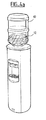
図1及び図2に示されているように、本発明の実施例によれば、ボトル10は、例えば透明なプラスティック材料のような多少なりとも剛性の材料でできており、独立型の貯水器、すなわちパイプラインに接続されていないものにおいて、水の配給を行うために用いられる。また、エラストマー材料からなるライナー12に、配給用の水を入れることで、水の清浄度が保証される。なお、ライナー12は、使用前(図1)は、ボトル10と比較して著しく小さな容量となっている。
As shown in FIGS. 1 and 2, according to an embodiment of the present invention, the
例えば、図1に示されているように、使用前は、ライナー12の長さは、ボトル10の高さの約半分であり、その径は、ボトルのネック部14よりもはるかに小さくなっている(図2)。一般的に、拡張可能あるいは伸縮可能なライナーの径及び長さは、飲料の粘性によって決定される。
水を入れた後は、ライナー12は、ボトルの内壁の形状と一致する。
本実施例においては、ライナー12は、ネック部14にオーバーラップするエッジ部16によって形成される開口を有している(図1及び図3)。
ライナー12がボトル10の内壁に圧力を加える(図2)ようにするためには、ライナー12に水を入れている間に、ボトル10内の空気を排出する必要がある。このため、本実施例においては、ボトル10は、任意の箇所に、少なくとも一つの穴(不図示)を備える。
水を入れた後は、ボトルは従来型のキャップ20(図3)で密封する。
この従来型キャップ20は、ネック部の上部24でロックされることにより保持されるスカート部22を備える。また、ネック部の上部24の外壁はライナー12のエッジ部16によってカバーされる。
For example, as shown in FIG. 1, before use, the length of the
After the water is added, the
In this embodiment, the
In order for the
After filling with water, the bottle is sealed with a conventional cap 20 (FIG. 3).
The
キャップ20は、シリンドリカル部28によって囲まれる中央開口部26を備え、このシリンドリカル部28はボトルの内部に入り込んでいる。また、シリンドルカル部の内側端部はエッジ部32及び34からなる内部キャップ30によって密封されている。エッジ部32はシリンドリカル部28の内壁に圧力を加え、一方、エッジ部34はシリンドリカル部28の外壁に圧力を加える。内部キャップ30は、シリンドリカル部28の外部フランジ36にエッジ部34をロックすることによって、シリンドリカル部28の端部に維持されている。
The
中央開口部26は、プラグ40によって密封されている。プラグ40をキャップ20の外壁に押し付ける接着材として、プラグ40がいったん離されると、再び接着することができないようなものが選択される。したがって、プラグ40のないボトルは、ボトルの内側に対する不当なアクセスを防止するためのプラグを備えていないため、使用できない。
また、公知の方法によれば、開口部26、シリンドリカル部28及びキャップ30は、貯水器の配水チューブ42とかみ合うように設計されている。したがって、ボトルが貯水器に装着されると、ネック部は下に向けられ(図1、2、及び3に示されているのと反対の方向)、配水チューブ42が開口部26を貫通する。このとき、ボトルに入るチューブ42の端部は閉じられている。これが、内部キャップ30を押すと、原則として、図3の破線によって示されるように、チューブ42の端部に固定された状態となる。ボトル内部では、チューブ42は、開口部44を有しており、ここからボトルの水が排出される。チューブ42は外部タップ(不図示)に接続されている。
The
Further, according to a known method, the
ボトルが貯水器から取り外されると、キャップ30は、原則として、シリンドリカル部28の端部の元の位置に戻り、貯水器から取り外された後のボトルの密閉性を保証する。
次いで、ボトルは洗浄、注入センターへ送られる。このセンターにおいて、キャップ20及びライナー12は廃棄され、ボトルは洗浄され、そして、新しいライナー12及び新しいキャップが装着される。新しいライナー12及び新しいキャップの装着を、注入の前に行うか後に行うかは、実施の態様によるが、これにより容器の清浄度が保証される
これにより、ライナー12付きボトル10を備えた貯水器において、使い捨てボトルによって配給される水と同じ衛生状態が保証される。
When the bottle is removed from the water reservoir, the
The bottle is then sent to a washing and filling center. At this center, the
図4及び4aは、本発明に係るボトル10及び内部ライナー12を装着した貯水器50を示している。図4においては、ライナー12は満タンであるが、図4aにおいては、水はボトル10の容量の4分の1以下になっている。水を配給している間、ライナーはフレキシブルであり、元の低容量の状態に戻ろうとするため、外部の空気が液体内を上昇することがない。したがって、水が外の空気と接触することがなく、これがさらにボトル内の液体の品質を保証することになる。
4 and 4a show a
ライナー12内の水は、重力によって、配給される。しかしながら、ライナー12が弾性材料でできている場合には、弾性がわずかに圧力を発揮し、水の配給を確実にする。
したがって、本発明によれば、標準的なボトルとキャップを使用しつづけることが可能であり、配水用の貯水器を改良することなく、水の汚染のリスクを大幅に低減することができる。実際に、注入に際して、洗浄後のボトルに残っているかもしれない残留物が汚染をもたらすことがなく、また、貯水器周囲の空気が水を通過することもない。
The water in the
Therefore, according to the present invention, it is possible to continue to use standard bottles and caps, and the risk of water contamination can be greatly reduced without improving the water storage reservoir. In fact, at the time of filling, the residue that may remain in the bottle after washing does not cause contamination and the air around the reservoir does not pass through the water.
ライナー12の存在により、注入に際して、配水用タンクのリスクを低減することができる。実際に、標準的な注入方法によれば、満タンのボトルから過剰な水が戻り、配水用タンクに戻ってしまう。したがって、使い捨てのライナーを使用することができない現行のシステムによれば、汚染されたボトルが配水用タンク全体を汚染してしまう可能性がある。
Due to the presence of the
上述してきた本発明の実施例において、標準的な貯水器に施される改良点は、実施の態様にもよるが、ボトルに穴を開けることと、低価格の、フレキシブルなライナーを設けることのみである。
図5に示されるような本発明の別実施例によれば、ライナー60は、ボトル(図5においては不図示)を密封するように設計されたキャップ62と一体となっている。
このキャップ62は、中央開口部66を備えた上部壁64からなり、この中央開口部66は、ライナー60の内側に向かって突出するシリンドリカル壁68によって囲まれている。キャップ62にはまた、図3に示される実施例のエッジ部22と同様の外側エッジ70があり、ボトルのネック部の最上部にロックされるよう設計されている。
In the embodiments of the present invention described above, the improvements made to a standard reservoir are only depending on the embodiment, but only the opening of the bottle and the provision of a low-cost, flexible liner. It is.
According to another embodiment of the invention as shown in FIG. 5, the
The cap 62 includes an
ライナー60の開口部の端部は、例えば密封あるいは熱による密封によって、シリンドリカル壁68と外部エッジ70との間で、壁64の内面と一体となっている。
中央キャップ72は、ライナー60に注入をした後で、中央開口部66を密封するよう設計されている。キャップ62はボトルのネックに装着される。
The end of the opening of the
The
上部壁64は、少なくとも一つの空気排出口74を有しており、外周部とライナー60の間に配置する。この空気排出口74により、ライナー60が満たされたときに、ライナー60とボトルの内壁との間の空気を排出することができる。また、この空気排出口74により、ライナー60が使用にあたり空になっていく際、すなわち貯水器に装着されている際に、空気をライナー60の外側でボトルの内部に戻すことができる。
The
図6は、図5に示されている実施例の変型例である。この実施例においては、ライナー60の上端部がシリンドリカル壁68と一体となっている。中央キャップ72は、ロックによって、シリンドリカル壁68とかみ合うように設計されたシリンドリカルエッジ76を備えている。また、この実施例においては、中央キャップ72のエッジ76は、壁68の内面のリブ82とかみ合うように設計された溝80を備えている。
中央キャップ72は、貯水器の配水用チューブ(図3に関連して記載されている)を通すことができるように設計されたシリンドリカル部86によって囲まれる中央開口部84を備えている。シリンドリカル部86は、図3で示されているキャップ30と同様の内部キャップ88によって密封される。
FIG. 6 is a modification of the embodiment shown in FIG. In this embodiment, the upper end portion of the
The
このキャップ88は、キャップ30と同様、ボトルが貯水器に装着されるときに、シリンドリカル部86から分離され、また、ボトルが貯水器から取り外されるときに、再びシリンドリカル部86を密封する。しかしながら、ボトルを貯水器から取り外す作業を行う間に、キャップ88が(図3のキャップ30と同様)、シリンドリカル部86を密封せずに、廃棄されることになるライナー60に残ることも起こり得る。しかしながら、ライナー60は廃棄されるため、このような作業中の欠陥は問題とはならない。
This
本発明の別実施例が図7及び8に記載されている。この実施例によれば、図3に関連して記載されているキャップ20のような標準的なタイプのボトルキャップを、注入の間に空気を排出するため、かつ水の配給中に空気を導入するための穴をボトルに開けることなく、使用することが可能である。
このため、ライナー90(図7)はカラー92と一体となっており、カラー92の下部面はボトル96の上端部94の上に載るように設計されている。また、カラー92の下部面は、少なくとも一つの溝98を備えており、この溝98は、ライナー90とボトル内壁との間では、ボトルの内部100に通じており、他方ではボトルの外部に通じている。
Another embodiment of the present invention is described in FIGS. According to this embodiment, a standard type of bottle cap, such as the
For this reason, the liner 90 (FIG. 7) is integrated with the
図8の実施例では、複数の溝981、982…が設けられている。
密封キャップは、ライナー90に水を注入する間は、装着されない。対照的に、図3に関連して記載されているように、キャップ(図7では不図示)は、水の配給中は装着されている。このキャップは、ライナー90とボトルの間の空間に空気が侵入することを、部分的に防止する。しかしながら、完全な気密性を保証するものではなく、ライナー90とボトル96との間に空気が侵入することを許すものであるが、この空気の流入は、注入の間ほどは重要ではない。なお、このような空気の流入に関する差異は、水の配給が水の注入よりはるかにゆっくりと行われるため、問題とならないものである。
In the embodiment of FIG. 8, a plurality of
The sealing cap is not attached while water is injected into the
溝98の数又は区切りを少なくするため、カラー92をボトル96のエッジ部94から分離させて、ライナー90を水で満たすようにしてもよい。このような状況下で、ライナー90の外側であってボトル内部にある空気は、水の注入中に、エッジ部94とカラー92の間の空間を通り抜けることができる。
変型例として、水を貯水器に配給することを容易にするため、ボトル内のライナーに過剰圧力をかけることも可能である。
In order to reduce the number or separation of the
As a variant, it is possible to apply excess pressure to the liner in the bottle in order to facilitate the distribution of water to the reservoir.
別実施例が図9、10及び11に示されている。この実施例においては、キャップ110は、内部に向かって、スリーブ112を備えており、例えば、図6に示されているスリーブ68と同様のものが考えられる。スリーブ112は、その下部端に溝114を備えており、ライナー116はこの溝114とダブル成形(duplicate molding)によって一体となっている。
このため、キャップは、例えばポリエチレン又はポリプロピレンから作製されており、溝114は、その底部に穴1181、1182を規則的な間隔で備え、そのエッジ部にこちらもまた規則的な間隔で吐出穴1201…を備えている。
Another embodiment is shown in FIGS. In this embodiment, the
For this reason, the cap is made of, for example, polyethylene or polypropylene, and the
次いで、この溝は、溶融ラテックス浴に浸漬され、ライナー116が作られて、図11に示されるように、溝にはんだ付けされ成形される。
本実施例の場合、キャップとライナーは廃棄できるものである。
The groove is then immersed in a molten latex bath and a
In this embodiment, the cap and liner can be discarded.
また別の実施例が図12、13及び14に示されている。この実施例においては、キャップ122は周辺部122及び中央部134からなる。さらに、周辺部122はスリーブ124と溝126を備えており、溝126はライナー130のロールエッジ128を受けるようになっている。
ロールエッジ128は、カラー132により溝126の底部に維持されている。このカラー132は、外スリーブ138を備える中央部134とかみ合うものである。すなわち、端部140は、スリーブ138の突起144を周辺部122の溝146に合わせることでキャップの中央部134が周辺部122と結合したとき、カラー132をロールエッジ128に対して支持し、溝126の底部に押し付ける。
Yet another embodiment is shown in FIGS. In this embodiment, the
本実施例では、スリーブ124の端部の径は、スリーブのその他の部分の径よりも大きくなっており、その結果、カラー132の上方ストッパとなるエッジ150を形成している。
In the present embodiment, the diameter of the end portion of the
図12に示されるように、本実施例では、キャップの中央部134は、図6のスリーブ86と同様、中央スリーブ152を備え、その下端は、図6のキャップ88と同様の役割を果たす面取り部154を備えている。すなわち、面取り部154は、ボトルが貯水器から取り外されたときに、液体の漏洩を防止あるいは制限する役割を果たすものである。
面取り部154は、チューブ42(図3)がボトル内部に入ることを可能にするため、カット部あるいはプレカット部を備えている。図13に示される実施例においては、プレカット部は放射状の形状であり、すなわち、カット部156はキャップの軸160に対応する中央部158に集まっている。
As shown in FIG. 12, in this embodiment, the
The chamfered
図14に示される実施例においては、面取り部154はスパイラル160にカットされている。
In the embodiment shown in FIG. 14, the chamfered
図15に示される実施例は、以下の点で図12に示される実施例と異なっている。すなわち、主キャップ170の中央部が大径の上部172を有しており、そこには中央キャップ174がキャッチ部176によって入り込んでいる。また、この大径の上部172は下方に伸びて、小径のシリンドリカル壁178へと通じており、このシリンドリカル壁178は、ショルダー180を介して上部172に接続している。ショルダー180は中央キャップ174の下端182を支持する。
シリンドリカル壁178は、内側に折り返すエッジ部184を終点とし、そこにライナー190がはんだ付けされている。
The embodiment shown in FIG. 15 differs from the embodiment shown in FIG. 12 in the following points. That is, the central portion of the
The
図16に示される実施例は、壁178が下端のエッジ部を有していないという点で、図15に示される実施例と異なっている。この実施例では、ライナー192は壁178の下部194にはんだ付けされている。
The embodiment shown in FIG. 16 differs from the embodiment shown in FIG. 15 in that the
これらの実施例においては、ライナーの材料はフレキシブルかつ膨張可能なものでもよく、フレキシブルかつ膨張不能なものでもよい。
概して、すべての実施例において、ライナーのフレキシブルな性質のため、液体の配給中に空気が液体の中に入り込むことが防止される。これは、空になったライナーの上部が重力によって沈下し、空気が戻る余地が実質的に残されないからである。言い換えれば、ライナーの上部は折りたたまれて、残りの液体の自由表面と実質的に接触しつづける。なお、弾性的なライナーの場合には、折りたたみ箇所が少なくなる。
In these embodiments, the liner material may be flexible and expandable, or may be flexible and non-expandable.
In general, in all embodiments, the flexible nature of the liner prevents air from entering the liquid during liquid delivery. This is because the top of the emptied liner sinks due to gravity, leaving virtually no room for air to return. In other words, the top of the liner is folded and remains in substantial contact with the remaining liquid free surface. In the case of an elastic liner, the number of folding points is reduced.
Claims (23)
The collar (92) is integral with the opening of the liner (90) and has at least one channel (98) that brings the space (100) inside the bottle and outside the liner into contact with the atmosphere. The member according to claim 10.
Applications Claiming Priority (3)
| Application Number | Priority Date | Filing Date | Title |
|---|---|---|---|
| FR0202354A FR2837183A1 (en) | 2002-02-25 | 2002-02-25 | Method for filling water carboy comprises introducing water into flexible liner, introduced in carboy, having rim which overlaps carboy opening |
| FR0209898A FR2837184B1 (en) | 2002-02-25 | 2002-08-02 | ACCESSORIES FOR CONTAINERS OF FOOD LIQUIDS ESPECIALLY WATER |
| PCT/FR2003/000590 WO2003072457A2 (en) | 2002-02-25 | 2003-02-24 | Fittings for liquid foodstuff, particularly water, containers |
Publications (1)
| Publication Number | Publication Date |
|---|---|
| JP2005518317A true JP2005518317A (en) | 2005-06-23 |
Family
ID=27767075
Family Applications (1)
| Application Number | Title | Priority Date | Filing Date |
|---|---|---|---|
| JP2003571173A Pending JP2005518317A (en) | 2002-02-25 | 2003-02-24 | Fitting member used in containers for liquid beverages such as water |
Country Status (11)
| Country | Link |
|---|---|
| US (1) | US20050155664A1 (en) |
| EP (1) | EP1480896B1 (en) |
| JP (1) | JP2005518317A (en) |
| CN (1) | CN1639027A (en) |
| AT (1) | ATE350304T1 (en) |
| AU (1) | AU2003224218A1 (en) |
| DE (1) | DE60310888T2 (en) |
| ES (1) | ES2280744T3 (en) |
| FR (1) | FR2837184B1 (en) |
| MX (1) | MXPA04008192A (en) |
| WO (1) | WO2003072457A2 (en) |
Cited By (4)
| Publication number | Priority date | Publication date | Assignee | Title |
|---|---|---|---|---|
| JP2008007181A (en) * | 2006-06-30 | 2008-01-17 | Cosmo Life:Kk | Cartridge container for drink dispenser |
| JP2010132310A (en) * | 2008-12-04 | 2010-06-17 | Fujiyama Corp | Drinking water storing tool for server |
| KR20190054163A (en) * | 2016-09-29 | 2019-05-21 | 오카도 이노베이션 리미티드 | Robotic processing system and method |
| JP2020083406A (en) * | 2018-11-28 | 2020-06-04 | 株式会社フェイスアップ | Bottle cap |
Families Citing this family (4)
| Publication number | Priority date | Publication date | Assignee | Title |
|---|---|---|---|---|
| NL1024142C2 (en) * | 2003-08-20 | 2005-02-22 | E H Klijn Beheer B V | Holder for dye to be mixed. |
| FR2860215B1 (en) * | 2003-09-26 | 2006-08-18 | Logiplast | CONTAINER FOR CONTAINING FOOD LIQUID |
| US20080173648A1 (en) * | 2007-01-23 | 2008-07-24 | Escobar Juan C | Trash receptacle with bag retention system |
| CN106562553A (en) * | 2016-10-12 | 2017-04-19 | 福州汇智集佳电子技术有限公司 | Water-drinking water bag |
Family Cites Families (5)
| Publication number | Priority date | Publication date | Assignee | Title |
|---|---|---|---|---|
| FR1124356A (en) * | 1954-05-22 | 1956-10-09 | Device for taking and storing body fluids, such as blood, serums, injection solutions and similar fluids | |
| FR2094286A5 (en) * | 1970-06-16 | 1972-02-04 | Eluere Yves | |
| US4875508A (en) * | 1985-06-22 | 1989-10-24 | The Coca-Cola Company | Beverage container suitable for use in outer space |
| DE8705463U1 (en) * | 1987-04-13 | 1987-06-04 | Schoellhammer Lutz | Interchangeable flexible inner casing for containers |
| US5301838A (en) * | 1991-01-23 | 1994-04-12 | Continental Pet Technologies, Inc. | Multilayer bottle with separable inner layer and method for forming same |
-
2002
- 2002-08-02 FR FR0209898A patent/FR2837184B1/en not_active Expired - Fee Related
-
2003
- 2003-02-24 ES ES03720639T patent/ES2280744T3/en not_active Expired - Lifetime
- 2003-02-24 CN CN03804479.XA patent/CN1639027A/en active Pending
- 2003-02-24 AU AU2003224218A patent/AU2003224218A1/en not_active Abandoned
- 2003-02-24 AT AT03720639T patent/ATE350304T1/en not_active IP Right Cessation
- 2003-02-24 DE DE60310888T patent/DE60310888T2/en not_active Expired - Fee Related
- 2003-02-24 MX MXPA04008192A patent/MXPA04008192A/en unknown
- 2003-02-24 JP JP2003571173A patent/JP2005518317A/en active Pending
- 2003-02-24 US US10/505,507 patent/US20050155664A1/en not_active Abandoned
- 2003-02-24 WO PCT/FR2003/000590 patent/WO2003072457A2/en active IP Right Grant
- 2003-02-24 EP EP03720639A patent/EP1480896B1/en not_active Expired - Lifetime
Cited By (9)
| Publication number | Priority date | Publication date | Assignee | Title |
|---|---|---|---|---|
| JP2008007181A (en) * | 2006-06-30 | 2008-01-17 | Cosmo Life:Kk | Cartridge container for drink dispenser |
| JP4664870B2 (en) * | 2006-06-30 | 2011-04-06 | 株式会社コスモライフ | Cartridge container for beverage dispenser |
| JP2010132310A (en) * | 2008-12-04 | 2010-06-17 | Fujiyama Corp | Drinking water storing tool for server |
| KR20190054163A (en) * | 2016-09-29 | 2019-05-21 | 오카도 이노베이션 리미티드 | Robotic processing system and method |
| JP2020500503A (en) * | 2016-09-29 | 2020-01-16 | オカド・イノベーション・リミテッド | Robot processing system and equipment |
| JP7019682B2 (en) | 2016-09-29 | 2022-02-15 | オカド・イノベーション・リミテッド | Robot processing systems and equipment |
| KR102422567B1 (en) * | 2016-09-29 | 2022-07-18 | 오카도 이노베이션 리미티드 | Robotic Handling Systems and Methods |
| JP2020083406A (en) * | 2018-11-28 | 2020-06-04 | 株式会社フェイスアップ | Bottle cap |
| JP7164111B2 (en) | 2018-11-28 | 2022-11-01 | 株式会社フェイスアップ | bottle cap |
Also Published As
| Publication number | Publication date |
|---|---|
| CN1639027A (en) | 2005-07-13 |
| DE60310888D1 (en) | 2007-02-15 |
| AU2003224218A1 (en) | 2003-09-09 |
| WO2003072457A3 (en) | 2004-03-04 |
| EP1480896A2 (en) | 2004-12-01 |
| AU2003224218A8 (en) | 2003-09-09 |
| MXPA04008192A (en) | 2005-08-16 |
| US20050155664A1 (en) | 2005-07-21 |
| EP1480896B1 (en) | 2007-01-03 |
| DE60310888T2 (en) | 2008-02-14 |
| FR2837184B1 (en) | 2004-09-03 |
| ATE350304T1 (en) | 2007-01-15 |
| FR2837184A1 (en) | 2003-09-19 |
| ES2280744T3 (en) | 2007-09-16 |
| WO2003072457A2 (en) | 2003-09-04 |
Similar Documents
| Publication | Publication Date | Title |
|---|---|---|
| US4699188A (en) | Hygienic liquid dispensing system | |
| RU2605177C2 (en) | Vessel corking device containing means of additive introduction into vessel contents | |
| US6874656B2 (en) | Vented closure | |
| JP5105553B2 (en) | Container closure having means for introducing additives into the contents of the container | |
| US8056766B2 (en) | Assembly for containing and dispensing a liquid | |
| US8025183B2 (en) | Pour spout | |
| JP5321984B2 (en) | Closure for beverage containers and method for closing an opening of a container | |
| WO1999008929A1 (en) | Filler adapter for a multi-chambered container | |
| WO1985000340A1 (en) | Sterilizable container with inner closure and collapse-resistant cover | |
| RU2507123C2 (en) | Device to couple drink vessel with fitting | |
| US5842076A (en) | Apparatus for supplying a liquid from a container | |
| JP2005518317A (en) | Fitting member used in containers for liquid beverages such as water | |
| JP2011152948A (en) | Replacement container for pump | |
| US5918779A (en) | Value assembly for supplying pressurized liquid from a container | |
| JP4954695B2 (en) | Refill container | |
| JP3989365B2 (en) | Inner bag for containers. | |
| US11332277B2 (en) | Apparatus and method for separation of air from fluids | |
| US20190168950A1 (en) | Gravity-oriented one-way valve container apparatus and method | |
| JP2002326605A (en) | Liquid-filling method for delaminating bottle, and repacking container which is used for the same method | |
| JPH10167309A (en) | Composite cap | |
| JP5415342B2 (en) | Refill receptacle for refill | |
| JP3874953B2 (en) | Container with replacement bottle | |
| US650413A (en) | Siphon-bottle. | |
| JPH10157758A (en) | Pouring mouth plug | |
| KR102069710B1 (en) | Container filling apparatus that prevents the bubble |
Legal Events
| Date | Code | Title | Description |
|---|---|---|---|
| A621 | Written request for application examination |
Free format text: JAPANESE INTERMEDIATE CODE: A621 Effective date: 20060221 |
|
| A131 | Notification of reasons for refusal |
Free format text: JAPANESE INTERMEDIATE CODE: A131 Effective date: 20090113 |
|
| A02 | Decision of refusal |
Free format text: JAPANESE INTERMEDIATE CODE: A02 Effective date: 20090721 |