RU2507123C2 - Device to couple drink vessel with fitting - Google Patents
Device to couple drink vessel with fitting Download PDFInfo
- Publication number
- RU2507123C2 RU2507123C2 RU2011137701/12A RU2011137701A RU2507123C2 RU 2507123 C2 RU2507123 C2 RU 2507123C2 RU 2011137701/12 A RU2011137701/12 A RU 2011137701/12A RU 2011137701 A RU2011137701 A RU 2011137701A RU 2507123 C2 RU2507123 C2 RU 2507123C2
- Authority
- RU
- Russia
- Prior art keywords
- fitting
- cylinder
- connecting means
- adapter ring
- locking protrusion
- Prior art date
Links
Images
Classifications
-
- B—PERFORMING OPERATIONS; TRANSPORTING
- B67—OPENING, CLOSING OR CLEANING BOTTLES, JARS OR SIMILAR CONTAINERS; LIQUID HANDLING
- B67D—DISPENSING, DELIVERING OR TRANSFERRING LIQUIDS, NOT OTHERWISE PROVIDED FOR
- B67D1/00—Apparatus or devices for dispensing beverages on draught
- B67D1/08—Details
- B67D1/0829—Keg connection means
-
- B—PERFORMING OPERATIONS; TRANSPORTING
- B67—OPENING, CLOSING OR CLEANING BOTTLES, JARS OR SIMILAR CONTAINERS; LIQUID HANDLING
- B67D—DISPENSING, DELIVERING OR TRANSFERRING LIQUIDS, NOT OTHERWISE PROVIDED FOR
- B67D1/00—Apparatus or devices for dispensing beverages on draught
- B67D1/04—Apparatus utilising compressed air or other gas acting directly or indirectly on beverages in storage containers
- B67D1/0412—Apparatus utilising compressed air or other gas acting directly or indirectly on beverages in storage containers the whole dispensing unit being fixed to the container
Abstract
Description
Изобретение относится к устройству для соединения емкости для приема жидкостей в виде напитков, таких как пиво, безалкогольные напитки и вино, с фитингом, причем емкость содержит баллон, который сверху, на своем головном конце, выполнен с буртикообразным присоединительным средством, которое для заполнения жидкостью соединяется с фитингом, имеющим закрываемые отверстия для сжатого газа, с одной стороны, и для жидкости, с другой.The invention relates to a device for connecting a container for receiving liquids in the form of drinks, such as beer, soft drinks and wine, with a fitting, the container containing a cylinder, which is on top, at its head end, made with a shoulder-like connecting means, which connects to fill with liquid with a fitting having lockable openings for compressed gas, on the one hand, and for liquids, on the other.
Выполненные таким образом емкости, или баллоны, в частности, изготовленные из полиэтилентерефталата, для приема напитков часто снабжаются заправленными в них мешками или тому подобными оболочками. Последние расправляются при заполнении и препятствуют попаданию в напиток воздуха или диоксида углерода.Tanks made in this way, or cylinders, in particular made of polyethylene terephthalate, are often supplied with bags filled with bags or the like for receiving drinks. The latter straightens out during filling and prevents air or carbon dioxide from entering the drink.
Такие емкости, или баллоны, предпочтительно, используются в устройствах для реализуемого с помощью сжатого углекислого газа отпуска в разлив напитков, таких как пиво, безалкогольные напитки и вино, выдерживаемых при температуре для питья. При срабатывании разливного рычага напиток через нагнетательную трубку, заходящую внутрь баллона или во внутренний мешок, вытесняется в направлении выпускного отверстия для напитка.Such containers, or cylinders, are preferably used in devices for dispensing bottled drinks, such as beer, soft drinks and wine, at a temperature for drinking, using compressed carbon dioxide. When the filling lever is activated, the beverage is displaced through the discharge tube entering the container or into the inner bag in the direction of the outlet for the beverage.
Такое устройство для отпуска напитков в разлив известно, например, из ЕР 1293476 B1. Напиток может отбираться, или баллон может наполняться через разливную головку, или присоединительный элемент, надвигаемые на установленный сверху на емкости, или на баллоне, предохранительный фитинг, содержащий клапан для подачи напитка и газовый клапан.Such a device for dispensing drinks on tap is known, for example, from EP 1293476 B1. The beverage may be withdrawn, or the cylinder may be filled through the tapping head, or a connecting element pushed onto a safety fitting mounted on top of the container, or on the cylinder, comprising a beverage valve and a gas valve.
Из DE 102005025561 A1 известен затвор для емкости с напитком, выполненный для отбора жидкости, содержащий корпус затвора с цилиндрической внутренней частью, в которой установлен регулирующий элемент клапана. Корпус затвора имеет цилиндрическую наружную втулку с внутренней резьбой, с помощью которой наружная втулка навинчивается на наружную резьбу патрубка емкости.From DE 102005025561 A1 there is known a closure for a beverage container made for liquid withdrawal, comprising a closure body with a cylindrical inner part in which a valve control element is installed. The shutter body has a cylindrical outer sleeve with an internal thread, with which the outer sleeve is screwed onto the external thread of the tank nozzle.
Кроме того, из уровня техники известно, что предохранительный фитинг, содержащий разливную головку, при установке в верхней части емкости спрессовывается со стенкой емкости, вследствие чего возникает неразъемное соединение. Эти так называемые одноразовые резьбы после отбора напитка выбрасываются вместе с запрессованным предохранительным фитингом.In addition, it is known from the prior art that a safety fitting comprising a tapping head, when installed in the upper part of the tank, is pressed against the wall of the tank, as a result of which an integral connection occurs. These so-called disposable threads are thrown away after the beverage is taken together with the pressed-in safety fitting.
В основу изобретения положена задача создания для подобной емкости возможности надежного и просто заменяемого соединения с фитингом, или предохранительным фитингом.The basis of the invention is the task of creating for such a capacity the possibility of a reliable and easily replaceable connection with a fitting or a safety fitting.
Эта задача согласно изобретению решается с помощью соединяющего присоединительное средство баллона с фиксирующим пазом фитинга снаружи адаптерного кольца, которое согласно предпочтительному варианту выполнения изобретения сразу же выполняется на присоединительном средстве и представляет собой тем самым интегрированный составной элемент баллона, который нельзя легко утерять. В это кольцо фитинг достаточно вставить лишь настолько, чтобы фиксирующий выступ адаптерного кольца вошел в зацепление с фиксирующим пазом фитинга. Такое адаптерное кольцо позволяет использовать обычный одноразовый фитинг также и для баллона из полиэтилентерефталата.This task according to the invention is accomplished by connecting the connecting means of the cylinder to the fixing groove of the fitting on the outside of the adapter ring, which according to the preferred embodiment of the invention is immediately carried out on the connecting means and thus constitutes an integrated component of the cylinder, which cannot be easily lost. It is enough to insert the fitting into this ring only so that the locking protrusion of the adapter ring engages with the fixing groove of the fitting. Such an adapter ring allows the use of a conventional disposable fitting also for a polyethylene terephthalate cylinder.
Другой вариант выполнения изобретения предусматривает цельное адаптерное кольцо, фиксируемое в пазу фитинга, а также буртикообразным присоединительным средством баллона. Отдельное адаптерное кольцо, изготовленное из пластмассы, перед соединением фитинга с баллоном надвигается на фитинг снизу. После того как фитинг с промежуточным включением радиального уплотнения будет надет на выступ с гладкой поверхностью, проходящий внутри буртикообразного присоединительного средства баллона, адаптерное кольцо на фитинге сдвигается в вертикальном направлении вниз настолько, чтобы, с одной стороны, его верхний присоединительный конец фиксировался в окружном пазу фитинга, а, с другой стороны, его нижний присоединительный конец фиксировался буртикообразным, или кольцеобразно выступающим, присоединительным средством баллона.Another embodiment of the invention provides a one-piece adapter ring, fixed in the groove of the fitting, as well as a shoulder-shaped connecting means of the cylinder. A separate adapter ring, made of plastic, is pushed onto the fitting from below before connecting the fitting to the bottle. After the fitting with the intermediate engagement of the radial seal is worn on a ledge with a smooth surface extending inside the collar-like connecting means of the cylinder, the adapter ring on the fitting is moved vertically downwards so that, on the one hand, its upper connecting end is fixed in the circumferential groove of the fitting , and, on the other hand, its lower connecting end was fixed flange-like, or annularly protruding, connecting means of the cylinder.
Для введения адаптерного кольца в зацепление с фитингом и баллоном согласно изобретению предлагается, чтобы верхний и нижний присоединительные концы адаптерного кольца были выполнены с фиксирующими выступами, из которых верхний фиксирующий выступ входит в зацепление с пазом фитинга, а нижний фиксирующий выступ зацепляет буртикообразное присоединительное средство. Как верхний, так и нижний фиксирующие выступы выполнены цельными и проходят, соответственно, по внутренней периферии верхнего и нижнего присоединительных концов адаптерного кольца. Верхний присоединительный конец, подогнанный к наружному диаметру фитинга, имеет по сравнению с нижним присоединительным концом, подогнанным к наружному диаметру буртикообразного присоединительного средства, меньший диаметр, так что при переходе адаптера между верхним и нижним присоединительными концами получается наклонная поверхность, сужающаяся в направлении вверх. Эта наклонная поверхность, или ступенька, адаптера после фиксации фитингом и баллоном располагается с предварительным натяжением заподлицо с комплементарным ей внешним контуром буртикообразного присоединительного средства, выполненного в виде выступа, благодаря чему достигается стабилизация адаптерного кольца.In order to engage the adapter ring with the fitting and cylinder according to the invention, it is proposed that the upper and lower connecting ends of the adapter ring are made with locking protrusions, of which the upper locking protrusion engages with the groove of the fitting and the lower locking protrusion engages a shoulder-shaped connecting means. Both the upper and lower locking protrusions are made integral and extend, respectively, along the inner periphery of the upper and lower connecting ends of the adapter ring. The upper connecting end fitted to the outer diameter of the fitting has a smaller diameter compared to the lower connecting end fitted to the outer diameter of the collar-shaped connecting means, so that when the adapter passes between the upper and lower connecting ends, an inclined surface tapers upward. After fixing the fitting and the cylinder, this inclined surface, or step, of the adapter is pre-tensioned flush with the external contour of the shoulder-shaped connecting means complementary to it, made in the form of a protrusion, thereby stabilizing the adapter ring.
Один из предпочтительных вариантов выполнения изобретения предусматривает, чтобы присоединительные концы были соединены со средней частью адаптерного кольца радиально пружинящим образом. Благодаря этому присоединительные концы в процессе соединения, с одной стороны, на фитинге, а, с другой, на наклонном внешнем контуре буртикообразного присоединительного средства расширяются кнаружи за пределы внутри расположенных верхних и нижних фиксирующих выступов. Как только верхний фиксирующий выступ совместится с окружным пазом в фитинге, а нижний фиксирующий выступ минует буртикообразное присоединительное средство, присоединительные концы отпружинивают или заскакивают обратно в свое исходное положение, причем верхний фиксирующий выступ надежно и прочно заскакивает в паз фитинга, а нижний фиксирующий выступ с геометрическим замыканием зацепляет буртикообразное присоединительное средство.One of the preferred embodiments of the invention provides that the connecting ends are connected to the middle part of the adapter ring in a radially spring manner. Due to this, the connecting ends in the connection process, on the one hand, on the fitting, and, on the other hand, on the inclined external contour of the shoulder-shaped connecting means, expand outwardly outside the inside of the upper and lower fixing protrusions. As soon as the upper locking protrusion is aligned with the circumferential groove in the fitting and the lower locking protrusion passes the collar-like connecting means, the connecting ends spring back or spring back to their original position, the upper locking protrusion reliably and firmly pops into the groove of the fitting, and the lower locking protrusion with a geometric closes the shoulder-shaped connecting means.
Другой предпочтительный вариант выполнения изобретения предусматривает, чтобы верхний фиксирующий выступ был выполнен с вводным скосом, сужающимся книзу. Последний центрирует фитинг и облегчает надвигание адаптерного кольца. Кроме того, выполненное таким образом фиксирующее кольцо лишь с небольшой опорной поверхностью скользит по фитингу, к тому же обеспечивается содействие захождению верхнего фиксирующего выступа в паз фитинга.Another preferred embodiment of the invention provides for the upper locking protrusion to be made with an opening bevel tapering downward. The latter centers the fitting and facilitates the sliding of the adapter ring. In addition, the locking ring made in this way, with only a small supporting surface, slides along the fitting, in addition, the upper locking protrusion is inserted into the groove of the fitting.
Нижний фиксирующий выступ согласно изобретению, напротив, выполнен с набегающим скосом, сужающимся кверху. Последний при надевании нижнего присоединительного конца адаптерного кольца на буртикообразное присоединительное средство баллона обеспечивает центрированное простое скольжение вниз по внешнему контуру буртика в виде выступа. Кроме того, набегающий скос способствует радиальному разжиманию нижнего присоединительного конца при прохождении буртикообразного присоединительного средства.The lower locking protrusion according to the invention, in contrast, is made with a ramp which tapers upward. The latter, when putting the lower connecting end of the adapter ring onto the shoulder-shaped connecting means of the cylinder, provides centered simple sliding downward along the outer contour of the shoulder in the form of a protrusion. In addition, the ramp facilitates radial expansion of the lower connecting end while passing the shoulder-like connecting means.
Другие признаки и детали изобретения вытекают из формулы изобретения и последующего описания примеров выполнения изобретения, изображенных на фигурах, на которых:Other features and details of the invention follow from the claims and the following description of examples of carrying out the invention depicted in the figures in which:
фиг.1 изображает в продольном разрезе местный вид фитинга с буртикообразным присоединительным средством баллона-емкости, соединенного или зафиксированного надвинутым снаружи адаптерным кольцом, аfigure 1 depicts in longitudinal section a local view of the fitting with a shoulder-shaped connecting means of the tank container connected or fixed by the adapter ring pulled out from the outside, and
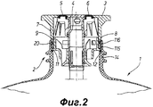
фиг.2 - тот же местный вид в продольном разрезе, причем адаптерное кольцо выполнено в качестве интегрированного составного элемента баллона-емкости сразу же на его буртикообразно м присоединительном средстве.figure 2 is the same local view in longitudinal section, and the adapter ring is made as an integrated component of the container tank immediately on its shoulder-shaped connecting means.
На фиг.1 в качестве емкости для приема и отпуска жидкостей в виде напитков, таких как пиво, безалкогольные напитки и вино, под действием сжатого газа изображен баллон 1, изготовленный из термопластичной пластмассы, в частности, из полиэтилентерефталата.Figure 1 as a container for receiving and dispensing liquids in the form of drinks, such as beer, soft drinks and wine, under the action of compressed gas shows a cylinder 1 made of thermoplastic plastic, in particular polyethylene terephthalate.
На верхней стороне баллон 1 выполнен с горлышком 2 баллона, на котором установлен предохранительный фитинг 3, имеющий фитинговую, или нагнетательную, трубку 4, заходящую в баллон 1, по которой поднимается жидкость. Кроме того, предохранительный фитинг 3 снабжен закрываемыми отверстиями 5, 6 для сжатого газа, с одной стороны, и для жидкости, с другой. К отверстиям для заполнения напитком, например, на пивном заводе, подсоединяются присоединительный элемент или разливная головка для разлива потребителем.On the upper side, the cylinder 1 is made with a
Предохранительный фитинг 3 содержит кольцеобразный наружный корпус 7, снабженный окружным пазом 8. Наружный корпус 7 снизу переходит в двустенный стационарный опорный элемент 9, между внутренней и наружной кольцевыми стенками 10а, 10b которого образованы проточные каналы, причем внутренняя кольцевая стенка 10а одновременно является направляющей для фитинговой трубки 4, устанавливаемой в примере выполнения в продольном направлении.The safety fitting 3 comprises an annular
Наружная кольцевая стенка 10b имеет окружной выступающий участок 11 поперечного ребра, который, с одной стороны, принимает кольцеобразный наружный корпус 7, а, с другой стороны, с промежуточным включением уплотнения 12 опирается на кольцевую поверхность 13, выполненную внутри горлышка 2 баллона.The outer annular wall 10b has a circumferential protruding section 11 of the transverse rib, which, on the one hand, receives an annular
По своей наружной окружности горлышко 2 баллона снабжено буртикообразным присоединительным средством 14, служащим в качестве ответного паза для присоединительного средства.In its outer circumference, the neck of the
Присоединительное средство выполнено в виде цельного адаптерного кольца 15, снабженного изнутри на своем верхнем присоединительном конце 15а и на своем нижнем присоединительном конце 15b фиксирующими выступами 16, 17, из которых верхний фиксирующий выступ 16 входит в зацепление с пазом 8 фитинга, а нижний фиксирующий выступ 17 зацепляет буртикообразное присоединительное средство 14.The connecting means is made in the form of a one-piece adapter ring 15 provided internally at its upper connecting end 15a and at its lower connecting end 15b with locking protrusions 16, 17, of which the upper locking protrusion 16 is engaged with the
Для соединения фитинга 3 с баллоном 1 с силовым и геометрическим замыканием адаптерное кольцо 15, выполненное из упругого материала, с помощью вводного скоса 20 верхнего присоединительного конца 15а надевается снизу на кольцеобразный наружный корпус 7 фитинга 3, причем верхний окружной фиксирующий выступ 16 радиально расширяется кнаружи и таким образом оказывается под предварительным напряжением. Затем фитинг 3 с опорным элементом 9 вставляется в горлышко 2 баллона, а адаптерное кольцо 15 смещается вниз. Вместе с тем нижний фиксирующий выступ 17 скользит по внешнему контуру в виде выступа буртикообразного присоединительного средства 14, вследствие чего он также радиально расширяется и оказывается под предварительным напряжением. При этом выполненный на фиксирующем выступе 17 набегающий скос 19, сужающийся в направлении вверх, облегчает соединение и радиальное разжимание.To connect the fitting 3 to the cylinder 1 with a power and geometric closure, the adapter ring 15, made of an elastic material, is inserted from below onto the annular
Как только верхний фиксирующий выступ 16 совместится с фиксирующим пазом 8, а фиксирующий выступ 17 полностью минует буртикообразное присоединительное средство 14, верхний фиксирующий выступ 16 с помощью вводного скоса 20 зафиксируется в пазу 8, а нижний фиксирующий выступ 17 зацепит буртикообразное присоединительное средство 14 с геометрическим замыканием.As soon as the upper locking protrusion 16 is combined with the
На фиг.2 изображен вариант выполнения, в котором адаптерное кольцо 115 сразу же выполнено на горлышке 2 баллона, т.е. на его концевом верхнем присоединительном средстве 14. Поскольку фиксация со стороны горлышка 2 баллона, или присоединительного средства 14, отпадает, пружинящее упругое адаптерное кольцо 115 в этом случае имеет только один снабженный вводным выступом 20 окружной фиксирующий выступ 116, который при надвигании фитинга 3 входит в зацепление с его фиксирующим пазом 8 и надежно соединяет баллон с фитингом 3. В остальном конструктивные элементы и принцип действия этого варианта выполнения идентичны таковым на фиг.1.Figure 2 shows an embodiment in which the
Перечень позицийList of items
1 баллон (емкость)1 cylinder (capacity)
2 горлышко/горлышко емкости2 neck / neck of capacity
3 фитинг (предохранительный фитинг)3 fitting (safety fitting)
4 фитинг/нагнетательная трубка4 fitting / discharge pipe
5 (проточное) отверстие5 (flow) hole
6 (проточное) отверстие6 (flow) hole
7 наружный корпус7 outer casing
8 паз (окружной паз)8 groove (circumferential groove)
9 опорный элемент9 support element
10a внутренняя кольцевая стенка10a inner annular wall
10b наружная кольцевая стенка10b outer ring wall
11 участок поперечного ребра11 section of the transverse rib
12 уплотнение12 seal
13 кольцевая поверхность13 ring surface
14 присоединительное средство (баллона)14 connecting means (cylinder)
15 адаптерное кольцо15 adapter ring
15a верхний присоединительный конец15a upper connecting end
15b нижний присоединительный конец15b lower connecting end
16 фиксирующий выступ (верхний)16 locking tab (upper)
17 фиксирующий выступ (нижний)17 locking protrusion (lower)
18 внешний контур18 external circuit
19 набегающий скос19 canting
20 вводный скос20 opening bevel
115 адаптерное кольцо115 adapter ring
116 фиксирующий выступ116 locking tab
Claims (7)
Applications Claiming Priority (3)
| Application Number | Priority Date | Filing Date | Title |
|---|---|---|---|
| DE202009002838U DE202009002838U1 (en) | 2009-02-14 | 2009-02-14 | Device for connecting a beverage container to a fitting |
| DE202009002838.0 | 2009-02-14 | ||
| PCT/EP2010/000374 WO2010091775A1 (en) | 2009-02-14 | 2010-01-22 | Device for connecting a beverage container to a fitting |
Publications (2)
| Publication Number | Publication Date |
|---|---|
| RU2011137701A RU2011137701A (en) | 2013-03-20 |
| RU2507123C2 true RU2507123C2 (en) | 2014-02-20 |
Family
ID=40691193
Family Applications (1)
| Application Number | Title | Priority Date | Filing Date |
|---|---|---|---|
| RU2011137701/12A RU2507123C2 (en) | 2009-02-14 | 2010-01-22 | Device to couple drink vessel with fitting |
Country Status (8)
| Country | Link |
|---|---|
| US (1) | US20110280502A1 (en) |
| EP (1) | EP2396270B1 (en) |
| DE (1) | DE202009002838U1 (en) |
| DK (1) | DK2396270T3 (en) |
| ES (1) | ES2471466T3 (en) |
| RU (1) | RU2507123C2 (en) |
| UA (1) | UA102588C2 (en) |
| WO (1) | WO2010091775A1 (en) |
Families Citing this family (8)
| Publication number | Priority date | Publication date | Assignee | Title |
|---|---|---|---|---|
| WO2012075972A1 (en) * | 2010-12-09 | 2012-06-14 | Dsi Getränkearmaturen Gmbh | Keg valve arrangement |
| DE102011015516A1 (en) | 2011-03-30 | 2012-10-04 | SCHäFER WERKE GMBH | Container for holding pressurized beverage liquids |
| DE102012007642B4 (en) * | 2012-04-18 | 2014-08-21 | Fass-Frisch Gmbh | Sealing plug for a beverage container |
| GB201221141D0 (en) * | 2012-11-23 | 2013-01-09 | Petainer Large Container Ip Ltd | keg closure with venting mechanism |
| WO2017103746A1 (en) | 2015-12-18 | 2017-06-22 | Weir Canada, Inc. | Gimbal hose |
| GB2559394B (en) * | 2017-02-03 | 2020-04-15 | Petainer Large Container Ip Ltd | Closure with venting system |
| US20230146203A1 (en) * | 2021-11-08 | 2023-05-11 | Oleg T. BANAR | Vent system for protection from moisture |
| CN115352644B (en) * | 2022-10-19 | 2023-01-31 | 成都纵横大鹏无人机科技有限公司 | Unmanned aerial vehicle gas cylinder mounting structure and unmanned aerial vehicle |
Citations (5)
| Publication number | Priority date | Publication date | Assignee | Title |
|---|---|---|---|---|
| US2021367A (en) * | 1933-07-10 | 1935-11-19 | Krupp Ag | Beverage delivering apparatus |
| US5110012A (en) * | 1991-01-11 | 1992-05-05 | Scholle Corporation | Beverage container with regulated pressure |
| US6220311B1 (en) * | 1996-06-07 | 2001-04-24 | Claude R. Litto | Preservation and dispensation by volumetric displacement |
| EP1293476A2 (en) * | 2001-09-14 | 2003-03-19 | SCHÄFER WERKE GmbH | Beverage dispensing device |
| DE102005025561A1 (en) * | 2005-04-25 | 2006-10-26 | Georg Menshen Gmbh & Co. Kg | Closure for drinking bottles has valve with central outlet, and two apertures in its side, through which liquid flows into outlet when valve is open, valve being closed by rotating and apertures acting as vents in intermediate position |
Family Cites Families (11)
| Publication number | Priority date | Publication date | Assignee | Title |
|---|---|---|---|---|
| US4121727A (en) * | 1978-02-06 | 1978-10-24 | Mark Iv Industries, Inc. | Vial construction having safety closure |
| US4353472A (en) * | 1981-02-02 | 1982-10-12 | Johnsen & Jorgensen (Plastics) Limited | Closures for containers |
| US4645087A (en) * | 1984-12-17 | 1987-02-24 | Owens-Illinois, Inc. | Tamper indicating device |
| US5078289A (en) * | 1990-03-15 | 1992-01-07 | Kraft General Foods, Inc. | Container with measuring cup closure |
| US6681946B1 (en) * | 1998-02-26 | 2004-01-27 | Becton, Dickinson And Company | Resealable medical transfer set |
| NL1019562C2 (en) * | 2001-12-13 | 2003-06-17 | Heineken Tech Services | Valve assembly for use with beverage delivery. |
| US7040499B1 (en) * | 2003-04-02 | 2006-05-09 | Reif Michael Y | Container with primary closure and a secondary closure |
| DE102004012450B4 (en) * | 2004-03-13 | 2007-07-19 | Dräger Safety AG & Co. KGaA | Closure for a storage container of a respiratory protection product |
| FR2886632B1 (en) * | 2005-06-03 | 2007-09-07 | Valois Sas | FIXING ASSEMBLY FOR A FLUID PRODUCT DISPENSING MEMBER |
| US7934614B2 (en) * | 2006-06-07 | 2011-05-03 | J. G. Finneran Associates, Inc. | Two-piece seal vial assembly |
| DE102007036469A1 (en) * | 2007-01-25 | 2008-07-31 | SCHäFER WERKE GMBH | Beverage dispensing device as a disposable container |
-
2009
- 2009-02-14 DE DE202009002838U patent/DE202009002838U1/en not_active Expired - Lifetime
-
2010
- 2010-01-22 US US13/129,008 patent/US20110280502A1/en not_active Abandoned
- 2010-01-22 EP EP10702246.9A patent/EP2396270B1/en not_active Not-in-force
- 2010-01-22 RU RU2011137701/12A patent/RU2507123C2/en not_active IP Right Cessation
- 2010-01-22 DK DK10702246.9T patent/DK2396270T3/en active
- 2010-01-22 WO PCT/EP2010/000374 patent/WO2010091775A1/en active Application Filing
- 2010-01-22 UA UAA201110947A patent/UA102588C2/en unknown
- 2010-01-22 ES ES10702246.9T patent/ES2471466T3/en active Active
Patent Citations (5)
| Publication number | Priority date | Publication date | Assignee | Title |
|---|---|---|---|---|
| US2021367A (en) * | 1933-07-10 | 1935-11-19 | Krupp Ag | Beverage delivering apparatus |
| US5110012A (en) * | 1991-01-11 | 1992-05-05 | Scholle Corporation | Beverage container with regulated pressure |
| US6220311B1 (en) * | 1996-06-07 | 2001-04-24 | Claude R. Litto | Preservation and dispensation by volumetric displacement |
| EP1293476A2 (en) * | 2001-09-14 | 2003-03-19 | SCHÄFER WERKE GmbH | Beverage dispensing device |
| DE102005025561A1 (en) * | 2005-04-25 | 2006-10-26 | Georg Menshen Gmbh & Co. Kg | Closure for drinking bottles has valve with central outlet, and two apertures in its side, through which liquid flows into outlet when valve is open, valve being closed by rotating and apertures acting as vents in intermediate position |
Also Published As
| Publication number | Publication date |
|---|---|
| DE202009002838U1 (en) | 2009-05-28 |
| EP2396270A1 (en) | 2011-12-21 |
| DK2396270T3 (en) | 2014-09-01 |
| WO2010091775A1 (en) | 2010-08-19 |
| RU2011137701A (en) | 2013-03-20 |
| US20110280502A1 (en) | 2011-11-17 |
| ES2471466T3 (en) | 2014-06-26 |
| EP2396270B1 (en) | 2014-05-21 |
| UA102588C2 (en) | 2013-07-25 |
Similar Documents
| Publication | Publication Date | Title |
|---|---|---|
| RU2507123C2 (en) | Device to couple drink vessel with fitting | |
| EP1888450B1 (en) | Liquid storage and dispensing apparatus | |
| US4665940A (en) | Container fitting | |
| DK2001791T3 (en) | BEVERAGES FOR BEVERAGES | |
| US5222530A (en) | Hygienic cap and liquid dispensing system | |
| US4940212A (en) | Compact carbonated beverage making system | |
| US5222531A (en) | Liquid container support and hygienic liquid dispensing system | |
| PL189001B1 (en) | Unit for storing and pouring beer and other carbonated beverages into serving containers | |
| KR20060018835A (en) | A method for dispensing a beverage and devices therefor | |
| AU2015345387B2 (en) | Fitting for liquid gas cylinders and filling method | |
| BR112017011357B1 (en) | Dispensing apparatus comprising a three-way valve | |
| JP2011506209A (en) | Apparatus for dispensing liquid from a composite container and method for filling such a container with liquid | |
| MX2009000846A (en) | Concentrate cartridge for sport drink. | |
| US9567200B2 (en) | Vented keg closure | |
| US5884810A (en) | Dispenser having a breakable and replaceable membrane for a rigid container for liquids | |
| KR101515423B1 (en) | Bottle cap for adding additive | |
| WO2004063087A1 (en) | Keg filling and dispensing system with valve assembly fitted from exterior | |
| UA119158C2 (en) | Integral keg connector | |
| RU163427U1 (en) | VALVE DESIGN FOR CAPACITY | |
| CN111891548B (en) | Closure device and liquid container | |
| JP5442747B2 (en) | Container and method for filling the container | |
| RU2162051C1 (en) | Device for dispensing of liquid under pressure (design versions) | |
| WO1999002451A1 (en) | Dispenser | |
| AU2004205049B2 (en) | Keg filling and dispensing system with valve assembly fitted from exterior | |
| JP2023527303A (en) | Beverage container valve |
Legal Events
| Date | Code | Title | Description |
|---|---|---|---|
| MM4A | The patent is invalid due to non-payment of fees |
Effective date: 20150123 |