JP2005508202A - Prefilled safety diluent injector - Google Patents
Prefilled safety diluent injector Download PDFInfo
- Publication number
- JP2005508202A JP2005508202A JP2002571129A JP2002571129A JP2005508202A JP 2005508202 A JP2005508202 A JP 2005508202A JP 2002571129 A JP2002571129 A JP 2002571129A JP 2002571129 A JP2002571129 A JP 2002571129A JP 2005508202 A JP2005508202 A JP 2005508202A
- Authority
- JP
- Japan
- Prior art keywords
- cartridge
- medical device
- outer cylinder
- chamber
- needle
- Prior art date
- Legal status (The legal status is an assumption and is not a legal conclusion. Google has not performed a legal analysis and makes no representation as to the accuracy of the status listed.)
- Pending
Links
Images


Classifications
-
- A—HUMAN NECESSITIES
- A61—MEDICAL OR VETERINARY SCIENCE; HYGIENE
- A61M—DEVICES FOR INTRODUCING MEDIA INTO, OR ONTO, THE BODY; DEVICES FOR TRANSDUCING BODY MEDIA OR FOR TAKING MEDIA FROM THE BODY; DEVICES FOR PRODUCING OR ENDING SLEEP OR STUPOR
- A61M5/00—Devices for bringing media into the body in a subcutaneous, intra-vascular or intramuscular way; Accessories therefor, e.g. filling or cleaning devices, arm-rests
- A61M5/178—Syringes
- A61M5/31—Details
- A61M5/32—Needles; Details of needles pertaining to their connection with syringe or hub; Accessories for bringing the needle into, or holding the needle on, the body; Devices for protection of needles
- A61M5/3205—Apparatus for removing or disposing of used needles or syringes, e.g. containers; Means for protection against accidental injuries from used needles
- A61M5/321—Means for protection against accidental injuries by used needles
- A61M5/3243—Means for protection against accidental injuries by used needles being axially-extensible, e.g. protective sleeves coaxially slidable on the syringe barrel
- A61M5/326—Fully automatic sleeve extension, i.e. in which triggering of the sleeve does not require a deliberate action by the user
- A61M2005/3261—Fully automatic sleeve extension, i.e. in which triggering of the sleeve does not require a deliberate action by the user triggered by radial deflection of the anchoring parts between sleeve and syringe barrel, e.g. spreading of sleeve retaining hooks having slanted surfaces by engagement with conically shaped collet of the piston rod during the last portion of the injection stroke of the plunger
-
- A—HUMAN NECESSITIES
- A61—MEDICAL OR VETERINARY SCIENCE; HYGIENE
- A61M—DEVICES FOR INTRODUCING MEDIA INTO, OR ONTO, THE BODY; DEVICES FOR TRANSDUCING BODY MEDIA OR FOR TAKING MEDIA FROM THE BODY; DEVICES FOR PRODUCING OR ENDING SLEEP OR STUPOR
- A61M5/00—Devices for bringing media into the body in a subcutaneous, intra-vascular or intramuscular way; Accessories therefor, e.g. filling or cleaning devices, arm-rests
- A61M5/178—Syringes
- A61M5/28—Syringe ampoules or carpules, i.e. ampoules or carpules provided with a needle
- A61M5/281—Syringe ampoules or carpules, i.e. ampoules or carpules provided with a needle using emptying means to expel or eject media, e.g. pistons, deformation of the ampoule, or telescoping of the ampoule
- A61M5/283—Syringe ampoules or carpules, i.e. ampoules or carpules provided with a needle using emptying means to expel or eject media, e.g. pistons, deformation of the ampoule, or telescoping of the ampoule by telescoping of ampoules or carpules with the syringe body
-
- A—HUMAN NECESSITIES
- A61—MEDICAL OR VETERINARY SCIENCE; HYGIENE
- A61M—DEVICES FOR INTRODUCING MEDIA INTO, OR ONTO, THE BODY; DEVICES FOR TRANSDUCING BODY MEDIA OR FOR TAKING MEDIA FROM THE BODY; DEVICES FOR PRODUCING OR ENDING SLEEP OR STUPOR
- A61M5/00—Devices for bringing media into the body in a subcutaneous, intra-vascular or intramuscular way; Accessories therefor, e.g. filling or cleaning devices, arm-rests
- A61M5/178—Syringes
- A61M5/28—Syringe ampoules or carpules, i.e. ampoules or carpules provided with a needle
- A61M5/284—Syringe ampoules or carpules, i.e. ampoules or carpules provided with a needle comprising means for injection of two or more media, e.g. by mixing
-
- A—HUMAN NECESSITIES
- A61—MEDICAL OR VETERINARY SCIENCE; HYGIENE
- A61M—DEVICES FOR INTRODUCING MEDIA INTO, OR ONTO, THE BODY; DEVICES FOR TRANSDUCING BODY MEDIA OR FOR TAKING MEDIA FROM THE BODY; DEVICES FOR PRODUCING OR ENDING SLEEP OR STUPOR
- A61M5/00—Devices for bringing media into the body in a subcutaneous, intra-vascular or intramuscular way; Accessories therefor, e.g. filling or cleaning devices, arm-rests
- A61M5/178—Syringes
- A61M5/28—Syringe ampoules or carpules, i.e. ampoules or carpules provided with a needle
- A61M5/285—Syringe ampoules or carpules, i.e. ampoules or carpules provided with a needle with sealing means to be broken or opened
- A61M5/286—Syringe ampoules or carpules, i.e. ampoules or carpules provided with a needle with sealing means to be broken or opened upon internal pressure increase, e.g. pierced or burst
-
- A—HUMAN NECESSITIES
- A61—MEDICAL OR VETERINARY SCIENCE; HYGIENE
- A61M—DEVICES FOR INTRODUCING MEDIA INTO, OR ONTO, THE BODY; DEVICES FOR TRANSDUCING BODY MEDIA OR FOR TAKING MEDIA FROM THE BODY; DEVICES FOR PRODUCING OR ENDING SLEEP OR STUPOR
- A61M5/00—Devices for bringing media into the body in a subcutaneous, intra-vascular or intramuscular way; Accessories therefor, e.g. filling or cleaning devices, arm-rests
- A61M5/178—Syringes
- A61M5/31—Details
- A61M5/3129—Syringe barrels
-
- A—HUMAN NECESSITIES
- A61—MEDICAL OR VETERINARY SCIENCE; HYGIENE
- A61M—DEVICES FOR INTRODUCING MEDIA INTO, OR ONTO, THE BODY; DEVICES FOR TRANSDUCING BODY MEDIA OR FOR TAKING MEDIA FROM THE BODY; DEVICES FOR PRODUCING OR ENDING SLEEP OR STUPOR
- A61M5/00—Devices for bringing media into the body in a subcutaneous, intra-vascular or intramuscular way; Accessories therefor, e.g. filling or cleaning devices, arm-rests
- A61M5/178—Syringes
- A61M5/31—Details
- A61M5/315—Pistons; Piston-rods; Guiding, blocking or restricting the movement of the rod or piston; Appliances on the rod for facilitating dosing ; Dosing mechanisms
- A61M5/31501—Means for blocking or restricting the movement of the rod or piston
- A61M5/31505—Integral with the syringe barrel, i.e. connected to the barrel so as to make up a single complete piece or unit
Abstract
Description
【技術分野】
【0001】
本出願は、2001年3月13日付けで出願された米国特許仮出願第60/275,568号の優先権を主張するものであり、この引用により本願明細書に組み込まれたものとする。
【0002】
本発明は医療用装置に関し、より具体的には、2個のチャンバに別々の薬剤成分を格納し、これらの成分を混合して最終的に患者へ投与するカートリッジを有する医療用装置に関する。
【背景技術】
【0003】
予充填式のシリンジは、別々の薬剤成分を格納して混合するものである。これらシリンジの多くは、「混合用シリンジ」と称され、第1の成分を1つ目のコンパートメントに、希釈剤又は第2の成分を2つ目のコンパートメントに格納する。これらのシリンジは、シリンジが使用される直前まで2つの成分を別々に格納することができ、シリンジ使用時において成分をシリンジ内で混合して直接患者に投与することができる。
【0004】
予充填式の混合用シリンジは、多様な薬剤にとって利点を有する。抗生物質、ビタミン及びホルモンのようないくつかの薬剤は、保管寿命を向上させるため成分毎にパッケージして保管しなければならない。これらの薬剤は、パウダー要素及び希釈剤、又は別々の一組の溶液として保管する必要がある。予充填式の混合用シリンジは、薬剤が投与される直前まで薬剤を成分毎に分けて格納することができる。加えて、予充填式の混合用シリンジは、薬剤成分の測量や希釈剤を別の容器から混合させる負担を取り除くものである。
【0005】
これらの利点があるにも関わらず、従来の混合用シリンジは、注入に付随する不慮の針刺しからシリンジの使用者を保護するための、確実な安全機能を提供するものではなかった。具体的には、従来のシリンジアセンブリは、注入の完了に際し、自動的に保護することができる注入用針部材と一体的に機能する混合用シリンジを提供するものではなかった。
【発明の開示】
【課題を解決するための手段】
【0006】
上記事情に鑑み、本発明は別々の成分を混合して薬剤を患者に注入するための予充填式の医療用装置を提供するものである。この装置は2個のチャンバを有する容器を含むものであって、使用後に自動的に引き込む針部材と結合したカートリッジ等である。収納後、汚染された針先は装置内に封入されて不慮の針刺しが防止される。
【0007】
この装置は、針部材を囲み、ソケットを形成する通常開口している後端を有する中空の外筒を含む。薬剤成分を保持する2チャンバ式カートリッジは、ソケットに係合するようになっている。使用前、成分は別々に2個のカートリッジチャンバに格納される。使用中、カートリッジの後端に配置されたプランジャはカートリッジ内へと進められ、2つの成分が1つに混合される。そして、プランジャにかけられる圧力により、薬剤混合物は針部材を介して患者に投入される。
【0008】
この注入用針部材は、突出位置と収納位置との間で移動可能である。突出位置において、針部材の先端は外筒から前方に突出する。収納位置において、先端は外筒内に封入される。針部材が突出位置にある場合、付勢要素は、この針部材を収納位置に向けて付勢する。針リテイナは、付勢要素の力に抗してこの針部材を突出位置でリリース可能に保持する。注入動作中、カートリッジが針リテイナとの係合から外れると、付勢要素は針部材を外筒に向けて後方に駆動する。
【発明を実施するための最良の形態】
【0009】
図面全体、特に図1〜11を参照すると、注入装置10は、患者に挿入される先尖端16を有する針部材12と共に示されている。図4に示されるように、注入装置10は、第1のチャンバ52及び第2のチャンバ56を有する一体式のカートリッジ50を有している。2個のチャンバ52、56には、注入前に混合されるべき薬剤成分が予め充填されている。カートリッジ50はまた、カートリッジ内でスライド可能なプランジャ40を含む。最初、プランジャ40がカートリッジ50内で前進させられると、薬剤成分が第1のチャンバ52から第2のチャンバ56に放出され、2種類の薬剤成分が混合される。成分が混合された後、更にプランジャが前進させられると、カートリッジが前方に駆動され薬剤が患者に注入される。注入工程が完了すると、医療専門家はプランジャから圧力を開放し、針部材12を装置10内に自動的に収納して汚染された針部材12を不慮の接触から保護する。
【0010】
注入装置10は、両頭の針部材12、略円筒形の外筒30、圧縮バネ26及び針部材をバネの付勢力に抗してリリース可能に保持する針リテイナ20を含むものである。図4及び5に示されるように、針部材12は手前側の尖端14及び先端側の尖端16を有する。バネ26は針部材12を囲み、外筒30の先端側の内面に対して圧縮されている。バネ26の後端は、針リテイナ20の内部で支持され、針部材12及び針リテイナ20に後方に向けて付勢する。
【0011】
針部材12は、突出位置と収納位置の2個所の間で移動可能である。突出位置において、針部材12は外筒30の前端から前方に突出している。収納位置において、針部材12は外筒30内に引き込まれ、これにより針部材12の尖端16は外筒内に封入されて尖端との不慮の接触が防止される。針部材が突出位置にある場合、バネ26は、針部材12を収納位置に向けて後方に付勢する。針リテイナ20は、バネ26の付勢力に抗して針部材12を突出位置でリリース可能に保持する。注入工程の間、図10に示されるように、カートリッジ50は針リテイナ20と協働して針部材を外筒30に収納させることができる。
【0012】
図5〜7を参照すると、カートリッジ50は、第1の薬剤成分54を保持する第1のチャンバ52と、第2の薬剤成分58を保持する第2のチャンバ56を含むものである。チャンバ52、56は、オリフィス62を含む中間壁60により隔てられている。後方シール70は、第1のチャンバ52を密封し、成分同士が使用前に混合されることを防止する。後方シール70が突刺されてプランジャ40がカートリッジ50内へと進められると、図6〜7に示されるように、第1の成分54が第2のチャンバ56にオリフィス62を介して流れ込み、第2の成分58と混合されて薬剤59が形成される。プランジャ40とカートリッジ50にかけられる更なる圧力が針部材12を介して薬剤59を患者に投入する。
【0013】
図4〜6を参照して、注入装置10の構成要素をより詳細に説明する。外筒30は略円筒形であり、外筒の先端側はテーパがかけられたノーズ32を有する。このノーズ32は、針部材12が延伸される開口を有しており、これにより針部材の尖端16を患者に挿入することができる。外筒30の後端は開口しており、カートリッジ50を受け入れるようにされた円筒形のソケット34を形成する。2つの側方に延びるフランジ36は、外筒の長手軸を横断して外筒30から外側方向に突設され、一対のフィンガーグリップが装置10の操作用に形成されている。外筒30は、一対の保持開口38と一対のロックアウトウインドウ39とを更に有し、下記のように針リテイナ20と協働する。
【0014】
図5に示されるように、ハブ21は針リテイナ20の後端から突出している。ハブ21は、中央貫通孔23を有する略円筒形の構成要素である。針部材12は、ハブ21の中央貫通孔23内に配置され、これにより針部材12の後端14はハブから後方に突出し、針部材の前端16はハブから前方に突出する。針部材12は、いくつかの方法でハブ21に取り付けることができる。例えば、針部材12は、UV硬化粘着剤などの接着剤でハブ21に取り付けることができる。或いは、針部材12は、プラスチックから形成されるハブ21内に成形することができる。ハブ21の後端は、円周に引っかかりが設けられたコネクタ25を有しており、更に下記のように、カートリッジ50と協働してカートリッジとニードルハブ21とを結合させる。
【0015】
針リテイナ20は外筒30内で軸方向に移動可能であり、針部材の収納を容易にさせる。針リテイナ20は、ポリカーボネートなどの硬い、高強度の樹脂から成形することができる。引き込み前、薬剤59がカートリッジ50から放出されている間、針リテイナ20は所定の軸方向位置で維持される。注入後、針リテイナ20と取り付けられた針部材12は圧縮バネ26により後方に移動させられる。
【0016】
バネ26は圧縮バネであり、ステンレススチール、処理済みのカーボンスチールワイヤ又はその他の適切な腐食性のないバネ金属から形成されてもよい。針リテイナが係合から外れる前のバネの残圧は十分な大きさがあり、針部材の収納を容易に完了させ、装置10内で摺動する構成要素間の摩擦抵抗を上回るものである。
【0017】
図6を参照すると、針リテイナ20は、針リテイナ20の先端側から径方向外側かつ前方に延びる一対の保持アーム22を含むものである。動作中、針リテイナ20は係止位置と非係止位置との間で移動可能である。係止位置において、保持アーム22は外筒の壁の保持開口38に係合し、外筒30から前方に突出している針部材12の先端16と共に、針部材を所定の軸方向位置に固定する。より具体的には、係止位置において、保持アーム22は外筒30に係合し、バネ26の後方への付勢力に抗してニードルハブ21と針部材12とを保持する。非係止位置において、保持アーム22は、ニードルハブ21と針部材12とを後方に収納することができるように位置決めされる。より具体的には、非係止位置において、保持アーム22は保持開口38との係合から外され、バネ26がニードルハブ21と針部材12とを後方に駆動することができるようにする。
【0018】
上記のように、針リテイナ20の保持アーム22は、前方外側に向けて突出し、外筒30の壁の保持開口38と係合する。各アームの終端は保持用タブ24を形成し、保持開口38で突出するように構成されている。より具体的には、保持用タブ24は、外筒30の壁の各保持開口38により形成されたリップに係合する。このようにして、保持用タブ24は一対のラッチとして動作し、バネの後方への付勢力に抗してニードルハブ21と針部材12とを保持する。
【0019】
再度図4及び図5を参照すると、カートリッジ50は、ホウケイ酸塩などの薬品の品質を有するガラス、又はポリオレフィン若しくはポリエステルなどの硬い不活性プラスチックから成形されてもよい略円筒形の容器である。第1及び第2のチャンバを隔てる中間壁60は、ポリオレフィン又はポリエステルなどの硬い不活性プラスチックから形成されてもよい。バリア又は中間壁60は、カートリッジ50の一部として成形することができ、若しくはカートリッジの内壁に接着させることができる。各チャンバは、装置10の製造中、所定量の薬剤で満たされる。
【0020】
前方チャンバ56の前端は、ポリイソプレンなどのセルフシールの生体適合性エラストマーで成形することができるエラストマー系フロントシール80により密封されている。フロントシール80は略円筒形であり、複数の軸方向に離間した環状リブ81を有する。リブ81は、図2でより明確に示されているが、容器の内側で摩擦及び密閉係合して液体密封シールを提供し、これにより液体がカートリッジ50から漏れることを防止する。また、フロントシール80は前端を有し、針部材12の後尖端14により突刺可能である。突刺後、フロントシール80の前端は針部材12の周りを再び密閉し、液体がカートリッジ50から漏れることを防止する。
【0021】
図5及び6を参照すると、フロントシール80は、ニードルハブ21にある、引っかかりが設けられたコネクタ25と協働するように構成されたソケット82を有する。ソケット82は、2つの径方向にリリーブ(relieved)された凹部82a及び82bを含み、引っかかりが設けられたコネクタ25と結合する。具体的には、引っかかりが設けられたコネクタ25は、フロントシール80に第1の位置及び第2の位置で係合する。
【0022】
第1の位置において、引っかかりが設けられたコネクタ25は、図5に示される第1の凹部82aに係合する。この位置で、カートリッジはハブに取り付けられるが、針部材の後端はフロントシール80を突刺しない。プランジャ40に圧力がかけられると、カートリッジはハブに対して前方に移動し、これによりバーブが第2の位置に移動する。第2の位置において、引っかかりが設けられたコネクタ25は、図6に示されるように第2の凹部82bに係合する。この位置で、針部材12の後端はフロントシール80を突刺する。
【0023】
フロントシール80は、その後端に中空のキャビティ84を含むものである。このようにして、突刺可能な壁86は、キャビティ84と第2の凹部82bとの間のフロントシール80で形成される。図5に示されるように、使用前、カートリッジ50は第1の位置に取り付けられ、これにより引っかかりが設けられたコネクタ25は第1の凹部82aに係合する。この位置において、針部材12は突刺可能な壁86を貫通しない。図6に示されるように、ハブ21が第1の位置から第2の位置に移動するに従い、針部材12の後端14は壁86を突刺してキャビティ84へと延びる。キャビティ84は、カートリッジ50の第2チャンバ56内で開いており、これにより針部材12が中空部分84に突出する場合、針部材はカートリッジの内側と液連通する。針部材12が突刺可能な壁86を貫通した後、この壁は針部材の周囲を再び密閉して液体密閉シールを形成し、カートリッジ内の薬剤が針部材の周囲に漏れることを防止する。
【0024】
注入装置10を使用に向けて準備するため、医療専門家は、カートリッジ50を針リテイナ20に対して前方に移動させ、引っかかりが設けられたコネクタが第2の凹部82bに係合するように、前方シール80は引っかかりが設けられたコネクタ25を覆って駆動される。同時に、針部材12の手前側の尖端14は、突刺可能な壁86に穴を開け、図6に示されるように、これにより針部材は第2のチャンバと液連通される。
【0025】
フロントシール80とニードルハブ21の結合は、一方向の係合であることが好ましい。すなわち、フロントシール80が引っかかりが設けられたコネクタ25に取り付けられている場合、カートリッジ50を引っかかりが設けられたコネクタに対して前方に移動させることができるが、カートリッジを引っかかりが設けられたコネクタに対して後方に移動させることができない。このようにして、カートリッジ50は外筒30のニードルハブ21から容易に取り外すことはできず、カートリッジは略永久的にニードルハブと外筒に取り付けられることになる。
【0026】
一方向の結合は、引っかかりが設けられたコネクタ25の後面テーパショルダ及び引っかかりが設けられたコネクタの方形前面ショルダにより容易になされる。具体的には、引っかかりが設けられたコネクタ25の後面ショルダは、第1と第2の半径方向の凹部82a及び82b内のテーパ面と協働し、第1の凹部から第2の凹部までプラグが相対移動することを可能にさせる。第2の凹部82bから第1の凹部82aに戻る逆移動は、逆移動を防止する引っかかりが設けられたコネクタ25の方形前面ショルダによって阻止される。
【0027】
図4を参照すると、引っかかりが設けられたコネクタ25が、第1の半径方向の凹部82aに係合する第1の位置から、引っかかりが設けられたコネクタ25が第2の半径方向の凹部82bに係合する第2の位置まで移動する場合、フロントシール80が液体の噴出を防止するように構成されている。具体的には、フロントシール80はフレアヘッド88(flared head)又は環状フランジをフロントシールの前端に含むものである。カートリッジ50の開口末端はビーズ状のリム51で終端処理され、フレアヘッド88の後方エッジに対して合わさる。フレアヘッド88の外径は、カートリッジ50の開口末端の内径よりも大きく、これにより力が最初にプランジャ40にかけられる時、フロントシール80がカートリッジに後方移動することが防止される。加えて、フロントシール80の外面とカートリッジ50の内面との摩擦接触を克服するために要する力は、プラグ25を第1の凹部82aから第2の凹部82bまで移動させるのに要する力よりも大きい。従って、力が最初にプランジャ40にかけられる時、フロントシール80はカートリッジ50に対して定位置にとどまるが、引っかかりが設けられたコネクタ25は第2の位置に移動させられる。針部材12が壁86を突刺するとき、フロントシール80のこの制約は、カートリッジ50から液体がリリースされることを制限する。
【0028】
注入装置10の保管中、図5に示されるように、薬剤は2種類の別々の成分に分けられてカートリッジ50に格納される。具体的には、薬剤の第1の成分54は後方チャンバ52に格納され、薬剤の第2の成分58は前方チャンバ56に格納される。2個のチャンバはオリフィス62及びこのオリフィスに取り付けられた中空突刺部材64を含む中間壁60により隔てられている。オリフィス62は、中間壁60に軸方向に配置されている。加えて、小さな通気孔63は中間壁60の中心から外れたところに配置され、中間壁と中間シール70との間のデッドスペースエリアから空気を通風する。突刺部材64は、ステンレススチール又は処理済みのカーボンスチールワイヤなどの適切な非腐食性材料からなるいものであるのが好ましい。プランジャ40がカートリッジ50内で軸方向に移動すると、後方チャンバ52の第1の成分54は、突刺部材64を介して前方チャンバ56に進められ、第2の成分58と混合される。
【0029】
注入装置10の使用前、第1及び第2のチャンバ間の液連通は、エラストマー系の中間シール70によって防止される。なお、この中間シール70は、ポリイソプレンなどのセルフシールの生体適合性エラストマーで成形されてもよい。図4〜5に示されているように、まず、中間シール70は、突刺部材64と第1の成分54の間で第1のチャンバ52内に摺動可能に配置される。図2でより明確に示されているように、中間シール70は略円筒形であり、複数の軸方向に離間した環状リブ71を有する。リブ71はカートリッジ50の内壁に擦って入り込むように係合し、液体密封シールを提供する。この液体密封シールは、第1のチャンバの液体が突刺部材64に流入することを防止する。また、中間シール70は中間シールの前端に形成された中空部分72を含むものであり、中間シールの後端で第1のチャンバ52に対して開いている。中間シール70の前端は、膜78により閉じられており、突刺部材64により突刺可能である。膜78が突刺されると、第1及び第2のチャンバ間で液連通が確立され、薬剤の第1及び第2の成分を混合させることができる。
【0030】
フロントシール80や中間シール70のように、プランジャ40は略円筒形であり、好ましくは複数の軸方向に離間した環状リブ41を有するものである。プランジャ40は、ポリイソプレンなどのセルフシールの生体適合性エラストマーで成形されてもよい。或いは、プランジャ40は、2つの部分から組み立てることができ、円筒形のエラストマ−系シールを硬性プラスチックのプランジャロッドに取り付けることができる。リブ41は、図2でより明確に示されているが、カートリッジ50の内側に擦って入り込むように係合して液体密封シールを提供し、これにより液体がカートリッジの手前側から漏れることが防止される。
【0031】
プランジャ40は、親指パッド42にかかる圧力に応じ、第1のチャンバ52内で摺動可能である。プランジャ40がカートリッジ50に向けて軸方向に駆動されると、第1の成分54は、第1チャンバ52内の中間シール70の後端に向けて押される。中間シール70にかかるバックプレッシャが中間シールとカートリッジ50の間の摩擦抵抗を上回ると、図6に示されているように、膜78に穴が開くまで中間シールは突刺部材64方向に駆動される。中間シールが進むに従い、中間シールと中間壁とのスペースの空気は中間壁の通気孔63を介して通風される。その場合、突刺部材64は、中空部分72を介して貫通し、第1のチャンバ52と第2のチャンバ56を液連通する。
【0032】
中間シール70が突刺された後、プランジャ40にかけられる圧力は、第1の成分54を、第1及び第2の成分が最終的に混合され薬剤59が形成される第2のチャンバ56に突刺部材64を介して移動させる。プランジャ40は、図7に示されるように、親指パッド42のフランジ部分がカートリッジ50の手前側に接触するまで、第1のチャンバ52に対して前方に移動させられる。親指パッド42の外径は、カートリッジ50の内径よりも大きく、これにより一旦親指パッドがカートリッジ50の手前側に接触すると、プランジャ40の更なる移動が防止される。プランジャ40の前端と中間シール70の後端との距離は、親指パッド42のフランジ部分とカートリッジ50の手前側との距離と等しいものであるのが好ましい。一旦親指パッド42がカートリッジ50の手前側に接触すると、プランジャはカートリッジ50に対して固定される。この時点で、より詳しく後述されるように、外筒30に対してカートリッジ50が軸方向に移動することは抑制される。
【0033】
注入装置10は、2種類の成分を混合させる前、第2のチャンバの内容物の不慮の放出を防止する係止機能を含むものであるのが好ましい。図7に示される本実施形態において、外筒30は係止用クリップ100を外筒の壁面に保持し、薬剤成分の不慮の放出を防止する。外筒30の壁面は、平面で形成され外筒の長手軸を横断する一対の径方向スロット104を含む。係止用クリップ100がスロット104に挿通されると、クリップは、カートリッジ50がフロントシール80に対して不慮に前方に移動することを防ぎ、これにより薬剤成分が針部材12を介して不慮に押されることは防止される。係止用クリップ100は、アセチル又はポリカーボネートなどの弾力性があり高強度かつ高モジュラスな樹脂から形成され、外筒30のスロット104にリリース可能に係合されるように構成されるものであるのが好ましい。
【0034】
図1〜3を参照すると、係止用クリップ100は、弾力性を有し、たわませることができ、U形状を共に形成する一対のレッグ101を有する平面部材であるのが好ましい。係止用クリップ100の開端はテーパがかけられたエッジ102を有しており、係止用クリップ100が外筒30の側壁に挿入されるに従い、レッグ101が外側に曲がる。加えて、係止用クリップ100は、レッグ101の内側エッジに複数の歯103を有しており、径方向スロット104のエッジと係合するようにされている。
【0035】
係止用クリップが外筒30の側壁に挿入されるに従い、レッグ101は外側に曲がり、径方向スロット104のエッジを歯103にクリアにさせる。外側に曲げられている場合、レッグ101の弾力性は、レッグを元の位置に向けて径方向内側へ付勢する。一旦歯103がスロット104内に配置されると、レッグ101は元の位置に向けて径方向内側に曲がり、外筒30の針リテイナ20の外側エッジにリリース可能に係合する。挿入位置において、係止用クリップ100の閉端は、図1及び4に示されるように、外筒30の外側にとどまる。
【0036】
薬剤成分がカートリッジ内で混合された後、図8に示されるように、係止用クリップ100が取り外されて薬剤59の注入が可能になる。係止用クリップ100は、外筒の長手軸を横断する方向にクリップの閉端を引くことによって外筒30から取り外される。この方向は、図1において「A」で示されている。このようにクリップを引くことで、レッグ101はスロット104から外側に曲がり、スロット104のエッジを歯103にクリアにさせる。
【0037】
係止用クリップ100が外筒30から取り外された後、カートリッジを外筒に向けて前方に移動させることにより、薬剤59が患者に注入される。親指パッド42にかけられる圧力は、プランジャ40とカートリッジ50を外筒30に対して前方に移動させる。フロントシール80の第2の凹部82bに取り付けられた引っかかりが設けられたコネクタ25により、フロントシールは静止するが、図9に示されるように、カートリッジ50は前方に移動する。フロントシール80とフレアヘッド88は、カートリッジ50の内側と滑りばめを形成するように構成されており、カートリッジはフロントシールを覆って摺動する。カートリッジ50が進められると、中間シール70と中間壁60はフロントシール80に向けて移動する。これが第2のチャンバ56内の薬量を減少させて薬剤が針部材に移動し注入を容易にさせる。注入完了後、図9に示されるように、中間壁60はフロントシール80の後端を支持する。
【0038】
図9〜10を参照して、針部材12の自動収納を説明する。カートリッジ50は、薬剤59が第2のチャンバ56から完全に放出されるまで外筒30の手前側に向けて軸方向に進められる。カートリッジ50が進められるに従い、カートリッジのビーズ状の環状リム51が針リテイナ20の保持アーム22と係合するように移動する。カートリッジが第2の位置で引っかかりが設けられたコネクタ25に取り付けられる際、カートリッジ50は、フロントシール80の後端と中間壁60との長さ距離が、カートリッジの環状リム51と保持アーム22との長さ距離に対応するように構成されるのが好ましい。このようにして、略全ての薬剤59が装置10から放出されると、カートリッジ50のリム51は保持アーム22に係合する。
【0039】
カートリッジ50のリム51が保持アーム22に係合した後、図9に示されるように、カートリッジの継続的な軸方向への駆動は保持アームを径方向内側に曲げ、保持タブ24が内側に移動させられる。内側位置において、保持タブ24は外筒30の保持開口38との係合から外される。このようにして、カートリッジ50は作動装置として動作し、カートリッジの軸方向への移動が針リテイナ20を非係止位置に移動させる。非係止位置において、針リテイナ20はもはや、バネ26の力に抗した位置に係止されない。針リテイナ20が非係止位置にあり、使用者がプランジャ40にかかる圧力を放した後、針部材の手前側の尖端16が外筒30内に封入されるまでバネ26は針部材12を後方に押す。
【0040】
図10に示されるように、針部材12が引き込まれる際、針部材、針リテイナ20及びカートリッジ50は後方に共に移動する。引き込み中、保持アーム22は径方向外側に付勢されており、保持タブ24は外筒の内壁に沿って駆動する。バネ26の力は、ガイドアーム28と外筒30との間で生成される摩擦抵抗を上回るには十分に強いものである。
【0041】
注入装置10は、引き込み要素が後方に移動することを制限する機能を含むものであるのが好ましい。図2、4及び10を参照すると、針リテイナ20は、外筒30の内壁に形成された一対のアラインメントチャネル又は溝31と協働する一対のガイドアーム28を含む。ガイドアーム28は、ポリカーボネートなどの硬性、弾力性がある高強度な樹脂から成形されてもよい。ガイドアーム28は、針リテイナ20から前方に延び、径方向外側に突出してアラインメント溝31に係合する。
【0042】
各ガイドアーム28は、好ましくは外筒30の長手軸と略平行で直線的な細長の後部を含む。各ガイドアーム28の前部は、外筒30の長手軸を横断するように外側に曲がり、アラインメント溝31の1つに達する。針リテイナ20が外筒内に配置される際、ガイドアーム28は自然な状態から径方向内側に曲がる。この位置において、ガイドアームの弾力特性により、ガイドアーム28は外筒30の内壁に対して径方向外側に付勢される。
【0043】
ガイドアーム28の前端は、好ましくはアラインメント溝31に含まれ、針部材の引き込み中、針部材と針リテイナ20の回転を実質的に制限するものである。この係合は、ガイドアームがロックアウトウインドウ39で位置決めされ、これによりガイドアームが引き込みの最後でロックアウトウインドウに留まることを確実にさせる。このようにして、針リテイナ20は、針部材引き込み中、軸方向に移動することを制限される。引き込み中、ガイドアーム28の前端と外筒30の内壁との摩擦抵抗は、バネ26の膨張力によって克服される。
【0044】
図4に示されるように、各ガイドアーム28の直線的な細長の後部は、外筒30の内壁から径方向内側に離間しており、ガイドアームの直線部分と外筒との間に空間距離が作り出される。空間距離の最低限の径方向の厚さは、カートリッジ50又はカートリッジリム51の壁の厚さよりも大きいものであるのが好ましい。このようにして、カートリッジ50が前方に進められ保持アーム22が係合から外される時、カートリッジの前進はガイドアーム28により妨げられることがない。
【0045】
各アラインメント溝31は、外筒30の長手軸と略平行である。図4には、外筒の後端まで延びている溝31が示されている。しかし、この溝は外筒の後端の手前で終端することが望ましい場合もある。各アラインメント溝31の後部は、外筒30の壁に形成されたロックアウトウインドウ39に交差する。ロックアウトウインドウ39は、図10に示されるように、ガイドアーム28の前端を受け入れるようにされている。具体的には、針部材の引き込み中、各ガイドアーム28の前端が対応するロックアウトウインドウ39で位置決めされると、ガイドアームの径方向外側への付勢力がアームを外側に移動させ、これにより前端はロックアウトウインドウで突出する。ガイドアーム28とロックアウトウインドウ39の係合は、リテイナ22が更に軸方向に移動することを防止する。結果として、引き込み要素が前方又は後方に更に移動することが制限される。
【0046】
注入装置10は、変更又は外筒ソケット34からカートリッジ50を取り外すことを制限する機能を含むものであるのが好ましい。図11を参照すると、本実施形態は、外筒30のソケット34の内壁から径方向内側に突出している環状リップ35を含む。リップ35は、カートリッジ50のビーズ状のリム51に対して係合わさるようにされており、カートリッジが外筒30から容易に引き抜くことができないようにされている。結果として、引き込み要素、特に汚染された針部材へのアクセスが制限される。
【0047】
図4〜10を参照して、注入装置10の操作を説明する。使用前、針部材12は突出位置に配置され、これにより針部材の先端側16は、図4に示されるように、外筒30から前方に突出する。装置10は、すでに外筒30と一体化されているカートリッジ50と共に出荷され、引っかかりが設けられたコネクタ25が第1の凹部82aに係合しているものが好ましい。或いは、カートリッジ50が外筒30と別個に出荷され、カートリッジは使用前に外筒に取り付けられるものであってもよい。
【0048】
カートリッジ50と外筒30が組み立てられた状態で装置10は垂直に保持され、これにより針部材12の先端側16は上を向く。使用者は、プランジャ40の親指パッド42を下向きにして使用者の親指を支持位置に置き、装置10を保持する。加えて、使用者は指を各フィンガーグリップ36に置き、装置10の動作をコントロールする。フィンガーグリップ36に固定された使用者の指で、通常のシリンジと同様に、使用者は親指パッド42を少し押圧する。押圧は、カートリッジ50を外筒に対して前方に移動させ、これにより針リテイナ20の引っかかりが設けられたコネクタ25がフロントシール80の第2の凹部82bに係合し、針部材12が壁86を突刺する。フロントシール80が突刺されると、前方チャンバ56内に閉じ込められた空気が針部材12を介して通風される。
【0049】
プランジャ40の継続的な前進は、突刺構成要素64が中間シールを突刺するまで、シール70を突刺構成要素64に向けて移動させ、前方と後方のチャンバ52、56との間に液連通を提供する。このとき、第1の成分54が前方チャンバ56に向けて移動させられてもよい。第1の成分54が後方チャンバ52から前方チャンバ56に完全に放出され、プランジャの前端が中間シール70の後端に接触するまで、圧力が親指パッド42にかけられる。その後、使用者は、注入装置10を振り、前方チャンバ56内の第1及び第2の成分54、58を混合させる。
【0050】
混合中、係止用クリップ100は、カートリッジ50が針リテイナ20に向かって前方に移動することを防止する。カートリッジ50にかかるこの制限は、針部材12から薬剤59が不慮に放出される可能性及び針部材の予定外の引き込みを制限する。一旦薬剤59が十分に混合されると、使用者は係止用クリップ100を外筒30から取り外し、これによりカートリッジ50を外筒内で前方に移動させることができる。このとき、親指パッド42にかけられた最初の圧力がカートリッジを押し進め、余分な空気を第2のチャンバ56から通風させる。
【0051】
その後、針部材は患者に挿入され、プランジャ40が押されて外筒30に対してカートリッジ50が軸方向に進められ、薬剤59はカートリッジから患者に注入される。注入工程の終わりに、カートリッジ50のビーズ状のリム51は保持アーム22に係合し、保持タブ24が径方向内側に移動して係合が外され、針リテイナ20が非係止位置に移動する。針リテイナ22は非係止位置にあるが、針部材12は使用者が親指パッド42から圧力を開放するまで収納されない。このようにして、針部材が患者から抜かれるまで、使用者は親指パッド42への圧力を維持することができる。その後、使用者は圧力を親指パッド42から開放し、針部材はバネ26により後方に移動させられる。或いは、使用者は圧力を親指パッド42から開放するが、針部材12は患者に挿入したままにすることができる。一旦親指パッド42がリリースされると、バネ26が針部材12を後方に移動させ、針部材の汚染された先端側16は外筒30内に封入される。
【0052】
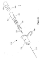
図12〜16全体を参照し、具体的には図12〜13を参照すると、安全な希釈剤が予め充填された注入器の第2の実施形態が示されている。注入装置110は、図1〜11で示された第1の実施形態10に関連して上述された構成要素と略同様の構成要素を含むものである。これらの構成要素は、両頭の針部材112、略円筒形の外筒130、圧縮バネ126、バネの付勢力に抗して針部材をリリース可能に保持する針リテイナ120、係止用クリップ200を含むものである。針部材112、は手前側の尖端114及び先端側の尖端116を有する。バネ126は針部材112を囲み、外筒の前端で外筒130の内面を押す。バネ126の後端は、針リテイナ120の内側を支持して針部材112及び針リテイナを後方に付勢する。
【0053】
上記実施形態とは対照的に、第2の実施形態は、第1の実施形態における上記のような中間壁や突刺可能なシールではなく、2種類の薬剤成分を隔てるための選択的に密閉可能なバイパス液体流路160を有するカートリッジ150を利用するものである。使用前、カートリッジ150内の中間シール170は2種類の薬剤成分154、158を隔てる。使用前、中間シール170は、液体流路を提供するバイパス流路160に近接して前方に移動され、2種類の薬剤成分154、158を混合することができるようにされる。その後、混合された成分は患者に注入される。
【0054】
図12、13を参照して、カートリッジ150の細部をより詳細に説明する。カートリッジは略円筒形の容器である。カートリッジの前端は突刺可能な前方シール180により密閉されている。カートリッジの後端は、ピストン143により密閉されており、カートリッジの内壁と液体密封シールを形成する。前方シール180とピストン143との中間で、中間シール170はカートリッジの内壁と液体密封シールを形成し、カートリッジを第1の成分158を受け入れる前方チャンバ156と第2の成分154を受け入れる後方チャンバ152の2個のチャンバに隔てる。
【0055】
カートリッジ150は、カートリッジの側面から外側に突出した泡のような液体流路160を含む。液体流路160には、カートリッジの直径が中間シールの直径よりも大きい個所が形成されている。液体流路160は軸方向に細長のチャネルであり、中間シール170の軸方向の長さよりも長く、好ましくは中間シールとピストン143が結合した長さよりも短いものである。
【0056】
液体流路160は泡のような突出物として示されているが、この液体流路はその他の構成で形成されてもよい。例えば、液体流路は、カートリッジ150の内壁に形成された凹部又は軸方向の溝であってもよく、この場合液体流路はカートリッジの外側表面から突出することはない。同様に、液体流路はカートリッジの内壁に形成された環状の凹部であってもよい。
【0057】
図12を参照すると、装置110は「格納」位置で示されている。この位置では、中間シール170は2種類の薬剤成分が混合されることを防止する。従って、密閉されたカートリッジ150は、所望の場合、薬剤成分の有効性を損なうことなく長期間保存することができる。保存位置において、中間シール170は液体流路160の後方に配置され、中間シールとカートリッジの内壁との間で中間シールの全周にわたり液体密封シールが形成される。
【0058】
注入装置110の保存中、図12〜13に示されるように、薬剤はカートリッジ150に格納された2種類の別々の成分に分けられる。具体的には、薬剤の第1の成分154は第1のチャンバ152に格納され、薬剤の第2の成分158は第2のチャンバ156に格納される。更に下記に示されるように、カートリッジが製造中に充填される場合、多少の空気が第2のチャンバ156内に残ることが好ましい。
【0059】
プランジャ140はカートリッジ150の後端に摺動可能に配置される。プランジャ140は、プラスチック成形されたプランジャロッド141とエラストマ−系ピストン143からなる。ピストン143は、液体密封シールをカートリッジの内壁と共に形成し、カートリッジ内で摺動させることができる。プランジャロッド141は、プランジャシール143に様々な方法で結合させることができる。本実施形態において、プランジャロッド141は外部ねじスレッド(external screw thread)を有し、プランジャシール143内の内側スレッドと係合わさるように構成されており、プランジャロッドとシールはねじ締めすることができる。
【0060】
図14を参照して、第1の薬剤要素154の第2チャンバ156への移動について説明する。中間シール170は、液体流路160に合わさるまで軸方向に前進されられる。その後、液体流路160はバイパス流路を提供し、これにより後方チャンバの成分を前方チャンバに注入することができる。前方チャンバは、好ましくは多少の空気(又は他の圧縮性の液体)を含んでいるので、前方チャンバの材料は圧縮されて中間シールが液体流路160に合わさるように前進させることができる。或いは、液体が後方チャンバから前方チャンバに移動した場合、前方チャンバは空気を前方チャンバから通風させる通気孔を含むものであってもよい。通気孔が含まれる場合、通気孔は密閉可能であり、混合された成分が注入中に漏れることを防ぐものであるのが好ましい。
【0061】
具体的には、カートリッジ内で2つの成分を混合させるためにプランジャ140はカートリッジ150に向かって軸方向に進められ、第1の成分154は中間シール170の後端に対して第1のチャンバ内152で押される。中間シール170にかけられるバックプレッシャは、中間シールとカートリッジ150の摩擦抵抗を上回るものであり、中間シールはカートリッジ内で前方に移動させられる。一旦中間シール170が移動して液体流路160に係合すると、図14に示されるように、流路が中間シールと液体流路の内壁との間に作られる。
【0062】
液体流路160は十分に大きく、第1の物質154は中間シール周辺を流れ、第2の物質158と混合される第2のチャンバ156に流入することができる。一旦第1の成分が第2のチャンバ156に完全に移動すると、図15に示されるように、プランジャシール143は中間シール170に隣接するまで進められる。中間シール170とピストン143が結合した軸方向の長さは、液体流路160の長さよりもわずかに長い。従って、中間シールとピストンは、液体流路を全長にわたり密閉する。これが第2のチャンバ156内の成分が混合中に逆流することを防止する。
【0063】
成分の混合が完了した後、係止用クリップ200は取り外されて薬剤が患者に注入できるようにされる。圧力がカートリッジ150に加えられ、薬剤が第2のチャンバ156から放出される。注入工程が完了すると、カートリッジ150は針リテイナ120を動作させる。その後、図16に示されるように、カートリッジ150にかけられる圧力は開放されて針部材を収納することができる。
【0064】
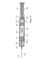
図17〜23全体を参照し、具体的には図17を参照すると、希釈剤が予め充填された安全な注入器の別の実施形態が一般に210で示されている。注入装置210は、両頭の針部材212、針部材を収納する略円筒形の外筒230及び略円筒形のカートリッジ250含む。外筒230は更に、圧縮バネ226及び針部材212をバネの付勢力に抗してリリース可能に保持する針リテイナ220を含む。針部材212は後尖端214及び先尖端216を有する。バネ226は、針部材212を囲み、外筒の前端で外筒230の内面に対して圧縮される。バネ226の後端は、針リテイナ220の内部で支持され、針部材212と針リテイナとを後方に付勢する。
【0065】
この実施形態において、薬剤成分の移動及び混合は、カートリッジがニードルハブ221に取り付けられる前、カートリッジ250内で行われる。カートリッジ250は、混合中、針アセンブリに結合されていないため、成分の混合中、針部材が不慮に引き込まれるリスクがない。結果として、外筒は他の実施形態のように係止用クリップを含まない。
【0066】
図18〜19を参照すると、カートリッジ250と外筒230はパッケージで供給され、2つは分解される。カートリッジ250は略円筒形の容器であり、ホウケイ酸塩などの薬品の品質を有するのガラス又はポリオレフィン若しくはポリエステルなどの硬質の不活性プラスチックから成形されてもよい。カートリッジキャップ253はカートリッジ250の先端側に配置される。カートリッジ250は、図12〜16で示されたカートリッジ150と同様の構成を有し、カートリッジの側方から外側に突出した泡のような液体流路260を含む。中間シール270は、カートリッジ250内で摺動可能に配置され、カートリッジを第1のチャンバ252と第2のチャンバ256とに隔てる。カートリッジ250の各チャンバには、装置210の製造中、所定量の薬剤成分が充填される。具体的には、第1のチャンバ252には薬剤の第1の成分254が予め充填され、第2のチャンバ256には第2の成分258が予め充填される。
【0067】
図20を参照すると、プランジャ240は、カートリッジ250の手前側に摺動可能に配置されている。プランジャ240は、プラスチック成形されたプランジャロッド241及びエラストマー系プランジャシール243からなる。プランジャ240がカートリッジ250に向けて軸方向に進められる場合、第1の成分254は第1のチャンバ252で中間シール270の後端に対して押される。中間シール270にかかるバックプレッシャが中間シールとカートリッジ250の摩擦抵抗を上回るに従って、中間シールがカートリッジ内で前方に移動される。一旦中間シール270が液体流路260と直線的に配置されると、流路が中間シールと液体流路内壁との間に形成され、第1の物質254は中間シールの近傍を通り第2の物質と混合される第2のチャンバ256に流れることができる。
【0068】
液体流路260は、第1の物質254が中間シールの近傍を通り第2の物質258と混合される第2のチャンバ256に流れるように十分な長さのものである。一旦第1の成分が第2のチャンバ256に完全に移動すると、図21に示されるように、プランジャシール243が中間シール270に近接するまで進められる。中間シール270とプランジャシール243が結合された軸方向の長さは、液体流路260の最長よりもわずかに長いものであり、これにより中間シールとプランジャシールは液体流路を全長にわたり閉鎖させる。これは、薬剤の混合中、第2のチャンバ256の中身が逆流することを防止する。
【0069】
再度図18を参照すると、カートリッジ250は、エラストマー系フロントシール280をカートリッジの先端側で含む。フロントシール280は、ポリイソプレンなどのセルフシールの生体適合性エラストマーで成形されてもよい。フロントシール280は略円筒形であり、カートリッジ内に配置された幅広の円筒形後端282と、カートリッジの前端から前方に突出して直径が縮小された前端284とを有する。後端282は、カートリッジ250の内径と同様の外径を有する。加えて、後端282は、複数の軸方向に離間した環状リブ286を有し、摩擦摺動でカートリッジの内部に係合し、液体密封シールを提供してカートリッジから液体が漏れることを防止する。
【0070】
フロントシール280の前端284は、外部スレッド288を外周に含む。また、先端側284は、浅い正面キャビティ290を含む。第2のチャンバ256と液連通している狭い穴292は、フロントシール280の手前側から延び、直径が縮小された先端側284内で終端する。正面キャビティ290と穴292の液連通は、突刺部材294で塞がれている。
【0071】
図19を参照すると、外筒230は略円筒形であり、先端側にテーパがかけられたノーズ232を有する。ノーズ232は、針部材212が挿通される開口を有している。加えて、ノーズ232は、針部材212が突出位置にある場合、ノーズにフィットして不慮の針刺しを防止する針カバー211を受け入れるように構成されている。外筒230の手前側は開いており、カートリッジ250を受け入れるようにされた円筒形ソケット234を形成する。カートリッジ250に取り付けられる前、外筒230の開口後端は円筒形の外筒キャップ233によって閉じられる。外筒は更に、針部材をリリース可能に保持するための針リテイナ220と協働する一対の保持開口238と、収納位置で針部材をロックするための係止用タブと協働する一対のロックアウトウインドウとを含む。
【0072】
針リテイナ220は、略円筒形の本体221と、本体221から径方向前方に延びる一対の保持アーム222とを含む。略円筒形の開口296は、針リテイナ本体221の手前側に配置される。開口296の内壁は、内側ねじスレッド298を含み、カートリッジ250内のフロントシール280の外側ねじスレッド288を受け入れるようにされている。
【0073】
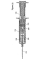
カートリッジキャップ253と外筒キャップ233は、カートリッジ250と外筒230から夫々取り外され、カートリッジと外筒を組み立てる準備が整う。カートリッジ250は、フロントシールの前端を外筒230の開口端を介して挿入し、カートリッジを時計回りに開口296にねじ込むことにより外筒230に結合される。図17に示されるように、カートリッジ250が外筒230に取り付けられることで針部材の手前側の尖端214はキャビティ290を通って部材294を突刺し、これによりカートリッジの第2のチャンバが針部材212と液連通されるように、フロントシール280の正面キャビティ290は針部材212と同軸上にあることが好ましい。
【0074】
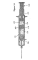
図17を参照すると、カートリッジ250は外筒230に結合され、カートリッジが外筒に向かって前方に進められることにより薬剤が患者に注入される。フロントシール280の手前側は、カートリッジ250の内側と滑りばめを形成するように構成されており、カートリッジが進む間、カートリッジはフロントシールを覆って摺動する。カートリッジ250が進められると、フロントシール280の後端は針リテイナ220を支持し、これによりカートリッジが進められる間、フロントシールの固定状態が維持される。同時に、第2のチャンバ256の後方で中間シール270はフロントシール280の方向に配置される。これが第2のチャンバ256内の薬剤量を減少させ、薬剤は針部材に移動し注入が容易にされる。注入の完了すると、図22に示されるように、中間シ−ル270はフロントシール280の後端で支持される。
【0075】
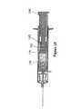
上記実施形態のように、針部材212は、針リテイナ220を作動させることにより収納される。具体的には、針部材212は、保持アーム222が外筒壁の保持開口238との係合から外され、バネ226が針部材212を後方に押すことにより引き込まれる。針リテイナ220を作動させるために、圧力がカートリッジ250にかけられ、図22に示されるように、カートリッジは針リテイナ本体221に進められる。進められている間、カートリッジ250の先端側は、針リテイナ本体221の先端側近傍に配置された円筒形のスリーブ300に係合する。リリーススリーブ300の内径及び外径は、好ましくはカートリッジ250の内径及び外径と等しいものであり、これによりカートリッジの先端側はスリーブの手前側と合わさる。カートリッジ250に係合する前、針リテイナに沿うリリーススリーブ300の軸方向への移動は、針リテイナ本体221上の環状液体流路223内でスライドする内側フランジ302により制限される。カートリッジ250がスリーブ300に係合した後、カートリッジの継続的な前進は、スリーブを軸方向前方に駆動させ保持アーム222に係合させる。図23に示されるように、リリーススリーブ300は、保持アームを径方向内側に曲げて保持開口238との係合を外させ、バネ226が針部材212を後方に押させることを可能にする。
【0076】
上記のように、第3の実施形態は、最初の2つの実施形態で示されたような引っかかりによる結合ではなく、フロントシール280と針リテイナ220のスレッド結合を含むものである。スレッド結合の使用は針リテイナ220の全長を増大させることができる。すなわち、カートリッジ250の先端側と保持アーム222との距離を増大させることができるものである。この増大した長さを調節する1つの方法は、外筒230の長さを増大することである。しかし、リリーススリーブ300と協働させて外筒230の長さを実質的に増大させる必要はない。リリーススリーブ300がカートリッジ250の延長として作用することにより、増大した距離を補填する。これは、装置210の全長を増大させる必要性を取り除く。リリーススリーブ300の長さは、フロントシール280と針リテイナ220のスレッド係合の長さよりもわずかに長いものであるのが好ましい。
【0077】
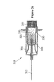
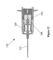
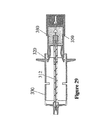
図24〜29全体を参照し、具体的には図24〜25を参照すると、希釈剤が予め充填された安全な注入器の第4の実施形態が示されている。注入装置310は、両頭の針部材312、針部材を収納する略円筒形の外筒330及び外筒の手前側内に取り付けられた略円筒形のカートリッジアセンブリ350を含むものである。上記実施形態のように、外筒は更に、圧縮バネ326と、バネの付勢に抗して針部材312をリリース可能に保持する針リテイナ320とを含むものである。装置310はまた、U形状の係止用クリップ400を外筒壁に含み、薬剤が装置310から不慮に放出されることを防止する。
【0078】
カートリッジアセンブリ350は、費用効率の良いプラスチックをアセンブリに使用する利点を提供する2つの設計を有するものである。カートリッジアセンブリ350は、開口手前側を有するフロントシリンダ351と、フロントシリンダの手前側に伸縮自在に取り付けられた先端側開口を有する後方シリンダ353とを含むものである。フロントシリンダ351は、カートリッジアセンブリ350を第1のチャンバ352と第2のチャンバ356に隔てる内壁360を含む。第1のチャンバ352は薬剤の第1の成分354を所定量保持するものであり、第2のチャンバ356は薬剤の第2の成分358を所定量保持するものである。フロントシリンダ351の手前側は、突刺可能なエラストマー系フロントシール380により閉じられている。
【0079】
多くの用途において、第2の成分358は、乾燥パウダー状の成分である。乾燥成分はガラス製の容器を必要とせず、成分の長期安定性を悪化させることなくプラスチック製の容器に格納することができる。ガラスよりもプラスチックから複雑な部分を成形した方がより費用効率が良いため、カートリッジアセンブリ350の複雑なガラス部分を最小限にすることが好ましい。この目的を達成するため、フロント及び後方シリンダ351、353を構成し、第1の成分354は後方シリンダ内に完全に格納され、第2の成分356はフロントシリンダ内に完全に格納される。この割り当てにより、フロントシリンダ351はより複雑な構造を含み、後方シリンダを単純なカップ形状の容器にすることが可能になる。従って、より複雑な前方シリンダは、乾燥した第2の成分358を第2のチャンバ356に格納するこれらの装置用に、費用効率の良いプラスチックから成形することができる。ガラスは、例え使用されるとしても、後方シリンダ353を成形するためにのみ使用されるのが好ましい。
【0080】
上記のように、後方シリンダ353はフロントシリンダ351の手前側に伸縮自在に取り付けられる。後方シールの後方部分の外径は後方シリンダ353の内径と略等しく、後方シリンダの内側に摩擦係合して液体密封シールを提供するものである。後方シリンダ353は、後方シリンダの手前側にかかる圧力に応じて後方シール340を覆って軸方向に摺動するようにされている。
【0081】
外筒330は後方シリンダ353の外径を調節するために十分な大きさの内径を有する。結果として、図25に示されるように、フロントシリンダ351の外壁は空隙によって外筒330の内壁から隔てられている。フロントシリンダ351は、フロントシリンダの外壁にある一対の対向する長手軸リブ355によって、より大きい外筒330と同心関係で維持されている。長手軸リブは図24に示されている。
【0082】
エラストマー系の後方シール340はフロントシリンダ351と後方シリンダ353の間に配置されている。後方シール340はフロントシリンダ351の開口手前側に一部に配置された小径端部342を含む。また、後方シール340は後方シリンダ353内に配置されたフランジ形344を含む。小径端部342とフランジ形344は、それぞれフロントシリンダ352及び後方シリンダ354の内側と摩擦摺動して係合する。この係合は液体密封シールを両シリンダの内側で提供する一方、後方シール340をどちらかのシリンダに対して移動させるものである。フロントシリンダ351に対する後方シール340の前進は、フロントシリンダの手前側で制限され、後方シールのフランジ部分に合わさって係合するように構成される。
【0083】
上記のように、フロントシリンダ351は内壁360を含む。内壁360は、カートリッジの後方開口端に近接し、後方シール340を受け入れるソケットを形成する。内壁360は壁360の中央に設けられたオリフィス362を含む。中空の突刺部材364はオリフィスに取り付けられ、後方シール340に向けて後方に延びる。加えて、通気口(vent opening)が内壁360に提供され、後方シリンダが進み後方シールが突刺される際、後方シール340と内壁の間で空気が通風されることが望ましい。
【0084】
後方シール340の先端側は、突刺部材364により突刺されるように構成された膜348で密閉されている。後方シール340は、後方シールの手前側を介して第1のチャンバ352と液連通で結合された中空の中間部分346を含む。一旦膜348が突刺されると、第1及び第2のチャンバ352、356が液連通で結合されるように、液体流路が突刺部材364と後方シール340を介して形成される。後方シール340は、ポリイソプレンなどの高伸長のセルフシール式生体適合性エラストマーで成形されてもよい。
【0085】
次に装置310の動作を説明する。わずかな絞り圧力が後方シリンダ353の手前側にかけられ、後方シリンダはフロントシリンダ351に向かって軸方向に進められる。これにより第1の成分354は、後方シール340と後方シリンダ353の密閉された手前側との間で押される。後方シリンダ353への継続的な圧力は、後方シール340にバックプレッシャをかけ、後方シールを突刺部材364に向けて前方に軸方向移動させる。このとき、膜348は突刺され、液体流路が第1及び第2のチャンバ352、356の間に形成される。
【0086】
後方シリンダ353はフロントシリンダ351に対して前方に進められ、第1の成分354を第1のチャンバ352から第2のチャンバ356に放出させる。図26に示されるように、一旦第1の成分354が完全に第1のチャンバ352から放出されると、後方シリンダの密閉された手前側が後方シールの手前側340に近接するまで、後方シリンダへの更なる圧力はフロントシリンダ350に対して後方シリンダを前方に進める。このとき、装置310を振ると、成分は第2のチャンバ356内で混合される。混合処理の間、カートリッジアセンブリ350の移動は係止用クリップ400により防止され、薬剤が不慮に放出される恐れは最小限にされる。
【0087】
要素が混合された後、係止用クリップ400は取り外される。その後、カートリッジアセンブリは前方に移動させられ、針部材312の後端が前方シール380を突刺する。そして、空気が前方チャンバから通風される。更なる圧力がカートリッジアセンブリにかけられ、薬剤が第2のチャンバ356から針部材312を介して放出される。図27に示されるように、注入工程の完了時、カートリッジアセンブリ350の手前側が針リテイナ320を作動させる。図28及び29に示されるように、その後、カートリッジアセンブリ350への圧力が開放されることにより、針部材312を収納することができる。
【0088】
ある場合には、カートリッジは成分単位で格納されることが望ましい。すなわち、後方シリンダ353は前方シリンダ351から取り外されるものであってもよい。使用前、後方シリンダ353は前方シリンダ351に取り付けられ、一体化したアセンブリは上記のように利用される。この場合、個々の後方コンテナ353は、前端を覆う個々のキャップを含むものであってもよい。同様に、前方シリンダ351は、後端を覆うキャップを含むものであってもよい。取り外し可能な後方シリンダ353は、予め処理された様々な薬剤成分を格納し、使用前、様々なコンビネーションで容易に組み合わせられるものであってもよい。
【0089】
本明細書で使用する用語および表現は、記述目的のものであり、制限目的のものではない。ここに示し説明している機能と同等のいかなる機能を排他する用語および表現も、使用する意図はない。ただし、本発明の要旨を変更しない範囲で種々の変形が可能であることが当業者により認識される。例えば、上記の実施形態は、使用後、針部材を収納するために自動的にリリースさせる一対の径方向に移動可能なアームを有する針リテイナを含むものである。しかし、この装置は、使用後、針部材を自動的に収納しても、しなくてもよい異なる針リテイナを利用するものに変形されてもよい。従って、本発明は本明細書に記載した特定の実施態様に制限されるものではないが、本発明の要旨を変更しない範囲での変形や修正を含むものである。
【図面の簡単な説明】
【0090】
発明の解決しようとする課題及び発明を実施するための最良の形態は、図面との関連で最もよく理解されるものである。
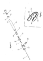
【図1】図1は、薬剤成分部分を格納する2個のチャンバ容器を有する予充填式のカートリッジ型注入器の斜視図である。
【図2】図2は、図1に示されたカートリッジ型注入器の分解斜視図である。
【図3】図3は、図2に示されたカートリッジ型注入器の係止用クリップの拡大図である。
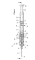
【図4】図4は、図1に示されたカートリッジ型注入器であり線4−4に沿う断面図である。
【図5】図5は、図4に示されたカートリッジ型注入器であり線5−5に沿う断面図である。
【図6】図6は、図1に示されたカートリッジ型注入器の断面図であり、薬剤成分部分を混合する前の装置である。
【図7】図7は、図1に示されたカートリッジ型注入器の断面図であり、混合後に注入を防止するためにロックされたカートリッジを有する装置である。
【図8】図8は、図1に示されたカートリッジ型注入器の断面図であり、混合後に注入するためロックが解かれたカートリッジを有する装置である。
【図9】図9は、図1に示されたカートリッジ型注入器の断面図であり、注入後であり、針部材が引き込む直前の装置である。
【図10】図10は、図1に示されたカートリッジ型注入器の断面図であり、針部材引き込み後の装置である。
【図11】図11は、図1に示されたカートリッジ型注入器の拡大断片の断面図であり、針部材が引き込まれた後、カートリッジと外筒の開封防止の結合である。
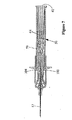
【図12】図12は、引込可能な針部材を有し、2個のチャンバを有する予充填式のカートリッジ型注入器の第2の実施形態の断面図である。
【図13】図13は、図12に示された装置であり線13−13に沿う断面図である。
【図14】図14は、図12に示された装置の断面図であり、カートリッジ内で薬剤成分を混合し、チャンバ間で薬剤成分を移動させている最中の装置である。
【図15】図15は、図12に示された装置の断面図であり、薬剤成分が混合された後の装置を示す。
【図16】図16は、図12に示された装置の断面図であり、針部材収納後の装置を示す。
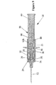
【図17】図17は、収納可能な針部材を有し、2個のチャンバを有する予充填式のカートリッジ型注入器の第3の実施形態の断面図である。
【図18】図18は、図17に示された装置のカートリッジ部分の断面図である。
【図19】図19は、図17に示された装置の断面図であり、カートリッジなしで使用前である。
【図20】図20は、図18に示されたカートリッジの断面図であり、薬剤成分を混合している最中の装置である。
【図21】図21は、図18に示された装置の断面図であり、薬剤成分を混合した後の装置である。
【図22】図22は、図17に示された装置の断面図であり、注入完了時の装置である。
【図23】図23は、図17に示された装置の断面図であり、針部材収納後の装置である。
【図24】図24は、収納可能な針部材を有し、2個のチャンバを有する予充填式のカートリッジ型注入器の第4の実施形態の拡大斜視図である。
【図25】図25は、図24に示された装置の断面図である。
【図26】図26は、図24に示された装置の断面図であり、薬剤成分を混合した後の装置である。
【図27】図27は、図24に示された装置の断面図であり、注入完了時の装置である。
【図28】図28は、図24に示された装置の断面図であり、針部材収納後の装置である。
【図29】図29は、図24に示された装置の断面図であい、針部材収納後の装置である。【Technical field】
[0001]
This application claims priority from US Provisional Application No. 60 / 275,568, filed March 13, 2001, and is hereby incorporated by reference.
[0002]
The present invention relates to a medical device, and more particularly to a medical device having a cartridge that stores separate drug components in two chambers, mixes these components, and ultimately delivers them to a patient.
[Background]
[0003]
A prefilled syringe stores and mixes separate drug components. Many of these syringes are referred to as “mixing syringes” and store the first component in the first compartment and the diluent or second component in the second compartment. These syringes can store two components separately until just before the syringe is used, and the components can be mixed in the syringe and administered directly to the patient when the syringe is used.
[0004]
Prefilled mixing syringes have advantages for a variety of drugs. Some drugs, such as antibiotics, vitamins and hormones, must be packaged and stored by ingredient to improve shelf life. These drugs need to be stored as powder elements and diluents, or as separate sets of solutions. The pre-filling type mixing syringe can store the medicine separately for each component until immediately before the medicine is administered. In addition, the pre-filling type mixing syringe removes the burden of measuring the drug component and mixing the diluent from another container.
[0005]
Despite these advantages, conventional mixing syringes have not provided a reliable safety feature to protect the syringe user from accidental needle sticks associated with injection. Specifically, conventional syringe assemblies have not provided a mixing syringe that functions integrally with an injection needle member that can be automatically protected upon completion of injection.
DISCLOSURE OF THE INVENTION
[Means for Solving the Problems]
[0006]
In view of the above circumstances, the present invention provides a pre-filled medical device for mixing different components and injecting a drug into a patient. This device includes a container having two chambers, such as a cartridge coupled to a needle member that automatically retracts after use. After storage, the contaminated needle tip is enclosed in the device to prevent accidental needle sticks.
[0007]
The device includes a hollow outer cylinder having a normally open rear end that surrounds the needle member and forms a socket. A two-chamber cartridge holding the drug component is adapted to engage the socket. Prior to use, the components are stored separately in two cartridge chambers. In use, a plunger located at the rear end of the cartridge is advanced into the cartridge and the two components are mixed together. Then, due to the pressure applied to the plunger, the drug mixture is introduced into the patient via the needle member.
[0008]
The injection needle member is movable between the protruding position and the storage position. At the protruding position, the tip of the needle member protrudes forward from the outer cylinder. In the storage position, the tip is enclosed in the outer cylinder. When the needle member is in the protruding position, the biasing element biases the needle member toward the storage position. The needle retainer holds the needle member releasably in the protruding position against the force of the biasing element. When the cartridge is disengaged from the needle retainer during the injection operation, the biasing element drives the needle member rearward toward the outer cylinder.
BEST MODE FOR CARRYING OUT THE INVENTION
[0009]
With reference to the entire drawing, and particularly FIGS. 1-11, an
[0010]
The
[0011]
The
[0012]
With reference to FIGS. 5-7, the
[0013]
The components of the
[0014]
As shown in FIG. 5, the
[0015]
The
[0016]
[0017]
Referring to FIG. 6, the
[0018]
As described above, the holding
[0019]
Referring again to FIGS. 4 and 5, the
[0020]
The front end of the
[0021]
With reference to FIGS. 5 and 6, the
[0022]
In the first position, the
[0023]
The
[0024]
To prepare the
[0025]
The coupling between the
[0026]
One-way coupling is facilitated by the rear taper shoulder of the
[0027]
Referring to FIG. 4, from the first position where the
[0028]
During storage of the
[0029]
Prior to use of the
[0030]
Like the
[0031]
[0032]
After the
[0033]
The
[0034]
Referring to FIGS. 1-3, the
[0035]
As the locking clip is inserted into the side wall of the
[0036]
After the drug components are mixed in the cartridge, the
[0037]
After the
[0038]
The automatic storage of the
[0039]
After the
[0040]
As shown in FIG. 10, when the
[0041]
The
[0042]
Each
[0043]
The front end of the
[0044]
As shown in FIG. 4, the linear elongated rear portion of each
[0045]
Each
[0046]
The
[0047]
The operation of the
[0048]
In a state where the
[0049]
Continued advancement of the
[0050]
During mixing, the
[0051]
Thereafter, the needle member is inserted into the patient, the
[0052]
With reference to FIGS. 12-16 in general, and in particular with reference to FIGS. 12-13, a second embodiment of an injector pre-filled with a safe diluent is shown. The
[0053]
In contrast to the above embodiment, the second embodiment is not an intermediate wall or pierceable seal as described above in the first embodiment, but can be selectively sealed to separate two types of drug components. A
[0054]
Details of the
[0055]
The
[0056]
The
[0057]
Referring to FIG. 12,
[0058]
During storage of the
[0059]
The
[0060]
With reference to FIG. 14, the movement of the
[0061]
Specifically, the
[0062]
The
[0063]
After mixing of the components is complete, the
[0064]
With reference generally to FIGS. 17-23, and in particular with reference to FIG. 17, another embodiment of a safe injector pre-filled with diluent is indicated generally at 210. FIG. The
[0065]
In this embodiment, the movement and mixing of the drug components occurs within the
[0066]
18-19, the
[0067]
Referring to FIG. 20, the
[0068]
The
[0069]
Referring again to FIG. 18, the
[0070]
The front end 284 of the
[0071]
Referring to FIG. 19, the
[0072]
The
[0073]
The
[0074]
Referring to FIG. 17, the
[0075]
As in the above embodiment, the
[0076]
As described above, the third embodiment includes a threaded connection between the
[0077]
Referring to FIGS. 24-29 in general, and specifically to FIGS. 24-25, a fourth embodiment of a safe injector pre-filled with diluent is shown. The
[0078]
The
[0079]
In many applications, the
[0080]
As described above, the
[0081]
The
[0082]
The elastomer-based
[0083]
As described above, the
[0084]
The distal end side of the
[0085]
Next, the operation of the
[0086]
The
[0087]
After the elements are mixed, the
[0088]
In some cases, it may be desirable to store cartridges in component units. That is, the
[0089]
The terms and expressions used herein are for descriptive purposes only and are not intended to be limiting. Terms and expressions exclusive of any function equivalent to that shown and described herein are not intended to be used. However, those skilled in the art will recognize that various modifications are possible without departing from the scope of the present invention. For example, the above embodiment includes a needle retainer having a pair of radially movable arms that are automatically released after use to house the needle member. However, the device may be modified to use a different needle retainer that may or may not automatically house the needle member after use. Accordingly, the present invention is not limited to the specific embodiments described in the present specification, but includes variations and modifications within the scope not changing the gist of the present invention.
[Brief description of the drawings]
[0090]
The problem to be solved and the best mode for carrying out the invention are best understood in connection with the drawings.
FIG. 1 is a perspective view of a prefilled cartridge-type injector having two chamber containers for storing a drug component portion.
FIG. 2 is an exploded perspective view of the cartridge type injector shown in FIG. 1;
FIG. 3 is an enlarged view of a locking clip of the cartridge type injector shown in FIG. 2;
FIG. 4 is a cross-sectional view taken along line 4-4 of the cartridge type injector shown in FIG.
FIG. 5 is a cross-sectional view of the cartridge type injector shown in FIG. 4 and taken along line 5-5.
6 is a cross-sectional view of the cartridge-type injector shown in FIG. 1 and shows the device before mixing the drug component portion.
FIG. 7 is a cross-sectional view of the cartridge type injector shown in FIG. 1 and is an apparatus having a cartridge that is locked to prevent injection after mixing.
FIG. 8 is a cross-sectional view of the cartridge-type injector shown in FIG. 1, with the device having the cartridge unlocked for injection after mixing.
FIG. 9 is a cross-sectional view of the cartridge type injector shown in FIG. 1 and shows the device after injection and just before the needle member is retracted.
FIG. 10 is a cross-sectional view of the cartridge type injector shown in FIG. 1, and shows the device after the needle member is retracted.
FIG. 11 is a cross-sectional view of an enlarged fragment of the cartridge type injector shown in FIG. 1, showing the unsealing connection between the cartridge and the outer cylinder after the needle member has been retracted.
FIG. 12 is a cross-sectional view of a second embodiment of a pre-filled cartridge-type injector having a retractable needle member and having two chambers.
FIG. 13 is a cross-sectional view of the device shown in FIG. 12, taken along line 13-13.
FIG. 14 is a cross-sectional view of the apparatus shown in FIG. 12, wherein the drug component is being mixed within the cartridge and the drug component is being moved between the chambers.
FIG. 15 is a cross-sectional view of the apparatus shown in FIG. 12, showing the apparatus after mixing of the drug components.
FIG. 16 is a cross-sectional view of the apparatus shown in FIG. 12, showing the apparatus after the needle member is stored.
FIG. 17 is a cross-sectional view of a third embodiment of a pre-filled cartridge type injector having a retractable needle member and two chambers.
FIG. 18 is a cross-sectional view of the cartridge portion of the apparatus shown in FIG.
FIG. 19 is a cross-sectional view of the apparatus shown in FIG. 17, prior to use without a cartridge.
FIG. 20 is a cross-sectional view of the cartridge shown in FIG. 18, showing the device during mixing of the drug components.
FIG. 21 is a cross-sectional view of the apparatus shown in FIG. 18, after mixing the drug components.
FIG. 22 is a cross-sectional view of the device shown in FIG. 17 when the injection is complete.
FIG. 23 is a cross-sectional view of the apparatus shown in FIG. 17 and shows the apparatus after the needle member is stored.
FIG. 24 is an enlarged perspective view of a fourth embodiment of a pre-filled cartridge injector having a retractable needle member and two chambers.
FIG. 25 is a cross-sectional view of the apparatus shown in FIG. 24.
FIG. 26 is a cross-sectional view of the device shown in FIG. 24, after mixing the drug components.
FIG. 27 is a cross-sectional view of the apparatus shown in FIG. 24, showing the apparatus upon completion of implantation.
FIG. 28 is a cross-sectional view of the apparatus shown in FIG. 24, showing the apparatus after the needle member is stored.
29 is a cross-sectional view of the apparatus shown in FIG. 24, and shows the apparatus after the needle member is stored.
Claims (41)
開口する手前側の端部及び先端側の端部を有する外筒と、;
第1の尖端を有し、前記第1の尖端が前記外筒から前方に突出する突出位置と、前記第1の尖端が封入されて前記第1の尖端との不慮の接触が防止される封入位置との間で移動可能な針部材と、;
前記針部材と液連通されるカートリッジであって、前記カートリッジは、:
第1の物質を含む第1のチャンバ、;
第2の物質を含む第2のチャンバ、;
前記第1のチャンバと第2のチャンバとの間の液体流通調整部、;及び
前記カートリッジ内でスライド可能に配置されたプランジャ、;
を有する前記カートリッジと、;
前記針部材を前記外筒に対して移動させる駆動力を提供し、前記第1の尖端を封入するための付勢要素と、;
前記針部材を前記突出位置でリリース可能に保持する針リテイナと、;
を有する前記医療用装置において、;
前記プランジャが前記第1のチャンバ内で軸方向に進められると、前記第1の物質が前記液体流通調整部を介して前記第2のチャンバに進められ、前記第1の物質は前記第2の物質と混合されて薬剤混合物が形成され、前記混合物が前記カートリッジから放出された後、前記プランジャ及び前記カートリッジの前記外筒に対する継続的な前進が前記針リテイナを作動させて前記針部材がリリースされ、これにより前記付勢要素が前記針部材を前記外筒に対して移動させて前記第1の尖端が封入される、
ことを特徴とする前記医療用装置。A medical device, wherein the medical device is:
An outer cylinder having an end on the front side and an end on the front end side to be opened;
Enclosed having a first tip, a protruding position where the first tip protrudes forward from the outer cylinder, and the first tip being sealed to prevent inadvertent contact with the first tip A needle member movable between positions;
A cartridge in fluid communication with the needle member, the cartridge comprising:
A first chamber containing a first substance;
A second chamber containing a second substance;
A liquid flow control section between the first chamber and the second chamber; and a plunger slidably disposed within the cartridge;
Said cartridge having:
A biasing element for providing a driving force for moving the needle member relative to the outer cylinder and enclosing the first point;
A needle retainer that releasably holds the needle member at the protruding position;
Said medical device comprising:
When the plunger is advanced in the axial direction in the first chamber, the first substance is advanced to the second chamber via the liquid flow adjusting unit, and the first substance is moved to the second chamber. After being mixed with the substance to form a drug mixture and the mixture is released from the cartridge, continuous advancement of the plunger and the cartridge relative to the outer cylinder actuates the needle retainer to release the needle member. In this way, the biasing element moves the needle member relative to the outer cylinder to enclose the first point.
The medical device as described above.
開口を有する前記第1及び第2のチャンバの間の壁部と、;
前記開口を介して配置され、前記第1のチャンバに突出する尖端を有する中空突刺構成要素と、;
前記突刺構成要素を介する液体流通路と、;
を有する前記液体流通調整部において、;
前記カートリッジが前記外筒に向けて軸方向に移動させられると、前記プランジャは前記プランジャが前記突刺構成要素により破られるまで移動し、前記突刺構成要素の液体流通路と同軸上にある前記プランジャを通過する流路が形成され、第1の物質を前記プランジャを介して前記第2のチャンバに流通させるものである。The medical device according to claim 1, wherein the liquid flow adjustment unit is;
A wall between the first and second chambers having an opening;
A hollow piercing component disposed through the opening and having a tip protruding into the first chamber;
A liquid flow path through the piercing component;
In the liquid flow control part having:
When the cartridge is moved axially toward the outer cylinder, the plunger moves until the plunger is broken by the piercing component, and the plunger is coaxial with the liquid flow path of the piercing component. A flow path is formed, and the first substance is circulated to the second chamber via the plunger.
開口を有する前記第1及び第2のチャンバの間のバリアと、;
前記開口を介して配置され、前記第1のチャンバに突出する尖端を有する中空突刺構成要素と、;
前記突刺構成要素を介する液体流通路と、;
前記第1のチャンバ内で軸方向に配置可能であり、前記突刺構成要素で突刺されることにより、前記第1及び第2のチャンバ間に液連通を提供する前記突刺可能な中間シールと、;
を有する前記液体流通調整部において、;
前記プランジャが前記外筒に向けて軸方向に移動させられると、前記突刺可能な中間シールは前記中間シールが前記突刺構成要素により破られるまで移動し、前記突刺構成要素の液体流通路と同軸上にある前記中間シールを通過する流路が形成され、第1の物質を前記中間シールを介して前記第2のチャンバに流通させるものである。The medical device according to claim 1, wherein the liquid flow adjustment unit is;
A barrier between the first and second chambers having an opening;
A hollow piercing component disposed through the opening and having a tip protruding into the first chamber;
A liquid flow path through the piercing component;
The pierceable intermediate seal that is axially displaceable within the first chamber and that is pierced by the piercing component to provide fluid communication between the first and second chambers;
In the liquid flow control part having:
When the plunger is moved axially toward the outer cylinder, the pierceable intermediate seal moves until the intermediate seal is broken by the piercing component and is coaxial with the liquid flow path of the piercing component. A flow path that passes through the intermediate seal is formed, and the first substance is circulated to the second chamber through the intermediate seal.
前記カートリッジ内で軸方向に移動可能な前記第1及び第2のチャンバ間にある中間シールと、:
前記カートリッジの前記側壁に設けられた細長の液体流路と、;
を有する前記液体流通調整部において、;
前記プランジャが前記外筒に向けて軸方向に移動させられると、前記中間シールは前記液体流路と直線的に位置決めされ、前記中間シールと前記液体流路の前記内壁との間に流路が形成され、前記第1の物質を前記中間シール周辺から前記第2チャンバに流通させるものである。The medical device according to claim 1, wherein the liquid flow adjusting unit is:
An intermediate seal between the first and second chambers movable axially within the cartridge;
An elongated liquid channel provided in the side wall of the cartridge;
In the liquid flow control part having:
When the plunger is moved in the axial direction toward the outer cylinder, the intermediate seal is linearly positioned with the liquid flow path, and a flow path is formed between the intermediate seal and the inner wall of the liquid flow path. The first material is formed and is circulated from the periphery of the intermediate seal to the second chamber.
開口する手前側の端部、先端側の端部、及び外筒の長手軸方向に対して垂直方向に位置する前記外筒の壁部を貫く開口を有する外筒と、;
第1の尖端を有し、前記第1の尖端が前記外筒から前方に突出する突出位置と、前記第1の尖端が保護され前記第1の尖端との不慮の接触が防止される保護位置との間で移動可能な針部材と、;
前記針部材と液連通するカートリッジであって、前記カートリッジは、:
第1の物質を含む第1のチャンバ、;
第2の物質を含む第2のチャンバ、;
前記第1のチャンバと前記第2のチャンバとを結合させる液体流通調整部、;及び
前記カートリッジ内でスライド可能に配置されたプランジャ;
を有する前記カートリッジと、;
前記針部材を前記外筒に対して移動させることができ、前記第1の尖端を封入するための動力を提供する付勢要素と、;
前記外筒に着脱可能に結合された係止用クリップと、;
を有する前記医療用装置において、;
前記プランジャが前記第1のチャンバ内で軸方向に進められると、前記第1の物質は前記第1の物質が前記第2の物質と混合され薬剤混合物が形成される前記第2のチャンバに前記液体流通調整部を介して進められ、前記係止用クリップが前記外筒から外されると、前記プランジャと前記カートリッジは前記外筒に対して更に進められて前記第2のチャンバから前記混合物が放出され、その後、前記カートリッジが軸方向に進められると前記針リテイナは係合から外され、前記付勢要素が前記針部材を前記外筒に対して移動させて前記第1の尖端が封入されるものである。A medical device, wherein the medical device is:
An outer cylinder having an opening penetrating through a wall portion of the outer cylinder positioned in a direction perpendicular to a longitudinal end direction of the outer cylinder;
A projecting position having a first tip, the first tip projecting forward from the outer cylinder, and a protected position where the first tip is protected and inadvertent contact with the first tip is prevented. A needle member movable between;
A cartridge in fluid communication with the needle member, the cartridge comprising:
A first chamber containing a first substance;
A second chamber containing a second substance;
A liquid flow control unit for coupling the first chamber and the second chamber; and a plunger slidably disposed in the cartridge;
Said cartridge having:
A biasing element capable of moving the needle member relative to the outer cylinder and providing power for enclosing the first point;
A locking clip detachably coupled to the outer cylinder;
Said medical device comprising:
When the plunger is advanced axially within the first chamber, the first substance is moved into the second chamber where the first substance is mixed with the second substance to form a drug mixture. When the locking clip is removed from the outer cylinder through the liquid flow adjusting portion, the plunger and the cartridge are further advanced relative to the outer cylinder so that the mixture is discharged from the second chamber. When the cartridge is released and then the cartridge is advanced in the axial direction, the needle retainer is disengaged, and the biasing element moves the needle member relative to the outer cylinder to enclose the first point. Is.
開口を有する前記第1及び第2のチャンバの間のバリアと、;
前記開口を介して配置され、前記第1のチャンバに突出する尖端を有する中空突刺構成要素と、;
前記突刺構成要素を介する液体流通路と、;
前記第1のチャンバ内で軸方向に配置可能であり、前記突刺構成要素で突刺されることにより前記第1及び第2のチャンバ間に液連通を提供する前記穴開け可能な中間シールと、;
を有する前記液体流通調整部において、;
前記プランジャが前記外筒に向けて最初に軸方向に移動させられると、前記突刺可能な中間シールが移動して前記突刺構成要素と接触し、前記中間シールに穴が開けられ、前記突刺構成要素内の液体流通路の直線上にある中間シールを貫通する流路が形成され、前記第1の物質を前記中間シールを介して前記第2のチャンバに流通させるものである。23. The medical device according to claim 22, wherein the liquid flow adjustment part is;
A barrier between the first and second chambers having an opening;
A hollow piercing component disposed through the opening and having a tip protruding into the first chamber;
A liquid flow path through the piercing component;
The pierceable intermediate seal that is axially displaceable within the first chamber and that is pierced by the piercing component to provide fluid communication between the first and second chambers;
In the liquid flow control part having:
When the plunger is first moved in the axial direction toward the outer cylinder, the pierceable intermediate seal moves to contact the piercing component, and the intermediate seal is perforated, and the piercing component A flow path is formed through an intermediate seal that is on a straight line of the liquid flow path inside, and the first substance is circulated through the intermediate seal to the second chamber.
前記カートリッジ内で軸方向に移動可能な前記第1及び第2のチャンバ間にある中間シールと、:
前記中間シールと前記カートリッジの先端側の端部との間にある前記カートリッジの前記側壁に設けられた細長の液体流路と、;
を有する前記液体流通調整部において、;
前記プランジャが前記外筒に向けて軸方向に移動させられると、前記中間シールは前記液体流路と直線的に位置決めされ、前記中間シールと前記液体流路の前記内壁との間に流路が形成され、前記第1の物質を前記中間シール周辺から前記第2チャンバに流通させるものである。23. The medical device according to claim 22, wherein the liquid flow adjustment part is;
An intermediate seal between the first and second chambers movable axially within the cartridge;
An elongated liquid channel provided in the side wall of the cartridge between the intermediate seal and the end of the cartridge on the front end side;
In the liquid flow control part having:
When the plunger is moved in the axial direction toward the outer cylinder, the intermediate seal is linearly positioned with the liquid flow path, and a flow path is formed between the intermediate seal and the inner wall of the liquid flow path. The first material is formed and flows from the periphery of the intermediate seal to the second chamber.
開口する手前側の端部及び先端側の端部を有する外筒と、;
第1の尖端を有し、前記第1の尖端が前記外筒から前方に突出する突出位置と、前記第1の尖端が保護され前記第1の尖端との不慮の接触が防止される保護位置との間で移動可能な針部材と、;
前記針部材と液連通するカートリッジであって、前記カートリッジは:
第1の物質を含む第1のチャンバ、;
第2の物質を含む第2のチャンバ、;
前記第1のチャンバと前記第2のチャンバとの間の液体流通調整部、;及び、
前記針部材を前記外筒に対して移動させることができ前記第1の尖端を保護する動力を提供する付勢要素と、;
を有する前記カートリッジと、;
前記針部材を前記突出位置でリリース可能に保持する針リテイナと、;
を有する前記医療用装置において、;
前記液体流通調整部は、使用前、前記第1及び第2の物質は隔離され続けるようにされており、注入前、前記第1及び第2の物質は混合されるようにされており、使用後、前記針部材は前記保護位置に移動させられるものである。A medical device, the medical device comprising:
An outer cylinder having an end on the front side and an end on the front end side to be opened;
A projecting position having a first tip, the first tip projecting forward from the outer cylinder, and a protected position where the first tip is protected and inadvertent contact with the first tip is prevented. A needle member movable between;
A cartridge in fluid communication with the needle member, wherein the cartridge is:
A first chamber containing a first substance;
A second chamber containing a second substance;
A liquid flow controller between the first chamber and the second chamber; and
A biasing element capable of moving the needle member relative to the outer tube and providing power to protect the first point;
Said cartridge having:
A needle retainer that releasably holds the needle member at the protruding position;
Said medical device comprising:
The liquid flow control unit is configured so that the first and second substances are kept isolated before use, and the first and second substances are mixed before injection. Thereafter, the needle member is moved to the protected position.
第1の薬剤成分を含む第1のチャンバ、第2の薬剤成分を含む第2のチャンバ、及び針部材を有する注入装置を提供する工程と;
前記第2の薬剤成分を前記第1のチャンバから前記第2のチャンバに送る工程と;
前記第1及び第2の成分を混合して薬剤混合物を形成する工程と;
前記薬剤混合物を前記チャンバから放出させる工程と;
前記薬剤液が放出された後、前記針部材を収納して前記針部材を接触から保護する工程と;
を有する前記薬剤を注入する方法。A method of injecting a medicament, wherein the injecting step comprises:
Providing an injection device having a first chamber containing a first drug component, a second chamber containing a second drug component, and a needle member;
Sending the second drug component from the first chamber to the second chamber;
Mixing the first and second components to form a drug mixture;
Releasing the drug mixture from the chamber;
Storing the needle member to protect the needle member from contact after the drug solution is released;
A method of injecting the drug having the following.
Applications Claiming Priority (2)
| Application Number | Priority Date | Filing Date | Title |
|---|---|---|---|
| US27556801P | 2001-03-13 | 2001-03-13 | |
| PCT/US2002/007712 WO2002072171A2 (en) | 2001-03-13 | 2002-03-13 | Pre-filled safety diluent injector |
Publications (1)
| Publication Number | Publication Date |
|---|---|
| JP2005508202A true JP2005508202A (en) | 2005-03-31 |
Family
ID=23052867
Family Applications (1)
| Application Number | Title | Priority Date | Filing Date |
|---|---|---|---|
| JP2002571129A Pending JP2005508202A (en) | 2001-03-13 | 2002-03-13 | Prefilled safety diluent injector |
Country Status (11)
| Country | Link |
|---|---|
| US (1) | US6981963B2 (en) |
| EP (1) | EP1377326B1 (en) |
| JP (1) | JP2005508202A (en) |
| CN (1) | CN1509195A (en) |
| AT (1) | ATE399033T1 (en) |
| BR (1) | BR0208068A (en) |
| CA (1) | CA2440889A1 (en) |
| DE (1) | DE60227245D1 (en) |
| ES (1) | ES2307736T3 (en) |
| MX (1) | MXPA03008268A (en) |
| WO (1) | WO2002072171A2 (en) |
Cited By (1)
| Publication number | Priority date | Publication date | Assignee | Title |
|---|---|---|---|---|
| JP2015536204A (en) * | 2012-11-30 | 2015-12-21 | ユニトラクト シリンジ プロプライエタリイ リミテッドUnitract Syringe Pty Ltd | Compound plunger device for dual chamber mixing syringe |
Families Citing this family (51)
| Publication number | Priority date | Publication date | Assignee | Title |
|---|---|---|---|---|
| WO2001051024A2 (en) * | 2000-01-11 | 2001-07-19 | Roland Bodmeier | Implantation kit comprising a support phase and a solvent |
| JP4112851B2 (en) * | 2001-11-27 | 2008-07-02 | テルモ株式会社 | Two-chamber prefilled syringe |
| FR2842428B1 (en) * | 2002-07-19 | 2004-10-08 | Becton Dickinson France | DEVICE FOR INJECTING A PRODUCT, ESPECIALLY FOR MEDICAL USE |
| US20050096597A1 (en) * | 2003-11-03 | 2005-05-05 | Becton, Dickinson And Company | Safety shield system for a syringe |
| US7497847B2 (en) * | 2003-11-03 | 2009-03-03 | Becton, Dickinson And Company | Safety shield system for a syringe |
| US7344517B2 (en) * | 2004-01-20 | 2008-03-18 | Becton, Dickinson And Company | Syringe having a retractable needle |
| US20050171483A1 (en) * | 2004-02-03 | 2005-08-04 | Dennis Williams | Needle cover extractor |
| WO2005079888A2 (en) * | 2004-02-19 | 2005-09-01 | Aditech Pharma Ab | Delivery device for delivering pyy |
| US8088105B2 (en) * | 2004-03-29 | 2012-01-03 | Fertiligent Ltd. | Syringe pump |
| FR2869533B1 (en) * | 2004-05-03 | 2006-07-28 | Sedat Sa | SYRINGE FOR MEDICAL INTERVENTIONS AND NECESSARY FOR RECONSTITUTION OF EXTEMPORANEOUS SUBSTANCES COMPRISING SUCH A SYRINGE |
| AT500930B1 (en) | 2004-10-25 | 2007-03-15 | Pharma Consult Ges M B H & Co | METHOD AND DEVICE FOR LYOPHILIZING, RECONSTITUTING AND DISTRIBUTING A RECONSTITUTED ACTIVE SUBSTANCE |
| WO2006058435A2 (en) * | 2004-12-03 | 2006-06-08 | Duoject Medical Systems Inc. | Cartridge, device and method for pharmaceutical storage, mixing and delivery |
| CH699723B1 (en) * | 2005-04-25 | 2010-04-30 | Tecpharma Licensing Ag | A device for administering a fluid product. |
| US7780695B2 (en) * | 2005-06-30 | 2010-08-24 | Codman & Shurtleff, Inc. | Chemically based vascular occlusion device deployment |
| CN100368030C (en) * | 2005-11-30 | 2008-02-13 | 湖南千山制药机械股份有限公司 | Two-chamber prefilled syringe and its prefilling method |
| TW200743500A (en) * | 2006-05-26 | 2007-12-01 | ming-zheng Xu | Disposable syringe |
| CA2574746A1 (en) * | 2007-01-22 | 2008-07-22 | Duoject Medical Systems Inc. | Syringe having venting structure and method for mixing two substances in a syringe |
| US20080221584A1 (en) * | 2007-03-06 | 2008-09-11 | Downer David A | Lens Delivery System |
| CA2687962C (en) * | 2007-06-13 | 2014-08-05 | Duoject Medical Systems Inc. | Device for transferring fluids from a cartridge to a container |
| JP2011512911A (en) * | 2008-02-28 | 2011-04-28 | メッドミックス システムズ アーゲー | Single chamber device for drawing and dispensing components |
| GB2462811B (en) * | 2008-08-18 | 2012-08-15 | Medical House Ltd | Improved autoinjector |
| WO2010104858A2 (en) * | 2009-03-09 | 2010-09-16 | Purdue Research Foundation | Compact device for rapidly mixing and delivering substances to a patient |
| IL197761A0 (en) * | 2009-03-23 | 2009-12-24 | Moshe Zalsman | Capsule for mixing together two flowable materials, and kits including such capsules, particularly useful in dentistry |
| US8998880B2 (en) * | 2009-08-06 | 2015-04-07 | Duoject Medical Systems Inc. | Airless mixing with a by-pass syringe |
| CN102753275B (en) * | 2010-02-12 | 2015-05-13 | 药物混合系统股份公司 | Discharge device having a locking element |
| JP2013523202A (en) | 2010-03-25 | 2013-06-17 | ニュー インジェクション システムズ リミテッド | Syringe |
| CA2742555A1 (en) * | 2011-06-10 | 2012-12-10 | Duoject Medical Systems Inc. | Injection device |
| CA2745320A1 (en) * | 2011-07-06 | 2013-01-06 | Duoject Medical Systems Inc. | Reconstitution device |
| US8672883B2 (en) | 2011-07-11 | 2014-03-18 | C. Garyen Denning | Fluid delivery device and methods |
| DK2739328T3 (en) | 2011-08-05 | 2018-07-23 | Unl Holdings Llc | DOUBLE CAMERA MIXING DEVICE FOR A SPRAY |
| US9821118B2 (en) | 2011-09-02 | 2017-11-21 | Unl Holdings Llc | Automatic reconstitution for dual chamber syringe |
| EP2776098B1 (en) | 2011-11-07 | 2020-03-04 | Safety Syringes, Inc. | Contact trigger release needle guard |
| CN103100128A (en) * | 2012-05-14 | 2013-05-15 | 中国人民解放军成都军区总医院 | Compound medicine administration method |
| CN105878017A (en) * | 2012-07-06 | 2016-08-24 | 纳克斯梅德控股公司 | Redissolution method and redissolution device |
| WO2014080020A1 (en) | 2012-11-23 | 2014-05-30 | New Injection Systems Ltd | Auto-injector assembly |
| DE102012024371A1 (en) * | 2012-12-13 | 2014-06-18 | Schott Ag | Storage device Storage of liquid media, in particular medicines and methods for dispensing liquid media |
| EP2742963A1 (en) * | 2012-12-17 | 2014-06-18 | Sanofi-Aventis Deutschland GmbH | Drug delivery device |
| CN105517603B (en) | 2013-06-04 | 2019-12-24 | 尤尼特拉克特注射器控股有限公司 | Actuation mechanism for a dual chamber mixing syringe |
| AU2014318264B2 (en) | 2013-09-16 | 2018-10-04 | Zoetis Services Llc | Assembly for sequentially delivering substances, and associated methods |
| US9480465B2 (en) * | 2014-01-06 | 2016-11-01 | Richard Hwang | Organism paracentesis device and method thereof |
| EP2905041A1 (en) * | 2014-02-11 | 2015-08-12 | Sulzer Mixpac AG | Syringe |
| US20170153165A1 (en) * | 2015-11-30 | 2017-06-01 | Chidozie O. Nwadigo | Syringe assembly for withdrawing two separate portions of fluid following a single engagement with fluid port |
| GB2556088A (en) * | 2016-11-18 | 2018-05-23 | Owen Mumford Ltd | Packaging and devices for mixing medicament substances |
| US11666708B2 (en) * | 2017-07-24 | 2023-06-06 | Noble International, Inc. | Medicament training device with plunger limiting mechanism |
| IL261024B2 (en) * | 2018-08-07 | 2023-07-01 | Equashield Medical Ltd | A septum holder with moveable septum |
| CN110811906B (en) * | 2019-11-21 | 2021-10-15 | 江苏农牧科技职业学院 | Medical advanced immunization device for pseudorabies of piglets in positive pig farm |
| EP4072624A1 (en) * | 2019-12-11 | 2022-10-19 | Sanofi | Injection device |
| CN110934745B (en) * | 2019-12-23 | 2022-04-22 | 重庆市潼南区中医院 | Safe and rapid medicine preparation injector |
| CN112791271B (en) * | 2021-01-04 | 2023-07-21 | 达尔塔(南京)智能装备有限公司 | First-aid mask for cyanosis patient for ambulance |
| CN115607446A (en) * | 2022-07-01 | 2023-01-17 | 湛江健力源医疗用品有限公司 | Air pressure balanced center needle type totally enclosed safety dispensing device |
| CN115448471B (en) * | 2022-10-19 | 2023-08-15 | 墨之道(山东)测控设备有限公司 | A accurate dosing device of scale inhibitor for circulating cooling water |
Family Cites Families (48)
| Publication number | Priority date | Publication date | Assignee | Title |
|---|---|---|---|---|
| US34845A (en) * | 1862-04-01 | Improved female supporters | ||
| US3563240A (en) * | 1966-07-20 | 1971-02-16 | Jules Silver | Dual unit syringe |
| US3563373A (en) * | 1967-10-06 | 1971-02-16 | Paul E Paulson | Hypodermic syringe assembly |
| US3570486A (en) * | 1968-10-14 | 1971-03-16 | Horizon Ind Ltd | Mixing syringe |
| US3724460A (en) * | 1968-11-14 | 1973-04-03 | American Home Prod | Disposable cartridge for admixing two components of injectable medicament |
| US3636950A (en) * | 1968-11-14 | 1972-01-25 | American Home Prod | Disposable cartridge for admixing two components of injectable medicament |
| US3659749A (en) * | 1970-04-28 | 1972-05-02 | Boris Schwartz | Intermixing syringe |
| US3785379A (en) * | 1971-08-12 | 1974-01-15 | M Cohen | Syringe for injection of freshly mixed liquid-powder |
| US3911916A (en) * | 1971-10-29 | 1975-10-14 | Peter A Stevens | Sequential injection syringe |
| US3946732A (en) * | 1973-08-08 | 1976-03-30 | Ampoules, Inc. | Two-chamber mixing syringe |
| US4031895A (en) * | 1976-04-05 | 1977-06-28 | Porter Robert E | Syringe assembly package |
| US4055177A (en) * | 1976-05-28 | 1977-10-25 | Cohen Milton J | Hypodermic syringe |
| US4059109A (en) * | 1976-07-27 | 1977-11-22 | Tischlinger Edward A | Mixing and dispensing disposable medicament injector |
| US4122943A (en) * | 1976-10-21 | 1978-10-31 | Jules Silver | Valved two compartment dispensing container |
| US4159066A (en) * | 1977-04-29 | 1979-06-26 | Jules Silver | Package for dispensing a plurality of flowable materials |
| US4171698A (en) * | 1977-08-15 | 1979-10-23 | Abbott Laboratories | Prefilled two-compartment syringe |
| NL180634C (en) * | 1977-12-23 | 1987-04-01 | Duphar Int Res | INJECTION SYRINGE AND NEEDLE HOLDER FOR THIS. |
| US4315570A (en) * | 1979-01-04 | 1982-02-16 | Jules Silver | Two-compartment container with means for dispersing contents of one compartment into the other compartment |
| US4405317A (en) * | 1981-09-30 | 1983-09-20 | The West Company | Syringe assembly |
| US4413991A (en) * | 1982-03-18 | 1983-11-08 | Schmitz John B | Dual dose ampule |
| US4424057A (en) * | 1982-04-01 | 1984-01-03 | House Hugh A | Wet-dry syringe |
| US4581016A (en) * | 1984-02-29 | 1986-04-08 | Gettig Pharmaceutical Instrument Co. | Dual cartridge wet/dry syringe |
| DE3417757C2 (en) * | 1984-05-12 | 1994-11-10 | Lucas Dieter Dr | Hypodermic syringe |
| US4689042A (en) * | 1985-05-20 | 1987-08-25 | Survival Technology, Inc. | Automatic medicament ingredient mixing and injecting apparatus |
| US4861335A (en) * | 1985-07-26 | 1989-08-29 | Duoject Medical Systems Inc. | Syringe |
| US4702737A (en) * | 1986-07-14 | 1987-10-27 | Pizzino Joanne L | Dual dose syringe |
| US4693706A (en) * | 1986-08-11 | 1987-09-15 | Mark L. Anderson | Two compartment mixing syringe |
| US5364369A (en) * | 1987-07-08 | 1994-11-15 | Reynolds David L | Syringe |
| US4883471A (en) * | 1988-08-16 | 1989-11-28 | Braginetz Paul A | Disposable shielded medical syringe |
| DE3916101A1 (en) * | 1989-05-17 | 1990-11-22 | Vetter & Co Apotheker | SYRINGE FOR MEDICAL PURPOSES |
| US4979941A (en) * | 1989-12-05 | 1990-12-25 | International Medication Systems, Limited | Device suitable for mixing medication |
| US5114411A (en) * | 1990-11-19 | 1992-05-19 | Habley Medical Technology Corporation | Multi-chamber vial |
| US5360410A (en) * | 1991-01-16 | 1994-11-01 | Senetek Plc | Safety syringe for mixing two-component medicaments |
| US5281198A (en) * | 1992-05-04 | 1994-01-25 | Habley Medical Technology Corporation | Pharmaceutical component-mixing delivery assembly |
| US5531683A (en) * | 1992-08-13 | 1996-07-02 | Science Incorporated | Mixing and delivery syringe assembly |
| NZ258210A (en) * | 1992-12-01 | 1997-06-24 | Tetsuro Higashikawa | Syringe with a plurality of chambers |
| US5489267A (en) * | 1994-01-03 | 1996-02-06 | Moreno; Saul | Double chamber disposable syringe |
| FR2715071B1 (en) * | 1994-01-17 | 1996-03-01 | Aguettant Lab | Automatic drug injector. |
| US5522804A (en) * | 1994-02-15 | 1996-06-04 | Lynn; Lawrence A. | Aspiration, mixing, and injection syringe |
| IT233201Y1 (en) * | 1994-03-24 | 2000-01-26 | Bracco Spa | TWO-COMPONENT DEVICE FOR THE ADMINISTRATION OF DRUGS |
| EP0692235A1 (en) * | 1994-07-14 | 1996-01-17 | International Medication Systems (U.K.) Ltd. | Mixing & dispensing apparatus |
| US5685846A (en) * | 1995-02-27 | 1997-11-11 | Schott Parenta Systems, Inc. | Dual chamber internal by-pass syringe assembly |
| US5637087A (en) * | 1995-03-22 | 1997-06-10 | Abbott Laboratories | Prefilled, two-constituent syringe |
| JPH08280800A (en) * | 1995-04-12 | 1996-10-29 | Nissho Corp | Prefilled syringe for two-liquid injection |
| US5891087A (en) * | 1996-03-15 | 1999-04-06 | Takeda Chemical Industries, Ltd. | Mixing syringe |
| US5865798A (en) * | 1996-06-28 | 1999-02-02 | Becton Dickinson France, S.A. | Stopper assembly having bypass features for use in a multi-chamber syringe barrel |
| CA2340655A1 (en) | 1998-08-28 | 2000-03-09 | Michael J. Botich | Fluid infusion device with retractable needle |
| US6641565B1 (en) * | 1998-11-13 | 2003-11-04 | Elan Pharma International Limited | drug delivery systems and methods |
-
2002
- 2002-03-13 US US10/099,933 patent/US6981963B2/en not_active Expired - Lifetime
- 2002-03-13 EP EP02715114A patent/EP1377326B1/en not_active Expired - Lifetime
- 2002-03-13 WO PCT/US2002/007712 patent/WO2002072171A2/en active Application Filing
- 2002-03-13 CN CNA028098528A patent/CN1509195A/en active Pending
- 2002-03-13 AT AT02715114T patent/ATE399033T1/en not_active IP Right Cessation
- 2002-03-13 BR BR0208068-0A patent/BR0208068A/en not_active Application Discontinuation
- 2002-03-13 MX MXPA03008268A patent/MXPA03008268A/en unknown
- 2002-03-13 JP JP2002571129A patent/JP2005508202A/en active Pending
- 2002-03-13 ES ES02715114T patent/ES2307736T3/en not_active Expired - Lifetime
- 2002-03-13 CA CA002440889A patent/CA2440889A1/en not_active Abandoned
- 2002-03-13 DE DE60227245T patent/DE60227245D1/en not_active Expired - Fee Related
Cited By (3)
| Publication number | Priority date | Publication date | Assignee | Title |
|---|---|---|---|---|
| JP2015536204A (en) * | 2012-11-30 | 2015-12-21 | ユニトラクト シリンジ プロプライエタリイ リミテッドUnitract Syringe Pty Ltd | Compound plunger device for dual chamber mixing syringe |
| US10130768B2 (en) | 2012-11-30 | 2018-11-20 | Unl Holdings Llc | Combination plunger device for a dual chamber mixing syringe |
| US11191902B2 (en) | 2012-11-30 | 2021-12-07 | Unl Holdings Llc | Combination plunger device for a dual chamber mixing syringe |
Also Published As
| Publication number | Publication date |
|---|---|
| CA2440889A1 (en) | 2002-09-19 |
| US6981963B2 (en) | 2006-01-03 |
| WO2002072171A9 (en) | 2002-10-31 |
| BR0208068A (en) | 2005-04-19 |
| EP1377326A4 (en) | 2004-12-15 |
| CN1509195A (en) | 2004-06-30 |
| ES2307736T3 (en) | 2008-12-01 |
| WO2002072171A3 (en) | 2003-10-30 |
| EP1377326B1 (en) | 2008-06-25 |
| US20020177805A1 (en) | 2002-11-28 |
| DE60227245D1 (en) | 2008-08-07 |
| MXPA03008268A (en) | 2004-10-15 |
| ATE399033T1 (en) | 2008-07-15 |
| WO2002072171A2 (en) | 2002-09-19 |
| EP1377326A2 (en) | 2004-01-07 |
Similar Documents
| Publication | Publication Date | Title |
|---|---|---|
| JP2005508202A (en) | Prefilled safety diluent injector | |
| US7470258B2 (en) | Pre-filled safety vial injector | |
| US7004929B2 (en) | Safety pre-filled cartridge injector | |
| US7338469B2 (en) | Pre-filled retractable needle injection device | |
| US6039713A (en) | Pre-filled retractable needle injection device | |
| US11065388B2 (en) | Medicament packaging | |
| KR19980018908A (en) | Cartridge for an injection device | |
| JPH10295814A (en) | Cannula tight sealing shield assembly | |
| AU2017376144B2 (en) | Caps for integrated fill and inject of safety needle devices | |
| GB2556633A (en) | Medicament delivery device | |
| GB2556088A (en) | Packaging and devices for mixing medicament substances | |
| EP1066071B1 (en) | Pre-filled retractable needle injection device | |
| JPH11169460A (en) | Two-chamber type prefilled syringe | |
| WO2003084589A1 (en) | Safety pre-filled cartridge injector | |
| GB2556091A (en) | Medicament delivery device and system | |
| AU2002247333A1 (en) | Pre-filled safety diluent injector | |
| AU2002244294A1 (en) | Pre-filled safety vial injector | |
| WO2004043514A2 (en) | Pre-filled retractable needle injection device |