JP2011512911A - Single chamber device for drawing and dispensing components - Google Patents
Single chamber device for drawing and dispensing components Download PDFInfo
- Publication number
- JP2011512911A JP2011512911A JP2010547932A JP2010547932A JP2011512911A JP 2011512911 A JP2011512911 A JP 2011512911A JP 2010547932 A JP2010547932 A JP 2010547932A JP 2010547932 A JP2010547932 A JP 2010547932A JP 2011512911 A JP2011512911 A JP 2011512911A
- Authority
- JP
- Japan
- Prior art keywords
- rod
- mixing
- plunger
- piston
- mixing rod
- Prior art date
- Legal status (The legal status is an assumption and is not a legal conclusion. Google has not performed a legal analysis and makes no representation as to the accuracy of the status listed.)
- Pending
Links
- 238000007789 sealing Methods 0.000 claims description 3
- 239000000203 mixture Substances 0.000 abstract description 8
- 239000002639 bone cement Substances 0.000 abstract description 2
- 239000007788 liquid Substances 0.000 description 4
- 239000000843 powder Substances 0.000 description 3
- 239000006072 paste Substances 0.000 description 2
- 230000001419 dependent effect Effects 0.000 description 1
- 238000005516 engineering process Methods 0.000 description 1
- 239000004615 ingredient Substances 0.000 description 1
- 239000000463 material Substances 0.000 description 1
- 238000000034 method Methods 0.000 description 1
- 230000004048 modification Effects 0.000 description 1
- 238000012986 modification Methods 0.000 description 1
- 238000002360 preparation method Methods 0.000 description 1
- 238000003825 pressing Methods 0.000 description 1
Images


Classifications
-
- B—PERFORMING OPERATIONS; TRANSPORTING
- B05—SPRAYING OR ATOMISING IN GENERAL; APPLYING FLUENT MATERIALS TO SURFACES, IN GENERAL
- B05C—APPARATUS FOR APPLYING FLUENT MATERIALS TO SURFACES, IN GENERAL
- B05C17/00—Hand tools or apparatus using hand held tools, for applying liquids or other fluent materials to, for spreading applied liquids or other fluent materials on, or for partially removing applied liquids or other fluent materials from, surfaces
- B05C17/005—Hand tools or apparatus using hand held tools, for applying liquids or other fluent materials to, for spreading applied liquids or other fluent materials on, or for partially removing applied liquids or other fluent materials from, surfaces for discharging material from a reservoir or container located in or on the hand tool through an outlet orifice by pressure without using surface contacting members like pads or brushes
- B05C17/00553—Hand tools or apparatus using hand held tools, for applying liquids or other fluent materials to, for spreading applied liquids or other fluent materials on, or for partially removing applied liquids or other fluent materials from, surfaces for discharging material from a reservoir or container located in or on the hand tool through an outlet orifice by pressure without using surface contacting members like pads or brushes with means allowing the stock of material to consist of at least two different components
-
- A—HUMAN NECESSITIES
- A61—MEDICAL OR VETERINARY SCIENCE; HYGIENE
- A61B—DIAGNOSIS; SURGERY; IDENTIFICATION
- A61B17/00—Surgical instruments, devices or methods, e.g. tourniquets
- A61B17/56—Surgical instruments or methods for treatment of bones or joints; Devices specially adapted therefor
- A61B17/58—Surgical instruments or methods for treatment of bones or joints; Devices specially adapted therefor for osteosynthesis, e.g. bone plates, screws, setting implements or the like
- A61B17/88—Osteosynthesis instruments; Methods or means for implanting or extracting internal or external fixation devices
- A61B17/8802—Equipment for handling bone cement or other fluid fillers
- A61B17/8805—Equipment for handling bone cement or other fluid fillers for introducing fluid filler into bone or extracting it
- A61B17/8822—Equipment for handling bone cement or other fluid fillers for introducing fluid filler into bone or extracting it characterised by means facilitating expulsion of fluid from the introducer, e.g. a screw pump plunger, hydraulic force transmissions, application of vibrations or a vacuum
-
- B—PERFORMING OPERATIONS; TRANSPORTING
- B01—PHYSICAL OR CHEMICAL PROCESSES OR APPARATUS IN GENERAL
- B01F—MIXING, e.g. DISSOLVING, EMULSIFYING OR DISPERSING
- B01F31/00—Mixers with shaking, oscillating, or vibrating mechanisms
- B01F31/40—Mixers with shaking, oscillating, or vibrating mechanisms with an axially oscillating rotary stirrer
-
- B—PERFORMING OPERATIONS; TRANSPORTING
- B01—PHYSICAL OR CHEMICAL PROCESSES OR APPARATUS IN GENERAL
- B01F—MIXING, e.g. DISSOLVING, EMULSIFYING OR DISPERSING
- B01F33/00—Other mixers; Mixing plants; Combinations of mixers
- B01F33/50—Movable or transportable mixing devices or plants
- B01F33/501—Movable mixing devices, i.e. readily shifted or displaced from one place to another, e.g. portable during use
- B01F33/5011—Movable mixing devices, i.e. readily shifted or displaced from one place to another, e.g. portable during use portable during use, e.g. hand-held
- B01F33/50112—Movable mixing devices, i.e. readily shifted or displaced from one place to another, e.g. portable during use portable during use, e.g. hand-held of the syringe or cartridge type
-
- B—PERFORMING OPERATIONS; TRANSPORTING
- B01—PHYSICAL OR CHEMICAL PROCESSES OR APPARATUS IN GENERAL
- B01F—MIXING, e.g. DISSOLVING, EMULSIFYING OR DISPERSING
- B01F35/00—Accessories for mixers; Auxiliary operations or auxiliary devices; Parts or details of general application
- B01F35/30—Driving arrangements; Transmissions; Couplings; Brakes
- B01F35/32—Driving arrangements
-
- B—PERFORMING OPERATIONS; TRANSPORTING
- B05—SPRAYING OR ATOMISING IN GENERAL; APPLYING FLUENT MATERIALS TO SURFACES, IN GENERAL
- B05C—APPARATUS FOR APPLYING FLUENT MATERIALS TO SURFACES, IN GENERAL
- B05C17/00—Hand tools or apparatus using hand held tools, for applying liquids or other fluent materials to, for spreading applied liquids or other fluent materials on, or for partially removing applied liquids or other fluent materials from, surfaces
- B05C17/005—Hand tools or apparatus using hand held tools, for applying liquids or other fluent materials to, for spreading applied liquids or other fluent materials on, or for partially removing applied liquids or other fluent materials from, surfaces for discharging material from a reservoir or container located in or on the hand tool through an outlet orifice by pressure without using surface contacting members like pads or brushes
- B05C17/01—Hand tools or apparatus using hand held tools, for applying liquids or other fluent materials to, for spreading applied liquids or other fluent materials on, or for partially removing applied liquids or other fluent materials from, surfaces for discharging material from a reservoir or container located in or on the hand tool through an outlet orifice by pressure without using surface contacting members like pads or brushes with manually mechanically or electrically actuated piston or the like
-
- A—HUMAN NECESSITIES
- A61—MEDICAL OR VETERINARY SCIENCE; HYGIENE
- A61B—DIAGNOSIS; SURGERY; IDENTIFICATION
- A61B17/00—Surgical instruments, devices or methods, e.g. tourniquets
- A61B17/56—Surgical instruments or methods for treatment of bones or joints; Devices specially adapted therefor
- A61B17/58—Surgical instruments or methods for treatment of bones or joints; Devices specially adapted therefor for osteosynthesis, e.g. bone plates, screws, setting implements or the like
- A61B17/88—Osteosynthesis instruments; Methods or means for implanting or extracting internal or external fixation devices
- A61B17/8802—Equipment for handling bone cement or other fluid fillers
- A61B17/8833—Osteosynthesis tools specially adapted for handling bone cement or fluid fillers; Means for supplying bone cement or fluid fillers to introducing tools, e.g. cartridge handling means
- A61B2017/8838—Osteosynthesis tools specially adapted for handling bone cement or fluid fillers; Means for supplying bone cement or fluid fillers to introducing tools, e.g. cartridge handling means for mixing bone cement or fluid fillers
-
- B—PERFORMING OPERATIONS; TRANSPORTING
- B01—PHYSICAL OR CHEMICAL PROCESSES OR APPARATUS IN GENERAL
- B01F—MIXING, e.g. DISSOLVING, EMULSIFYING OR DISPERSING
- B01F2101/00—Mixing characterised by the nature of the mixed materials or by the application field
- B01F2101/20—Mixing of ingredients for bone cement
-
- B—PERFORMING OPERATIONS; TRANSPORTING
- B01—PHYSICAL OR CHEMICAL PROCESSES OR APPARATUS IN GENERAL
- B01F—MIXING, e.g. DISSOLVING, EMULSIFYING OR DISPERSING
- B01F35/00—Accessories for mixers; Auxiliary operations or auxiliary devices; Parts or details of general application
- B01F35/30—Driving arrangements; Transmissions; Couplings; Brakes
- B01F35/32—Driving arrangements
- B01F35/32005—Type of drive
- B01F35/3202—Hand driven
Abstract
成分を引き込み、分配するための単一チャンバ・デバイス5は、シリンジ・ハウジング1と、プランジャ・ユニットによって作動可能であるピストン2とを含む。このデバイスは、混合アセンブリ3であって、そのロッド10がピストン2を通して導かれ、プランジャ・ユニット4、21、24に操作可能に連結された混合アセンブリ3を更に備え、プランジャ・ユニット4は、混合ロッド10において連接され12且つ混合ロッドに係合可能である手段を備えるプランジャ・ロッド13を含む。このようにして、異なる成分の混合物26、特にまた骨セメントを、単純で安価な単一チャンバ・デバイスにおいて作成すること及び分配することの両方が可能である。 A single chamber device 5 for drawing and dispensing components includes a syringe housing 1 and a piston 2 operable by a plunger unit. The device further comprises a mixing assembly 3, the rod 10 of which is guided through the piston 2 and operatively connected to the plunger units 4, 21, 24, the plunger unit 4 comprising a mixing unit 3 A plunger rod 13 comprising means connected to the rod 10 and engageable with the mixing rod 12 is included. In this way, a mixture 26 of different components, especially bone cement, can both be made and dispensed in a simple and inexpensive single chamber device.
Description
本発明は、請求項1のプリアンブルに記載の、成分を引き込み、分配するための単一チャンバ・デバイスに関する。そのようなデバイスは、米国特許第3195778号から知られており、このデバイスの場合、混合ロッドによって駆動される別個のプッシャが、混合物を分配するために挿入されなければならない。 The present invention relates to a single chamber device for drawing and dispensing components according to the preamble of claim 1. Such a device is known from US Pat. No. 3,195,778, in which a separate pusher driven by a mixing rod has to be inserted in order to dispense the mixture.
医療技術の分野では、例えば骨セメントなど、液体、ペースト、及び/又は粉末状の2つ以上の成分を様々な用途のために混ぜ合わせる場合に、システム及びデバイスがしばしば必要となる。成分は、一般的に別個のチャンバ、又は容器に保存される。特に滅菌製品の場合、衛生に関する安全性、並びに調製及び利用における単純さが非常に重要である。したがって、一方では、開いた状態での成分の手作業による計量、組合せ、及び混合を、並びに他方では、閉じたシステムでの複数工程を伴う複雑な処理を避けるべきである。 In the field of medical technology, systems and devices are often required when two or more components in liquid, paste, and / or powder form, such as bone cement, are combined for various applications. Ingredients are typically stored in separate chambers or containers. Especially in the case of sterile products, hygiene safety and simplicity in preparation and utilization are very important. Thus, on the one hand, manual metering, combining and mixing of the components in the open state and on the other hand complex processes involving multiple steps in a closed system should be avoided.
この先行技術を背景にして、本発明の目的は、結果として生じる混合物を引き続き同一のデバイスを用いて分配するために、液体、ペースト、又は粉末状の異なる成分を一緒にし、混合することができるようなやり方において、成分を引き込み、分配するための単一チャンバ・デバイスを改良し、単純化することである。 In the context of this prior art, the object of the present invention is to allow different components in liquid, paste or powder form to be combined and mixed together in order to subsequently distribute the resulting mixture using the same device. In such a way, it is to improve and simplify the single chamber device for drawing and dispensing components.
この目的は、請求項1に記載のデバイスによって達成される。本発明の更なる実現性及び効果は、従属請求項において説明する。 This object is achieved by a device according to claim 1. Further feasibility and advantages of the invention are described in the dependent claims.
本発明を、以下において、例示的な実施例の図面を参照して、より詳細に説明する。 The invention will be described in more detail below with reference to the drawings of exemplary embodiments.
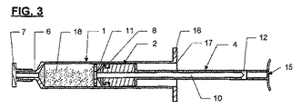
デバイスの第1の例示的な実施例を、図1から図5、とりわけ図2を参照して説明する。デバイス5は、シリンジ・ハウジング1と、ピストン2と、混合アセンブリ3と、プランジャ・ユニット4とを含む。出口又は入口6は、それぞれ、これ以降シリンジ1の出口と呼ばれ、輸送中にクロージャ7を備える。出口6の寸法は、例えば、ルアー・ロック・システムに従った標準である。
A first exemplary embodiment of the device will be described with reference to FIGS. 1 to 5, in particular FIG.
ピストン2は、シリンジ・ハウジング1に対してその円周を、及び混合ロッド10に対してその通路9の両方を密封する密封手段8を備える。混合ロッド10の出口側の端部には、混合ディスク11が配置され、そのもう一方の端部には、連接12を介してプランジャ・ユニット4が取り付けられる。
The
本実施例では、プランジャ・ユニット4は、プランジャ・ロッド13の一方の端部に、スナップ凹部14を有するフランジを備え、スナップ凹部14は、混合ロッド10をつかむようにした寸法にされている。プランジャ・ロッド13のもう一方の端部には、指置き付きのハンドル15が設けられ、指置き付きハンドル15は、混合物が分配されている間、シリンジ・ハウジング1の保持フランジ16と協働する。ピストンがシリンジ・ハウジングから引き抜かれるのを防ぐために、ハウジングの端部には、ピストン・ストップ17が設けられている。
In this embodiment, the plunger unit 4 comprises a flange having a snap recess 14 at one end of the plunger rod 13, and the
図3の断面図では、クロージャ7の取外し後に、混合アセンブリ3が、及びそれによりピストン2も、プランジャ・ユニット4によって後退することができるように、シリンジ・ハウジングが、成分、例えば粉末18、又は成分混合物である程度まで満たされ、それにより、液体がシリンジ・ハウジング中に引き込まれる、又は注入されることを可能にするのが見られる。ピストンの密封手段8は、混合物が、シリンジ・ハウジングのもう一方の側から出て行く可能性があるのを防ぐ。
In the cross-sectional view of FIG. 3, after removal of the
図4.1から図4.4、及び図5は、成分が分配され得る前に、成分を引き込み、混合する際の異なる動作段階を示す。図4.1は、プランジャ・ユニット4と共に、満たされた状態、すなわち後退位置にあるピストン2を示し、プランジャ・ロッドは、そのスナップ凹部14を備えるフランジによって混合ロッド10に係合されて、完全に後退している。図4.2の位置では、ピストンには作用せずに、混合ロッドを移動して回転することができるように、プランジャ・ロッドが90度旋回している。
Figures 4.1 to 4.4, and 5 show the different stages of operation in drawing and mixing the components before they can be dispensed. FIG. 4.1 shows the
この長手方向移動、及び同時に行われる回転運動を、図4.3に図示し、ねじれた矢印19によって表す。図4.2及び図4.3では、この操作に先立ってクロージャが取り付けられていることが更に見られる。図4.4の表示では、混合操作が完了しており、混合ロッド10が、そのスナップ凹部を備えるフランジを介してピストンに作用することができるように、プランジャ・ロッドは90度旋回して元に戻され、混合ロッド10にカチッとはまる。続いて、材料を分配するために、指置きに圧力をかけることによって、プランジャ・ユニット、ピストン、及び混合アセンブリが出口方向へ押される。図5では、混合操作を再び断面図に図示し、ねじれた矢印19によって表す。当然ながら、混合物26の分配に先立って、クロージャ7が取り外される。
This longitudinal movement and simultaneous rotational movement are illustrated in FIG. 4.3 and are represented by
図6は、プランジャ・ユニット4の実施例の変形例を示し、ここでは、デバイス20の指置き付きハンドル15が、混合ロッド10に配置され、プランジャ・ユニット21は、ヒンジ22を介してハンドルに連結された連節部品の形態である。このプランジャ・ユニット21の機能は、前述の実例におけるのと同じであり、すなわち、混合操作のために、プランジャ・ユニット21が図7の位置に持ってこられ、液体を引き込む、又は混合物を放出するために、プランジャ・ユニットが混合ロッド10にカチッとはまり、この実施例の変形例のプランジャ・ロッドは、混合ロッド10に対応する溝形断面の形状である。
FIG. 6 shows a variant of the embodiment of the plunger unit 4, in which the
Claims (6)
6. The mixing assembly (3) according to any one of claims 1 to 5, characterized in that it comprises a mixing disc (11) arranged at the outlet end of the mixing rod (10). Devices.
Applications Claiming Priority (2)
| Application Number | Priority Date | Filing Date | Title |
|---|---|---|---|
| CH2922008 | 2008-02-28 | ||
| PCT/CH2009/000070 WO2009105905A1 (en) | 2008-02-28 | 2009-02-19 | Single chamber device for drawing in and dispensing components |
Publications (2)
| Publication Number | Publication Date |
|---|---|
| JP2011512911A true JP2011512911A (en) | 2011-04-28 |
| JP2011512911A5 JP2011512911A5 (en) | 2011-12-01 |
Family
ID=39432584
Family Applications (1)
| Application Number | Title | Priority Date | Filing Date |
|---|---|---|---|
| JP2010547932A Pending JP2011512911A (en) | 2008-02-28 | 2009-02-19 | Single chamber device for drawing and dispensing components |
Country Status (6)
| Country | Link |
|---|---|
| US (1) | US8167835B2 (en) |
| EP (1) | EP2244819B1 (en) |
| JP (1) | JP2011512911A (en) |
| CN (1) | CN101939088B (en) |
| AT (1) | ATE528068T1 (en) |
| WO (1) | WO2009105905A1 (en) |
Cited By (1)
| Publication number | Priority date | Publication date | Assignee | Title |
|---|---|---|---|---|
| JP2021528133A (en) * | 2018-06-14 | 2021-10-21 | ヤンセン ファーマシューティカルズ,インコーポレーテッド | Pharmaceutical product preparation devices and methods |
Families Citing this family (21)
| Publication number | Priority date | Publication date | Assignee | Title |
|---|---|---|---|---|
| WO2009105905A1 (en) * | 2008-02-28 | 2009-09-03 | Medmix Systems Ag | Single chamber device for drawing in and dispensing components |
| DK2528548T3 (en) * | 2010-01-25 | 2015-01-26 | Tecres Spa | INTERIOR TO MANUFACTURER AND MANAGING a two-MIXTURE |
| CH702757A1 (en) | 2010-02-22 | 2011-08-31 | Medmix Systems Ag | Syringe-like mixing device with distally option for self mixing element. |
| CH703422A1 (en) | 2010-07-01 | 2012-01-13 | Medmix Systems Ag | Combined mixing and discharge. |
| TWI391156B (en) * | 2010-10-20 | 2013-04-01 | Central Medical Technologies Inc | A mixed irrigation device for orthopedics |
| CH705193A1 (en) | 2011-06-22 | 2012-12-31 | Medmix Systems Ag | Apparatus for bubble poor mixing and dispensing a product. |
| WO2013032263A2 (en) * | 2011-08-31 | 2013-03-07 | Lg Electronics Inc. | Laundry treating apparatus |
| US8833606B2 (en) | 2012-01-03 | 2014-09-16 | Howmedica Osteonics Corporation | Device and method for mixing and applying biomaterials |
| US9204914B2 (en) * | 2012-01-27 | 2015-12-08 | Kyphon Sarl | Cement mixer and bone filler device |
| ES2421545B1 (en) * | 2012-02-01 | 2014-06-25 | Universitat Polit�Cnica De Catalunya | BODY CEMENT DOSAGE AND INJECTION DEVICE |
| DE102012008815B4 (en) * | 2012-05-07 | 2014-03-06 | Heraeus Medical Gmbh | Mixing device for multi-component systems |
| DE102012024710A1 (en) * | 2012-11-07 | 2014-05-08 | Heraeus Medical Gmbh | Device for mixing and discharging a pasty mass |
| WO2014145906A2 (en) | 2013-03-15 | 2014-09-18 | Phd Preventative Health Care And Diagnostics, Inc. | A prefilled medication device, method of making and using the same |
| US9456861B2 (en) * | 2013-06-24 | 2016-10-04 | Nordson Corporation | Dispensing assembly having mixing and plunging assembly, and related methods |
| CN104586497B (en) * | 2015-02-09 | 2016-11-16 | 北京闪星世纪医疗科技有限公司 | Bone cement implantation tool |
| CN104688321B (en) * | 2015-03-12 | 2017-03-01 | 艾科美医疗器械(深圳)有限公司 | Integral type bone cement filling apparatuss with stirring and perfusion functional |
| DE102015116797B4 (en) | 2015-10-02 | 2018-08-23 | Heraeus Medical Gmbh | Apparatus and method for storing and mixing a bone cement |
| US10231846B2 (en) | 2016-08-19 | 2019-03-19 | Stryker European Holdings I, Llc | Bone graft delivery loading assembly |
| US10391517B1 (en) * | 2018-05-30 | 2019-08-27 | Sulzer Mixpac Ag | Dispenser assembly |
| IL278534A (en) * | 2020-11-05 | 2022-06-01 | Dandy Innovations Ltd | A syringe aid device |
| WO2023141664A2 (en) * | 2022-01-06 | 2023-07-27 | Sunil Mehta | A single-use system and method for continuous homogenization or lysis |
Citations (1)
| Publication number | Priority date | Publication date | Assignee | Title |
|---|---|---|---|---|
| US20040122359A1 (en) * | 2002-09-17 | 2004-06-24 | Kyphon Inc. | Apparatus and methods for mixing two components |
Family Cites Families (26)
| Publication number | Priority date | Publication date | Assignee | Title |
|---|---|---|---|---|
| US3195778A (en) * | 1963-09-17 | 1965-07-20 | Alta Engineering Company | Storage and mixing cartridge |
| US3766917A (en) * | 1968-01-26 | 1973-10-23 | West Co | Two compartment ampul syringe |
| US4463875A (en) * | 1982-06-14 | 1984-08-07 | Robert W. Mann | Method and apparatus for preparing and applying a two-component cement |
| US4676655A (en) * | 1985-11-18 | 1987-06-30 | Isidore Handler | Plunger type cartridge mixer for fluent materials |
| US4776704A (en) * | 1986-12-15 | 1988-10-11 | Dentsply Research & Development Corp. | Mixing and dispensing syringe |
| DK0440846T3 (en) * | 1990-02-07 | 1993-07-12 | Vetter & Co Apotheker | Double chamber syringe and application method |
| DK0591152T3 (en) * | 1990-11-02 | 1996-07-22 | Marion Giebel | Infection prevention catheter device |
| US5395325A (en) * | 1993-03-10 | 1995-03-07 | Moreno; Saul | Double chamber disposable syringe |
| US5496284A (en) * | 1994-09-27 | 1996-03-05 | Waldenburg; Ottfried | Dual-chamber syringe & method |
| US5779668A (en) * | 1995-03-29 | 1998-07-14 | Abbott Laboratories | Syringe barrel for lyophilization, reconstitution and administration |
| GB9511169D0 (en) * | 1995-06-02 | 1995-07-26 | Lilly Co Eli | Containers for liquid medicaments |
| US5785683A (en) * | 1995-07-17 | 1998-07-28 | Szapiro; Jaime Luis | Disposable syringe with two variable volume chambers |
| JP4145490B2 (en) * | 1997-10-20 | 2008-09-03 | ピーアールシー−デソト インターナショナル,インコーポレイティド | Manual dispensing syringe for multi-component substances |
| JP4159202B2 (en) * | 1998-12-21 | 2008-10-01 | 日本特殊陶業株式会社 | Calcium phosphate cement kneading apparatus and method for preparing calcium phosphate cement kneaded material |
| EP1090609A1 (en) * | 1999-10-07 | 2001-04-11 | NGK Spark Plug Company Limited | Device and method for preparing calcium phosphate-based cement |
| JP2001112867A (en) * | 1999-10-18 | 2001-04-24 | Terumo Corp | Syringe containing drug |
| ES2307736T3 (en) * | 2001-03-13 | 2008-12-01 | Mdc Investment Holdings, Inc. | SECURITY INJECTOR PRE-FILLED FOR DILUENT. |
| US6821266B2 (en) * | 2002-11-12 | 2004-11-23 | U.S. Technology, Inc. | Syringe |
| US20040173640A1 (en) * | 2003-03-07 | 2004-09-09 | Larry Brandon | Method and apparatus for tinting caulk |
| ITPD20030139A1 (en) * | 2003-06-25 | 2004-12-26 | Bidoia Sas Di Gianfranco Bidoia E C | MIXER AND DISPENSER DEVICE FOR FASTENING PASTE, |
| DE10337789A1 (en) * | 2003-08-14 | 2005-09-15 | 3M Espe Ag | Single dose syringe for a multi-component material |
| ATE322923T1 (en) * | 2003-09-30 | 2006-04-15 | 3M Espe Ag | SYRINGE ARRANGEMENT |
| CA2543299A1 (en) * | 2003-10-24 | 2005-05-06 | Mdc Investment Holdings, Inc. | Dual chamber mixing syringe and method for use |
| US7524103B2 (en) * | 2003-11-18 | 2009-04-28 | Boston Scientific Scimed, Inc. | Apparatus for mixing and dispensing a multi-component bone cement |
| US7905654B1 (en) * | 2006-11-13 | 2011-03-15 | Luis Cordero | Hand held manually operated mixer |
| WO2009105905A1 (en) * | 2008-02-28 | 2009-09-03 | Medmix Systems Ag | Single chamber device for drawing in and dispensing components |
-
2009
- 2009-02-19 WO PCT/CH2009/000070 patent/WO2009105905A1/en active Application Filing
- 2009-02-19 AT AT09714485T patent/ATE528068T1/en not_active IP Right Cessation
- 2009-02-19 EP EP09714485A patent/EP2244819B1/en active Active
- 2009-02-19 CN CN2009801041133A patent/CN101939088B/en active Active
- 2009-02-19 JP JP2010547932A patent/JP2011512911A/en active Pending
- 2009-02-19 US US12/866,885 patent/US8167835B2/en active Active
Patent Citations (1)
| Publication number | Priority date | Publication date | Assignee | Title |
|---|---|---|---|---|
| US20040122359A1 (en) * | 2002-09-17 | 2004-06-24 | Kyphon Inc. | Apparatus and methods for mixing two components |
Cited By (1)
| Publication number | Priority date | Publication date | Assignee | Title |
|---|---|---|---|---|
| JP2021528133A (en) * | 2018-06-14 | 2021-10-21 | ヤンセン ファーマシューティカルズ,インコーポレーテッド | Pharmaceutical product preparation devices and methods |
Also Published As
| Publication number | Publication date |
|---|---|
| EP2244819A1 (en) | 2010-11-03 |
| WO2009105905A1 (en) | 2009-09-03 |
| CN101939088A (en) | 2011-01-05 |
| CN101939088B (en) | 2013-05-08 |
| ATE528068T1 (en) | 2011-10-15 |
| EP2244819B1 (en) | 2011-10-12 |
| US20110004156A1 (en) | 2011-01-06 |
| US8167835B2 (en) | 2012-05-01 |
Similar Documents
| Publication | Publication Date | Title |
|---|---|---|
| JP2011512911A (en) | Single chamber device for drawing and dispensing components | |
| US8608030B2 (en) | Cartridge system with compressed gas cartridge | |
| JP5502800B2 (en) | Cartridge system and delivery tube used in such a cartridge system | |
| US7575131B2 (en) | Multi-component delivery system | |
| US6425499B1 (en) | Fluid product spraying device | |
| US9827030B2 (en) | Cartridge system having connected feed plungers | |
| JP6010095B2 (en) | Multi-component cartridge system having a displaceable closure within the cartridge | |
| EP2361107B1 (en) | Multi-chambered mixing syringe device and methods of use | |
| US20070228076A1 (en) | Single dose dual fluid cartridge for use with hand-held applicators | |
| JP2011512911A5 (en) | ||
| US20110021982A1 (en) | Dispensing device with bypass | |
| US20070051750A1 (en) | Cartridge | |
| JP5960965B2 (en) | Dual dispenser device | |
| EP2934636A1 (en) | Dual chamber mixing syringes and methods of using same | |
| US9061257B2 (en) | Apparatus for mixing and discharging a fluid product and related system | |
| US20180022528A1 (en) | Mixing and Dispensing Device and Method for Preparing and Applying an Adhesive Consisting of at Least Two Components | |
| US11478332B2 (en) | Dental material delivery system |
Legal Events
| Date | Code | Title | Description |
|---|---|---|---|
| A521 | Request for written amendment filed |
Free format text: JAPANESE INTERMEDIATE CODE: A523 Effective date: 20111007 |
|
| A621 | Written request for application examination |
Free format text: JAPANESE INTERMEDIATE CODE: A621 Effective date: 20111007 |
|
| A977 | Report on retrieval |
Free format text: JAPANESE INTERMEDIATE CODE: A971007 Effective date: 20130122 |
|
| A131 | Notification of reasons for refusal |
Free format text: JAPANESE INTERMEDIATE CODE: A131 Effective date: 20130125 |
|
| A02 | Decision of refusal |
Free format text: JAPANESE INTERMEDIATE CODE: A02 Effective date: 20130628 |