CN1509195A - Pre-filled safety diluent injector - Google Patents
Pre-filled safety diluent injector Download PDFInfo
- Publication number
- CN1509195A CN1509195A CNA028098528A CN02809852A CN1509195A CN 1509195 A CN1509195 A CN 1509195A CN A028098528 A CNA028098528 A CN A028098528A CN 02809852 A CN02809852 A CN 02809852A CN 1509195 A CN1509195 A CN 1509195A
- Authority
- CN
- China
- Prior art keywords
- syringe needle
- shell
- chamber
- cylinder
- medical apparatus
- Prior art date
- Legal status (The legal status is an assumption and is not a legal conclusion. Google has not performed a legal analysis and makes no representation as to the accuracy of the status listed.)
- Pending
Links
Images


Classifications
-
- A—HUMAN NECESSITIES
- A61—MEDICAL OR VETERINARY SCIENCE; HYGIENE
- A61M—DEVICES FOR INTRODUCING MEDIA INTO, OR ONTO, THE BODY; DEVICES FOR TRANSDUCING BODY MEDIA OR FOR TAKING MEDIA FROM THE BODY; DEVICES FOR PRODUCING OR ENDING SLEEP OR STUPOR
- A61M5/00—Devices for bringing media into the body in a subcutaneous, intra-vascular or intramuscular way; Accessories therefor, e.g. filling or cleaning devices, arm-rests
- A61M5/178—Syringes
- A61M5/31—Details
- A61M5/32—Needles; Details of needles pertaining to their connection with syringe or hub; Accessories for bringing the needle into, or holding the needle on, the body; Devices for protection of needles
- A61M5/3205—Apparatus for removing or disposing of used needles or syringes, e.g. containers; Means for protection against accidental injuries from used needles
- A61M5/321—Means for protection against accidental injuries by used needles
- A61M5/3243—Means for protection against accidental injuries by used needles being axially-extensible, e.g. protective sleeves coaxially slidable on the syringe barrel
- A61M5/326—Fully automatic sleeve extension, i.e. in which triggering of the sleeve does not require a deliberate action by the user
- A61M2005/3261—Fully automatic sleeve extension, i.e. in which triggering of the sleeve does not require a deliberate action by the user triggered by radial deflection of the anchoring parts between sleeve and syringe barrel, e.g. spreading of sleeve retaining hooks having slanted surfaces by engagement with conically shaped collet of the piston rod during the last portion of the injection stroke of the plunger
-
- A—HUMAN NECESSITIES
- A61—MEDICAL OR VETERINARY SCIENCE; HYGIENE
- A61M—DEVICES FOR INTRODUCING MEDIA INTO, OR ONTO, THE BODY; DEVICES FOR TRANSDUCING BODY MEDIA OR FOR TAKING MEDIA FROM THE BODY; DEVICES FOR PRODUCING OR ENDING SLEEP OR STUPOR
- A61M5/00—Devices for bringing media into the body in a subcutaneous, intra-vascular or intramuscular way; Accessories therefor, e.g. filling or cleaning devices, arm-rests
- A61M5/178—Syringes
- A61M5/28—Syringe ampoules or carpules, i.e. ampoules or carpules provided with a needle
- A61M5/281—Syringe ampoules or carpules, i.e. ampoules or carpules provided with a needle using emptying means to expel or eject media, e.g. pistons, deformation of the ampoule, or telescoping of the ampoule
- A61M5/283—Syringe ampoules or carpules, i.e. ampoules or carpules provided with a needle using emptying means to expel or eject media, e.g. pistons, deformation of the ampoule, or telescoping of the ampoule by telescoping of ampoules or carpules with the syringe body
-
- A—HUMAN NECESSITIES
- A61—MEDICAL OR VETERINARY SCIENCE; HYGIENE
- A61M—DEVICES FOR INTRODUCING MEDIA INTO, OR ONTO, THE BODY; DEVICES FOR TRANSDUCING BODY MEDIA OR FOR TAKING MEDIA FROM THE BODY; DEVICES FOR PRODUCING OR ENDING SLEEP OR STUPOR
- A61M5/00—Devices for bringing media into the body in a subcutaneous, intra-vascular or intramuscular way; Accessories therefor, e.g. filling or cleaning devices, arm-rests
- A61M5/178—Syringes
- A61M5/28—Syringe ampoules or carpules, i.e. ampoules or carpules provided with a needle
- A61M5/284—Syringe ampoules or carpules, i.e. ampoules or carpules provided with a needle comprising means for injection of two or more media, e.g. by mixing
-
- A—HUMAN NECESSITIES
- A61—MEDICAL OR VETERINARY SCIENCE; HYGIENE
- A61M—DEVICES FOR INTRODUCING MEDIA INTO, OR ONTO, THE BODY; DEVICES FOR TRANSDUCING BODY MEDIA OR FOR TAKING MEDIA FROM THE BODY; DEVICES FOR PRODUCING OR ENDING SLEEP OR STUPOR
- A61M5/00—Devices for bringing media into the body in a subcutaneous, intra-vascular or intramuscular way; Accessories therefor, e.g. filling or cleaning devices, arm-rests
- A61M5/178—Syringes
- A61M5/28—Syringe ampoules or carpules, i.e. ampoules or carpules provided with a needle
- A61M5/285—Syringe ampoules or carpules, i.e. ampoules or carpules provided with a needle with sealing means to be broken or opened
- A61M5/286—Syringe ampoules or carpules, i.e. ampoules or carpules provided with a needle with sealing means to be broken or opened upon internal pressure increase, e.g. pierced or burst
-
- A—HUMAN NECESSITIES
- A61—MEDICAL OR VETERINARY SCIENCE; HYGIENE
- A61M—DEVICES FOR INTRODUCING MEDIA INTO, OR ONTO, THE BODY; DEVICES FOR TRANSDUCING BODY MEDIA OR FOR TAKING MEDIA FROM THE BODY; DEVICES FOR PRODUCING OR ENDING SLEEP OR STUPOR
- A61M5/00—Devices for bringing media into the body in a subcutaneous, intra-vascular or intramuscular way; Accessories therefor, e.g. filling or cleaning devices, arm-rests
- A61M5/178—Syringes
- A61M5/31—Details
- A61M5/3129—Syringe barrels
-
- A—HUMAN NECESSITIES
- A61—MEDICAL OR VETERINARY SCIENCE; HYGIENE
- A61M—DEVICES FOR INTRODUCING MEDIA INTO, OR ONTO, THE BODY; DEVICES FOR TRANSDUCING BODY MEDIA OR FOR TAKING MEDIA FROM THE BODY; DEVICES FOR PRODUCING OR ENDING SLEEP OR STUPOR
- A61M5/00—Devices for bringing media into the body in a subcutaneous, intra-vascular or intramuscular way; Accessories therefor, e.g. filling or cleaning devices, arm-rests
- A61M5/178—Syringes
- A61M5/31—Details
- A61M5/315—Pistons; Piston-rods; Guiding, blocking or restricting the movement of the rod or piston; Appliances on the rod for facilitating dosing ; Dosing mechanisms
- A61M5/31501—Means for blocking or restricting the movement of the rod or piston
- A61M5/31505—Integral with the syringe barrel, i.e. connected to the barrel so as to make up a single complete piece or unit
Abstract
A safety needle-bearing device for mixing and injecting medication from a two-chambered cartridge is provided. The device includes a needle that extends through the forward end of a barrel. A two-chambered cartridge is attached to the barrel and contains components of a medication stored separately in the chambers. A plunger in the rearward end of the cartridge can be advanced into the cartridge to combine the separate components and prepare the medication. As the cartridge is advanced forwardly into the barrel, the medication is injected through the needle and into a patient. At the completion of the injection stroke, the cartridge engages a needle retainer to actuate needle retraction. The needle is subsequently retracted to shield the contaminated needle.
Description
Priority application
The application proposes claim to the priority of the U.S. Provisional Application No.60/275568 of submission on March 13 calendar year 2001, and this application is hereby expressly incorporated by reference.
Technical field
The present invention relates to medical apparatus, more particularly, the medical apparatus that relates to has the shell with two chambers, and these two chambers store a kind of composition that separates of medicine, and two kinds of compositions can be mixed, and is expelled in the patient body subsequently.
Background technology
The syringe of pre-filled stores the separated drug composition, and these compositions can be mixed mutually.These syringes are called as " mixing syringe " sometimes, many first kind of composition, a kind of diluent of storage or second compositions in second chamber of storing in a chamber in them.These syringes can store two kinds of compositions dividually before using this syringe, when using this syringe, can mix two kinds of compositions in this syringe, and be expelled in the patient body immediately.
The mixing syringe of pre-filled is favourable for the medicine of many types.Some drugs is as antibiotic, and vitamin and hormone must be proportionately packaged and be stored, in order that prolong shelf life.These medicines may need to store as a kind of powder composition and a kind of diluent, perhaps store as two kinds of solution that separate.The mixing syringe of pre-filled makes medicine can press composition in the time will injecting this medicine always and stores.In addition, the mixing syringe of pre-filled save measure medicinal components and with burden from the mixing diluents of the container that separates.
Although have these advantages, the mixing syringe that has does not earlier have reliable safety feature, can not prevent that the user of syringe from being pricked by syringe needle after injection by accident.Particularly, the injector assembly that has does not earlier provide the mixing syringe of integrally operating with injection needle, this syringe needle can be covered up automatically after finishing injection.
Summary of the invention
Consider foregoing, the invention provides a kind of medical apparatus of pre-filled, be used for mixing a kind of composition that separates of medicine, and medicine is expelled in the patient body.This device comprises the container that is connected to one two chamber on the syringe needle, and such as a shell, this syringe needle is automatically withdrawn after using.After withdrawal, the needle tip of having polluted is encapsulated in this device, prevents from pricked by syringe needle unintentionally.
This device comprises the cylinder of a hollow, and it is round syringe needle, and has a rear end of opening wide usually, and it forms a seat.The shell that comprises a kind of composition one two chamber partly of medicine is suitable for closing with this seated connection.Before using, composition is stored in two shell chambers dividually.In use, a plunger that is arranged in the shell rear end is pushed ahead in the shell, with in a chamber with two kinds of composition combinations, in order that mix.Pressure follow-up on plunger is pushed ahead medicinal mixture, enters in the patient body by syringe needle.
Injection needle can be operated between an extended position and a retracted position.In extended position, the preceding top of syringe needle is stretched out forward by cylinder.At retracted position, preceding top is encapsulated in the cylinder.When syringe needle was in extended position, a biasing member made syringe needle setover towards retracted position.The active force that syringe needle holding device overcomes biasing member remains on extended position to syringe needle releasedly.In the process of injection stroke, shell is disengaged the syringe needle holding device, allows that biasing member advances syringe needle in the cylinder backward.
Description of drawings
Will be expressly understood top to general introduction of the present invention and following detailed description of the preferred embodiment, in the accompanying drawings in conjunction with following accompanying drawing:
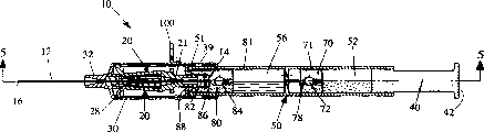
Fig. 1 is a kind of perspective view of shell syringe of pre-filled, and it has the container of one two chamber, the composition part of its storage of pharmaceutical;
Fig. 2 is the exploded perspective illustration of the shell syringe shown in Fig. 1;
Fig. 3 is the enlarged drawing of the locking clamp of the shell syringe shown in Fig. 1;
Fig. 4 is the profile that the shell syringe shown in Fig. 1 is got along line 4-4;
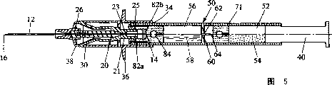
Fig. 5 is the profile that the shell syringe shown in Fig. 4 is got along line 5-5;
Fig. 6 is the profile of the shell syringe shown in Fig. 1, is illustrated in the partially mixed device before of the composition of medicine;
Fig. 7 is the profile of the shell syringe shown in Fig. 1, illustrates and injects blocked shell for prevention and mix device afterwards;
Fig. 8 is the profile of the shell syringe shown in Fig. 1, illustrate with for allowing that the shell that is opened of injection mixes device afterwards;
Fig. 9 is the profile of the shell syringe shown in Fig. 1, and the afterwards and just in time device before the syringe needle withdrawal of injection is shown;
Figure 10 is the profile of the shell syringe shown in Fig. 1, and syringe needle withdrawal device afterwards is shown;
Figure 11 is the part sectioned view that the shell shown in Fig. 1 is penetrated the amplification of device, and anti-interference connection the between shell and cylinder is shown after the syringe needle withdrawal;
Figure 12 is the profile of second embodiment of shell syringe that two chamber pre-filleds of retractable needle are arranged;
Figure 13 is the profile that the device shown in Figure 12 is got along line 13-13;
Figure 14 is a profile of the device shown in Figure 12, is illustrated in the device in the process that pharmaceutical compositions mixes and wherein a kind of pharmaceutical compositions shifts between chamber in the shell;
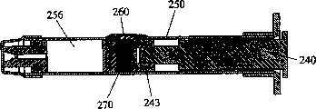
Figure 15 is a profile of the device shown in Figure 12, pharmaceutical compositions is shown mixes device afterwards;
Figure 16 is a profile of the device shown in Figure 12, and syringe needle withdrawal device afterwards is shown;
Figure 17 is the profile of the 3rd embodiment of shell syringe with two chamber pre-filleds of retractable needle;
Figure 18 is the profile of the shell part of the device shown in Figure 17;
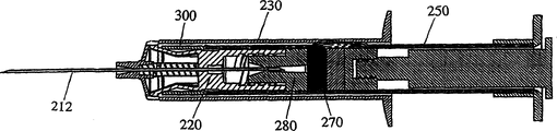
Figure 19 is the profile of the device that does not have shell shown in Figure 17 before using;
Figure 20 is a profile of the shell shown in Figure 18, is illustrated in the device in the blended process of pharmaceutical compositions;
Figure 21 is a profile of the device shown in Figure 18, is illustrated in pharmaceutical compositions and mixes device afterwards;
Figure 22 is a profile of the device shown in Figure 17, and the device of finishing injection is shown;
Figure 23 is a profile of the device shown in Figure 17, and syringe needle withdrawal device afterwards is shown;
Figure 24 is the exploded perspective illustration of the 4th embodiment of shell syringe with two chamber pre-filleds of retractable needle;
Figure 25 is a profile of the device shown in Figure 24;
Figure 26 is a profile of the device shown in Figure 24, pharmaceutical compositions is shown mixes device afterwards;
Figure 27 is a profile of the device shown in Figure 24, and the device of finishing injection is shown;
Figure 28 is a profile of the device shown in Figure 24, and syringe needle withdrawal device afterwards is shown; And
Figure 29 is a profile of the device shown in Figure 24, and syringe needle withdrawal device afterwards is shown.
The specific embodiment
Generally referring to accompanying drawing, particularly referring to Fig. 1-11, an injection device 10 is shown now, it has a syringe needle 12, and this syringe needle has the far-end 16 of a sharpening, is used for being inserted in the patient body.As shown in Figure 4, this injection device 10 has a shell 50 in the attaching, and it has first chamber 52 and second chamber 56.The composition part of these two a kind of medicines of chamber 52,56 pre-filleds will mix them before injection.Shell 50 also comprises a plunger 40, and it can slide in shell.During beginning, in shell 50, plunger 40 reaches are advanced pharmaceutical compositions in second chamber 56 by first chamber 52, two kinds of pharmaceutical compositions are mixed.After composition mixes, plunger advancement is driven forwards shell, so that medicine is expelled in the patient body.After finishing the stroke of injection, the medical worker discharges the pressure from plunger, makes syringe needle 12 can automatically be retracted in the device 10, can not be touched unintentionally to protect contaminated syringe needle 12.
Referring now to Fig. 5-7,, shell 50 comprises first chamber 52 and second chamber 56 that comprises second kind of pharmaceutical compositions 58 that comprise first kind of pharmaceutical compositions 54.A midfeather 60 that comprises a hole 62 was opened two chambers in 52,56 minutes.Sealing member 70 mixed to prevent composition 52 sealings of first chamber after one before using.When back sealing member 70 being pierced through and move forward into plunger 40 in the shell 50, first kind of composition 54 flows in second chamber 56 by hole 62, and it combines with second kind of composition 58 there, forms medicine 59, shown in Fig. 6-7.Follow-up pressure on plunger 40 and shell 50 forces medicine 59 by syringe needle 12 and enter in the patient body.
Referring now to Fig. 4-6,, will the parts of injection device 10 be described in more detail.Cylinder 30 is a substantial cylindrical, and the far-end of cylinder has the nose 32 of a band tapering.This nose 32 has a perforate, and syringe needle 12 passes this hole and stretches, and makes the top 16 of sharpening of syringe needle to be inserted in the patient body.The rear end of this cylinder 30 is opened wide, and forms a columniform seat 34 that is suitable for admitting shell 50.Two flanges 36 that stretch in the horizontal are protruding by cylinder 30, and transversal the longitudinal axis of cylinder forms a pair of finger clamping element that is used for operating means 10.Cylinder 30 also comprises a pair of retaining hole 38 and a pair of pinning window 39 with 20 cooperations of syringe needle holding device, as will be further described below.
As shown in Figure 5, a sleeve 21 is stretched out by the rear end of syringe needle holding device 20.This sleeve 21 is the part of a substantial cylindrical, has a centre bore 23.Syringe needle 12 is located in the centre bore 23 of this sleeve 21, makes the rear end 14 of syringe needle 12 be stretched out by sleeve backward, and the front end 16 of syringe needle is stretched out by sleeve forward.Can syringe needle 12 be installed on the sleeve 21 in one or more modes.For example, can be attached to syringe needle 12 on the sleeve 21 with the binding agent of a kind of binding agent such as a kind of ultraviolet light polymerization.Alternatively, can be molded into syringe needle 12 in the sleeve 21 that forms by plastics.The rear end of sleeve 21 comprises the joint 25 that upwards has barb a week, and this joint is configured to and shell 50 cooperations, shell is connected on the needle hub 21, as below will further discussing.
Syringe needle holding device 20 can move in cylinder 30 in the axial direction, makes the withdrawal of syringe needle become easy.Syringe needle holding device 20 can be formed such as Merlon is molded by a kind of firm high-intensity resin.Before withdrawal, syringe needle holding device 20 remains on a fixed axial location, and medicine 59 is by discharging in the shell 50 simultaneously.After injection, compression spring 28 moves syringe needle holding device 20 and dress syringe needle 12 thereon backward.
Referring now to Fig. 6,, syringe needle holding device 20 comprises a pair of keeping arm 22, and they outwards and are forward stretched diametrically by the far-end of syringe needle holding device 20.In the process of operation, syringe needle holding device 20 can be operated between a latched position and a unlocked position.In latched position, keeping arm 22 engages with retaining hole 38 in cylindrical wall, and keeping syringe needle at a fixed axial location, and the front end 16 of syringe needle 12 is stretched out forward by cylinder 30.More particularly, in latched position, keeping arm 22 engages with cylinder 30, fixes needle hub 21 and syringe needle 12 with the bias power backward that overcomes spring 26.In the position of non-locking, keeping arm 22 is positioned to make needle hub 21 and syringe needle 12 to withdraw backward.More particularly, in the position of non-locking, keeping arm 22 is disengaged with retaining hole 38, makes spring 26 can push pin backward headgear tube 21 and syringe needle 12.
As discussed above, the keeping arm 22 on the syringe needle holding device 20 is also protruding forward, engages with retaining hole 38 in the wall of cylinder 30.The terminal of each arm forms one and keeps projection 24, and this protrusions configuration becomes to project in the retaining hole 38.More particularly, keep projection 24 to engage with the lip that forms by each retaining hole 38 in the wall of cylinder 30.Like this, keep projection 24 to operate as a pair of latch, the power of bias backward that overcomes spring maintains needle hub 21 and syringe needle 12.
Referring to Figure 4 and 5, shell 50 is containers of a substantial cylindrical again, and it can be by the glass of medicine quality such as Pyrex, perhaps by a kind of firm inert plastic such as polyolefin or polyester is molded forms.The midfeather 60 that first and second chambers separate can be made such as polyolefin or polyester by a kind of firm inert plastic.Cylinder or midfeather 60 can be molded as the part of shell 50, perhaps they be bonded on the medial wall of shell.In the process of manufacturing installation 10, fill each chamber with the medicine of scheduled volume.
An elastic preceding sealing member 80 gets up the forward end seal of front chamber 56, can be molded into the sealing part such as polyisoprene by a kind of elastomer of self-packing biological adaptation.This preceding sealing member 80 is roughly cylindrical, has a plurality of axially-spaced circumferential ribs 81.Clearly show that these ribs 81 among Fig. 2, they frictionally and hermetically with the interior bonds of container, realizing, thereby prevent that fluid from being leaked by shell 50 for fluidic sealing.Preceding sealing member 80 also has a front end, and this end can be pierced through in the sharpening top 14 backward of syringe needle 12.After being pierced, the front end of preceding sealing member 80 is realized sealing again round syringe needle 12, in case the fluid stopping body is leaked by shell 50.
Referring now to Fig. 5 and 6,, preceding sealing member 80 has a seat 82, and it is configured to the joint that barb is arranged 25 on needle hub 21 and cooperates.Seat 82 comprises two the recess 82a and the 82b that remove diametrically, they with have the joint 25 of barb to be assembled together.Specifically, there is the joint 25 of barb to engage ordinatedly with preceding sealing member 80 in the primary importance and the second position.
In primary importance, there is the joint 25 of barb to engage, as shown in Figure 5 with the first recess 82a.In this position, shell is attached on the sleeve, but sealing member 80 before does not pierce through the rear end of syringe needle.The pressure that is applied on the plunger 40 makes shell move forward with respect to sleeve, thereby barb is moved to the second position.In the second position, there is the joint 25 of barb to engage, as shown in Figure 6 with the second recess 82b.In this position, preceding sealing member 80 is pierced through in the rear end of syringe needle 12.
Preceding sealing member 80 comprises the chamber 84 of a hollow in its rear end.Like this, between the chamber 84 and the second recess 82b, form the wall that can pierce through 86 in the preceding sealing member 80.As shown in Figure 5, before using, shell 80 is installed in primary importance, and making has the joint 25 of barb to engage with the first recess 82a.In this position, syringe needle 12 does not penetrate the wall 86 that can pierce through.When sleeve 21 was moved on to the second position by primary importance, wall 86 was pierced through in the rear end 14 of syringe needle 12, and is stretched in the chamber 84, as shown in Figure 6.Chamber 84 opens to the inside of second chamber 56 of shell 50, makes that syringe needle is in the state that fluid is communicated with the inside of shell when syringe needle 12 projects in the hollow bulb section 84.After syringe needle 12 penetrated the wall 86 that can pierce through, this wall was realized sealing again round syringe needle, with the tight seal of formation convection cell, and prevented that the medicine in shell 50 from leaking round syringe needle.
In order to prepare to use injection device 10, the medical worker moves forward shell 50 with respect to syringe needle holding device 20, make on the joint 25 that barb is arranged drive before sealing member 80, thereby the joint of barb is engaged with the second recess 82b.Simultaneously, the near-end 14 of syringe needle 12 pierces through the wall 86 that can pierce through, and makes syringe needle be in the state that fluid is communicated with second chamber, as shown in Figure 6.
Be connected preferably a kind of one-way engagement between pro-sealing member 80 and the needle hub 21.In other words, when on the joint 25 that preceding sealing member 80 is installed in barb, shell 50 can have the joint of barb to move forward with respect to this, and still, shell can not have the joint of barb to move backward with respect to this.Like this, can not be easily with shell 50 by removing on the needle hub in the cylinder 30 21, thereby shell for good and all is attached on needle hub and the cylinder basically.
Have barb joint 25 towards after the shoulder and the foursquare of the joint that barb is arranged of band tapering make this unidirectional the connection become easy towards preceding shoulder.Particularly, have barb joint 25 towards after shoulder with first and second radially the side of the band tapering among recess 82a and the 82b cooperate, relatively move to second recess by first recess to allow plunger.Foursquare the opposing by the second recess 82b towards preceding shoulder on the joint 25 that barb is arranged turns back to oppositely moving of the first recess 82a, and this effect stops reverse moving.
Referring now to Fig. 4,, before sealing member 80 be configured to and when the joint 25 of barb moves to the second position by primary importance, stop fluidic ejaculation, in primary importance, the joint 25 that barb arranged with first radially recess 82a engage, and in the second position, the joint that barb arranged with second radially recess 82b engage.Specifically, the front end of preceding sealing member 80 pro-sealing members comprises the head 88 of a gaping or along the flange of circumference.The far-end that opens wide of shell 50 stops with the edge 51 of a crimping, and this edge rests against on the back edge of head 88 of gaping.The external diameter of the head 88 of gaping is bigger than the internal diameter of the far-end that opens wide of shell 50, thereby when initially active force being applied on the plunger 40, sealing member is after 80s before stoping moves up in the shell.Also have, the frictional engagement necessary forces before overcoming between the inwall of the excircle of sealing member 80 and shell 50 is bigger than plunger 25 is moved to the second recess 82b necessary forces by the first recess 82a.Therefore, when active force initially was applied on the plunger 40, preceding sealing member 80 remained on a fixed position with respect to shell 50, and has the joint 25 of barb to be moved to the second position.This restriction of preceding sealing member 80 stoped fluid is flowed out by shell 50 when syringe needle 12 pierces through wall 86.
In the process of store injection device 10, medicine is divided into two compositions that separate that leave in the shell 50, as shown in Figure 5.Specifically, first composition 54 of medicine is stored in the rear chamber 52, and second composition 58 of medicine is stored in the front chamber 56.The midfeather 60 that comprises a hole 62 separates these two chambers with the piercing member 64 that is installed in a hollow in the hole.Hole 62 is presented axially in the center of midfeather 60.In addition, little steam vent 63 is positioned on the midfeather 60 just off-center, and discharging is from the air of the dead space area between midfeather and the mid seal 70.Best, piercing member 64 is made such as rustless steel or treated carbon steel wire by suitable non-corrosive material.When in shell 50 plunger 40 being pushed away forward in the axial direction, first composition 54 in rear chamber 52 enters front chamber 56 by piercing member 64 forward, to mix with second composition 58.
Before using injection device 10, elastic mid seal 70 stops the fluid between first and second chamber to be communicated with, and the sealing part can be formed such as polyisoprene is molded by a kind of elastomer of self-packing biological adaptation.Mid seal 70 is slidably disposed in first chamber 52 when initial, between the piercing member 64 and first composition 54, shown in Fig. 4-5.Mid seal 70 is a substantial cylindrical, a plurality of axially-spaced circumferential ribs 71 is arranged, as clearlying show that among Fig. 2.These ribs 71 frictionally and hermetically engage with the inwall of shell 50, to realize for fluidic tight seal.This tight seal prevents that the fluid in first chamber from entering piercing member 64.Mid seal 70 is also included within a hollow bulb section 72 that forms in the front end of this mid seal, opens wide for first chamber 52 in the rear end of mid seal.A skim 78 is with the front end sealing of mid seal 70, and piercing member 64 can pierce through this film.After piercing through this film 78, realize that between first and second chamber fluid is communicated with, mix mutually with first and second compositions of allowing medicine.
As preceding sealing member 80 and mid seal 70, plunger 40 is a substantial cylindrical, and a plurality of axially-spaced circumferential ribs 41 are preferably arranged.Plunger 40 can be formed such as polyisoprene is molded by a kind of elastomer of self-packing biological adaptation.Alternatively, plunger 40 can be a two-part assembly, in this assembly a columniform elastic sealing element is installed on the firm plastic column stopper rod.Clearly show that these ribs 41 among Fig. 2, they frictionally and hermetically with the interior bonds of shell 50, realized for fluidic tight seal, thereby prevented that fluid from being leaked by the near-end of shell.
After mid seal 70 was pierced, the pressure that is applied on the plunger 40 pushed away first composition 54 forward, by piercing member 64, and entered in second chamber 56, and there, first and second composition then mixes mutually, forms medicine 59.Plunger 40 moves forward with respect to first chamber 52, up to flanged part of thumb pad 42 with till the near-end of shell 50 contacts, as shown in Figure 7.The external diameter of thumb pad 42 is bigger than the internal diameter of shell 50, thereby in case thumb pad 42 contacts with the near-end of shell 50, will stop plunger 40 further to move.Best, equal the distance between the near-end of flanged part of thumb pad 42 and shell 50 in the distance between the rear end of the front end of plunger 40 and mid seal 70.In case thumb pad 42 contacts with the near-end of shell 50, plunger is fixing with respect to shell 50.At this state, limited shell 50 with respect to cylinder 30 reach in the axial direction, as will be described in more detail as follows.
Best, injection device 10 comprises a locking mechanism, is used for preventing discharging by accident before two kinds of compositions are mixed the content in second chamber.In the preferred embodiment shown in Fig. 7, cylinder 30 is included in a locking clamp 100 in the cylindrical wall, to prevent to give off by accident pharmaceutical compositions.The wall of cylinder 30 is included in the slit 104 that a pair of footpath that forms in the plane of longitudinal axis of transversal cylinder makes progress.When locking clamp 100 was inserted through slit 104, this clip prevented that the preceding relatively sealing member 80 of shell 50 from moving forward unintentionally, thereby prevents that pharmaceutical compositions from advancing by syringe needle by accident.Locking clamp 100 is preferably made such as acetal or Merlon by a kind of elastic high strength and high-modulus resin, and it is configured to slit 104 in cylinder 30 and engages releasedly.
Referring to Fig. 1-3, locking clamp 100 is a flat part preferably, and it has the lower limb 101 of a pair of flexibly deflection, and these lower limbs couple together and form a U-shaped.The open end of locking clamp 100 has the edge 102 of band tapering, and they make that when in the sidewall that locking clamp 100 is inserted into cylinder 30, lower limb 101 can be to extrinsic deflection.In addition, locking clamp 100 has a plurality of teeth 103 on the inward flange of lower limb 101, and they are suitable for the edge join with the slit 104 that directly makes progress.
When in the sidewall that locking clamp is inserted into cylinder 30, edge 101 is to extrinsic deflection, makes tooth 103 can leave the edge of the slit 104 that the footpath makes progress.Under outside deflection condition, the elasticity of lower limb 101 is inside diametrically towards they original location bias with lower limb.In case tooth 103 is located in the slit 104, lower limb 101 is diametrically inwardly towards they original location deflections, and engages with the outward flange of syringe needle holding device 20 in cylinder 30 releasedly.In the position of inserting, the blind end of locking clamp 100 is retained in the outside of cylinder 30, as shown in figs. 1 and 4.
After pharmaceutical compositions mutually mixes in shell, locking clamp 100 is removed, making can injectable drug 59, as shown in Figure 8.By on the direction of the longitudinal axis of transversal cylinder, drawing the blind end of clip, locking clamp 100 by removing on the cylinder 30.This direction is marked as " A " in Fig. 1.By drawing this clip by this way, lower limb 101 to extrinsic deflection, makes tooth 103 be separated from the edge of slit 104 by slit 104.
After locking clamp 100 is removed on by cylinder 30,, medicine 59 is expelled in the patient body by shell is pushed ahead in the cylinder.The pressure that is applied on the thumb pad 42 makes plunger 40 and shell 50 travel forward with respect to cylinder 30.Because the joint that barb is arranged 25 among the second recess 82b that is installed in preceding sealing member 80 is arranged, it is motionless that preceding sealing member keeps, and shell 50 is pushed away forward, as shown in Figure 9.Before the head 88 of sealing member 80 and gaping be configured to inside with shell 50 and form and be slidingly matched, make shell to slide on the pro-sealing member.When shell 50 was pushed ahead, mid seal 70 and midfeather 60 moved towards preceding sealing member 80.This makes the volume in second chamber 56 reduce, thereby with in the medicine shift-in syringe needle, makes and inject easily.When finishing injection, midfeather 60 is pressed against on the rear end of preceding sealing member 80, as shown in Figure 9.
Referring now to Fig. 9-10,, will the automatic withdrawal of syringe needle 12 be described.In the axial direction shell 50 is pushed forward to the near-end of cylinder 30, till medicine 59 is discharged fully by second chamber 56.When shell 50 is pushed away forward, make circumferential edges 51 displacements of crimping of shell engage with the keeping arm 22 of syringe needle holding device 20.Best, shell 50 is configured to when making on shell being installed in the joint that barb is arranged 25 that is in the second position, and the fore-and-aft distance between the rear end of preceding sealing member 80 and the midfeather 60 and the circumferential edges 51 and the fore-and-aft distance between the keeping arm 22 of shell are corresponding.Like this, when basically all medicines 59 being discharged by device 10, the edge 51 of shell 50 engages with keeping arm 22.
With after keeping arm 22 engages, shell continues pushing ahead and make keeping arm diametrically to intrinsic deflection in the axial direction, makes to keep projection 24 to move inward, as shown in Figure 9 at the edge 51 of shell 50.In inside position, keep the projection 24 and the retaining hole 38 of cylinder 30 to be disengaged.Like this, shell 50 is as a driver, make shell axially on push ahead the position that syringe needle holding device 20 is moved to a non-locking.In the position of this non-locking, syringe needle holding device 20 no longer is locked in the position of the active force that overcomes spring 26.Be in after the position of non-locking and user be released in pressure on the plunger 40 at syringe needle holding device 20, spring 26 pushes pin 12 backward, till the far-end 16 of the sharpening of syringe needle is encapsulated in the cylinder 30.
As shown in Figure 10, when syringe needle 12 withdrawals, syringe needle, syringe needle holding device 20 and shell 50 move together backward.In the process of withdrawal,, make to keep projection 24 to slide along the medial wall of cylinder with keeping arm 22 outwards biasing diametrically.The active force of spring 26 is enough strong, to overcome the frictional resistance that produces between lead arm 28 and cylinder 30.
Best, injection device 10 comprises a mechanism, the part that is used for limiting withdrawal moving backward.Referring now to Fig. 2,4 and 10,, syringe needle holding device 20 comprises a pair of lead arm 28, they and pair of alignment passage that forms in the inwall of cylinder 30 or groove 31 cooperations.Lead arm 28 can be formed such as Merlon is molded by a kind of firm elastic high-strength resin.Lead arm 28 is stretched out forward by syringe needle holding device 20, and protruding diametrically, engages with collimation groove 31.
Each lead arm 28 comprises the elongated rear of a linearity, and it is preferably roughly parallel with the longitudinal axis of cylinder 30.The longitudinal axis of anterior transversal the cylinder 30 of each lead arm 28 is outwardly-bent, and stretches and enter in one of collimation groove 31.When syringe needle holding device 20 is located in the cylinder, lead arm 28 diametrically by their naturalness to intrinsic deflection.In this position, because the elasticity of lead arm is with the inwall diametrically outwards biasing of lead arm 28 facing to cylinder 30.
Preferably the front end with lead arm 28 is included in the collimation groove 31, to limit the rotation of syringe needle and syringe needle holding device 20 basically in the process of syringe needle withdrawal.This joint guarantees that lead arm aims at locking window 39, makes that lead arm snaps onto when the end of withdrawal to lock in the window.Like this, syringe needle holding device 20 is restricted in the process of syringe needle withdrawal and moves in the axial direction.In the process of withdrawal, the frictional resistance of clothes between the medial wall of the front end of lead arm 28 and cylinder 30 is made every effort to overcome in the expansion of spring 26.
As shown in Figure 4, the elongated rear of the linearity of each lead arm 28 is inwardly spaced apart with the inwall of cylinder 30 diametrically, produces a clearance space between the linear segment of lead arm and cylinder.Best, the spatial minimum thickness diametrically of this gap is bigger than the thickness at the wall of shell 50 or shell edge 51.Like this, when shell 50 being pushed away forward when keeping arm 22 is disengaged, lead arm 28 will can not hinder the reach of shell.
Each collimation groove 31 is substantially parallel with the longitudinal axis of cylinder 30.The rear end that groove 31 is stretched over cylinder has been shown among Fig. 4.Yet, may wish to stop groove in the front of cylinder rear end.Intersect with a locking window 39 that forms in the wall of cylinder 30 at the rear portion of each collimation groove 31.Locking window 39 is suitable for admitting the front end of lead arm 28, as shown in figure 10.Particularly, the front end when each lead arm 28 in the process of syringe needle withdrawal is punctual with 39 pairs corresponding of locking windows, and the outside diametrically bias power of lead arm outwards moves arm, makes front end project in the locking window.Lead arm 28 prevents keeper 22 further axially-movables with locking engaging between the window 39.As a result, limit part being moved further on direction forward or backward of having withdrawn.
Best, injection device 10 comprises a mechanism, and restriction is changed or shell 50 removing by cylinder seat 34.Referring now to Figure 11,, present embodiment comprises an annular lip 35, and this lip is inwardly stretched out diametrically by the medial wall of the seat 34 in the cylinder 30.This lip 35 is suitable for resting against on the edge 51 of the crimping on the shell 50, makes easily by the rear end of cylinder 30 shell to be pulled out.As a result, limit access to the part of having withdrawn, particularly limit access to the syringe needle that has polluted.
Referring now to Fig. 4-10,, will the operation of injection device 10 be described.Before using, syringe needle 12 is located at the position of stretching, extension, makes the far-end 16 of syringe needle be stretched out forward by cylinder 30, as shown in Figure 4.Best, shell 50 conveying arrangements 10 in being contained in cylinder 30, making has the joint 25 of barb to be bonded among the first recess 82a.Alternatively, can with cylinder 30 transport enclosure 50 dividually, thereby before using, must be installed to shell on the cylinder.
Under the condition of shell 50 that assembles and cylinder 30, in the vertical direction maintains device 10, makes far-end 16 points upwards of syringe needle 12.Below being placed on thumb the thumb pad 42 of plunger 40, bearing position maintains device 10 by user.In addition, user is put a finger on each finger clamping element 36, with the operation of control device 10.After the finger of user was held on finger clamping element 36, user applied a slight squeezing pressure on thumb pad 42, traditional syringe of extraordinary image.This squeezing pressure makes shell 50 move forward with respect to cylinder, makes that the joint that barb is arranged 25 on syringe needle holding device 20 engages with the second recess 82b in the pro-sealing member 80, and makes syringe needle 12 pierce through wall 86.When current sealing member 80 was pierced, the air that retains in front chamber 56 gave off by syringe needle 12.
The continuation of plunger 40 reach drives sealing member 70 and moves towards piercing member 64, till piercing member pierces through mid seal, is communicated with fluid between the rear chamber 52,56 thereby be implemented in front chamber.At this moment, can be forward in the shift-in front chamber 56 with first composition 54.On thumb pad 42, exert pressure, up to being pulled to first composition 54 in the front chamber 56 by rear chamber 52 fully and till the front end of plunger touches the rear end of mid seal 70.User shakes injection device 10 subsequently, so that first and second compositions 54,58 in the front chamber 56 are mixed.
In mixed process, locking clamp 100 prevents from shell 50 is pushed ahead in the syringe needle holding device 20.This restriction to shell 50 has prevented from given off the probability of medicine 59 unintentionally by syringe needle 12, and has prevented too early syringe needle withdrawal.In case after medicine 59 suitably mixed, user made and can advance shell 50 forward in cylinder by removing locking clamp 100 on the cylinder 30.At this moment, the initial pressure that is applied on the thumb pad 42 promotes shell forward, and with unnecessary air by discharging in second chamber 56.
Subsequently syringe needle is inserted in the patient body, and depression of plunger 40, pushing ahead shell 50 with respect to cylinder 30 in the axial direction, thereby medicine 9 is expelled in the patient body by shell.When the end of injection stroke, the edge 51 of the crimping on shell 50 engages with keeping arm 22, keeps projection 24 thereby move inward diametrically, so that syringe needle holding device 20 is disengaged, enters the off-position.Though syringe needle holding device 22 is in the position of non-locking, syringe needle 12 can not withdrawn before user is by thumb pad 42 release pressures.Like this, user can keep-up pressure on thumb pad 42, until with syringe needle by till extracting out in the patient body.User subsequently can be by release pressure on the thumb pad 42, makes spring 26 head of can pushing pin backward.Alternatively, user can be by release pressure on the thumb pad 42, and syringe needle 12 still is inserted in the patient body.In case discharge thumb pad 42, spring 26 pushes pin 12 backward, makes the contaminated far-end 16 of syringe needle be encapsulated in the cylinder 30.
Generally referring to Figure 12-16,, show second embodiment of the safe diluent syringe of pre-filled now particularly referring to Figure 12-13.This injection device 110 comprise with above getting in touch the substantially similar part of those parts that first embodiment shown in Fig. 1-11 describes.These parts comprise: the cylinder of the syringe needle of a double ended 112, a substantial cylindrical 130, a compression spring 126 and a syringe needle holding device 120, the bias force that this device overcomes spring maintains syringe needle releasedly, and a locking clamp 200.Syringe needle 112 has the near-end 114 of a sharpening and the far-end 116 of a sharpening.Spring 126 surrounds syringe needle 112, and is compressed in the front end of the cylinder inside facing to cylinder 130.The rear end of spring 126 is bearing on the inside of syringe needle holding device 120, with syringe needle 112 and syringe needle holding device at backward direction upper offset.
Opposite with previous embodiment, the shell 150 that second embodiment adopts have one can the selectivity sealing bypass fluid passage 160, with separately, rather than a midfeather and the sealing member that can pierce through are arranged two kinds of pharmaceutical compositions, as top described about first embodiment.Before using, a mid seal 170 in shell 150 was opened two kinds of pharmaceutical compositions in 154,158 minutes.Before using, mid seal 170 is moved forward, contiguous bypass channel 160, this provides a fluid passage, makes two kinds of pharmaceutical compositions 154,158 to mix.Can be expelled to blended composition in the patient body subsequently.
Referring to Figure 12,13, will the details of shell 150 be described in more detail.This shell is the container of a substantial cylindrical.Preceding sealing member 180 sealings that the front end of shell can be pierced through.The rear end of shell is by a piston 143 sealing, and this piston forms the tight seal of convection cell with the inwall of shell.The centre of pro-sealing member 180 and piston 143, mid seal 170 forms the tight seal of convection cell with the inwall of shell, and shell is divided into two chambers, a front chamber 156, be used for admitting first composition 158, and a rear chamber 152, be used for admitting second composition 154.
Though the fluid passage 160 that illustrates is as the extension of an air bubble-shaped,, the fluid passage can be made other configuration.For example, the fluid passage can be a recess or the axial groove that forms in the inwall of shell 150, and it is outstanding to make the fluid passage can can't help the outer surface of shell.Similarly, the fluid passage can be an annular recesses part that forms in shell inside.
Referring to Figure 12, the device 110 that illustrates is in a kind of " storage " position.In this position, mid seal 170 prevents that two kinds of pharmaceutical compositions from mixing.Therefore, if be ready, the shell 150 of sealing can store the longer time, and can not damage the effect of pharmaceutical compositions.In the position that stores, mid seal 170 is located at the back of fluid passage 160, thereby forms the sealing of fluid tight between the inwall of mid seal and shell round the whole circumference of mid seal.
In the process that injection device 110 stores, medicine is divided into two kinds of compositions that separate, be stored in the shell 150, shown in Figure 12-13.Specifically, first composition 154 of medicine is stored in first chamber 152, and second composition 158 of medicine is stored in second chamber 156.As below will further discussing, best, when filling shell in the manufacture process, in second chamber 156, keep air in certain amount.
Referring now to Figure 14,, will describe and how first kind of pharmaceutical compositions 154 be transferred in second chamber 156.In the axial direction mid seal 170 is pushed away forward, up to it with till aliging in fluid passage 160.Like this, fluid passage 160 provides a bypass channel, makes the composition in rear chamber to be injected front chamber.Because front chamber preferably includes air in certain amount (perhaps other compressible fluid), so can compress the composition in the front chamber, make and can push away mid seal forward, align with fluid passage 169.Alternatively, front chamber can comprise a steam vent, is used for giving off air by front chamber to fluid when transferring in the front chamber by rear chamber.If comprise a steam vent, this steam vent preferably can seal, and leaks with the one-tenth branch that prevents to mix in injection process.
Particularly,, in the axial direction plunger 140 is pushed ahead in the shell 150, to compress first composition 154 facing to the rear end of the mid seal 170 in first chamber 152 in order to be blended in two kinds of compositions in the shell.When the buffer brake on mid seal 170 overcomes frictional resistance between mid seal and the shell 150, will move forward mid seal and enter in the shell.In case mid seal 170 moves with fluid passage 160 and aims at, between the inwall of mid seal and fluid passage, produce a passage, as shown in figure 14.
After the mixing of composition is finished, locking clamp 200 is removed, to allow medicine is expelled in the patient body.Pressure is applied on the shell 150, to give off medicine by second chamber 156.When injection stroke was finished, shell 150 activated syringe needle holding device 120.Pressure on shell 150 will be released, and make syringe needle to withdraw, as shown in figure 16.
Usually referring to Figure 17-23, particularly referring to Figure 17, another embodiment of the safe diluent syringe of pre-filled integrally represents with Reference numeral 210 now.This injection device 210 comprises: the syringe needle of a double ended 212, one are put the cylinder 230 of substantial cylindrical of syringe needle and the shell 250 of a substantial cylindrical.Cylinder 230 also comprises a compression spring 226 and a syringe needle holding device 220, and the bias force that this device overcomes spring maintains syringe needle 212 releasedly.Syringe needle 212 has the near-end 214 of a sharpening and the far-end 216 of a sharpening.Spring 226 is round syringe needle 212, and is compressed in the front end of the cylinder inside facing to cylinder 230.The rear end of spring 226 is bearing on the inside of syringe needle holding device 220, with syringe needle 212 and syringe needle holding device at backward direction upper offset.
In this embodiment, before being installed to shell on the needle hub 221, the transfer of pharmaceutical compositions and being blended in shell 250, carries out.Because in blended process, shell 250 is not connected on the needle assembly, so, syringe needle in the blended process of composition, do not had in the danger of withdrawal unintentionally.As a result, cylinder need not comprise a locking clamp, as in other embodiments.
Referring now to Figure 18-19,, the packing and the dispensing of shell 250 and cylinder 230 make them not assemble.Shell 250 is containers of a substantial cylindrical, and it can be by the glass of medicine quality such as Pyrex, perhaps by a kind of firm inert plastic such as polyolefin or polyester is molded forms.A shell cap 253 is arranged on the far-end of shell 250.Shell 250 is configured to the shell 150 shown in Figure 12-16 similar, and comprises the fluid passage 260 of an air bubble-shaped, and it is protruding by the side of shell.A mid seal 270 is slidably disposed in the shell 250, and shell is divided into first chamber 252 and second chamber 256.In the process of manufacturing installation 210, fill each chamber of shell 250 with the pharmaceutical compositions of scheduled volume.Particularly, with first kind of composition, 254 pre-filleds, first chamber 252, and, with second kind of composition, 258 pre-filleds, second chamber 256.
Referring now to Figure 20,, plunger 240 is slidably disposed in the near-end of shell 250.Plunger 240 is made up of a molded plunger rod 241 and the elastic piston 243 of plastics.When pushing ahead in the shell 250 in the axial direction, compress first composition 254 to plunger 240 facing to the rear end of the mid seal 270 in first chamber 252.When the buffer brake on mid seal 270 overcomes frictional resistance between mid seal and the shell 250, will move forward to mid seal in the shell.In case mid seal 270 moves with fluid passage 260 and aims at, between the inwall of mid seal and fluid passage, produce a passage, mobile to allow first material 254 round mid seal, and enter in second chamber 256, it mixes with second material 258 there.
Again referring to Figure 18, shell 250 the far-end of shell comprise one elastic before sealing member 280.Can be molded into this preceding sealing member 280 such as polyisoprene by a kind of elastomer of self-packing biological adaptation.Should before sealing member 80 be roughly cylindrically, have thick columniform rear end 282 being arranged in the shell and by the front end of the shell front end 284 that reduces of a diameter of projection forward.The internal diameter of the external diameter of rear end 282 and shell 250 is similar.In addition, rear end 282 has a plurality of axially-spaced circumferential ribs 286, they frictionally and hermetically with the interior bonds of shell, realizing, thereby prevent that fluid from being leaked by shell for fluidic tight seal.
The front end 284 of preceding sealing member 280 comprises the external screw thread 288 about its circumference.Far-end 284 also comprises a shallow front chamber 290.A narrow hole 292 that is communicated with second chamber, 256 fluids is stretched by the near-end of preceding sealing member 280, and stops in the far-end 284 that diameter reduces.The film 294 that one deck can perversely be worn stops that front chamber 290 is communicated with fluid between the hole 292.
Referring now to Figure 19,, cylinder 230 is a substantial cylindrical, and has the nose 232 of a band tapering on its far-end.This nose 232 has a perforate, and syringe needle 212 passes this hole and stretches.In addition, nose 232 is configured to admits a needle cover 211, and this lid is assemblied on the nose, is being pricked by syringe needle unintentionally preventing when syringe needle 212 is in the position of stretching, extension.The near-end of cylinder 230 opens wide, and forms a columniform seat 234, is suitable for admitting shell 250.Before being connected with shell 250, a columniform cylinder cap 233 seals the opened end portions of cylinder 230 back.Cylinder further comprises a pair of retaining hole 238, and 220 cooperations of they and syringe needle holding device maintaining syringe needle releasedly, and also comprise the pair of locking window, and they and locking projection cooperation are with the position that needle locking is being withdrawn.
Syringe needle holding device 220 comprises the body 221 and a pair of keeping arm 222 of a substantial cylindrical, and these arms are stretched forward by body 221 diametrically.The hole 296 of a substantial cylindrical is arranged in the near-end of body 221 of syringe needle holding device.The inwall in hole 296 comprises female thread 298, and these screw threads are suitable for admitting the external screw thread 288 of the preceding sealing member 280 in the shell 250.
In order to be ready to shell and cylinder, respectively by removing shell cap 253 and cylinder cap 233 on shell 250 and the cylinder 230 so that assemble.The front end that inserts preceding sealing member by the open end that passes cylinder 230 also screws in shell in the hole 296 with the screw thread clockwise direction, and shell 250 is connected on the cylinder 230.Front chamber 290 in the pro-sealing member 280 is preferably coaxial with syringe needle 212, make that shell 250 is installed to the near-end 214 that can make syringe needle on the cylinder 230 enters chamber 290, and pierce through film 294, thereby second chamber of shell is connected with syringe needle 212, be in the fluid connected state, as shown in figure 17.
Referring to Figure 17, shell 250 is connected on the cylinder 230, can medicine be expelled in the patient body by shell is pushed ahead in the cylinder.Before the near-end of sealing member 280 be configured to inside with shell 250 and form and be slidingly matched, make that shell can slide on the pro-sealing member in the process that shell is pushed ahead.When shell 250 was pushed ahead, syringe needle holding device 220 was being pressed in the rear end of preceding sealing member 280, thereby sealing member is motionless before keeping in the process that shell is pushed ahead.At this moment, the mid seal 270 in second chamber, 256 back is moved towards preceding sealing member 280, this makes the volume in second chamber 256 reduce, thereby with in the medicine shift-in syringe needle, makes injection become easy.When finishing injection, the rear end of sealing member 280 before mid seal 270 is pressing, as shown in figure 22.
As among the embodiment in front, by activating syringe needle holding device 220 with syringe needle 212 withdrawals.Specifically, push pin 212 backward, make syringe needle 212 withdrawals by keeping arm 222 and retaining hole 238 in cylindrical wall being disengaged allow spring 226.In order to activate syringe needle holding device 220, apply pressure on the shell 250, shell is marched forward, as shown in figure 22 on the body 221 of syringe needle holding device.In the process that pushes away forward, the far-end of shell 250 engages with a columniform sleeve 300, and this sleeve is round the far-end setting of the body 221 of syringe needle holding device.The internal diameter of releasing sleeve 300 and external diameter preferably equal the internal diameter and the external diameter of shell 250, make the far-end of shell cooperate with telescopic near-end.With before shell 250 engages, the flange 302 restriction releasing sleeves 300 of an inside along the syringe needle holding device in the axial direction move the slip annular fluid passage 223 of this flange on the body 221 of syringe needle holding device in.With after sleeve 300 engages, what shell continued pushes ahead with drive sleeve in the axial direction forward, engages with keeping arm 222 at shell 250.Releasing sleeve 300 makes keeping arm diametrically to intrinsic deflection, throws off and the engaging of retaining hole 238, and allows that spring 226 pushes pin 212 backward, as shown in figure 23.
That crosses as described above is such, the threads engage of sealing member 280 and syringe needle holding device 220 before the 3rd embodiment is included in, rather than the connection that barb is arranged as describing among two embodiment of pro-.Employing is threaded may increase the whole length of syringe needle holding device 220, this so that be increased in the far-end of shell 150 and the distance between the keeping arm 222.For a mode that adapts to this length increase is the length that increases cylinder 230.Yet by combining with releasing sleeve 300, the length of cylinder 230 does not need to increase basically.Releasing sleeve 300 has compensated the length that increases by a prolongation as shell 250.So just no longer need to increase the whole length of device 210.Best, the length of releasing sleeve 300 is a little longer a little than the length of the threads engage between preceding sealing member 280 and the syringe needle holding device 220.
Generally referring to Figure 24-29,, show the 4th embodiment of the safe diluent syringe of pre-filled now particularly referring to Figure 24-25.This injection device 310 comprises: the syringe needle 312 of a double ended, put the cylinder 330 of a substantial cylindrical of syringe needle, and the shell assembly 350 of a substantial cylindrical that is installed in the near-end inside of cylinder.As the embodiment of front, cylinder also comprises a compression spring 326 and a syringe needle holding device 320, and the bias force that this device overcomes spring maintains syringe needle 312 releasedly.Device 310 is also included within the locking clamp 400 of a U-shaped in the cylindrical wall, to prevent giving off medicine by device 310 unintentionally.
In many application, second composition 358 will be a kind of exsiccant powder composition.Exsiccant composition does not require glass container, and can leave in the plastic containers, not the long-time stability of entail dangers to composition.Want cost much effective because make complicated parts than glass by plastic pattern, so, preferably the complexity of the glass part of shell assembly 350 is reduced to minimum.For this purpose, preceding and back cylinder 351,353 is configured to and makes first composition 354 is stored in the cylinder of back fully, and second composition 356 is stored in the preceding cylinder fully.In such device, preceding cylinder 351 comprises more complicated structure, makes that the back cylinder can be a kind of container of simple cup-shaped.Therefore, for those devices of second composition 358 of storing and drying in second chamber 356, can make the preceding cylinder of more complicated by the effective plastic pattern of cost.Best, glass only is used for being molded into back cylinder 353.
As the front illustrated, back cylinder 353 can telescopically be installed on the near-end of preceding cylinder 351 by sleeve.The external diameter at the rear portion of back sealing member is substantially equal to the internal diameter of back cylinder 353, thus frictionally with the interior bonds of back cylinder, and realize the tight seal of convection cell.Back cylinder 353 is suitable for the pressure on the near-end that is applied to the back cylinder is made the slip of response on doing axially on the sealing member 340 of back.
The internal diameter of cylinder 330 is sufficiently big, adapts with the external diameter with back cylinder 353.As a result, with a clearance space outer wall of preceding cylinder 351 inwall with cylinder 330 is separated, as shown in figure 25.A pair of relative longitudinal rib 355 on the outer wall of pro-cylinder is held in preceding cylinder 351 with much bigger cylinder 330 and is the relation of concentric.These longitudinal ribs have been shown among Figure 24.
An elastic back sealing member 340 is set between pro-cylinder 351 and the back cylinder 353.After this sealing member 340 comprises the end 342 that a diameter reduces, and is arranged in the open proximal end of preceding cylinder 351 this end sections.Back sealing member 340 also comprises a flanged end 344, and this end is arranged in the cylinder 353 of back.The end 342 that diameter reduces and flanged end 344 frictionally and hermetically respectively with the interior bonds of preceding cylinder 352 and back cylinder 354.This joint provides the tight seal with the convection cell of the inside of two cylinders, allows that simultaneously back sealing member 340 can move with respect to any one cylinder.The near-end restriction back sealing member 340 of preceding cylinder moves forward with respect to preceding cylinder 351, and preceding cylinder is configured to flanged part of back sealing member and engages ordinatedly.
As the front illustrated, preceding cylinder 351 comprised an inwall 360.The rear end of opening wide of these inwall 360 contiguous shells forms a seat, is used for admitting back sealing member 340.This inwall 360 comprises a hole 362 at the center that is installed in wall 360.The piercing member 364 of a hollow is installed in this hole, and this piercing member stretches towards back sealing member 340 backward.In addition, may wish in inwall 360, to provide a steam vent, pierce through the back during sealing member, the air between discharging back sealing member 340 and the inwall when a back cylinder is pushed ahead.
A skim 348 will back sealing members 340 the far-end sealing, this film is configured to and can be pierced part 364 and pierces through.Back sealing member 340 comprises the intermediate section 346 of a hollow, and the near-end by the back sealing member makes it realize being connected of fluids connections with first chamber 352.In case film 348 is pierced, realize a fluid passage by piercing member 364 and back sealing member 340, win chamber and second chamber 352,356 are coupled together, be in the fluid connected state.Can be molded into back sealing member 340 such as polyisoprene by a kind of elastomer of self-packing biological adaptation of high extension.
Present operation with tracing device 310.A slight squeezing action power is applied on the near-end of back cylinder 353, on the pro-cylinder 351 the back cylinder is pushed ahead in the axial direction.This is compressed the composition 354 of winning between the near-end of the sealing of back sealing member 340 and back cylinder 353.Produce buffer brake at continuation applied pressure on the cylinder 353 of back on the sealing member 340 of back, this makes back sealing member move forward in the axial direction, enters in the piercing member 364.At this moment, film 348 is pierced, to produce a fluid passage between first and second chamber 352,356.
Back cylinder 353 is pushed ahead with respect to preceding cylinder 351, first composition 354 from first chamber 352 is pushed in second chamber 356.In case after first composition 354 discharged by first chamber 352 fully, further pressure on the cylinder 353 of back is pushed ahead the rear pillar bulk phase for preceding cylinder 351, till the near-end of the sealing of cylinder afterwards leans against the near-end of back sealing member 340, as shown in figure 26.In this state, agitating device 310 mixes the composition in second chamber 356.In blended process, locking clamp 400 stops moving of shell assembly 350, thereby makes the probability that gives off medicine by accident reduce to minimum.
After composition mixes, locking clamp 400 is removed.Subsequently the shell assembly is moved forward, make the rear end of syringe needle 312 pierce through preceding sealing member 380.By front chamber air is discharged subsequently.Further pressure is applied on the shell assembly 350, medicine being given off by second chamber 356, and by syringe needle 312.When finishing injection stroke, the near-end of shell assembly 350 activates syringe needle holding device 320, as shown in figure 27.Be released in the pressure on the shell assembly 350 subsequently, make syringe needle 312 to withdraw, shown in Figure 28 and 29.
In some cases, may wish partly to store shell with its parts.In other words, rear pillar body 353 and preceding cylinder 351 are thrown off.Before using, back cylinder 353 can be attached on the preceding cylinder 351, and such assembly that combines that uses of crossing as described above.Under these circumstances, the back cylinder 353 that separates can comprise a cap that separates, with the front end capping with it.Similarly, preceding cylinder 351 can comprise a cap that separates, with its rear end capping.The back cylinder 353 that can throw off makes and can store multiple prior pharmaceutical compositions through measuring, and easily realized mixing with multiple combination before using.
Already used title and phrase words and phrases as described use like that, and without limits.In the process of using these nouns and phrase, get rid of shown and an any equivalent of described characteristics or their part without any attempt.Yet should admit, be possible in scope and spirit of the present invention with interior multiple remodeling at the embodiments described herein.For example, above-described embodiment comprises a syringe needle holding device, and it has a pair of transportable diametrically arm, after using in order to make the syringe needle release needle automatically of withdrawing.Yet, can improve these devices by adopting different syringe needle holding devices, these improved syringe needle holding devices can automatically be withdrawn syringe needle after using or can are not automatically syringe needle to be withdrawn.Therefore, the present invention includes and fall into following claims scope with interior any modification.
Claims (41)
1. medical apparatus, it comprises:
Cylinder, it has open proximal end and far-end;
Syringe needle, it has first top of fining away and can and block between the position in extended position operates, in extended position, first top of fining away is stretched out forward by cylinder, blocking the position, first top of fining away is blocked, and contacts with this first top of fining away unintentionally preventing;
Be in the shell that fluid is communicated with syringe needle, it comprises:
First chamber that comprises first kind of material;
Second chamber that comprises second kind of material;
Fluid flow controller between first chamber and second chamber; And
Can be slidingly arranged in the plunger in the shell;
Biasing member, it can apply active force, and this active force can make syringe needle move with respect to cylinder, so that first top of fining away is covered up; And
The syringe needle holding device, it remains on extended position with syringe needle releasedly;
Wherein, in first chamber, promote plunger in the axial direction forward and can promote first kind of material forward,, and enter in second chamber by the fluid flow controller, there, described first kind of material combines with second kind of material, forms a kind of medical science mixture, and plunger and shell continue after mixture is discharged pushes ahead and can activate the syringe needle holding device, so that syringe needle is discharged, therefore, biasing member makes syringe needle move with respect to cylinder, and first top of fining away is covered up.
2. according to the described medical apparatus of claim 1, it is characterized in that this medical apparatus also comprises the syringe needle carrying device that is fixed on the syringe needle.
3. according to the described medical apparatus of claim 1, it is characterized in that syringe needle has second top of fining away in its rear end.
4. according to the described medical apparatus of claim 1, it is characterized in that during pressure on being released in plunger, syringe needle can be withdrawn.
5. according to the described medical apparatus of claim 1, it is characterized in that this medical apparatus also comprises one or more retainers, when syringe needle moves to when blocking the position, stop first top of fining away to continue moving backward, cross the near-end of cylinder.
6. according to the described medical apparatus of claim 1, it is characterized in that plunger is made of the molded plunger rod that forms of plastics that is connected on the elastic sealing element.
7. according to the described medical apparatus of claim 1, it is characterized in that plunger can move with respect to shell, simultaneously first kind of material discharged by first chamber, and when mixture was discharged in by second chamber, plunger was motionless with respect to the shell maintenance.
8. according to the described medical apparatus of claim 1, it is characterized in that second kind of material is a kind of dusty material.
9. according to the described medical apparatus of claim 1, it is characterized in that second kind of material is a kind of fluent material.
10. according to the described medical apparatus of claim 1, it is characterized in that the volume that first kind of material of the volume ratio of second chamber and second kind of material are added up is big.
11., it is characterized in that the fluid flow controller comprises according to the described medical apparatus of claim 1:
Wall between first and second chamber with perforate;
Pass the piercing member of the hollow of perforate setting, it has the end of sharpening, stretches to enter first chamber; And
Pass the fluid flowing passage of piercing member;
Wherein, move shell towards cylinder in the axial direction plunger is moved, till plunger is pierced part and pierces through, produce the passage that passes plunger, this passage is aimed at the fluid flowing passage in piercing member, so that first kind of material can enter in second chamber by plunger.
12., it is characterized in that the fluid flow controller comprises according to the described medical apparatus of claim 1:
Retention device between first and second chamber with perforate;
Pass the piercing member of the hollow of perforate setting, it has the end of sharpening, and stretching, extension enters first chamber;
Pass the fluid flowing passage of piercing member; And
The mid seal that can be in first chamber moves in the axial direction that can pierce through, when being pierced part and piercing through, it realizes the fluid connection between first and second chamber;
Wherein, moving shell towards retention device in the axial direction moves the mid seal that can pierce through, till mid seal is pierced part and pierces through, the passage of mid seal is passed in generation, this passage is aimed at the fluid flowing passage in piercing member, so that first kind of material can enter in second chamber by mid seal.
13., it is characterized in that the fluid flow controller comprises according to the described medical apparatus of claim 1:
Mid seal between first and second chamber, it can move in shell in the axial direction; And
Elongated fluid passage in the sidewall of shell;
Wherein, towards the shell mobile plunger mid seal is moved in the axial direction, aim at, between the inwall of described mid seal and fluid passage, produce passage with the fluid passage, this passage can flow kind of the material of winning around mid seal, enters in second chamber.
14., it is characterized in that shell for good and all is installed on the cylinder basically according to the described medical apparatus of claim 1.
15. according to the described medical apparatus of claim 1, it is characterized in that, shell is included in the circumferential edges of the crimping on the far-end of shell, cylinder comprises the lip that is inwardly stretched out diametrically by the endoporus at the cylinder of the near-end of cylinder, described lip is suitable for the edge join with the crimping of shell, to stop shell to be removed by the rear portion of cylinder after the syringe needle withdrawal.
16., it is characterized in that biasing member comprises the far-end that is located at cylinder and the compression spring between the syringe needle carrying device according to the described medical apparatus of claim 2.
17., it is characterized in that the syringe needle holding device comprises a pair of tip forward according to the described medical apparatus of claim 2, they are outwards stretched diametrically by the syringe needle carrying device, and they are configured to releasedly with window in cylindrical wall and engage.
18. according to the described medical apparatus of claim 2, it is characterized in that, circumference round the syringe needle carrying device is provided with columniform sleeve, it has the external diameter roughly the same with shell, with shell rough alignment in the axial direction, make shell when injection stroke finishes axially on forward propelling sleeve is moved towards the far-end of cylinder, to activate the syringe needle holding device.
19. according to the described medical apparatus of claim 3, it is characterized in that shell also is included in the preceding sealing member on the far-end of shell, this sealing member is configured to and can be pierced through by second top of fining away, so that the syringe needle and second chamber are coupled together, be in the fluid connected state.
20. according to the described medical apparatus of claim 19, it is characterized in that, before piercing through sealing member needed axial action force rate minimum on the plunger in rear chamber in the axial direction the needed minimum axial direction active force of mobile plunger want little or equal.
21., it is characterized in that the far-end of preceding sealing member comprises external screw thread according to the described medical apparatus of claim 19, and the near-end of syringe needle carrying device comprises chamber, the threaded end of sealing member before being suitable for admitting.
22. a medical apparatus, it comprises:
Cylinder, it has open proximal end, far-end and perforate, and cylindrical wall is passed in this perforate, is oriented to the longitudinal axis perpendicular to cylinder;
Syringe needle, it has first top of fining away and can and block between the position in extended position operates, in extended position, first top of fining away is stretched out forward by cylinder, blocking the position, first top of fining away is blocked, and contacts with this first top of fining away unintentionally preventing;
Be in the shell that fluid is communicated with syringe needle, it comprises:
First chamber that comprises first kind of material;
Second chamber that comprises second kind of material;
The fluid flow controller that between first chamber and second chamber, is connected; And
Can be slidingly arranged in the plunger in the shell;
Biasing member, it can apply active force, and this active force can make syringe needle move with respect to cylinder, so that first top of fining away is covered up;
The syringe needle holding device, it remains on extended position with syringe needle releasedly; And
Locking clamp, it can be connected on the cylinder with pulling down;
Wherein, in first chamber, can push away first kind of material forward to the reach plunger in the axial direction, by the fluid flow controller, enter in second chamber, there, described first kind of material combines with second kind of material, form a kind of medical science mixture, and, by removing locking clamp on the cylinder, make plunger and shell to be moved further with respect to cylinder, to discharge mixture, subsequently, continue to push ahead shell in the axial direction the syringe needle holding device is disengaged by second chamber, make biasing member move syringe needle, so that first top of fining away is covered up with respect to cylinder.
23., it is characterized in that this medical apparatus also comprises the syringe needle carrying device that is fixed on the syringe needle according to the described medical apparatus of claim 22.
24., it is characterized in that syringe needle has second top of fining away in its rear end according to the described medical apparatus of claim 22.
25., it is characterized in that during pressure on being released in plunger, syringe needle can be withdrawn according to the described medical apparatus of claim 22.
26. according to the described medical apparatus of claim 22, it is characterized in that, shell is included in the circumferential edges of the crimping on the far-end of shell, cylinder comprises the lip that is inwardly stretched out diametrically by the endoporus at the cylinder of the near-end of cylinder, described lip is suitable for the edge join with the crimping of shell, with after the syringe needle withdrawal, stop shell to be removed by the rear portion of cylinder.
27., it is characterized in that this medical apparatus also comprises one or more retainers according to the described medical apparatus of claim 22, when syringe needle moves to when blocking the position, stop first top of fining away to continue moving backward, cross the near-end of cylinder.
28., it is characterized in that plunger is made of the molded plunger rod that forms of plastics that is connected on the elastic sealing element according to the described medical apparatus of claim 22.
29., it is characterized in that plunger can move with respect to shell according to the described medical apparatus of claim 22, simultaneously first kind of material discharged by first chamber, and when mixture was discharged in by second chamber, plunger kept motionless with respect to shell.
30. according to the described medical apparatus of claim 22, it is characterized in that, locking clamp comprises flat U-shaped dish, it has a plurality of teeth along the edge of inside, described clip be configured to by cylinder slit and the vertical direction of longitudinal axis of cylinder on slide and position between shell and syringe needle holding device, thereby contacting between prevention shell and the syringe needle holding device.
31., it is characterized in that second kind of material is a kind of dusty material according to the described medical apparatus of claim 22.
32., it is characterized in that second kind of material is a kind of fluent material according to the described medical apparatus of claim 22.
33., it is characterized in that the volume that first kind of material of the volume ratio of second chamber and second kind of material are added up is big according to the described medical apparatus of claim 22.
34., it is characterized in that the fluid flow controller comprises according to the described medical apparatus of claim 22:
Retention device between first and second chamber with perforate;
Pass the piercing member of the hollow of perforate setting, it has the end of sharpening, stretches in first chamber;
Pass the fluid flowing passage of piercing member; And
The mid seal that can be in first chamber moves in the axial direction that can pierce through, when being pierced that part is perverse to be worn, it realizes the fluid connection between first and second chamber;
Wherein, plunger moves with piercing member towards the initial mobile mid seal that can pierce through that makes in the axial direction of retention device, pierce through mid seal and produce and pass the passage of mid seal, this passage is aimed at the fluid flowing passage in piercing member, so that first germplasm can enter in second chamber by mid seal.
35., it is characterized in that the fluid flow controller comprises according to the described medical apparatus of claim 22:
Mid seal between first and second chamber, it can move in shell in the axial direction; And
Elongated fluid passage in the sidewall of shell between the far-end of mid seal and shell;
Wherein, towards the shell mobile plunger mid seal is moved in the axial direction, aim at, between the inwall of described mid seal and fluid passage, produce passage with the fluid passage, this passage can flow kind of the material of winning around mid seal, enters in second chamber.
36., it is characterized in that biasing member comprises the far-end that is located at cylinder and the compression spring between the syringe needle carrying device according to the described medical apparatus of claim 23.
37. according to the described medical apparatus of claim 23, it is characterized in that, the syringe needle holding device is included in a pair of window and a pair of forward the tip forward in the cylinder, and this tip is outwards stretched diametrically by the syringe needle carrying device, and is configured to releasedly with forward window and engages.
38. according to the described medical apparatus of claim 24, it is characterized in that shell also is included in the preceding sealing member on the far-end of shell, this sealing member is configured to and can be pierced through by second top of fining away, so that the syringe needle and second chamber are coupled together, be in the fluid connected state.
39. according to the described medical apparatus of claim 38, it is characterized in that, before piercing through sealing member needed axial action force rate minimum on the plunger in rear chamber in the axial direction the needed minimum axial direction active force of mobile plunger want little or equal.
40. a medical apparatus, it comprises:
Cylinder, it has open proximal end and far-end;
Syringe needle, it has first top of fining away and can and block between the position in extended position operates, in extended position, first top of fining away is stretched out forward by cylinder, blocking the position, first top of fining away is being covered up, contacting with this first top of fining away unintentionally preventing;
Be in the shell that fluid is communicated with syringe needle, it comprises:
First chamber that comprises first kind of material;
Second chamber that comprises second kind of material;
Fluid flow controller between first chamber and second chamber; And
Biasing member, it can apply active force, and this active force can make syringe needle move with respect to cylinder, so that first top of fining away is covered up; And
The syringe needle holding device, it remains on extended position with syringe needle releasedly; And
Wherein, the fluid flow controller is suitable for keeping first and second kinds of materials separately before using, and is suitable for also allowing before injection that first and second kind material mixes, and wherein, syringe needle is in and blocks the position after using.
41. a method that is used for injectable drug, it comprises the steps:
Injection device is provided, and it has first chamber that comprises first kind of pharmaceutical compositions, comprises second chamber of second kind of pharmaceutical compositions, and syringe needle;
First kind of pharmaceutical compositions transferred to second chamber by first chamber;
Mix first kind and second kind of composition, to form a kind of medicinal mixture;
By in the chamber medicinal mixture being discharged; And
After discharging medicinal fluid, make the syringe needle withdrawal, syringe needle is covered up, prevent to contact with it.
Applications Claiming Priority (2)
| Application Number | Priority Date | Filing Date | Title |
|---|---|---|---|
| US27556801P | 2001-03-13 | 2001-03-13 | |
| US60/275,568 | 2001-03-13 |
Publications (1)
| Publication Number | Publication Date |
|---|---|
| CN1509195A true CN1509195A (en) | 2004-06-30 |
Family
ID=23052867
Family Applications (1)
| Application Number | Title | Priority Date | Filing Date |
|---|---|---|---|
| CNA028098528A Pending CN1509195A (en) | 2001-03-13 | 2002-03-13 | Pre-filled safety diluent injector |
Country Status (11)
| Country | Link |
|---|---|
| US (1) | US6981963B2 (en) |
| EP (1) | EP1377326B1 (en) |
| JP (1) | JP2005508202A (en) |
| CN (1) | CN1509195A (en) |
| AT (1) | ATE399033T1 (en) |
| BR (1) | BR0208068A (en) |
| CA (1) | CA2440889A1 (en) |
| DE (1) | DE60227245D1 (en) |
| ES (1) | ES2307736T3 (en) |
| MX (1) | MXPA03008268A (en) |
| WO (1) | WO2002072171A2 (en) |
Cited By (8)
| Publication number | Priority date | Publication date | Assignee | Title |
|---|---|---|---|---|
| CN103100128A (en) * | 2012-05-14 | 2013-05-15 | 中国人民解放军成都军区总医院 | Compound medicine administration method |
| CN103687580A (en) * | 2011-07-06 | 2014-03-26 | 纳克斯梅德控股公司 | Reconstitution device |
| CN104968384A (en) * | 2012-12-17 | 2015-10-07 | 赛诺菲-安万特德国有限公司 | Drug delivery device |
| CN105878017A (en) * | 2012-07-06 | 2016-08-24 | 纳克斯梅德控股公司 | Redissolution method and redissolution device |
| CN110177588A (en) * | 2016-11-18 | 2019-08-27 | Om有限公司 | Encapsulation and equipment for hybrid medicine substance |
| CN110811906A (en) * | 2019-11-21 | 2020-02-21 | 江苏农牧科技职业学院 | Medical advanced immunization device for pseudorabies of piglets in positive pig farm |
| CN112566607A (en) * | 2018-08-07 | 2021-03-26 | 伊奎希尔德医疗有限公司 | Spacer holder with movable spacer |
| CN114867510A (en) * | 2019-12-11 | 2022-08-05 | 赛诺菲 | Injection device |
Families Citing this family (44)
| Publication number | Priority date | Publication date | Assignee | Title |
|---|---|---|---|---|
| ATE355824T1 (en) * | 2000-01-11 | 2007-03-15 | Roland Bodmeier | IMPLANTATION KIT CONTAINING A CARRIER PHASE AND A SOLVENT |
| JP4112851B2 (en) * | 2001-11-27 | 2008-07-02 | テルモ株式会社 | Two-chamber prefilled syringe |
| FR2842428B1 (en) * | 2002-07-19 | 2004-10-08 | Becton Dickinson France | DEVICE FOR INJECTING A PRODUCT, ESPECIALLY FOR MEDICAL USE |
| US20050096597A1 (en) * | 2003-11-03 | 2005-05-05 | Becton, Dickinson And Company | Safety shield system for a syringe |
| US7497847B2 (en) * | 2003-11-03 | 2009-03-03 | Becton, Dickinson And Company | Safety shield system for a syringe |
| US7344517B2 (en) * | 2004-01-20 | 2008-03-18 | Becton, Dickinson And Company | Syringe having a retractable needle |
| US20050171483A1 (en) * | 2004-02-03 | 2005-08-04 | Dennis Williams | Needle cover extractor |
| WO2005079888A2 (en) * | 2004-02-19 | 2005-09-01 | Aditech Pharma Ab | Delivery device for delivering pyy |
| US8088105B2 (en) * | 2004-03-29 | 2012-01-03 | Fertiligent Ltd. | Syringe pump |
| FR2869533B1 (en) * | 2004-05-03 | 2006-07-28 | Sedat Sa | SYRINGE FOR MEDICAL INTERVENTIONS AND NECESSARY FOR RECONSTITUTION OF EXTEMPORANEOUS SUBSTANCES COMPRISING SUCH A SYRINGE |
| AT500930B1 (en) * | 2004-10-25 | 2007-03-15 | Pharma Consult Ges M B H & Co | METHOD AND DEVICE FOR LYOPHILIZING, RECONSTITUTING AND DISTRIBUTING A RECONSTITUTED ACTIVE SUBSTANCE |
| AU2005312310A1 (en) * | 2004-12-03 | 2006-06-08 | Duoject Medical Systems Inc. | Cartridge, device and method for pharmaceutical storage, mixing and delivery |
| CH699723B1 (en) * | 2005-04-25 | 2010-04-30 | Tecpharma Licensing Ag | A device for administering a fluid product. |
| US7780695B2 (en) * | 2005-06-30 | 2010-08-24 | Codman & Shurtleff, Inc. | Chemically based vascular occlusion device deployment |
| CN100368030C (en) * | 2005-11-30 | 2008-02-13 | 湖南千山制药机械股份有限公司 | Two-chamber prefilled syringe and its prefilling method |
| TW200743500A (en) * | 2006-05-26 | 2007-12-01 | ming-zheng Xu | Disposable syringe |
| CA2574746A1 (en) * | 2007-01-22 | 2008-07-22 | Duoject Medical Systems Inc. | Syringe having venting structure and method for mixing two substances in a syringe |
| US20080221584A1 (en) * | 2007-03-06 | 2008-09-11 | Downer David A | Lens Delivery System |
| WO2008151431A1 (en) * | 2007-06-13 | 2008-12-18 | Duoject Medical Systems Inc. | Device for transferring fluids from a cartridge to a container |
| WO2009105905A1 (en) * | 2008-02-28 | 2009-09-03 | Medmix Systems Ag | Single chamber device for drawing in and dispensing components |
| GB2462811B (en) * | 2008-08-18 | 2012-08-15 | Medical House Ltd | Improved autoinjector |
| JP2012519575A (en) * | 2009-03-09 | 2012-08-30 | パーデュー・リサーチ・ファウンデーション | A compact device for rapidly mixing and delivering a substance to a patient |
| IL197761A0 (en) * | 2009-03-23 | 2009-12-24 | Moshe Zalsman | Capsule for mixing together two flowable materials, and kits including such capsules, particularly useful in dentistry |
| US8998880B2 (en) * | 2009-08-06 | 2015-04-07 | Duoject Medical Systems Inc. | Airless mixing with a by-pass syringe |
| US20120316509A1 (en) * | 2010-02-12 | 2012-12-13 | Medmix Systems Ag | Discharge device having a locking element |
| AU2011231330A1 (en) | 2010-03-25 | 2012-09-20 | New Injection Systems Ltd | Injector |
| CA2742555A1 (en) * | 2011-06-10 | 2012-12-10 | Duoject Medical Systems Inc. | Injection device |
| US8672883B2 (en) | 2011-07-11 | 2014-03-18 | C. Garyen Denning | Fluid delivery device and methods |
| DK2739328T3 (en) | 2011-08-05 | 2018-07-23 | Unl Holdings Llc | DOUBLE CAMERA MIXING DEVICE FOR A SPRAY |
| US9821118B2 (en) | 2011-09-02 | 2017-11-21 | Unl Holdings Llc | Automatic reconstitution for dual chamber syringe |
| CA2854003C (en) | 2011-11-07 | 2020-07-14 | Safety Syringes, Inc. | Contact trigger release needle guard |
| WO2014080020A1 (en) | 2012-11-23 | 2014-05-30 | New Injection Systems Ltd | Auto-injector assembly |
| CA2892088A1 (en) * | 2012-11-30 | 2014-06-05 | Unitract Syringe Pty Ltd | Combination plunger device for a dual chamber mixing syringe |
| DE102012024371A1 (en) * | 2012-12-13 | 2014-06-18 | Schott Ag | Storage device Storage of liquid media, in particular medicines and methods for dispensing liquid media |
| PT3003437T (en) | 2013-06-04 | 2019-10-28 | Unl Holdings Llc | Actuation mechanisms for dual chamber mixing syringes |
| JP6514211B2 (en) | 2013-09-16 | 2019-05-15 | ゾエティス・サービシーズ・エルエルシー | Assembly and related methods for continuous drug delivery |
| US9480465B2 (en) * | 2014-01-06 | 2016-11-01 | Richard Hwang | Organism paracentesis device and method thereof |
| EP2905041A1 (en) * | 2014-02-11 | 2015-08-12 | Sulzer Mixpac AG | Syringe |
| US20170153165A1 (en) * | 2015-11-30 | 2017-06-01 | Chidozie O. Nwadigo | Syringe assembly for withdrawing two separate portions of fluid following a single engagement with fluid port |
| EP3658207A4 (en) * | 2017-07-24 | 2021-04-07 | Noble International, Inc. | Medicament training device with plunger limiting mechanism |
| CN110934745B (en) * | 2019-12-23 | 2022-04-22 | 重庆市潼南区中医院 | Safe and rapid medicine preparation injector |
| CN112791271B (en) * | 2021-01-04 | 2023-07-21 | 达尔塔(南京)智能装备有限公司 | First-aid mask for cyanosis patient for ambulance |
| CN115607446A (en) * | 2022-07-01 | 2023-01-17 | 湛江健力源医疗用品有限公司 | Air pressure balanced center needle type totally enclosed safety dispensing device |
| CN115448471B (en) * | 2022-10-19 | 2023-08-15 | 墨之道(山东)测控设备有限公司 | A accurate dosing device of scale inhibitor for circulating cooling water |
Family Cites Families (48)
| Publication number | Priority date | Publication date | Assignee | Title |
|---|---|---|---|---|
| US34845A (en) * | 1862-04-01 | Improved female supporters | ||
| US3563240A (en) * | 1966-07-20 | 1971-02-16 | Jules Silver | Dual unit syringe |
| US3563373A (en) * | 1967-10-06 | 1971-02-16 | Paul E Paulson | Hypodermic syringe assembly |
| US3570486A (en) * | 1968-10-14 | 1971-03-16 | Horizon Ind Ltd | Mixing syringe |
| US3724460A (en) * | 1968-11-14 | 1973-04-03 | American Home Prod | Disposable cartridge for admixing two components of injectable medicament |
| US3636950A (en) * | 1968-11-14 | 1972-01-25 | American Home Prod | Disposable cartridge for admixing two components of injectable medicament |
| US3659749A (en) * | 1970-04-28 | 1972-05-02 | Boris Schwartz | Intermixing syringe |
| US3785379A (en) * | 1971-08-12 | 1974-01-15 | M Cohen | Syringe for injection of freshly mixed liquid-powder |
| US3911916A (en) * | 1971-10-29 | 1975-10-14 | Peter A Stevens | Sequential injection syringe |
| US3946732A (en) * | 1973-08-08 | 1976-03-30 | Ampoules, Inc. | Two-chamber mixing syringe |
| US4031895A (en) * | 1976-04-05 | 1977-06-28 | Porter Robert E | Syringe assembly package |
| US4055177A (en) * | 1976-05-28 | 1977-10-25 | Cohen Milton J | Hypodermic syringe |
| US4059109A (en) * | 1976-07-27 | 1977-11-22 | Tischlinger Edward A | Mixing and dispensing disposable medicament injector |
| US4122943A (en) * | 1976-10-21 | 1978-10-31 | Jules Silver | Valved two compartment dispensing container |
| US4159066A (en) * | 1977-04-29 | 1979-06-26 | Jules Silver | Package for dispensing a plurality of flowable materials |
| US4171698A (en) * | 1977-08-15 | 1979-10-23 | Abbott Laboratories | Prefilled two-compartment syringe |
| NL180634C (en) * | 1977-12-23 | 1987-04-01 | Duphar Int Res | INJECTION SYRINGE AND NEEDLE HOLDER FOR THIS. |
| US4315570A (en) * | 1979-01-04 | 1982-02-16 | Jules Silver | Two-compartment container with means for dispersing contents of one compartment into the other compartment |
| US4405317A (en) * | 1981-09-30 | 1983-09-20 | The West Company | Syringe assembly |
| US4413991A (en) * | 1982-03-18 | 1983-11-08 | Schmitz John B | Dual dose ampule |
| US4424057A (en) * | 1982-04-01 | 1984-01-03 | House Hugh A | Wet-dry syringe |
| US4581016A (en) * | 1984-02-29 | 1986-04-08 | Gettig Pharmaceutical Instrument Co. | Dual cartridge wet/dry syringe |
| DE3417757C2 (en) * | 1984-05-12 | 1994-11-10 | Lucas Dieter Dr | Hypodermic syringe |
| US4689042A (en) * | 1985-05-20 | 1987-08-25 | Survival Technology, Inc. | Automatic medicament ingredient mixing and injecting apparatus |
| US4861335A (en) * | 1985-07-26 | 1989-08-29 | Duoject Medical Systems Inc. | Syringe |
| US4702737A (en) * | 1986-07-14 | 1987-10-27 | Pizzino Joanne L | Dual dose syringe |
| US4693706A (en) * | 1986-08-11 | 1987-09-15 | Mark L. Anderson | Two compartment mixing syringe |
| US5364369A (en) * | 1987-07-08 | 1994-11-15 | Reynolds David L | Syringe |
| US4883471A (en) * | 1988-08-16 | 1989-11-28 | Braginetz Paul A | Disposable shielded medical syringe |
| DE3916101A1 (en) | 1989-05-17 | 1990-11-22 | Vetter & Co Apotheker | SYRINGE FOR MEDICAL PURPOSES |
| US4979941A (en) * | 1989-12-05 | 1990-12-25 | International Medication Systems, Limited | Device suitable for mixing medication |
| US5114411A (en) * | 1990-11-19 | 1992-05-19 | Habley Medical Technology Corporation | Multi-chamber vial |
| US5360410A (en) * | 1991-01-16 | 1994-11-01 | Senetek Plc | Safety syringe for mixing two-component medicaments |
| US5281198A (en) * | 1992-05-04 | 1994-01-25 | Habley Medical Technology Corporation | Pharmaceutical component-mixing delivery assembly |
| US5531683A (en) * | 1992-08-13 | 1996-07-02 | Science Incorporated | Mixing and delivery syringe assembly |
| DE69330373T2 (en) * | 1992-12-01 | 2002-05-02 | Tetsuro Higashikawa | SYRINGE |
| US5489267A (en) * | 1994-01-03 | 1996-02-06 | Moreno; Saul | Double chamber disposable syringe |
| FR2715071B1 (en) * | 1994-01-17 | 1996-03-01 | Aguettant Lab | Automatic drug injector. |
| US5522804A (en) * | 1994-02-15 | 1996-06-04 | Lynn; Lawrence A. | Aspiration, mixing, and injection syringe |
| IT233201Y1 (en) * | 1994-03-24 | 2000-01-26 | Bracco Spa | TWO-COMPONENT DEVICE FOR THE ADMINISTRATION OF DRUGS |
| EP0692235A1 (en) * | 1994-07-14 | 1996-01-17 | International Medication Systems (U.K.) Ltd. | Mixing & dispensing apparatus |
| US5685846A (en) * | 1995-02-27 | 1997-11-11 | Schott Parenta Systems, Inc. | Dual chamber internal by-pass syringe assembly |
| US5637087A (en) * | 1995-03-22 | 1997-06-10 | Abbott Laboratories | Prefilled, two-constituent syringe |
| JPH08280800A (en) * | 1995-04-12 | 1996-10-29 | Nissho Corp | Prefilled syringe for two-liquid injection |
| EP0793973B1 (en) * | 1996-03-15 | 2002-08-07 | Takeda Chemical Industries, Ltd. | Syringe |
| US5865798A (en) * | 1996-06-28 | 1999-02-02 | Becton Dickinson France, S.A. | Stopper assembly having bypass features for use in a multi-chamber syringe barrel |
| EP1107808A4 (en) | 1998-08-28 | 2004-12-15 | Mdc Invest Holdings Inc | Fluid infusion device with retractable needle |
| JP2002529204A (en) * | 1998-11-13 | 2002-09-10 | エラン・フアルマ・インターナシヨナル・リミテツド | System and method for delivering chemicals |
-
2002
- 2002-03-13 ES ES02715114T patent/ES2307736T3/en not_active Expired - Lifetime
- 2002-03-13 US US10/099,933 patent/US6981963B2/en not_active Expired - Lifetime
- 2002-03-13 EP EP02715114A patent/EP1377326B1/en not_active Expired - Lifetime
- 2002-03-13 JP JP2002571129A patent/JP2005508202A/en active Pending
- 2002-03-13 MX MXPA03008268A patent/MXPA03008268A/en unknown
- 2002-03-13 CA CA002440889A patent/CA2440889A1/en not_active Abandoned
- 2002-03-13 WO PCT/US2002/007712 patent/WO2002072171A2/en active Application Filing
- 2002-03-13 AT AT02715114T patent/ATE399033T1/en not_active IP Right Cessation
- 2002-03-13 DE DE60227245T patent/DE60227245D1/en not_active Expired - Fee Related
- 2002-03-13 CN CNA028098528A patent/CN1509195A/en active Pending
- 2002-03-13 BR BR0208068-0A patent/BR0208068A/en not_active Application Discontinuation
Cited By (10)
| Publication number | Priority date | Publication date | Assignee | Title |
|---|---|---|---|---|
| CN103687580A (en) * | 2011-07-06 | 2014-03-26 | 纳克斯梅德控股公司 | Reconstitution device |
| CN103687580B (en) * | 2011-07-06 | 2016-10-05 | 纳克斯梅德控股公司 | Redissolution method |
| CN103100128A (en) * | 2012-05-14 | 2013-05-15 | 中国人民解放军成都军区总医院 | Compound medicine administration method |
| CN105878017A (en) * | 2012-07-06 | 2016-08-24 | 纳克斯梅德控股公司 | Redissolution method and redissolution device |
| CN104968384A (en) * | 2012-12-17 | 2015-10-07 | 赛诺菲-安万特德国有限公司 | Drug delivery device |
| CN110177588A (en) * | 2016-11-18 | 2019-08-27 | Om有限公司 | Encapsulation and equipment for hybrid medicine substance |
| CN112566607A (en) * | 2018-08-07 | 2021-03-26 | 伊奎希尔德医疗有限公司 | Spacer holder with movable spacer |
| CN110811906A (en) * | 2019-11-21 | 2020-02-21 | 江苏农牧科技职业学院 | Medical advanced immunization device for pseudorabies of piglets in positive pig farm |
| CN110811906B (en) * | 2019-11-21 | 2021-10-15 | 江苏农牧科技职业学院 | Medical advanced immunization device for pseudorabies of piglets in positive pig farm |
| CN114867510A (en) * | 2019-12-11 | 2022-08-05 | 赛诺菲 | Injection device |
Also Published As
| Publication number | Publication date |
|---|---|
| US6981963B2 (en) | 2006-01-03 |
| ES2307736T3 (en) | 2008-12-01 |
| DE60227245D1 (en) | 2008-08-07 |
| EP1377326A4 (en) | 2004-12-15 |
| WO2002072171A3 (en) | 2003-10-30 |
| EP1377326A2 (en) | 2004-01-07 |
| JP2005508202A (en) | 2005-03-31 |
| WO2002072171A2 (en) | 2002-09-19 |
| EP1377326B1 (en) | 2008-06-25 |
| US20020177805A1 (en) | 2002-11-28 |
| CA2440889A1 (en) | 2002-09-19 |
| MXPA03008268A (en) | 2004-10-15 |
| BR0208068A (en) | 2005-04-19 |
| WO2002072171A9 (en) | 2002-10-31 |
| ATE399033T1 (en) | 2008-07-15 |
Similar Documents
| Publication | Publication Date | Title |
|---|---|---|
| CN1509195A (en) | Pre-filled safety diluent injector | |
| JP5491951B2 (en) | Automatic syringe and method of assembling the automatic syringe | |
| US6689101B2 (en) | Medical arrangement | |
| CN104093437B (en) | With the low automatic injector for bouncing back and being used as power | |
| AU2001262829B2 (en) | Medical arrangement | |
| US9233209B2 (en) | Medical injection device | |
| CN1212867C (en) | Needle assisted jet injector | |
| CN1126572C (en) | Pre-filled retractable needle injection ampoules | |
| US8100853B2 (en) | Methodology for drug delivery device with sliding valve | |
| CN102143776B (en) | Medicament delivery device with mixing mechanism | |
| US20030196928A1 (en) | Multi-component ampule | |
| US20030199833A1 (en) | Pre-filed retractable needle injection device | |
| US20050020984A1 (en) | Injector with bypass channel | |
| US8382713B2 (en) | Drug delivery device and methodology | |
| CN1509192A (en) | Pre-filled safety vial injector | |
| US20030199814A1 (en) | Multi-component ampule | |
| CN1382064A (en) | Locking mechainsm for jet injector | |
| CN1466471A (en) | Retractable needle medical device for injecting fluid from a pre-filled cartridge | |
| CN1738657A (en) | Needleless injection device | |
| CA2395902A1 (en) | Dual chamber syringe with a dual function piston | |
| CN88102077A (en) | Automatic Two-chamber Syringe | |
| CN107847688A (en) | Torque spring drives injection device | |
| CN104768596A (en) | Drug delivery device with shield operated needle actuator | |
| AU2003204787B2 (en) | Pre-filled retractable needle injection device | |
| CN1207065C (en) | Needleless syringe with prefilled cartridge |
Legal Events
| Date | Code | Title | Description |
|---|---|---|---|
| C06 | Publication | ||
| PB01 | Publication | ||
| C10 | Entry into substantive examination | ||
| SE01 | Entry into force of request for substantive examination | ||
| C02 | Deemed withdrawal of patent application after publication (patent law 2001) | ||
| WD01 | Invention patent application deemed withdrawn after publication |