JP2005339768A - Magnetic recording system using three-layer laminated medium having improved signal-to-noise ratio - Google Patents
Magnetic recording system using three-layer laminated medium having improved signal-to-noise ratio Download PDFInfo
- Publication number
- JP2005339768A JP2005339768A JP2005123456A JP2005123456A JP2005339768A JP 2005339768 A JP2005339768 A JP 2005339768A JP 2005123456 A JP2005123456 A JP 2005123456A JP 2005123456 A JP2005123456 A JP 2005123456A JP 2005339768 A JP2005339768 A JP 2005339768A
- Authority
- JP
- Japan
- Prior art keywords
- layer
- ferromagnetic
- magnetic
- amount
- disk drive
- Prior art date
- Legal status (The legal status is an assumption and is not a legal conclusion. Google has not performed a legal analysis and makes no representation as to the accuracy of the status listed.)
- Pending
Links
- 230000005291 magnetic effect Effects 0.000 title claims abstract description 153
- 239000000956 alloy Substances 0.000 claims abstract description 37
- 229910045601 alloy Inorganic materials 0.000 claims abstract description 36
- 239000000203 mixture Substances 0.000 claims abstract description 15
- 230000005294 ferromagnetic effect Effects 0.000 claims description 48
- 239000011651 chromium Substances 0.000 claims description 30
- 125000006850 spacer group Chemical group 0.000 claims description 19
- 230000008878 coupling Effects 0.000 claims description 15
- 238000010168 coupling process Methods 0.000 claims description 15
- 238000005859 coupling reaction Methods 0.000 claims description 15
- 230000005290 antiferromagnetic effect Effects 0.000 claims description 13
- 230000005415 magnetization Effects 0.000 claims description 12
- 239000000758 substrate Substances 0.000 claims description 11
- 239000010949 copper Substances 0.000 claims description 6
- 239000011253 protective coating Substances 0.000 claims description 6
- 239000010948 rhodium Substances 0.000 claims description 6
- 229910052804 chromium Inorganic materials 0.000 claims description 5
- VYZAMTAEIAYCRO-UHFFFAOYSA-N Chromium Chemical compound [Cr] VYZAMTAEIAYCRO-UHFFFAOYSA-N 0.000 claims description 3
- RYGMFSIKBFXOCR-UHFFFAOYSA-N Copper Chemical compound [Cu] RYGMFSIKBFXOCR-UHFFFAOYSA-N 0.000 claims description 3
- KJTLSVCANCCWHF-UHFFFAOYSA-N Ruthenium Chemical compound [Ru] KJTLSVCANCCWHF-UHFFFAOYSA-N 0.000 claims description 3
- 230000008859 change Effects 0.000 claims description 3
- 229910052802 copper Inorganic materials 0.000 claims description 3
- 229910052741 iridium Inorganic materials 0.000 claims description 3
- GKOZUEZYRPOHIO-UHFFFAOYSA-N iridium atom Chemical compound [Ir] GKOZUEZYRPOHIO-UHFFFAOYSA-N 0.000 claims description 3
- 239000000463 material Substances 0.000 claims description 3
- 229910052703 rhodium Inorganic materials 0.000 claims description 3
- MHOVAHRLVXNVSD-UHFFFAOYSA-N rhodium atom Chemical compound [Rh] MHOVAHRLVXNVSD-UHFFFAOYSA-N 0.000 claims description 3
- 229910052707 ruthenium Inorganic materials 0.000 claims description 3
- 230000005316 antiferromagnetic exchange Effects 0.000 claims description 2
- 230000006698 induction Effects 0.000 claims 1
- 230000001939 inductive effect Effects 0.000 claims 1
- 230000007423 decrease Effects 0.000 abstract description 8
- 230000000694 effects Effects 0.000 abstract description 4
- 238000003475 lamination Methods 0.000 abstract description 2
- 239000010410 layer Substances 0.000 description 134
- 239000010408 film Substances 0.000 description 9
- 239000002245 particle Substances 0.000 description 8
- 230000006872 improvement Effects 0.000 description 3
- 239000010409 thin film Substances 0.000 description 3
- 229910018979 CoPt Inorganic materials 0.000 description 2
- 239000011230 binding agent Substances 0.000 description 2
- 239000002131 composite material Substances 0.000 description 2
- 238000010586 diagram Methods 0.000 description 2
- 229910001004 magnetic alloy Inorganic materials 0.000 description 2
- 239000006249 magnetic particle Substances 0.000 description 2
- 239000002356 single layer Substances 0.000 description 2
- 239000000725 suspension Substances 0.000 description 2
- 230000007704 transition Effects 0.000 description 2
- OKTJSMMVPCPJKN-UHFFFAOYSA-N Carbon Chemical compound [C] OKTJSMMVPCPJKN-UHFFFAOYSA-N 0.000 description 1
- PNEYBMLMFCGWSK-UHFFFAOYSA-N aluminium oxide Inorganic materials [O-2].[O-2].[O-2].[Al+3].[Al+3] PNEYBMLMFCGWSK-UHFFFAOYSA-N 0.000 description 1
- 229910052799 carbon Inorganic materials 0.000 description 1
- 239000011248 coating agent Substances 0.000 description 1
- 238000000576 coating method Methods 0.000 description 1
- 238000007796 conventional method Methods 0.000 description 1
- 230000003247 decreasing effect Effects 0.000 description 1
- 230000000593 degrading effect Effects 0.000 description 1
- 230000003292 diminished effect Effects 0.000 description 1
- 230000005307 ferromagnetism Effects 0.000 description 1
- 230000001788 irregular Effects 0.000 description 1
- 238000001459 lithography Methods 0.000 description 1
- 238000005259 measurement Methods 0.000 description 1
- 229910052751 metal Inorganic materials 0.000 description 1
- 239000002184 metal Substances 0.000 description 1
- 230000009467 reduction Effects 0.000 description 1
Images


Classifications
-
- G—PHYSICS
- G11—INFORMATION STORAGE
- G11B—INFORMATION STORAGE BASED ON RELATIVE MOVEMENT BETWEEN RECORD CARRIER AND TRANSDUCER
- G11B5/00—Recording by magnetisation or demagnetisation of a record carrier; Reproducing by magnetic means; Record carriers therefor
- G11B5/62—Record carriers characterised by the selection of the material
- G11B5/64—Record carriers characterised by the selection of the material comprising only the magnetic material without bonding agent
- G11B5/66—Record carriers characterised by the selection of the material comprising only the magnetic material without bonding agent the record carriers consisting of several layers
- G11B5/676—Record carriers characterised by the selection of the material comprising only the magnetic material without bonding agent the record carriers consisting of several layers having magnetic layers separated by a nonmagnetic layer, e.g. antiferromagnetic layer, Cu layer or coupling layer
- G11B5/678—Record carriers characterised by the selection of the material comprising only the magnetic material without bonding agent the record carriers consisting of several layers having magnetic layers separated by a nonmagnetic layer, e.g. antiferromagnetic layer, Cu layer or coupling layer having three or more magnetic layers
Abstract
Description
本発明は一般的には磁気記録ディスクドライブに係り、より詳しくは固有の媒体信号対ノイズ比 (S0NR) が改良された「積層媒体」磁気記録ディスクを使用する磁気記録ディスクドライブに関する。 The present invention relates generally to magnetic recording disk drives, and more particularly to a magnetic recording disk drive that uses a “laminated medium” magnetic recording disk with improved inherent media signal-to-noise ratio (S 0 NR).
ディスク上の磁気記録媒体が粒状の合金(たとえばCoPt合金)であるような磁気記録ディスクドライブでは、固有媒体ノイズは線記録密度が高くなるに従って増大する。媒体ノイズは記録される磁気遷移の不規則性から生じ、その結果、リードバック信号ピークが不規則にシフトする。媒体ノイズが増大すれば、ビット誤り率が高くなる。したがって、磁気記録ディスクドライブにおける高い面積密度を得るためには、記録媒体の固有媒体ノイズを低下させること、すなわち信号対ノイズ比 (S0NR) を高めることが必要である。 In a magnetic recording disk drive in which the magnetic recording medium on the disk is a granular alloy (for example, a CoPt alloy), the intrinsic medium noise increases as the linear recording density increases. Media noise results from irregularities in the recorded magnetic transitions, resulting in irregular shifts in the readback signal peak. If the medium noise increases, the bit error rate increases. Therefore, in order to obtain a high area density in a magnetic recording disk drive, it is necessary to reduce the inherent medium noise of the recording medium, that is, to increase the signal-to-noise ratio (S 0 NR).
媒体S0NRは、媒体に含まれる単位面積当りの磁性粒子の数をNとする20log (N1/2) に一次比例し、S0NRはdB(デシベル)の単位で表わされる。したがって、Nを増やすことによってS0NRの増大を達成し得る。しかし、記録されている磁化の熱安定性を保つために必要な個々粒子の面積(A)によって、Nは制限される。この制限が生ずるのは、熱による減衰に対する保護に関わるエネルギー項がKUV(式中、KUは異方性であり、Vは個々の磁性粒子の体積である)であるためである。記録されている磁化の熱安定性を保証するには、KUVをある値よりも大きく保たねばならない。単に粒子面積Aを減らしてNを増やすだけでは、Vが小さくなるであろう。なぜなら、V=At(式中tは粒子の高さ、すなわち磁気記録層の厚さである)であるため、Vが小さくなればKUVが小さくなり、熱に対する安定性が低下するからである。 The medium S 0 NR is linearly proportional to 20 log (N 1/2 ) where N is the number of magnetic particles per unit area contained in the medium, and S 0 NR is expressed in units of dB (decibel). Therefore, an increase in S 0 NR can be achieved by increasing N. However, N is limited by the area (A) of the individual particles necessary to maintain the thermal stability of the recorded magnetization. This limitation occurs because the energy term for protection against thermal decay is K U V (where K U is anisotropic and V is the volume of individual magnetic particles). In order to guarantee the thermal stability of the recorded magnetization, K U V must be kept above a certain value. Simply reducing the particle area A and increasing N will reduce V. Because V = At (where t is the height of the particle, that is, the thickness of the magnetic recording layer), if V becomes smaller, K U V becomes smaller and the stability against heat decreases. is there.
この問題を防ぐためのアプローチの一つは、Vが小さくなる割合だけ、異方性KUを増大させることである。しかし、このアプローチは磁気記録ヘッドが発生する利用可能な磁気書込み磁場によって制約される。媒体に書き込む(すなわち記録されている磁化を変化させる)ために必要な磁場は当該媒体の短時間または固有保磁力H0で表わされ、粒子の磁化または磁気モーメントをMとするKU/Mに比例する。したがってKUを増大させればH0も大きくなり、従来の記録ヘッドでは媒体に書き込みを行うことができなくなる可能性がある。それ故、磁気記録ディスクドライブを確実な信頼性で作動させるには、媒体はS0NRを十分に高くし、書込み可能であるためにH0を十分に低くし、熱に対して安定であるためにKUVを十分に高くせねばならない。 One approach to avoid this problem, only the proportion of V is reduced, it is to increase the anisotropy K U. However, this approach is limited by the available magnetic write field generated by the magnetic recording head. The magnetic field required to write to the medium (ie change the recorded magnetization) is represented by the medium's short time or intrinsic coercivity H 0, where K U / M is the particle magnetization or magnetic moment M Is proportional to Therefore, if K U is increased, H 0 also increases, and it may not be possible to write on the medium with a conventional recording head. Therefore, to ensure reliable operation of magnetic recording disk drives, the media has a sufficiently high S 0 NR and is writable so that H 0 is sufficiently low and stable to heat. Therefore, K U V must be high enough.
媒体S0NRの改善は「積層型」媒体を用いることによって達成できる。積層型媒体では、単一磁性層の代わりに、非磁性のスペーサ層によって隔てられ、磁気的に減結合された2個以上の別々の磁性層から成る積層体が用いられる。この発見はS. E. ランバート等(非特許文献1)によってなされ、米国特許(特許文献1)が付与されている。特許文献2には、2個以上の磁性層を持つ積層型媒体において、下部磁性層が反強磁性結合された (AFC) 層であることを特徴とする積層型媒体が記述されている。積層型媒体でS0NRが増大するのは、Nが増加する(たとえば2個の磁性層を用いる時には実質的に2倍となり、3個の磁性層を用いる時には3倍となる)ためである。積層型媒体には、単一の磁性層に使用されたと同一の磁性合金組成物がすべての磁性層に使用されるので、KUの高い磁性合金材料を使用する必要はない。したがってKUは単一層媒体の場合と全く変わらない。また、積層体中のそれぞれの磁性層の厚さが単一磁性層と同一であっても、2個の磁性層に含まれる粒子は非磁性のスペーサ層によって磁気的に減結合されているので、粒子の体積Vは同一のままである。それ故S0NRはKUを低下させることなく高められるのであり、そのため熱安定性が減殺されることはない。
Improvement of the medium S 0 NR can be achieved by using a “stacked” medium. In a laminated medium, instead of a single magnetic layer, a laminate composed of two or more separate magnetic layers separated by a nonmagnetic spacer layer and magnetically decoupled is used. This discovery was made by SE Lambert et al. (Non-Patent Document 1) and has been granted a US patent (Patent Document 1).
しかし、媒体のS0NRを高めるための積層型媒体アプローチでは著しく厚い媒体が必要になる。たとえば、2個の磁性層が使用される場合には磁性層全体の厚さは2倍になる。全体の厚さが増大すると、別の問題、すなわち書き込みが困難になるという問題が起こる。これは、記録ヘッドからの書込み磁場が書込みヘッドから離れるに従って低下し、従って下部磁性層における書込み磁場が上部磁性層におけるそれよりも弱くなるためである。積層型媒体における下部磁性層のH0が書込み磁場よりも大きければ、下部磁性層の磁化を切り換えることはできず、したがって積層型媒体にデータを書き込むことはできない。そのため、2個以上の磁性層を有する使用可能な積層型媒体を製作することは、従来はできなかった。 However, the stacked media approach to increase the S 0 NR of the media requires significantly thicker media. For example, when two magnetic layers are used, the total thickness of the magnetic layer is doubled. As the overall thickness increases, another problem arises: writing becomes difficult. This is because the write magnetic field from the recording head decreases with increasing distance from the write head, and therefore the write magnetic field in the lower magnetic layer is weaker than that in the upper magnetic layer. If H 0 of the lower magnetic layer in the laminated medium is larger than the write magnetic field, the magnetization of the lower magnetic layer cannot be switched, and therefore data cannot be written to the laminated medium. For this reason, it has not been possible to produce a useable laminated medium having two or more magnetic layers.
必要なのは、2個よりも多い磁性層を持ちながら、良好な磁気記録特性を有する積層型媒体である。 What is needed is a stacked medium with good magnetic recording characteristics while having more than two magnetic layers.
本発明は3個以上の磁性層がある積層型磁性構造を有する磁気記録媒体を用いる磁気記録システムにおいて、これら複数の磁性層が書込みヘッドからの距離が増すに従って低下する固有保磁力H0を持つことを特徴とする磁気記録システムである。前記積層構造における下部磁性層は1個の反強磁性結合 (AFC) 層の上部強磁性膜であり、該積層構造における中間層および上層は個々の磁性層である。それぞれの磁性層の中央における書込み磁場はそれぞれの層のH0よりも大きいので、各磁性層の磁化は書込み磁場によって切り換えられ得る。これら磁性層は異なった組成および/または厚さを有し、そのため異なったH0の値を有している。磁性層に使用される合金がCoPtCrB合金である場合、固有保磁力は主としてPtおよび/またはCrの分量を変えることによって変えられる。中間磁性層および上部磁性層に用いられる合金は比較的「高モーメントの」合金であって、S0NRが比較的低いため、通常は磁気記録媒体に使用されないものである。中間磁性層および上部磁性層は、これらの層が書込みヘッドにより近く位置するようにきわめて薄く作り、それによって各磁性層がより強い書込み磁場に露出されるようにすることができる。中間磁性層および上部磁性層が比較的低いS0NRを持っていても、積層の効果によって積層型磁性構造全体のS0NRは改善される。 The present invention is a magnetic recording system using a magnetic recording medium having a laminated magnetic structure with three or more magnetic layers, and the plurality of magnetic layers have an intrinsic coercive force H 0 that decreases as the distance from the write head increases. This is a magnetic recording system. The lower magnetic layer in the laminated structure is an upper ferromagnetic film of one antiferromagnetic coupling (AFC) layer, and the intermediate layer and the upper layer in the laminated structure are individual magnetic layers. Since the write magnetic field at the center of each magnetic layer is larger than H 0 of each layer, the magnetization of each magnetic layer can be switched by the write magnetic field. These magnetic layers have different compositions and / or thicknesses and therefore have different values of H 0 . When the alloy used for the magnetic layer is a CoPtCrB alloy, the intrinsic coercivity can be changed mainly by changing the amount of Pt and / or Cr. The alloys used for the intermediate and upper magnetic layers are relatively “high moment” alloys and are not typically used in magnetic recording media because of their relatively low S 0 NR. The intermediate magnetic layer and the top magnetic layer can be made very thin so that these layers are located closer to the write head, so that each magnetic layer is exposed to a stronger write magnetic field. Even if the intermediate magnetic layer and the upper magnetic layer have a relatively low S 0 NR, the S 0 NR of the entire laminated magnetic structure is improved by the effect of the lamination.
本発明の性質と効果をより良く理解するためには、以下の詳細な説明を添付図面と共に参照されたい。 For a better understanding of the nature and advantages of the present invention, reference should be made to the following detailed description taken together with the accompanying figures.
本発明によれば、S0NRが改善された積層型記録媒体を有する磁気記録システムを提供することができる。 According to the present invention, it is possible to provide a magnetic recording system having a laminated recording medium with improved S 0 NR.
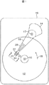
本発明と比較するために、まず、従来技術による磁気記録ディスクおよび磁気記録ハードディスクドライブの構成を説明する。図1は、従来の磁気記録ハードディスクドライブの構成図である。このディスクドライブは、ディスクドライブのハウジングまたはベース16上に支えられた磁気記録ディスク12と回転ボイスコイルモータ (VCM) アクチュエータ14を含んでいる。ディスク12は回転の中心13を持ち、ベース16に取り付けられたスピンドルモータ(図示せず)に駆動されて矢印15の方向に回転する。アクチュエータ14は軸17の周りに回転し、硬質のアクチュエータ・アーム18を含んでいる。サスペンション20は通常は可撓性で、フレクシャ23を含み、アーム18の末端に取り付けられている。ヘッドキャリアまたは空気軸受スライダ22が、フレクシャ23に取り付けられている。磁気記録読取り/書込みヘッド24は、スライダ22の後縁表面25に形成されている。フレクシャ23とサスペンション20があるので、スライダは回転中のディスク12が発生する空気軸受上で「縦揺れ」および「横揺れ」することができる。典型的には、スピンドルモータによって回転する1個のハブに重ねて装着された複数のディスクがあり、それぞれのディスク表面に別々のスライダ及び読取り/書込みヘッドが組み合わされている。
For comparison with the present invention, first, the configuration of a conventional magnetic recording disk and magnetic recording hard disk drive will be described. FIG. 1 is a configuration diagram of a conventional magnetic recording hard disk drive. The disk drive includes a
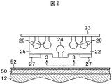
図2はスライダ22の末端と、図1の22線方向でディスク12を切った断面の拡大図である。スライダ22はフレクシャ23に取り付けられており、ディスク12に向いている空気軸受面 (ABS) 27と、通常はABSに垂直な後縁表面25を有する。ABS 27は回転しているディスクからの気流に空気の軸受を発生させ、この空気軸受がスライダ22を、ディスク12の表面にきわめて近接した状態、あるいは殆ど接触に近い状態で支持する。読取り/書込みヘッド24は後縁表面25上に形成されており、後縁表面25上の端子パッド29との電気的接続によってディスクドライブの読取り/書込み電子回路に接続されている。ディスク12は、磁気記録層50と保護被覆52を示すために断面図で示してある。
FIG. 2 is an enlarged view of the end of the
図3は、図2の33線方向から見た図であって、ディスク12から見た読取り/書込みヘッド24の末端を示す。読取り/書込みヘッド24は、スライダ22の後縁表面25上に順次被着され、リソグラフィ法によってパターニングされた複数層の薄膜から成る。書込みヘッドは書込みギャップ30で隔てられた2個の磁性書込み極P1/S2およびP2を含んでいる。磁気抵抗センサすなわち読取りヘッド70は、2個の、典型的にはアルミナで形成されている絶縁ギャップ層G1及びG2の間に位置している。ギャップ層G1およびG2は磁気シールドS1とP1/S2の間に位置しており、P1/S2は書込みヘッド24の第1書込み極としての役割も果たす。
FIG. 3 is a view as seen from the direction of line 33 in FIG. 2 and shows the end of the read / write
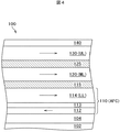
図4は、提案されている積層型磁性構造を有する従来技術の磁気記録ディスク100の断面図であり、該構造はすべてディスク基板102上に形成された3個の磁性層、すなわち反強磁性結合された (AFC) 層110の最上層114である下部強磁性層 (LL)、中間強磁性層 (ML) 120及び上部強磁性層 (UL) 130で構成されている。またディスク100は、1個以上のシード層または下地層から成る下地層構造104、非強磁性のスペーサ層115ならびに125、および在来の保護被覆140も含んでいる。
FIG. 4 is a cross-sectional view of a prior art
AFC層110は、反強磁性結合膜113によって反強磁性結合された2個の強磁性層または強磁性膜(下部膜112及び上部膜114)から構成されており、AFC層110の実効MrtLLは Mrt114−Mrt112 で与えられる。反強磁性結合膜113は、当業者間では周知であるように、膜112および114を反強磁性結合せしめる厚さと組成を持っており、典型的にはルテニウム (Ru)、クロム (Cr)、ロジウム (Rh)、イリジウム (Ir)、銅 (Cu)、およびそれらの合金から成る群から選ばれた材料で形成されている。
The
積層構造の合成Mrtは、MrtUL+MrtML+|(Mrt114−Mrt112)| である。 The composite Mrt of the laminated structure is Mrt UL + Mrt ML + | (Mrt 114 −Mrt 112 ) |.
ディスク100は、次のような構造を持つ。
The
Cr50Ti50 / Ru50Al50 / Cr90Ti10 /
層112 = Co89Cr11 (Mrt112 = 0.13 memu/cm2) / Ru (0.6 nm) /
層114 = Co63Pt12Cr14B11 (Mrt114 = 0.37 memu/cm2) / Ru (1.2 nm) /
ML = Co63Pt12Cr14B11 (MrtML = 0.37 memu/cm2) / Ru (1.2 nm) /
UL = Co63Pt12Cr14B11 (MrtUL = 0.37 memu/cm2) /炭素被覆
Cr50Ti50 / Ru50Al50 / Cr90Ti10 は下地層構造104である。LLおよびMLは1.2 nm Ruの非強磁性スペーサ層115によって磁気的に減結合されており、MLおよびULは 1.2 nm Ruの非強磁性スペーサ層125によって磁気的に減結合されている。先に引用した特許文献2中で提案されているように、層114、120及び130は同一の組成(すなわちCo63Pt12Cr14B11 合金)と厚さを持つ。この組成は手頃な高さの固有保磁力(H0 が8kOe以下)を有する合金であると考えられている。
Cr 50 Ti 50 / Ru 50 Al 50 / Cr 90 Ti 10 /
ML = Co 63 Pt 12 Cr 14 B 11 (Mrt ML = 0.37 memu / cm 2 ) / Ru (1.2 nm) /
UL = Co 63 Pt 12 Cr 14 B 11 (Mrt UL = 0.37 memu / cm 2 ) / carbon coating
Cr 50 Ti 50 / Ru 50 Al 50 / Cr 90 Ti 10 is the
図4中の強磁性層それぞれの磁気モーメントは、矢印で示されている。層130および120の磁気モーメントおよびAFC層110の実効磁気モーメントの向きは、印加された磁場内で飽和された後の残留磁気状態では平行である。Mrt114 はMrt112 よりも大きいものとして(これら2層内に描かれた矢印の相対的な長さによって示されているように表現されているので、層110のモーメントは層114モーメントに平行である。
The magnetic moment of each ferromagnetic layer in FIG. 4 is indicated by an arrow. The orientation of the magnetic moments of
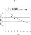
図5は、100 nmの書込みギャップを持つ記録ヘッドについて、正規化磁場(H/HG 、HGは書込みヘッドの書込みギャップにおける磁場)とヘッドの極先端からの垂直距離 y との関係を示す典型的プロファイルである。典型的には、当該磁性層の中央における磁場が、その層に書き込みを行なうために利用できる磁場の測定値として使用される。図4にあるような、提案された3個の磁性層を持つ積層構造における各層の中央が磁場のプロファイル上にマークされており、3個のCoPtCrB合金磁性層それぞれの厚さは10 nm、2個の非磁性スペーサ層それぞれの厚さは1 nm、ヘッドからULの上部までの距離は18 nmであると仮定されている。図5から、磁性層UL、ML及びLLの中央における磁場は、書込みギャップ内に発生する磁場 (HG) のそれぞれ70 %、59 % および50 % であることが見て取れる。LLで利用できる書込み磁場がMLにおけるそれに比べて著しく低下することから見て、従来技術において提案されているもののような3磁性層構造に書き込みを行えるとは考え難い。 Figure 5 shows the relationship between the normalized magnetic field (H / H G , where H G is the magnetic field in the write gap of the write head) and the vertical distance y from the head pole tip for a recording head with a 100 nm write gap. Typical profile. Typically, the magnetic field at the center of the magnetic layer is used as a measurement of the magnetic field that can be used to write to that layer. The center of each layer in the proposed laminated structure with three magnetic layers as shown in FIG. 4 is marked on the magnetic field profile, and each of the three CoPtCrB alloy magnetic layers has a thickness of 10 nm, Each of the nonmagnetic spacer layers is assumed to be 1 nm thick and the distance from the head to the top of the UL is 18 nm. From FIG. 5, it can be seen that the magnetic field at the center of the magnetic layers UL, ML and LL is 70%, 59% and 50% of the magnetic field (H G ) generated in the write gap, respectively. In view of the fact that the write magnetic field that can be used in the LL is significantly lower than that in the ML, it is unlikely that writing can be performed on a three-magnetic layer structure like that proposed in the prior art.
UL、MLおよびLL(層114)の組成と厚さは同一であるから、従来技術におけるこれらの層は同一の固有保磁力を持つであろう。(LLがAFC層110における上部強磁性層114である場合、ヘッドが書き込むことを要するのはこの層だけである。何故なら、反強磁性交換磁場によって下層112の磁化切り換えが引き起こされるからである。したがって、層112の組成がLLのH0に及ぼす影響は無視できる。)これらの層の組成を固有保磁力がほぼ0.70 HG となるように選べば、書込みヘッドはULに書き込みを行うことはできても、LLには書き込むことができないであろう。また、これらの層の組成を固有保磁力がほぼ0.50 HG となるように選べば、書込みヘッドはこれらの層のすべてに書き込みを行うことができるが、積層構造は記録媒体としては受け入れ難いものとなるであろう。それは、上部強磁性層と中間強磁性層では劣悪な性能しか得られず、しかも固有保磁力が約0.70 HG の単一層に比べ、S0NRの改善は微々たるものだからである。
Since the composition and thickness of UL, ML and LL (layer 114) are the same, these layers in the prior art will have the same intrinsic coercivity. (If LL is the upper
次に、本発明の実施例による積層型磁気ディスクの構成及び特性を説明する。上記従来技術における、LLに書き込みを行えない問題に対する解決法の一つは、各層を薄くすることである。たとえば、3個のCoPtCrB合金磁性層それぞれが同一の合金組成で厚さが2 nmであり、2個の非磁性スペーサ層それぞれの厚さが1 nmであれば、磁性層UL、MLおよびLL(層214)の中心における磁場は、それぞれ書込みギャップ内に発生する磁場 (HG) のそれぞれ75 %、72 % および68 % であることが図6から見て取れる。この場合、CoPtCrB合金はほぼ0.68HGの固有保磁力を持つことができ、ヘッドによる書き込みが可能になるであろう。しかしこの解決法では、いずれの層におけるKUV値も許容できないほど低下してしまう結果を招き、これらの層の熱安定性が失われる。したがって記録媒体への使用は許されない。 Next, the configuration and characteristics of the laminated magnetic disk according to the embodiment of the present invention will be described. One of the solutions to the above-described conventional technique that cannot write to the LL is to make each layer thin. For example, if each of the three CoPtCrB alloy magnetic layers has the same alloy composition and a thickness of 2 nm, and each of the two nonmagnetic spacer layers has a thickness of 1 nm, the magnetic layers UL, ML and LL ( It can be seen from FIG. 6 that the magnetic field at the center of layer 214) is 75%, 72% and 68%, respectively, of the magnetic field (H G ) generated in the write gap. In this case, CoPtCrB alloy can have an intrinsic coercive force of approximately 0.68H G, it will permit writing by the head. However, in this solution, also K U V values in any of the layers leads to results which lowers unacceptably thermal stability of the layers is lost. Therefore, use on a recording medium is not permitted.
本発明の実施例では、LL、MLおよびULのそれぞれは異なった組成および/または厚さを持つため、磁性層の保磁力は書込みヘッドからの距離が増大するに従って低下する。図7に実施例の構成を図解説明する。 In embodiments of the present invention, each of LL, ML, and UL has a different composition and / or thickness, so the coercivity of the magnetic layer decreases as the distance from the write head increases. FIG. 7 illustrates the configuration of the embodiment.
図7は、基板202を持ち、3個の磁性層で構成された積層磁性構造を備えた磁気記録ディスク200の断面図である。LLは反強磁性結合された (AFC) 層210の上層214であり、MLは中間強磁性層220であり、ULは上部強磁性層230である。ディスク200には、1個以上のシード層または下地層から成る下地層構造204、非強磁性スペーサ層215および225、及び在来の保護被覆240も含まれている。AFC層210は、反強磁性結合膜213によって反強磁性結合されている強磁性の下層212と強磁性の上層214で構成されている。書込みヘッド250はディスク200の上方に保持され、書込みギャップGによって隔てられた書込み極P1およびP2を含んでいる。書込みヘッドは、ディスクドライブ技術で良く知られているような、空気軸受スライダの後縁表面上に作製されている在来の薄膜型ヘッドである。書込みヘッドはギャップGにおいて磁場HG を発生する。磁場の線は図7中の破線で示されており、書込み磁場の強度は極P1、P2の先端からの距離が増すに従って低下する。矢印はそれぞれの層における磁化の方向を示し、UL、MLおよびLL内の垂線は、これらの層における磁化された領域間の遷移を示す。
FIG. 7 is a cross-sectional view of a
ディスク200では、MLは層ULの合金よりも固有保磁力が低い合金で形成されており、このためMLは記録ヘッドによる書込みが可能となるが、MrtUL が低下することはない。同様にLL(層214)を層MLの合金よりも固有保磁力が低い合金で作ることができ、それによってMrtML を低下させることなくLLの記録ヘッドによる書き込みが可能になる。層LL、MLおよびULに用いられる合金がCoPtCrB合金であれば、固有保磁力は主としてPtの分量を減らすことによって低下する。また、ULおよびMLは比較的「高モーメントの」合金であり、このため所定のMrtUL およびMrtML のための層の厚さを薄くすることができる。モーメントは、主としてCrの分量を減らすことで高められる。したがって、典型的には、MLならびにULはLLよりも低いCr濃度を有するであろう。
In the
上記実施例の適切な積層構造は、次に示すような組成の磁性層を有するであろう。 A suitable laminated structure of the above example will have a magnetic layer with the composition shown below.
UL:Co63Pt(13 - 15)Cr(10 - 16)B(8 - 15)
ML:Co63Pt(12 - 13)Cr(10 - 16)B(8 - 15)
LL(層214):Co63Pt(11 - 12)Cr(10 - 22)B(< 7)
ULおよびMLに用いられる上記の組成は、一般的には在来の磁気記録には不適当である。その理由は、それらが一般に無視できない程の粒子間交換結合を伴う高モーメント合金であって、S0NRを許容できないほど低下させるからである。またMLおよびLLに使用される合金は比較的固有保磁力の低い合金であって、やはりS0NR を許容できないほど低下させる。従来の高性能媒体は「低モーメント」合金であって、固有保磁力が高く、Pt含有量は14 % 以下であり、Cr(>約18原子% )および/またはB(>約10原子% )は比較的高い。粒子が磁気的に減結合されて良好な S0NR が得られるように、CoPt合金にCrおよびBのような分結剤を添加する必要がある。これらの分結剤を多く加えるほど粒子の減結合は著しくなるが、合金のモーメントは低下する。また、高い固有保磁力もS0NR を最大化する。本発明では、MLおよびULに用いられる合金は、S0NR が比較的低い高モーメント合金である。
UL: Co 63 Pt (13 - 15) Cr (10 - 16) B (8 - 15)
ML: Co 63 Pt (12 - 13) Cr (10 - 16) B (8 - 15)
LL (layer 214): Co 63 Pt (11 - 12) Cr (10 - 22) B (<7)
The above compositions used for UL and ML are generally unsuitable for conventional magnetic recording. The reason is that they are high moment alloys with intergranular exchange coupling that is generally not negligible, and lower the S 0 NR unacceptably. Also, the alloys used for ML and LL are alloys with a relatively low intrinsic coercive force, which again reduces S 0 NR unacceptably. Conventional high performance media are “low moment” alloys with high intrinsic coercivity, Pt content of 14% or less, Cr (> about 18 atomic%) and / or B (> about 10 atomic%) Is relatively expensive. It is necessary to add binders such as Cr and B to the CoPt alloy so that the particles are magnetically decoupled and a good S 0 NR is obtained. The more these binders are added, the more decoupled the particles are, but the moment of the alloy is reduced. High intrinsic coercivity also maximizes S 0 NR. In the present invention, the alloys used for ML and UL are high moment alloys with a relatively low S 0 NR.
本発明は、積層構造におけるLLに書き込みができない問題を、S0NR を低下させることなく解決する。複数層のH0 を調節することにより、その時に与えられる合成Mrtの故に、磁性層はヘッドによって書き込み可能となる。このために、LLの固有保磁力は書込みヘッドによってLLの中心に発生する磁場に等しいか、あるいはそれよりも小さくなり、書込みヘッドのLLに対する書き込み能力は大きく変化する。これらの固有保磁力が低い高モーメント合金は、通常はS0NR の低下を示すという理由により選ばれないであろう。しかし本発明では、個々の高モーメント層が在来の合金よりも0.5 dB低ければ、3個の磁性層を有する構造に書き込みを行なえることから得られる効果 (+1.8 dB) のために、全体として著しいS0NRの改善がもたらされるのである。 The present invention solves the problem that writing to the LL in the laminated structure cannot be performed without lowering the S 0 NR. By adjusting the H 0 of multiple layers, the magnetic layer can be written by the head due to the composite Mrt given at that time. For this reason, the intrinsic coercive force of the LL is equal to or smaller than the magnetic field generated at the center of the LL by the write head, and the write ability of the write head to the LL changes greatly. These high moment alloys with low intrinsic coercivity will usually not be selected because they exhibit a decrease in S 0 NR. However, in the present invention, if each individual high moment layer is 0.5 dB lower than the conventional alloy, because of the effect (+1.8 dB) obtained from writing to a structure having three magnetic layers, Overall, there is a significant improvement in S 0 NR.
好ましい実施形態では、LLの固有保磁力H0LL はULの固有保磁力H0UL より少なくとも25 % 低く、MLの固有保磁力H0ML はULの固有保磁力H0UL より少なくとも15 % 低く、ULの固有保磁力H0UL はHGの70 % 以上である。一例として、HG=15 kOeの書込みヘッドが使用されれば、3個の磁性層から成る積層構造は、厚さ10 nmの高モーメントCo62Pt15Cr12B11 で構成されたUL、厚さ10 nmの高モーメントCo63Pt13Cr12B11で構成されたML、厚さ10 nmの低モーメントCo63Pt12Cr18B7 で構成された、LL内の層214、および厚さ1 nmのRuで構成された複数のスペーサ層を持つであろう。この結果、各層の固有保磁力は、おおよそH0UL=10 kOe、H0ML=8 kOe およびH0LL=7 kOeとなり、UL、MLおよびLLの中心における書込み磁場は、それぞれ約10.5 kOe、8.8 kOeおよび7.5 kOeとなるであろう。
In a preferred embodiment, intrinsic coercivity H 0LL of LL is at least 25% than the intrinsic coercive force H 0UL the UL low intrinsic coercivity H 0 ml of ML is at least 15% lower than the intrinsic coercive force H 0UL the UL, specific UL coercivity H 0UL is 70% or more of H G. As an example, if a write head with H G = 15 kOe is used, the stacked structure consisting of three magnetic layers is UL, which consists of a high moment Co 62 Pt 15 Cr 12 B 11 with a thickness of 10 nm. ML composed of high moment Co 63 Pt 13 Cr 12 B 11 with a thickness of 10 nm,
本明細書中で使用される場合、ULおよびLLは、それぞれ積層構造中の最上磁性層および最下磁性層を指す。本発明が3個よりも多い磁性層を持つ積層構造の形で実施される場合、そのような構造は2個以上の中間磁性層 (ML) を持つであろう。 As used herein, UL and LL refer to the uppermost magnetic layer and the lowermost magnetic layer in a laminated structure, respectively. If the present invention is implemented in a stacked structure with more than three magnetic layers, such a structure will have more than one intermediate magnetic layer (ML).
本発明を好ましい実施例について詳細に説明してきたが、当業者には、形態や細部における種々の変更が本発明の精神ならびに範囲から逸脱することなく行なわれ得ることが理解されるであろう。したがって、開示された発明は単に例示的なものであり、添付の特許請求範囲に明記されている範囲以外の制限を受けることはないと考えられるべきである。 Although the invention has been described in detail with reference to preferred embodiments, those skilled in the art will recognize that various changes in form and detail may be made without departing from the spirit and scope of the invention. Accordingly, the disclosed invention is to be considered merely as illustrative and not restrictive beyond the scope specified in the appended claims.
200…磁気記録ディスク、
202…基板、
204…下地層、
210…反強磁性結合(AFC)層、
212…強磁性の下層、
213…反強磁性結合膜、
214…強磁性の上層、
215…非強磁性スペーサ層、
220…中間強磁性層、
225…非強磁性スペーサ層、
230…上部強磁性層、
240…保護被覆、
250…書込みヘッド。
200 ... magnetic recording disk,
202 ... substrate,
204… Underlayer,
210 ... Anti-ferromagnetic coupling (AFC) layer,
212 ... the ferromagnetic underlayer,
213 ... An antiferromagnetic coupling film,
214 ... upper layer of ferromagnetism,
215 ... non-ferromagnetic spacer layer,
220 ... intermediate ferromagnetic layer,
225 ... non-ferromagnetic spacer layer,
230… Upper ferromagnetic layer,
240… Protective coating,
250: Write head.
Claims (27)
書込みギャップによって隔てられた複数の書込み極を持ち、該ギャップにおいて磁場HG を発生してLL、MLおよびULの領域における磁化方向を変化させることができ、前記領域内におけるLL、MLおよびULの磁化方向は平行であり、前記媒体の近傍に保たれ、かつLLの中央における磁場はH0LL よりも大きく、MLの中央における磁場はH0ML よりも大きく、ULの中央における磁場はH0UL よりも大きい誘導書込みヘッドと、
有することを特徴とする磁気記録システム。 Upper ferromagnetic having a unique lower ferromagnetic layer having a coercive force H 0LL (LL), an intermediate ferromagnetic layer having a large intrinsic coercive force H 0 ml than H 0LL (ML), a large intrinsic coercive force H 0UL than H 0 ml A magnetic recording medium comprising a layer (UL), a first non-ferromagnetic spacer layer between LL and ML, and a second non-ferromagnetic spacer layer between ML and UL;
It has a plurality of write poles separated by a write gap and can generate a magnetic field H G in the gap to change the magnetization direction in the LL, ML and UL regions, and the LL, ML and UL in the region. magnetization directions are parallel and kept in the vicinity of the medium, and the magnetic field at the center of the LL is greater than H 0LL, the magnetic field at the center of the ML is greater than H 0 ml, the magnetic field at the center of the UL than H 0UL A large inductive write head,
A magnetic recording system comprising:
該基板上にあり、下部強磁性膜、上部強磁性膜、および前記下部および上部強磁性膜の間に位置して前記下部および上部強磁性膜を反強磁性交換結合する反強磁性結合膜を含み、前記上部強磁性膜が前記基板上の下部強磁性層 (LL) であり、固有保磁力H0LL を有する反強磁性結合(AFC)層と、
LL上にある第1の非強磁性スペーサ層と、
該第1の非強磁性スペーサ層上にあり、H0LL よりも大きな固有保磁力H0ML を有する中間強磁性層 (ML)と、
ML上にある第2の非強磁性スペーサ層と、
該第2の非強磁性スペーサ層上にあり、H0ML よりも大きな固有保磁力H0UL を有する上部強磁性層 (UL)と、を含む磁気記録ディスクと、
該ディスクの表面近傍に保持されている空気軸受スライダと、
該スライダの後縁にあり、書込みギャップによって隔てられた複数の書込み極を有し、該ギャップにおいて磁場HG を発生してLL、MLおよびULの領域における磁化方向を変化させることができ、前記領域内におけるLL、MLおよびULの磁化方向は平行であり、かつLLの中央における磁場はH0LL よりも大きく、MLの中央における磁場はH0ML よりも大きく、ULの中央における磁場はH0UL よりも大きい誘導書込みヘッドと、
を有することを特徴とする磁気記録ディスクドライブ。 An antiferromagnetic coupling which is on the substrate and is located between the lower ferromagnetic film, the upper ferromagnetic film, and the lower and upper ferromagnetic films and antiferromagnetically exchanges the lower and upper ferromagnetic films An antiferromagnetic coupling (AFC) layer having an intrinsic coercive force H 0LL , wherein the upper ferromagnetic film is a lower ferromagnetic layer (LL) on the substrate,
A first non-ferromagnetic spacer layer on the LL;
It is on a non-ferromagnetic spacer layer of the first, intermediate ferromagnetic layer having a large intrinsic coercive force H 0 ml than H 0LL and (ML),
A second non-ferromagnetic spacer layer on the ML;
Is on a non-ferromagnetic spacer layer of the second, magnetic recording disk including the upper ferromagnetic layer having a large intrinsic coercive force H 0UL than H 0 ml and (UL), a
An air bearing slider held near the surface of the disk;
A plurality of write poles at the trailing edge of the slider and separated by a write gap, wherein a magnetic field H G is generated in the gap to change the magnetization direction in the LL, ML and UL regions; LL in the region, the magnetization direction of ML and UL are parallel, and the magnetic field at the center of the LL is greater than H 0LL, the magnetic field at the center of the ML is greater than H 0 ml, the magnetic field at the center of the UL than H 0UL With a large induction writing head,
A magnetic recording disk drive comprising:
Applications Claiming Priority (1)
| Application Number | Priority Date | Filing Date | Title |
|---|---|---|---|
| US10/853,631 US7177118B2 (en) | 2004-05-24 | 2004-05-24 | Magnetic recording system with three-layer laminated media having improved signal-to-noise ratio |
Publications (2)
| Publication Number | Publication Date |
|---|---|
| JP2005339768A true JP2005339768A (en) | 2005-12-08 |
| JP2005339768A5 JP2005339768A5 (en) | 2008-06-05 |
Family
ID=34939616
Family Applications (1)
| Application Number | Title | Priority Date | Filing Date |
|---|---|---|---|
| JP2005123456A Pending JP2005339768A (en) | 2004-05-24 | 2005-04-21 | Magnetic recording system using three-layer laminated medium having improved signal-to-noise ratio |
Country Status (3)
| Country | Link |
|---|---|
| US (1) | US7177118B2 (en) |
| EP (1) | EP1600951A1 (en) |
| JP (1) | JP2005339768A (en) |
Cited By (1)
| Publication number | Priority date | Publication date | Assignee | Title |
|---|---|---|---|---|
| JP2007317304A (en) * | 2006-05-25 | 2007-12-06 | Fujitsu Ltd | Magnetic recording medium and magnetic recording system |
Families Citing this family (4)
| Publication number | Priority date | Publication date | Assignee | Title |
|---|---|---|---|---|
| US7177118B2 (en) * | 2004-05-24 | 2007-02-13 | Hitachi Global Storage Technologies Netherlands B.V. | Magnetic recording system with three-layer laminated media having improved signal-to-noise ratio |
| US7180710B2 (en) * | 2004-05-24 | 2007-02-20 | Hitachi Global Storage Technologies Netherlands B.V. | Magnetic recording medium having three ferromagnetic layers with increasing intrinsic coercivity from the lower to the upper layer |
| US8263239B2 (en) * | 2006-06-26 | 2012-09-11 | HGST Netherlands B.V. | Laminated magnetic thin films for magnetic recording with weak ferromagnetic coupling |
| US9311948B2 (en) * | 2008-12-31 | 2016-04-12 | Seagate Technology Llc | Magnetic layering for bit-patterned stack |
Citations (2)
| Publication number | Priority date | Publication date | Assignee | Title |
|---|---|---|---|---|
| JPH04102223A (en) * | 1990-08-20 | 1992-04-03 | Hitachi Ltd | Magnetic recording medium and production thereof and magnetic recorder |
| JP2003263715A (en) * | 2002-02-12 | 2003-09-19 | Komag Inc | Magnetic medium with improved exchange coupling |
Family Cites Families (18)
| Publication number | Priority date | Publication date | Assignee | Title |
|---|---|---|---|---|
| US5051288A (en) | 1989-03-16 | 1991-09-24 | International Business Machines Corporation | Thin film magnetic recording disk comprising alternating layers of a CoNi or CoPt alloy and a non-magnetic spacer layer |
| JPH0447521A (en) * | 1990-06-14 | 1992-02-17 | Mitsubishi Electric Corp | Magnetic recording medium |
| JPH05128469A (en) | 1991-03-26 | 1993-05-25 | Hiroyasu Fujimori | Magnetic recording medium |
| JPH05114128A (en) * | 1991-10-23 | 1993-05-07 | Fujitsu Ltd | Metallic thin film type magnetic disk medium and production thereof |
| EP0654783A1 (en) | 1993-11-22 | 1995-05-24 | Hewlett-Packard Company | Multilayered longitudinal magnetic recording media with improved overwrite |
| US6689495B1 (en) * | 1999-06-08 | 2004-02-10 | Fujitsu Limited | Magnetic recording medium and magnetic storage apparatus |
| US6773834B2 (en) | 1999-10-08 | 2004-08-10 | Hitachi Global Storage Technologies Netherlands B.V. | Laminated magnetic recording media with antiferromagnetically coupled layer as one of the individual magnetic layers in the laminate |
| US6583958B1 (en) * | 1999-11-18 | 2003-06-24 | Hitachi, Ltd. | Magnetic recording medium and magnetic storage system using same |
| US6821653B2 (en) * | 2000-09-12 | 2004-11-23 | Showa Denko Kabushiki Kaisha | Magnetic recording medium, process for producing the same, and magnetic recording and reproducing apparatus |
| DE60037041T2 (en) | 2000-11-29 | 2008-08-14 | Fujitsu Ltd., Kawasaki | MAGNETIC RECORDING MEDIUM AND MAGNETIC STORAGE DEVICE |
| US6666295B2 (en) * | 2001-01-23 | 2003-12-23 | Etymotic Research, Inc. | Acoustic resistor for hearing improvement and audiometric applications, and method of making same |
| US6759138B2 (en) * | 2001-07-03 | 2004-07-06 | Hoya Corporation | Antiferromagnetically coupled magnetic recording medium with dual-layered upper magnetic layer |
| SG96659A1 (en) * | 2001-11-08 | 2003-06-16 | Inst Data Storage | Laminated antiferromagnetically coupled media for data storage |
| US6567236B1 (en) * | 2001-11-09 | 2003-05-20 | International Business Machnes Corporation | Antiferromagnetically coupled thin films for magnetic recording |
| US6674617B2 (en) * | 2002-03-07 | 2004-01-06 | International Business Machines Corporation | Tunnel junction sensor with a multilayer free-layer structure |
| US6989952B2 (en) * | 2003-07-15 | 2006-01-24 | Hitachi Global Storage Technologies Netherlands B.V. | Magnetic recording disk drive with laminated media and improved media signal-to-noise ratio |
| US7081309B2 (en) * | 2004-03-23 | 2006-07-25 | Hitachi Global Storage Technologies Netherlands B.V. | Magnetic recording disk with antiferromagnetically-coupled magnetic layer having multiple ferromagnetically-coupled lower layers |
| US7177118B2 (en) * | 2004-05-24 | 2007-02-13 | Hitachi Global Storage Technologies Netherlands B.V. | Magnetic recording system with three-layer laminated media having improved signal-to-noise ratio |
-
2004
- 2004-05-24 US US10/853,631 patent/US7177118B2/en not_active Expired - Fee Related
-
2005
- 2005-04-21 JP JP2005123456A patent/JP2005339768A/en active Pending
- 2005-04-29 EP EP05103590A patent/EP1600951A1/en not_active Withdrawn
Patent Citations (2)
| Publication number | Priority date | Publication date | Assignee | Title |
|---|---|---|---|---|
| JPH04102223A (en) * | 1990-08-20 | 1992-04-03 | Hitachi Ltd | Magnetic recording medium and production thereof and magnetic recorder |
| JP2003263715A (en) * | 2002-02-12 | 2003-09-19 | Komag Inc | Magnetic medium with improved exchange coupling |
Cited By (1)
| Publication number | Priority date | Publication date | Assignee | Title |
|---|---|---|---|---|
| JP2007317304A (en) * | 2006-05-25 | 2007-12-06 | Fujitsu Ltd | Magnetic recording medium and magnetic recording system |
Also Published As
| Publication number | Publication date |
|---|---|
| US7177118B2 (en) | 2007-02-13 |
| US20050259351A1 (en) | 2005-11-24 |
| EP1600951A1 (en) | 2005-11-30 |
Similar Documents
| Publication | Publication Date | Title |
|---|---|---|
| JP4693923B2 (en) | Magnetic head and disk device provided with the same | |
| US20140356649A1 (en) | Feromagnetically coupled magnetic recording media | |
| JP5242109B2 (en) | Perpendicular magnetic recording medium, manufacturing method thereof, and magnetic recording apparatus | |
| JP2007200548A (en) | Perpendicular magnetic recording disk | |
| JPH09326105A (en) | Composite type thin film magnetic head | |
| JP2006127681A (en) | Magnetic recording medium and its manufacturing method, and magnetic recording and reproducing device | |
| JP5377015B2 (en) | Magnetic recording medium | |
| JP2005339768A (en) | Magnetic recording system using three-layer laminated medium having improved signal-to-noise ratio | |
| US7514161B2 (en) | Laminated antiferromagnetically coupled media with decoupled magnetic layer | |
| US7180710B2 (en) | Magnetic recording medium having three ferromagnetic layers with increasing intrinsic coercivity from the lower to the upper layer | |
| US7402348B2 (en) | Perpendicular magnetic recording medium | |
| US6989952B2 (en) | Magnetic recording disk drive with laminated media and improved media signal-to-noise ratio | |
| US7125615B2 (en) | Magnetic recording medium and magnetic recording device | |
| KR100935147B1 (en) | Magnetic recording medium, method for manufacturing the same, and magnetic recording apparatus | |
| JP5132706B2 (en) | Magnetic head, magnetic head assembly, and magnetic recording / reproducing apparatus | |
| JP2008243316A (en) | Magnetic recording medium and magnetic recorder | |
| JPH11161920A (en) | Recording/reproducing head, head disk assembly using it and magnetic disk device | |
| JPH117609A (en) | Thin film magnetic head, and recording and reproducing separation type head, and magnetic storing and reproducing device using it | |
| KR100812513B1 (en) | Vertical magnetic recording medium | |
| JP2005209244A (en) | Magnetic pole film for perpendicular magnetic recording, and thin film magnetic head including perpendicular magnetic recording element using the same | |
| JP2007299453A (en) | Magnetic recording medium, its manufacturing method, and magnetic recording device | |
| JP2918199B2 (en) | Magnetic recording medium and magnetic storage device | |
| JPH08153313A (en) | Magneto-resistance effect type head and magnetic disk device | |
| JPH0778327A (en) | Magnetic multilayered recording medium and magnetic storage device using the same | |
| JP2008108357A (en) | Vertical magnetic recording medium, manufacturing method thereof, and magnetic recording system |
Legal Events
| Date | Code | Title | Description |
|---|---|---|---|
| A521 | Request for written amendment filed |
Free format text: JAPANESE INTERMEDIATE CODE: A523 Effective date: 20080418 |
|
| A621 | Written request for application examination |
Free format text: JAPANESE INTERMEDIATE CODE: A621 Effective date: 20080418 |
|
| RD02 | Notification of acceptance of power of attorney |
Free format text: JAPANESE INTERMEDIATE CODE: A7422 Effective date: 20080418 |
|
| A977 | Report on retrieval |
Free format text: JAPANESE INTERMEDIATE CODE: A971007 Effective date: 20091015 |
|
| A131 | Notification of reasons for refusal |
Free format text: JAPANESE INTERMEDIATE CODE: A131 Effective date: 20091104 |
|
| A02 | Decision of refusal |
Free format text: JAPANESE INTERMEDIATE CODE: A02 Effective date: 20100406 |