JP2005336823A - External heat-insulating wall - Google Patents
External heat-insulating wall Download PDFInfo
- Publication number
- JP2005336823A JP2005336823A JP2004156381A JP2004156381A JP2005336823A JP 2005336823 A JP2005336823 A JP 2005336823A JP 2004156381 A JP2004156381 A JP 2004156381A JP 2004156381 A JP2004156381 A JP 2004156381A JP 2005336823 A JP2005336823 A JP 2005336823A
- Authority
- JP
- Japan
- Prior art keywords
- heat insulating
- wall
- mortar layer
- insulating material
- fixed
- Prior art date
- Legal status (The legal status is an assumption and is not a legal conclusion. Google has not performed a legal analysis and makes no representation as to the accuracy of the status listed.)
- Pending
Links
Images


Abstract
Description
本発明は、建築物外壁の下地面に断熱材を設ける外断熱壁に関する。 The present invention relates to an outer heat insulating wall provided with a heat insulating material on a lower ground of a building outer wall.
従来の外断熱壁としては、たとえば建築物の外壁に自己消火性を有するフェノール系断熱材を配設した外側に、外通気可能な通気層が形成されるように防水紙および鉄網、若しくは防水紙付き鉄網を取付け、軽量セメントモルタルを塗着し、壁面全体の表面または内部、或いは壁面の一部の表面または内部に網材を押圧して埋設した後、仕上げ施工して形成されたものが知られている(特許文献1参照)。 As a conventional outer heat insulating wall, for example, a waterproof paper and a steel net, or a waterproofing so that a ventilation layer capable of external ventilation can be formed on the outer side of a building where a phenol-based heat insulating material having self-extinguishing properties is disposed. It is formed by attaching a steel mesh with paper, applying lightweight cement mortar, pressing the mesh material on the surface or inside of the entire wall surface, or partially embedding it on the surface or inside of the wall surface, and then finishing it. Is known (see Patent Document 1).
また、別の外断熱壁として、建築物外壁の外面に断熱材を取り付けた後、この断熱材上からグラスメッシュ、溶融金網、ラスなどの網状物を具備したアンカーを建築物外壁に達するように打ち込み、さらに断熱材上に樹脂モルタルまたは樹脂セメントペーストの調整層を形成して下地調整を行い、この調整層上に網状物を塗り込むなどの方法で埋設するようにセメントモルタルなどを施して仕上げて下地層を形成するものが知られている(特許文献2参照)。
しかしながら、従来の外断熱壁は、いずれも網材ないし網状物(以下「網材」という。)をセメントモルタル層に埋設するので、セメントモルタル層の割れ、剥離や脱落などを極力防止することができるが、構造が複雑であるとともに、網材は一般的に幅1000mm前後のものを壁全面に埋設するので補助作業者が必要になり、手間と時間がかかり施工性に劣るというおそれがあった。 However, since all conventional outer heat insulating walls embed a net or net (hereinafter referred to as “net material”) in a cement mortar layer, it is possible to prevent the cement mortar layer from being cracked, peeled off, or dropped off as much as possible. Although the structure is complicated, the mesh material is generally embedded with a width of about 1000 mm in the entire wall surface, so an auxiliary worker is required, and there is a risk that the workability and time are inferior. .
本発明の目的は、モルタル層の割れ、剥離や脱落などがなく、施工性に優れる外断熱壁を提供することである。 An object of the present invention is to provide an outer heat insulating wall that is excellent in workability without cracking, peeling or dropping off of the mortar layer.
上記目的を達成するため、本発明は、建築物外壁の下地面に設けられる板状の断熱材と、該断熱材の外側表面に設けられる細長板状の通気胴縁と、該通気胴縁の外側表面に固定される複合板とを備え、該複合板は木質合板の表面に無機質を主成分とするモルタル層が設けられてなることを特徴とする。 In order to achieve the above object, the present invention provides a plate-like heat insulating material provided on a ground floor of an outer wall of a building, an elongated plate-like air vent drum edge provided on an outer surface of the heat insulating material, And a composite board fixed to the outer surface, wherein the composite board is provided with a mortar layer mainly composed of an inorganic material on the surface of a wood plywood.
このようにすることにより、断熱材と複合板との間に、通気胴縁の厚みに相当する隙間が形成され、この隙間を通気のための通気路として利用することにより外壁内の結露を防ぎ、断熱、気密性能を向上させることができる。複合板は木質合板の表面にモルタル層を設けて形成されたものであるので、複合板の品質を安定させることができる。さらに、モルタルを現場で塗布する必要がなく、施工期間を短くすることができ施工性も向上する。 By doing so, a gap corresponding to the thickness of the ventilation trunk edge is formed between the heat insulating material and the composite board, and this gap is used as a ventilation path for ventilation to prevent condensation in the outer wall. , Heat insulation and airtight performance can be improved. Since the composite board is formed by providing a mortar layer on the surface of the wood plywood, the quality of the composite board can be stabilized. Furthermore, it is not necessary to apply mortar on site, the construction period can be shortened, and workability is improved.
また、本発明は、建築物外壁の下地面に設けられる板状の断熱材と、該断熱材の外側表面に設けられる細長板状の通気胴縁と、該通気胴縁の外側表面に固定される木質合板と、該木質合板の表面に設けられるモルタル層とを備え、該モルタル層は前記木質合板が前記通気胴縁の外側表面に固定された後に設けられてなることを特徴とする。 Further, the present invention is a plate-like heat insulating material provided on the lower ground of the building outer wall, an elongated plate-like air vent edge provided on the outer surface of the heat insulating material, and fixed to the outer surface of the air vent edge. And a mortar layer provided on the surface of the wood plywood, the mortar layer being provided after the wood plywood is fixed to the outer surface of the ventilator edge.
このようにすることにより、断熱材と合板との間に、通気胴縁の厚みに相当する隙間が形成され、この隙間を通気のための通気路として利用することにより外壁内の結露を防ぎ、断熱、気密性能を向上させることができる。モルタル層は木質合板が通気胴縁の外側表面に固定された後に設けられるので、外壁の表面に目地が現れず、雨水などの水の浸入を防ぎ防水性を向上させる。 By doing in this way, a gap corresponding to the thickness of the ventilation trunk edge is formed between the heat insulating material and the plywood, and by using this gap as a ventilation path for ventilation, condensation in the outer wall is prevented, Heat insulation and airtight performance can be improved. Since the mortar layer is provided after the wood plywood is fixed to the outer surface of the ventilator rim, joints do not appear on the surface of the outer wall, preventing the ingress of water such as rainwater and improving the waterproofness.
また、木質合板の継目(または目地)部分には網材ないし網状物(以下、「網材」という)を張ってモルタル層(目地材)を設けるが、この場合の網材は木質合板の継目部分の限られた面積部分に追加的に設けてモルタル層を設ければ良いので、手間がかからず施工性も向上する。 In addition, a mortar layer (joint material) is provided on the joint (or joint) portion of the wood plywood with a net or net (hereinafter referred to as “mesh”), and the net in this case is the joint of the wood plywood. Since it is sufficient to provide a mortar layer additionally in a limited area portion, the labor is not required and the workability is improved.
次に本発明を構成する各要件についてさらに詳しく説明する。本発明の外断熱壁は、外壁内に通気路を形成し、外壁内の結露を防止し、断熱性、気密性を向上させるものである。建築物外壁の下地面は、外壁の下地面であれば特に限定されないが、たとえば柱の外側に固定される構造用面材(または構造用合板)の外表面、構造用面材を設けない場合は柱の外表面などがこれに相当する。 Next, each requirement constituting the present invention will be described in more detail. The outer heat insulating wall of the present invention forms a ventilation path in the outer wall, prevents condensation in the outer wall, and improves heat insulating properties and air tightness. The ground of the building outer wall is not particularly limited as long as it is the ground of the outer wall. For example, when the structural surface material (or structural plywood) fixed to the outside of the pillar is not provided, the structural surface material is not provided. This corresponds to the outer surface of the pillar.
断熱材は、板状で、その材質はポリスチレンフォーム、フェノールフォーム、グラスウールまたはロックウールなどである。断熱材の厚さは20〜80mmのものを使用できる。断熱材を下地面に固定する場合、下地面と断熱材の間に防湿気密フィルムを介在させると良い。防湿気密フィルムを介在させることにより建物内への水蒸気の浸入を阻止し、湿気を防止する。 The heat insulating material is plate-shaped, and the material thereof is polystyrene foam, phenol foam, glass wool or rock wool. A heat insulating material having a thickness of 20 to 80 mm can be used. When fixing a heat insulating material to a base surface, it is good to interpose a moisture-proof airtight film between a base surface and a heat insulating material. By interposing a moisture-proof and airtight film, it prevents water vapor from entering the building and prevents moisture.
また、断熱材は通気胴縁により釘などの固定手段により固定されるが、接着剤、両面テープ、その他の固定手段により下地面に固定されても良い。防湿気密フィルムとしては、たとえば厚さ0.2mm以下とし、住宅用合成樹脂系防湿フィルムやポリエチレンフィルムを使用できる。 Moreover, although the heat insulating material is fixed by a fixing means such as a nail by the ventilator edge, it may be fixed to the base surface by an adhesive, a double-sided tape, or other fixing means. As the moisture-proof and air-tight film, for example, a thickness of 0.2 mm or less can be used, and a residential synthetic resin moisture-proof film or polyethylene film can be used.
通気胴縁は、細長板状で断熱材を帯状に押えることができる形状に形成され、かつ通気に必要な隙間を形成できる厚みを有するものとされる。また、外壁の下地面に釘、木ねじなどの固定手段により固定できる強度のあるものとする。通気胴縁の材料としては木質系が好適で、その断面寸法は、たとえば幅45〜90mm×厚さ15mm以上とすると良い。 The ventilator rim is formed in an elongated plate shape capable of pressing the heat insulating material in a band shape, and has a thickness capable of forming a gap necessary for ventilation. Moreover, it shall have the intensity | strength which can be fixed to the lower ground of an outer wall with fixing means, such as a nail and a wood screw. The material of the ventilator rim is preferably a wood-based material, and its cross-sectional dimension is preferably 45 to 90 mm wide and 15 mm thick or more, for example.
通気胴縁で断熱材を固定する際、防水紙を介在させると良い。防水紙は、通気胴縁と断熱材の間だけでなく、断熱材の全面に沿うように設けると良い。防水紙としては、アスファルトフェルトやポリエチレン、ポリエステル、ポリプロピレンなどの透湿防水シートを使用すると良い。 When fixing the heat insulating material at the ventilator edge, it is preferable to interpose waterproof paper. The waterproof paper is preferably provided along the entire surface of the heat insulating material as well as between the ventilation trunk edge and the heat insulating material. As the waterproof paper, it is preferable to use a moisture permeable waterproof sheet such as asphalt felt, polyethylene, polyester, and polypropylene.
複合板は、予め木質合板に無機質を主成分とするモルタル層、たとえばセメントに無機質混和剤と有機質混和剤を加えたものを層状に形成するもので、軽量セメントモルタル層が最適である。したがって複合板は、たとえば木質合板7.5〜12mm厚に5〜20mm厚の軽量セメントモルタル層を塗布などにより設けることにより形成される。複合板を固定するには釘、木ねじなどの固定手段により通気胴縁に固定する。また、木質合板とモルタル層の間に合成ゴムなどの防水層を設けると良い。防水層を設けることにより外側からの水の浸入を防止する。 The composite board is formed in advance in the form of a mortar layer mainly composed of an inorganic material on a wood plywood, for example, a cement obtained by adding an inorganic admixture and an organic admixture, and a lightweight cement mortar layer is optimal. Therefore, the composite board is formed by, for example, providing a light cement mortar layer having a thickness of 5 to 20 mm on a wood plywood 7.5 to 12 mm thick by coating or the like. To fix the composite plate, it is fixed to the ventilator edge by a fixing means such as a nail or a wood screw. A waterproof layer such as synthetic rubber may be provided between the wood plywood and the mortar layer. Intrusion of water from the outside is prevented by providing a waterproof layer.
さらに、防水層の表面に無機質を主成分とする凹凸層を設ける良い。凹凸層は無機質を主成分とするモルタル層の付着を良好にする。凹凸層の材料としては、セメントおよび骨材に若干の合成樹脂エマルジョンを加えたものを使用すると良い。 Furthermore, it is good to provide the uneven | corrugated layer which has an inorganic substance as a main component on the surface of a waterproof layer. The concavo-convex layer improves adhesion of a mortar layer mainly composed of an inorganic substance. As a material for the uneven layer, it is preferable to use a material obtained by adding some synthetic resin emulsion to cement and aggregate.
また、モルタル層は、予め木質合板にモルタル層を設ける際に10mm以下の薄い層に形成しておき、現場でさらに追加的に無機質を主成分とするモルタルを塗り重ねて規定の厚さのモルタル層に仕上げても良い。 In addition, the mortar layer is formed in a thin layer of 10 mm or less in advance when the mortar layer is provided on the wood plywood, and the mortar having a prescribed thickness is additionally applied on the site by additionally applying a mortar mainly composed of an inorganic material. You may finish in layers.
さらに、現場で木質合板の表面に無機質を主成分とするモルタル層を設ける場合、木質合板には予め先に記した防水層と凹凸層を設けておくと良い。防水層と凹凸層の構造については上記の通りである。 Furthermore, when providing the mortar layer which has an inorganic substance as a main component on the surface of a wooden plywood on the spot, it is good to provide the waterproof layer and uneven | corrugated layer previously described in the wooden plywood. The structure of the waterproof layer and the uneven layer is as described above.
木質合板の継目の上にモルタル層を設ける場合、耐アルカリ性繊維などの網材を当ててモルタルを塗布する。この場合の網材の大きさは、幅が50〜300mmのものを使用すると良い。幅が50mm未満の場合は網材の補強効果が小さい。幅が300mmを超える場合は施工性(作業性)が悪くなる。木質合板に防水層と凹凸層を形成したものとしては、たとえば株式会社ノダ製の商品名:ラスカットが市販され、これを好適に使用できる。 When the mortar layer is provided on the joint of the wood plywood, the mortar is applied by applying a net material such as alkali-resistant fiber. In this case, it is preferable to use a mesh material having a width of 50 to 300 mm. When the width is less than 50 mm, the reinforcing effect of the mesh material is small. When the width exceeds 300 mm, the workability (workability) is deteriorated. As what formed the waterproof layer and the uneven | corrugated layer in the wood plywood, the product name: Lascut made from Noda Co., Ltd. is marketed, for example, and this can be used conveniently.
さらに、複合板またはモルタル層を設ける木質合板を固定する通気胴縁は、桁、梁ないし土台のある箇所において、断熱材に相当する厚みを有する胴縁固定桟を介して上記桁、梁ないし土台に直接固定すると良い。こうすることにより断熱材の外側に設ける複合板やモルタル層を設ける木質合板を直接構造躯体に固定することができ、複合板やモルタル層を設ける木質合板の重量によるだれ、下がり(位置ずれ)などを防止できる。 Further, the ventilator edge for fixing the composite ply or the wood plywood provided with the mortar layer is connected to the above-mentioned girder, beam or foundation through a trunk edge fixing bar having a thickness corresponding to the heat insulating material at a place where the girder, beam or foundation is provided. It is better to fix directly to. This makes it possible to fix the composite board provided on the outside of the heat insulating material and the wooden plywood provided with the mortar layer directly to the structural frame, drooping due to the weight of the wooden plywood provided with the composite board and the mortar layer, down (displacement) Can be prevented.
また、本発明の外断熱壁は、複合板の表面または木質合板の表面に設けられるモルタル層の表面に、モルタルを介してまたは接着剤を介してタイルを張っても良い。タイルを張ることにより耐火性をさらに向上させることができるとともに、複合板またはモルタル層の表面とは異なる外観を有する壁を形成できる。 Further, the outer heat insulating wall of the present invention may be tiled on the surface of the composite board or the surface of the mortar layer provided on the surface of the wood plywood through the mortar or the adhesive. By extending the tile, fire resistance can be further improved, and a wall having an appearance different from the surface of the composite plate or the mortar layer can be formed.
本発明によれば、モルタル層の割れ、剥離や脱落などがなく、施工性に優れる外断熱壁を形成できる。 According to the present invention, it is possible to form an outer heat insulating wall that is excellent in workability without cracking, peeling, or dropping off of the mortar layer.
以下、本発明に係る外断熱壁の実施例を図面に基づいて詳細に説明する。なお、図1〜7において、同一または同等部分には同一符号を付けて示す。 Hereinafter, embodiments of the outer heat insulating wall according to the present invention will be described in detail with reference to the drawings. 1 to 7, the same or equivalent parts are denoted by the same reference numerals.
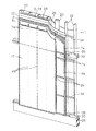
図1は、本発明に係る外断熱壁の実施例1を示す斜視図である。図2は、図1に示す実施例1において屋根部分を追加した状態の縦断面図である。図3は、図1に示す実施例1の要部横断面図である。図4は、図1に示す実施例1の要部縦断面図である。 FIG. 1 is a perspective view showing Example 1 of an outer heat insulating wall according to the present invention. FIG. 2 is a longitudinal sectional view of the first embodiment shown in FIG. 1 with a roof portion added. FIG. 3 is a cross-sectional view of the main part of the first embodiment shown in FIG. FIG. 4 is a longitudinal sectional view of an essential part of the first embodiment shown in FIG.
図1に示すように、実施例1の外断熱壁は、建築物外壁1の下地面2に設けられるものである。建築物外壁1は、基礎29の上に固定された土台30と、この土台30に連結された柱20および間柱22と、柱20および間柱22を水平方向に連結する桁31(図2)および梁32とを有する。
As shown in FIG. 1, the outer heat insulating wall of the first embodiment is provided on the
図2に示すように、柱20および間柱22の上部は、桁31に連結されている。桁31の上には、垂木61が載り、垂木61の上には野地板62が張られる。垂木61の先端は鼻かくし63となっている。軒裏65は、防火構造とされる。
As shown in FIG. 2, the upper portions of the
建築物外壁の下地面2は、柱20などに固定された構造用面材(または構造用合板)24の外表面である。構造用面材24は、柱20、間柱22、土台30、桁31および梁32などの構造躯体の外側面に固定される。さらに、建築物外壁1は、上記構造躯体の内側面に固定された内装材26を有する。構造用面材24と内装材26との間の空間には補強断熱材28を設ける。
The
図1、2に示すように、外断熱壁は、外壁内に通気路8aおよび通気路8bが形成され、これら通気路8a、8bに外気を導入し通過させることにより外壁内の結露を防止するとともに、断熱性、気密性を向上させる。さらに、通気胴縁は、縦方向(垂直方向)と横方向(水平方向)の両方に設けられるが、縦方向の通気胴縁7aと横方向の通気胴縁7bとの間には幅狭の通気路8bが形成される。
As shown in FIGS. 1 and 2, the outer heat insulating wall is formed with an air passage 8 a and an
さらに、外断熱壁は、建築物外壁の下地面2に設けられる板状の断熱材4と、この断熱材4の外側表面に設けられる細長板状の通気胴縁7a、7bと、この通気胴縁7a、7bの外側表面に固定される複合板10とを備える。複合板10は予め木質合板11に無機質を主成分とするモルタル18が設けられる。
Further, the outer heat insulating wall includes a plate-shaped
複合板10を固定する通気胴縁7bは、土台30、桁31ないし梁32のある箇所において、断熱材4に相当する厚みを有する胴縁固定桟36を設けて通気胴縁7bを上記土台30、桁31ないし梁32に直接固定する。こうすることにより断熱材4の外側に設ける複合板10を直接これら構造躯体に固定することができ、複合板10の重量によるだれ、下がり(位置ずれ)を防止する。
The
図3に示すように、内装材26は、柱20の内側面に内装材固定用留付具52により固定される。断熱材4は、板状で、その材料はポリスチレンフォーム、フェノールフォーム、グラスウールまたはロックウールなどで厚さは20〜80mmの範囲から、外断熱壁の使用目的に合った厚さを選定する。断熱材4は、通気胴縁7a、7bにより釘などの通気胴縁固定用留付具48により固定される。
As shown in FIG. 3, the
断熱材4を構造用面材24に固定する場合、構造用面材の下地面2と断熱材4との間にポリエチレンなどの防湿気密フィルム25を介在させる。防湿気密フィルム25としては、たとえば厚さ0.1mmとする。防湿気密フィルム25を介在させることにより壁体内への水蒸気の浸入を阻止する。
When the
図3、4に示すように、通気胴縁7a、7bは、断面矩形の細長板状で通気に必要な隙間9を形成できる厚みを有するとともに、断熱材4を構造用面材の下地面2に釘、木ねじなどの通気胴縁固定用留付具48により固定できる強度のあるものとする。
As shown in FIGS. 3 and 4, the ventilation trunk edges 7 a and 7 b are formed in an elongated plate shape having a rectangular cross section and have a thickness capable of forming a
通気胴縁7の材料としては木質系である。その断面寸法は、たとえば幅45〜90mm×厚さ15mm以上とする。なお、通気胴縁7で断熱材4を固定する際、防水紙6を介在させる。防水紙6は、通気胴縁7と断熱材4の間だけでなく、断熱材4の全面に設ける。防水紙6としては、アスファルトフェルトやポリエチレン、ポリエステル、ポリプロピレンなどの透湿防水シートを使用する。
The material of the
複合板10は、予め木質合板11に無機質を主成分とするモルタル層、たとえば軽量セメントモルタル層17を設けるもので、通気胴縁7a、7bに釘、木ねじなどの外装材固定用留付具46により固定される。複合板10の厚みは、たとえば木質合板11が7.5mm厚、軽量セメントモルタル層17が10mm厚である。さらに、木質合板11と軽量セメントモルタル層17との間に予め合成ゴムなどの防水層13を設けておく。防水層13を設けておくことにより、外側からの水の浸入を防止する。
The
さらに、防水層13の表面に無機質を主成分とする凹凸層15を設ける。このようにすると、木質合板11と軽量セメントモルタル層17との間に防水層13と凹凸層15がこの順に形成されることになり、凹凸層15は軽量セメントモルタル層17の付着を良好にする。凹凸層15の組成としてはセメントおよび骨材に若干の合成樹脂エマルジョンを加えたものである。
Furthermore, the uneven | corrugated layer 15 which has an inorganic substance as a main component is provided in the surface of the waterproof layer 13. If it does in this way, the waterproof layer 13 and the uneven | corrugated layer 15 will be formed in this order between the
軽量セメントモルタル層17の例としては、セメントに無機質混和剤と有機質混和剤を加えたものである。複合板10としては、たとえば株式会社ノダ製の商品名:モルダックが市販され、これを好適に使用できる。因みに、図3に示すように、複合板10の目地には目地処理材40を塗布する。
As an example of the lightweight
図4に示すように、水平方向の通気胴縁7bを固定する通気胴縁固定用留付具48は、構造用面材24を貫通し継手受材34に固定される。同様に、内装材26を固定する内装材固定用留付具52は内装材26を貫通し継手受材35に固定される。なお、複合板10の表面に、モルタルまたは接着剤を介してタイルを張っても良い。
As shown in FIG. 4, the ventilation trunk
次に、実施例1の外断熱壁の作用について説明する。図2において、断熱材4と複合板10との間に、通気胴縁7a、7bの厚みに相当する通気路8a、8b(隙間9)が形成され、この通気路8a、8bにより外壁内の結露を防ぎ、断熱、気密性能を向上させることができる。複合板10は、予め木質合板11に軽量セメントモルタル18を設けて形成されたものであるので、軽量セメントモルタル18の割れ、剥離、脱落などがなく複合板10の品質を安定させることができる。さらに、軽量セメントモルタル18を現場で塗布する必要がなく、施工期間を短くすることができ施工性も向上する。
Next, the effect | action of the outer heat insulation wall of Example 1 is demonstrated. In FIG. 2,
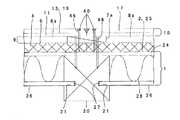
図5は、本発明に係る外断熱壁の実施例2を示す要部横断面図である。実施例2の外断熱壁は、通気胴縁7a(7b)の外側表面に固定される木質合板11と、この木質合板11の表面に設けられる軽量セメントモルタル層17とを備える。軽量セメントモルタル層17は木質合板11が通気胴縁7a(7b)の外側表面に固定された後に設けられる。木質合板11の表面には合成ゴムなどの防水層13と、無機質を主成分とする凹凸層15とが形成されている。
FIG. 5 is a cross-sectional view of an essential
防水層13を設けることにより、外側からの水の浸入を防止する。凹凸層15は軽量セメントモルタル層17の付着を良好にする。凹凸層15の組成としてはセメントおよび骨材に若干の合成樹脂エマルジョンを加えたものである。木質合板11に防水層と凹凸層を形成したものとしては、たとえば株式会社ノダ製の商品名:ラスカットが市販され、これを好適に使用できる。
Providing the waterproof layer 13 prevents water from entering from the outside. The uneven layer 15 improves the adhesion of the lightweight
また、木質合板の継目(または目地)部分には耐アルカリ性繊維などの網材(または目地補強材)42を張ってモルタル層を設けるが、この場合の網材42は木質合板の継目部分の限られた面積部分に追加的に設けてモルタル層を設ければ良いので、手間がかからず施工性も向上する。継目に設ける網材42の大きさは、幅が50〜300mmのものを使用すると良い。幅が50mm未満の場合は網材の補強効果が小さい。幅が300mmを超える場合は施工性(作業性)が悪くなる。
In addition, a mortar layer is provided on the joint (or joint) portion of the wood plywood by placing a net material (or joint reinforcement material) 42 such as an alkali-resistant fiber. In this case, the
また、予め木質合板11に軽量セメントモルタル層17を設ける際に10mm以下に薄く形成しておき、現場でさらに追加的に軽量セメントモルタルを塗り重ねて規定の厚さの軽量セメントモルタル層に仕上げても良い。さらに、木質合板11の表面に設けられるモルタル層の表面に、モルタルまたは接着剤を介してタイルを張っても良い。
In addition, when the lightweight
実施例2の外断熱壁の作用は、次のようである。すなわち、断熱材4と木質合板11との間に、通気胴縁7a(7b)の厚みに相当する通気路8a(8b)または隙間9が形成され、この通気路8a(8b)を利用することにより外壁内の結露を防ぎ、断熱、気密性能を向上させることができる。
The effect | action of the outer heat insulation wall of Example 2 is as follows. That is, an air passage 8a (8b) or a
軽量セメントモルタル層17は木質合板11が通気胴縁7a(7b)の外側表面に固定された後に設けられるので、外壁の表面に目地が現れず、雨水などの水の浸入を防ぎ防水性を向上させる。また、目地を目地処理材40で埋める手間がかからず施工性も向上する。図5に示した実施例2の外断熱壁のその他の構造と作用は、図1〜4に示した実施例1の外断熱壁と同じであるのでその説明を省略する。
The lightweight
図6は、本発明に係る外断熱壁の実施例3を示す要部横断面図である。実施例3の外断熱壁は、その内装材26が柱20の奥行き方向の途中に設けられる真壁造りの場合である。内装材26は、柱20(または間柱22)に固定された受材35に釘などの内装材固定用留付具52により固定される。図6におけるその他の構造と作用は、図1〜4に示した実施例1の外断熱壁と同じであるのでその説明を省略する。
FIG. 6 is a cross-sectional view of an essential part showing Embodiment 3 of the outer heat insulating wall according to the present invention. The outer heat insulating wall of Example 3 is a case of a true wall structure in which the
図7は、本発明に係る外断熱壁の実施例4を示す要部横断面図である。実施例4の外断熱壁は、その内装材26が柱20の奥行き方向の途中に設けらる真壁造りの場合である。内装材26は、その端部27が柱20(または間柱22)に形成された欠き込み21に挿入されることにより固定される。この際、内装材の端部27は、接着剤が併用されて固定されても良い。図7におけるその他の構造と作用は、図1〜4に示した実施例1の外断熱壁と同じであるのでその説明を省略する。
FIG. 7: is a principal part cross-sectional view which shows Example 4 of the outer heat insulation wall which concerns on this invention. The outer heat insulating wall of Example 4 is a case of a true wall structure in which the
以上この発明を図示の実施例について詳しく説明したが、それを以ってこの発明をそれらの実施例のみに限定するものではなく、この発明の精神を逸脱せずして種々改変を加えて多種多様の変形をなし得ることは云うまでもない。 The present invention has been described in detail with reference to the illustrated embodiments. However, the present invention is not limited to the embodiments, and various modifications can be made without departing from the spirit of the present invention. It goes without saying that various modifications can be made.
本発明の外断熱壁は、住宅、事務所その他の建築建物の外壁に利用可能である。 The outer heat insulating wall of the present invention can be used for the outer wall of a house, office or other architectural building.
1 建築物外壁
2 下地面
4 断熱材
5 外側表面
7a、7b 通気胴縁
8a、8b 通気路
9 隙間
10 複合板
11 木質合板
17 軽量セメントモルタル層(モルタル層)
DESCRIPTION OF
Claims (2)
Priority Applications (1)
| Application Number | Priority Date | Filing Date | Title |
|---|---|---|---|
| JP2004156381A JP2005336823A (en) | 2004-05-26 | 2004-05-26 | External heat-insulating wall |
Applications Claiming Priority (1)
| Application Number | Priority Date | Filing Date | Title |
|---|---|---|---|
| JP2004156381A JP2005336823A (en) | 2004-05-26 | 2004-05-26 | External heat-insulating wall |
Publications (2)
| Publication Number | Publication Date |
|---|---|
| JP2005336823A true JP2005336823A (en) | 2005-12-08 |
| JP2005336823A5 JP2005336823A5 (en) | 2007-03-15 |
Family
ID=35490691
Family Applications (1)
| Application Number | Title | Priority Date | Filing Date |
|---|---|---|---|
| JP2004156381A Pending JP2005336823A (en) | 2004-05-26 | 2004-05-26 | External heat-insulating wall |
Country Status (1)
| Country | Link |
|---|---|
| JP (1) | JP2005336823A (en) |
Cited By (8)
| Publication number | Priority date | Publication date | Assignee | Title |
|---|---|---|---|---|
| CN100373017C (en) * | 2005-12-26 | 2008-03-05 | 蔡伯中 | Thermal insulation aluminium light wall |
| JP2009013758A (en) * | 2007-07-09 | 2009-01-22 | Yabuhara Corp | Outer wall structure and its construction method |
| WO2009120092A1 (en) * | 2008-03-28 | 2009-10-01 | Selvaag Spinoff As | Structural wall |
| CN102304965A (en) * | 2011-05-30 | 2012-01-04 | 青岛格尔美环保涂料有限公司 | High self-cleaning inorganic heat insulation composite system |
| US20140245684A1 (en) * | 2011-08-18 | 2014-09-04 | Selvaag Gruppen As | External Wall with Plaster and Plaster Carrier |
| CN105019623A (en) * | 2015-07-09 | 2015-11-04 | 中建钢构有限公司 | Building exterior wall double-layer heat insulation ventilation cuticle structure |
| JP2016014298A (en) * | 2014-07-03 | 2016-01-28 | 旭化成ホームズ株式会社 | Heat-insulating air-tight exterior wall structure |
| JP2016191201A (en) * | 2015-03-30 | 2016-11-10 | 積水化学工業株式会社 | Heat-insulating ventilation wall structure of building |
-
2004
- 2004-05-26 JP JP2004156381A patent/JP2005336823A/en active Pending
Cited By (10)
| Publication number | Priority date | Publication date | Assignee | Title |
|---|---|---|---|---|
| CN100373017C (en) * | 2005-12-26 | 2008-03-05 | 蔡伯中 | Thermal insulation aluminium light wall |
| JP2009013758A (en) * | 2007-07-09 | 2009-01-22 | Yabuhara Corp | Outer wall structure and its construction method |
| JP4662965B2 (en) * | 2007-07-09 | 2011-03-30 | 株式会社ヤブ原 | Exterior wall structure and construction method |
| WO2009120092A1 (en) * | 2008-03-28 | 2009-10-01 | Selvaag Spinoff As | Structural wall |
| CN102304965A (en) * | 2011-05-30 | 2012-01-04 | 青岛格尔美环保涂料有限公司 | High self-cleaning inorganic heat insulation composite system |
| US20140245684A1 (en) * | 2011-08-18 | 2014-09-04 | Selvaag Gruppen As | External Wall with Plaster and Plaster Carrier |
| US9297165B2 (en) * | 2011-08-18 | 2016-03-29 | Selvaag Gruppen As | External wall with plaster and plaster carrier |
| JP2016014298A (en) * | 2014-07-03 | 2016-01-28 | 旭化成ホームズ株式会社 | Heat-insulating air-tight exterior wall structure |
| JP2016191201A (en) * | 2015-03-30 | 2016-11-10 | 積水化学工業株式会社 | Heat-insulating ventilation wall structure of building |
| CN105019623A (en) * | 2015-07-09 | 2015-11-04 | 中建钢构有限公司 | Building exterior wall double-layer heat insulation ventilation cuticle structure |
Similar Documents
| Publication | Publication Date | Title |
|---|---|---|
| US11377860B2 (en) | System and method for a vented and water control siding | |
| US10227773B2 (en) | NP-EIFS non-permissive exterior insulation and finish systems concept technology and details | |
| US8621799B2 (en) | External wall and roof systems | |
| JP2021513622A (en) | Prefabricated insulated building panel with at least one hardened cementum layer bonded to the insulation | |
| JPH0387441A (en) | Finishing process of external heat-insulating material | |
| US20050235598A1 (en) | Wall construction method | |
| US20130312347A1 (en) | Building system with multi-function insulation barrier | |
| JP2002161623A (en) | External-facing backing structure and external-facing backing construction method | |
| JP4480181B2 (en) | Outer insulation structure of wooden building | |
| JP2005336823A (en) | External heat-insulating wall | |
| JP2000204688A (en) | External heat insulating structure and external heat insulating construction method for building | |
| JP2011256536A (en) | Exterior wall structure of wooden building | |
| JP4596486B2 (en) | Outer insulation structure of wooden building | |
| JP3830463B2 (en) | Waterproofing method for buildings | |
| KR20160109312A (en) | Exterior finishing method for sandwich panel wall and the structures thereof | |
| JP2016151124A (en) | Roof structure | |
| JP2003278285A (en) | Building sheet, building and construction method | |
| US20220282477A1 (en) | Apparatus and method for exposed insulated wallboard | |
| JP2007177398A (en) | Flat plate-combined form panel | |
| JPH05195589A (en) | Exterior waterproofing construction | |
| GB2536036A (en) | Improvements in and relating to pre-fabricated stone panels, a method of constructing a wall from pre-fabricated stone panels and a construction kit | |
| IES86579B2 (en) | Improvements in and relating to pre-fabricated stone panels, a method of constructing a wall from pre-fabricated stone panels and a construction kit comprising pre-fabricated stone panels | |
| JP2004270383A (en) | Lightweight, construction time reduction type fire resistant heat insulative roof asphalt waterproof method | |
| JPH02140358A (en) | Outer wall structure of construction | |
| JP2007231716A (en) | Heat shielding and insulating construction method for building |
Legal Events
| Date | Code | Title | Description |
|---|---|---|---|
| A521 | Written amendment |
Free format text: JAPANESE INTERMEDIATE CODE: A523 Effective date: 20070131 |
|
| A621 | Written request for application examination |
Free format text: JAPANESE INTERMEDIATE CODE: A621 Effective date: 20070131 |
|
| A977 | Report on retrieval |
Effective date: 20081106 Free format text: JAPANESE INTERMEDIATE CODE: A971007 |
|
| A131 | Notification of reasons for refusal |
Free format text: JAPANESE INTERMEDIATE CODE: A131 Effective date: 20081118 |
|
| A521 | Written amendment |
Free format text: JAPANESE INTERMEDIATE CODE: A523 Effective date: 20090114 |
|
| RD02 | Notification of acceptance of power of attorney |
Effective date: 20090115 Free format text: JAPANESE INTERMEDIATE CODE: A7422 |
|
| A02 | Decision of refusal |
Free format text: JAPANESE INTERMEDIATE CODE: A02 Effective date: 20090407 |