JP2005336049A - High thermal efficiency glass microchannel and method for forming the same - Google Patents
High thermal efficiency glass microchannel and method for forming the same Download PDFInfo
- Publication number
- JP2005336049A JP2005336049A JP2005121449A JP2005121449A JP2005336049A JP 2005336049 A JP2005336049 A JP 2005336049A JP 2005121449 A JP2005121449 A JP 2005121449A JP 2005121449 A JP2005121449 A JP 2005121449A JP 2005336049 A JP2005336049 A JP 2005336049A
- Authority
- JP
- Japan
- Prior art keywords
- sheet
- glass
- mold
- microfluidic device
- molded
- Prior art date
- Legal status (The legal status is an assumption and is not a legal conclusion. Google has not performed a legal analysis and makes no representation as to the accuracy of the status listed.)
- Pending
Links
Images


Classifications
-
- B—PERFORMING OPERATIONS; TRANSPORTING
- B81—MICROSTRUCTURAL TECHNOLOGY
- B81C—PROCESSES OR APPARATUS SPECIALLY ADAPTED FOR THE MANUFACTURE OR TREATMENT OF MICROSTRUCTURAL DEVICES OR SYSTEMS
- B81C1/00—Manufacture or treatment of devices or systems in or on a substrate
- B81C1/00015—Manufacture or treatment of devices or systems in or on a substrate for manufacturing microsystems
- B81C1/00023—Manufacture or treatment of devices or systems in or on a substrate for manufacturing microsystems without movable or flexible elements
- B81C1/00119—Arrangement of basic structures like cavities or channels, e.g. suitable for microfluidic systems
-
- B—PERFORMING OPERATIONS; TRANSPORTING
- B01—PHYSICAL OR CHEMICAL PROCESSES OR APPARATUS IN GENERAL
- B01L—CHEMICAL OR PHYSICAL LABORATORY APPARATUS FOR GENERAL USE
- B01L3/00—Containers or dishes for laboratory use, e.g. laboratory glassware; Droppers
- B01L3/50—Containers for the purpose of retaining a material to be analysed, e.g. test tubes
- B01L3/502—Containers for the purpose of retaining a material to be analysed, e.g. test tubes with fluid transport, e.g. in multi-compartment structures
- B01L3/5027—Containers for the purpose of retaining a material to be analysed, e.g. test tubes with fluid transport, e.g. in multi-compartment structures by integrated microfluidic structures, i.e. dimensions of channels and chambers are such that surface tension forces are important, e.g. lab-on-a-chip
- B01L3/502707—Containers for the purpose of retaining a material to be analysed, e.g. test tubes with fluid transport, e.g. in multi-compartment structures by integrated microfluidic structures, i.e. dimensions of channels and chambers are such that surface tension forces are important, e.g. lab-on-a-chip characterised by the manufacture of the container or its components
-
- F—MECHANICAL ENGINEERING; LIGHTING; HEATING; WEAPONS; BLASTING
- F28—HEAT EXCHANGE IN GENERAL
- F28F—DETAILS OF HEAT-EXCHANGE AND HEAT-TRANSFER APPARATUS, OF GENERAL APPLICATION
- F28F21/00—Constructions of heat-exchange apparatus characterised by the selection of particular materials
- F28F21/006—Constructions of heat-exchange apparatus characterised by the selection of particular materials of glass
-
- F—MECHANICAL ENGINEERING; LIGHTING; HEATING; WEAPONS; BLASTING
- F28—HEAT EXCHANGE IN GENERAL
- F28F—DETAILS OF HEAT-EXCHANGE AND HEAT-TRANSFER APPARATUS, OF GENERAL APPLICATION
- F28F3/00—Plate-like or laminated elements; Assemblies of plate-like or laminated elements
- F28F3/12—Elements constructed in the shape of a hollow panel, e.g. with channels
-
- B—PERFORMING OPERATIONS; TRANSPORTING
- B01—PHYSICAL OR CHEMICAL PROCESSES OR APPARATUS IN GENERAL
- B01L—CHEMICAL OR PHYSICAL LABORATORY APPARATUS FOR GENERAL USE
- B01L2200/00—Solutions for specific problems relating to chemical or physical laboratory apparatus
- B01L2200/12—Specific details about manufacturing devices
-
- B—PERFORMING OPERATIONS; TRANSPORTING
- B01—PHYSICAL OR CHEMICAL PROCESSES OR APPARATUS IN GENERAL
- B01L—CHEMICAL OR PHYSICAL LABORATORY APPARATUS FOR GENERAL USE
- B01L2300/00—Additional constructional details
- B01L2300/12—Specific details about materials
-
- B—PERFORMING OPERATIONS; TRANSPORTING
- B81—MICROSTRUCTURAL TECHNOLOGY
- B81B—MICROSTRUCTURAL DEVICES OR SYSTEMS, e.g. MICROMECHANICAL DEVICES
- B81B2201/00—Specific applications of microelectromechanical systems
- B81B2201/05—Microfluidics
- B81B2201/058—Microfluidics not provided for in B81B2201/051 - B81B2201/054
-
- F—MECHANICAL ENGINEERING; LIGHTING; HEATING; WEAPONS; BLASTING
- F28—HEAT EXCHANGE IN GENERAL
- F28F—DETAILS OF HEAT-EXCHANGE AND HEAT-TRANSFER APPARATUS, OF GENERAL APPLICATION
- F28F2260/00—Heat exchangers or heat exchange elements having special size, e.g. microstructures
- F28F2260/02—Heat exchangers or heat exchange elements having special size, e.g. microstructures having microchannels
Abstract
Description
本発明は、広くはマイクロ流体素子、及びかかる素子の製造方法に関し、特に高熱効率ガラス、ガラス−セラミックまたはセラミックマイクロチャンネルまたはマイクロ流体素子、及びかかる素子の製造方法に関する。 The present invention relates generally to microfluidic devices and methods of manufacturing such devices, and more particularly to high thermal efficiency glass, glass-ceramic or ceramic microchannels or microfluidic devices, and methods of manufacturing such devices.
マイクロチャンネルまたはマイクロ流体素子は、広くは内部で流体がさまざまな方法で方向づけられたり処理されたりするように、大体10μmから1000μmの範囲にある特有の寸法を持った流路を有する素子として理解されている。かかる素子は、化学的及び生物学的な処理技術における革新的な変化を可能にする為、大いに有望であると考えられている。その理由は、特にマイクロ流体素子の熱及び物質伝達率が、従来の化学的な処理システムにおいて達成し得る率を桁違いに超えて増加するからである。 A microchannel or microfluidic device is broadly understood as a device having a channel with a characteristic dimension roughly in the range of 10 μm to 1000 μm so that the fluid is directed and processed in various ways inside. ing. Such devices are considered highly promising because they enable innovative changes in chemical and biological processing techniques. This is because, in particular, the heat and mass transfer rates of microfluidic devices increase orders of magnitude beyond those achievable in conventional chemical processing systems.
ガラスまたはガラス−セラミックでのマイクロ流体の回路は、すぐれた耐化学性を有するという利点を有している。しかし、ガラスやガラス−セラミックは相対的に熱の伝導性が悪い一方、ほとんどの化学的合成においては、熱交換が重要である。正確且つ安全な局所的な熱管理が、広くは相対的により高い濃度、圧力、温度での化学的処理を可能にし、結果として、ほとんどの場合において、よりよい歩留まりとより高効率化へとつながるのである。 Microfluidic circuits in glass or glass-ceramic have the advantage of having excellent chemical resistance. However, while glass and glass-ceramics have relatively poor thermal conductivity, heat exchange is important in most chemical synthesis. Accurate and safe local thermal management generally allows chemical processing at relatively higher concentrations, pressures, and temperatures, resulting in better yields and higher efficiency in most cases It is.
本発明は、良好な表面特性と十分な強度とを有する薄いガラス、ガラス−セラミックまたはセラミックのシート材料から形成されるマイクロ流体チャンネルを有する素子を提供し、更にはかかる素子とチャンネルを確実に且つ効率的に製造するための方法を提供する。薄壁性のマイクロチャンネルは、すぐれた化学的耐久性と熱抵抗を示しながらも効率的な熱交換を可能にすることができる。本発明の成形工程は、得られた素子が熱交換を最大化にしながらも、簡略且つ確実な製造工程を提供する。 The present invention provides a device having a microfluidic channel formed from a thin glass, glass-ceramic or ceramic sheet material having good surface properties and sufficient strength, and further ensures that the device and channel are A method for efficient manufacturing is provided. Thin walled microchannels can enable efficient heat exchange while exhibiting excellent chemical durability and thermal resistance. The molding process of the present invention provides a simple and reliable manufacturing process while the resulting element maximizes heat exchange.
本発明の一つ実施例によれば、マイクロ流体素子は、ガラスまたはセラミックの物質からなる成形シートを含む。成形シートは、その第1の面上に1つまたはそれ以上の第1のマイクロチャンネル、そして第1の面とは反対側の第2の面上に、1つまたはそれ以上の第2のマイクロチャンネルを有するように形成される。第2のチャンネルは、第1のチャンネルに対し相補的である。第1のチャンネルは、成形シートの第1の面に接着させたガラスまたはガラス−セラミック物質からなる第1の平板によって実質的に閉塞されており、第2のチャンネルは、第2の面に接着させたガラスまたはガラス−セラミック物質からなる第2の平板によって実質的に閉塞され得る。 According to one embodiment of the present invention, the microfluidic device includes a molded sheet made of a glass or ceramic material. The molded sheet has one or more first microchannels on its first side and one or more second microchannels on a second side opposite the first side. It is formed to have a channel. The second channel is complementary to the first channel. The first channel is substantially occluded by a first plate of glass or glass-ceramic material adhered to the first side of the molded sheet, and the second channel adheres to the second side. It can be substantially occluded by a second plate of glass or glass-ceramic material.
本発明の他の実施例によれば、マイクロ流体素子を形成するための方法が提供されている。この方法は、単一表面の金型を提供し、金型上にガラスまたはセラミック化可能なガラスのシートを位置決めし、金型とシートを加熱し、そして金型にシートを密着させるようにシートにガス圧力差を与えることを含む。結果として、シートの少なくとも一方の面、広くは両面にマイクロチャンネルが形成される。次に、マイクロチャンネルを含むシートの少なくとも一方の面全面上に、ガラスまたはセラミック化可能なガラスを接着することにより、マイクロチャンネルは実質的に閉塞されたり、または取り囲まれる。 According to another embodiment of the invention, a method for forming a microfluidic device is provided. This method provides a single surface mold, positions a sheet of glass or ceramizable glass on the mold, heats the mold and sheet, and adheres the sheet to the mold Including applying a gas pressure difference to. As a result, microchannels are formed on at least one side of the sheet, broadly both sides. The microchannel is then substantially occluded or surrounded by adhering glass or ceramizable glass over the entire surface of at least one side of the sheet containing the microchannel.
本発明のさらに他の実施例によれば、マイクロ流体素子を形成する方法が提供され、この方法は、動いている金型全面上に第1の軟質ガラスシートを展開するステップを含む。第1の軟質ガラスシートは金型の反対側に第1の面を有し、第1の面と反対側には金型上にある第2の面を有する。この方法は更に、金型に前記軟質ガラスシートを密着させるようにする真空成形を含み、その結果、第1及び第2の両面上にマイクロチャンネルを有する密着シートを形成する。この方法は更に、第2の軟質ガラスシートを前記密着シートの前記第1の面上に展開することを含み、その結果、前記第2の軟質ガラスシートを前記密着シートに接着させ、前記第1の面上に前記マイクロチャンネルを実質的に閉塞させることになる。この方法は更に、前記金型から前記密着シートを取り外すことを含む。この方法は更に、第3の軟質ガラスシートを前記密着シートの前記第2の面上に展開することを含み、その結果、前記第2の軟質ガラスシートを前記密着シートに接着させ、前記第2の面上に前記マイクロチャンネルを実質的に閉塞させることになる。 In accordance with yet another embodiment of the present invention, a method for forming a microfluidic device is provided, the method including the step of deploying a first soft glass sheet over the moving mold. The first soft glass sheet has a first surface on the opposite side of the mold and a second surface on the mold opposite to the first surface. The method further includes vacuum forming to allow the soft glass sheet to adhere to the mold, resulting in the formation of an adhesive sheet having microchannels on both the first and second surfaces. The method further includes developing a second soft glass sheet on the first surface of the adhesive sheet, so that the second soft glass sheet is adhered to the adhesive sheet, and the first The microchannel is substantially occluded on the surface. The method further includes removing the adhesive sheet from the mold. The method further includes deploying a third soft glass sheet on the second surface of the adhesive sheet, so that the second soft glass sheet is adhered to the adhesive sheet, and the second The microchannel is substantially occluded on the surface.
前述の概要及び以下の詳細な説明は、共に本発明の実施例を示したものであり、請求されている本発明の本質及び特性を理解するための概略、または構成を提供することを目的としている、という事を理解すべきである。添付図は、本発明の更なる理解を提供するように、この明細書の一部に取り込まれ構成要素となっている。添付図は、本発明の種々の実施例を図示したものであり、解説とともに本発明の原理、及び工程を説明するための働きをなしている。 Both the foregoing summary and the following detailed description are exemplary of the invention and are intended to provide an overview or configuration in order to understand the nature and characteristics of the claimed invention. You should understand that. The accompanying drawings are incorporated into and constitute a part of this specification so as to provide a further understanding of the invention. The accompanying drawings illustrate various embodiments of the invention and together with the description serve to explain the principles and processes of the invention.
本発明は、良好な表面特性と十分な強度を有する薄いガラス、ガラス−セラミックまたはセラミックのシート材料から形成されるマイクロ流体チャンネルを有する素子を提供し、更には、かかる素子とチャンネルを確実に且つ効率的に製造するための方法を提供するものである。本発明の方法は、所望の薄壁性で且つ高表面品質を有するガラス、ガラス−セラミックまたはセラミックのマイクロチャンネルを実現するために、ガス圧力差による成形を与える。得られた薄壁性のマイクロチャンネルは、すぐれた化学的耐久性と熱抵抗を示しながら、効率的な熱交換を可能にする。本発明の成形工程は、得られた素子が熱交換を最大化にしながらも、簡略且つ確実な製造方法を提供する。 The present invention provides a device having a microfluidic channel formed from a thin glass, glass-ceramic or ceramic sheet material having good surface properties and sufficient strength, and further ensures that the device and channel are A method for efficient production is provided. The method of the present invention provides molding by gas pressure differential to achieve glass, glass-ceramic or ceramic microchannels with the desired thin wall properties and high surface quality. The resulting thin-walled microchannels enable efficient heat exchange while exhibiting excellent chemical durability and thermal resistance. The molding process of the present invention provides a simple and reliable manufacturing method while the resulting element maximizes heat exchange.
本発明によれば、マイクロチャンネルは、単にミクロ構造の平板を積み重ねることによるのではなく、3次元のガラス、ガラス−セラミックまたはセラミック状のものを閉塞させることを含む方法により作られる。本発明の一形態を構成する具体例としての方法を、図1から図7に関連して以下に記述する。 According to the present invention, the microchannels are made by a method that involves plugging a three-dimensional glass, glass-ceramic or ceramic-like material, rather than simply by stacking microstructured flat plates. An exemplary method for constructing an aspect of the present invention is described below in connection with FIGS.
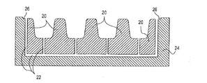
図1は、本発明の一形態に関連して有用な装置10の断面図を示している。装置10は、あらかじめ機械加工されているか、または別の方法として、ティッセン−フランス社(Thyssen-France,78 Maurepas,France)から入手できる耐熱性鋼板「NS 30/ASI 310」のような適当な材料から形成される流体回路金型20を含む。金型20は真空分布のためのミクロ通路22を含む。金型20は、これを取り囲むような真空密閉のための面、または出っ張り26を有する真空ボックス24のような真空密閉構造中に置かれる。真空ボックス24の内部容積は、図中で示されていないが真空ポンプのような真空源に接続されている。
FIG. 1 shows a cross-sectional view of an apparatus 10 useful in connection with one aspect of the present invention. The apparatus 10 may be pre-machined or, alternatively, a suitable material such as a heat resistant steel plate “
使用に先立ち、金型20をカルシウム水酸化物(例えば、アルコール+「Disperbick190」の0.5%検査液)のような適当な離型剤でコーティングする。Disperbick190はBYK−Chemie社(BYK-Chemie Gmbh,Abelstr.14D-46483 Wesel,Germany)から簡単に入手することができる。離型剤は、金型20の全面上に均一に噴霧することが望ましい。
Prior to use,
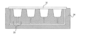
図2に示されているように、その後、適当なガラス物質からなり、面または出っ張り26を覆うような大きさの表面積を有する薄板30を、金型20に取り付ける。ガラスは、例えばコーニング社(Corning Incorporated,Corning NY,USA)から入手できる「Corning 1737」であることができる。
As shown in FIG. 2, a
薄板30と金型20は、その後、ガラス物質の焼きなまし点以上の温度まで共に加熱されるが、ガラス物質の軟化点以下近辺であることが望ましい。約721℃の焼きなまし点と約925℃の軟化点を有する「Corning 1737」の場合には、金型と薄板は約20分以上、約870℃まで加熱され得る。
The
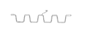
その後、金型20の側面に薄板30が密着するような十分な時間、真空が真空ボックス24に付与される。その結果、図3に描写されているような成形シートが得られる。代替案として、ガス圧力を金型20の反対側の薄板30の面に付与することができ、ミクロ通路22は圧力を解放するためだけに使用される。さらなる代替案として、金型の外側からの陽圧と金型中の真空を、同時に働かせることもできる。
Thereafter, a vacuum is applied to the
薄板30を成形シート32に再整形することに加え、真空成形は薄板30を再吸引する(真空再吸引)効果をも有する。その結果、成形シート32は、概して本来の薄板30よりも薄くなり、物質が金型に吸い込まれた領域は特に薄くなる。この真空成形方法は、それ故に、0.3mmかそれ以下の薄さ、望ましくは約0.2mmから約0.7mmの範囲かそれ以下の範囲の薄さの壁構造形成を、確実に且つ再現性良く行うことを可能にする。
他方、適当な厚さの出発物質を使用して、より厚さのある壁構造をも、この方法を使用することにより形成することができ得る。これは、高圧、または超高圧用途での使用に有効である約0.7mmから約3mmの範囲の厚さを含む。
In addition to reshaping the
On the other hand, using an appropriate thickness of starting material, thicker wall structures can also be formed by using this method. This includes thicknesses in the range of about 0.7 mm to about 3 mm that are useful for use in high pressure or ultra high pressure applications.
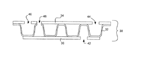
真空成形後、金型20と成形シート32は、成形シート32がその成形された形を保持できるような十分低い温度まで冷却されるが、金型20からの取り外しが容易であるように十分高い温度であることが望ましい。例えば、「Corning 1737」では、薄板30は2分間以上かけて約750℃まで冷却され得る。その後、金型20から成形シート32を取り外すために、軽い空気圧が真空チャンネル22に付与される。離型剤は、このステップを著しく容易にする。得られた成形シート32が、図4に断面で示されている。
After vacuum forming, the
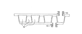
次に、上部と下部の平板34、36を図5の断面に示されるように、成形シート32に対向して配置し、組立品38を形成する。組立品38をともに接着する前に、穴あけ、研削または他の適当な方法により、所望の入力及び出力穴が上部平板34 と/または 下部平板36を貫通して(必要に応じて前記成形シート32をも貫通して)形成される。図5に示されているように、アクセス穴は(図の右側にある)穴42と44の場合のように反対側の平板に形成されるか、または、必要に応じて穴46と48の場合のように同一の平板に形成される。アクセス穴は、穴48の場合のように上部平板34と成形シート32の両方を貫通して延長してもよい。
Next, as shown in the cross section of FIG. 5, the upper and lower
その後、図6に示されているように、組立品38は実例アクセス穴42、44、46、48を持つ閉塞された、または取り囲まれたマイクロチャンネル、または通路40を有するマイクロ流体素子50を形成するように接着される。組立品38の接着は、「Corning1737」ガラス平板と「Corning1737」成形シートのガラス対ガラス熱接着により、組立品38を約90分間約870℃に保持することにより仕上げることが望ましい。接着する前に穴あけや別の方法でアクセス穴を形成することにより、穴形成工程から生じるミクロな亀裂や表面損傷が少しでもあった場合には焼きなますことができる。
Thereafter, as shown in FIG. 6, the
上記の発明方法例は、同じ方法の段階において薄いガラス層によって隔てられた対の回路を形成することができる。例えば、0.5mmの厚さのシートから始まると、側壁58の厚さは0.4mmから0.3mmの範囲であることができ、熱交換に対しほんの僅かな障壁を示す。必要に応じて0.7mmまたは1mmの厚さのシートから始めることにより、側壁はより厚くなり得る。
The above inventive method example can form a pair of circuits separated by a thin glass layer in the same method step. For example, starting with a 0.5 mm thick sheet, the
図7に示された標準の流体コネクタ52は、重合接着、または他の互換性があるガラス接着手段により接着することができる。
The
上述の成形方法は、成形シート32の上部及び下部面上に、対の相補的なチャンネルパターンを容易に製作できるので、このように形成されたマイクロ流体素子の一つの固有の用途は熱交換である。図8に示されるように、成形シート32の片側のチャンネルは第1の流体F1を含有し、一方、成形シート32の反対側にあるチャンネルは、第2の流体F2を含有し得る。交互のチャンネルは最低限の薄さのガラス板によって隔てられているため、素早く効率的な熱伝達が可能である。
Since the above-described forming method can easily produce a pair of complementary channel patterns on the upper and lower surfaces of the forming
図9は、マイクロ流体回路における図8のような交互のチャンネルの、一つの可能な配置の平面図を示している。チャンネル54は、各チャンネルの各端に設けられたアクセス穴56を含め一直線で平行に配置され得る。図で矢印と陰影付けにより示唆されているように、かかるチャンネルは逆の流れをもつ交互のチャンネル中の二つの流体のために使用することができる。または必要に応じて、平行な流れをもつような他の形態では高性能熱交換のために使用することができる。
FIG. 9 shows a plan view of one possible arrangement of alternating channels as in FIG. 8 in a microfluidic circuit. The
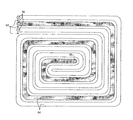
図10は、図8のような交互のチャンネルの、他のあり得る配置の平面図を示している。図10において、二つの交互のチャンネル54は外縁及びらせん形の中心にあるアクセス穴56を含み、同軸のらせん形中に共に配置される。
FIG. 10 shows a plan view of another possible arrangement of alternating channels as in FIG. In FIG. 10, two alternating
ここに記述された方法によって作られたマイクロチャンネルの配置は、図9、10に示されたもののように交互で且つ非連通なチャンネル配置に限定される必要はない。 Microchannel arrangements made by the methods described herein need not be limited to alternating and non-communication channel arrangements such as those shown in FIGS.
例えば、必要に応じて成形シート32が形成される金型は、成形シート32の片側の幾つかまたは全てのチャンネルを最小にするように設計され得る。結果として、図11のマイクロ流体素子50に示されているように、最小化されたチャンネル60に普通のチャンネルが散在することになる。得られた最小化されたチャンネルは、その後、流体回路デザインから完全に削除しても良い。必要に応じて、他の方法として近接した流体回路チャンネル同士を断熱する為の補助として、最小化されたチャンネル60を空気、ヘリウム、他のガス、または不完全真空でも満たすことができる。逆に、高い熱質量、相対的に高い熱伝導率、及び温度均一性が要求される場合には、最小化されたチャンネルを水、または他の流体で満たすこともできる。
For example, the mold in which the molded
成形シートの片側に、最小化されたチャンネルサイズを有する本発明に準ずる素子の実施例が、図12の平面図に示されている。この実施例においては、最小化されたチャンネル60はマイクロ流体回路に含まれておらず、最小化されていないチャンネル54がアクセス穴56を含み提供されている。図12に示されているような実施例においては、最小化されていないチャンネルを単板で閉塞させることが可能である。
An embodiment of a device according to the invention having a minimized channel size on one side of the molded sheet is shown in the plan view of FIG. In this embodiment, the minimized
本発明におけるマイクロ流体素子の他の実施例では、流体のやり取りのための開口を、成形シート32の片側の流体チャンネルと反対側の相補的な流体チャンネルとの間に、要望どおりに設けることができ、これは成形シート32中のチャンネル壁の選択箇所を除去することによりなされる。例えば、図13に示された破線の境界41中の物質を成形シート32から(研削、穴あけ、または他の適当な方法により)除去することにより、隣接する交互のチャンネル43と45の間に流体結合、または貫通孔を設けることができる。除去される物質は、(図の内外の方向において)チャンネルに沿って長々と延長する必要はないので、成形シートは略その構造的完全性を保つことができる。
In another embodiment of the microfluidic device of the present invention, an opening for fluid exchange may be provided as desired between the fluid channel on one side of the molded
本発明のマイクロ流体素子は、コーニング社(Corning Incorporated,Corning,New York,USA)から入手できる「Corning0211」、「Corning7059」、「Corning1737」と、Glaverbelグループ(Glaverbel Group,1170 Brussels,Belgium)から入手できる「Glaverbel D 263」を含む種々のガラス構成物を使用して製造することに成功している。これらの中で、「Corning1737」は約37.6x10⁻⁷Cという最も小さい熱膨張率を示す。「Corning1737」から形成されるマイクロ流体素子は、流体温度が650℃以下での使用に適している。Keraglass社(77 Bagneau sur Loing,France)から入手できる「Kerablack」のようなアルミニウムホウ化ケイ酸塩も使用することができる。マイクロ流体素子が上記のように形成された後、「Kerablack」をセラミック化することによりセラミックガラス(Vitroceram)になり、約-2x10⁻⁷という超低の熱膨張率を示す。 The microfluidic device of the present invention is available from Corning 0211, Corning 7059, Corning 1737 and Glaverbel Group (1170 Brussels, Belgium) available from Corning Incorporated, Corning, New York, USA. It has been successfully manufactured using a variety of glass constructions including “Glaverbel D 263”. Among these, “Corning 1737” shows the smallest thermal expansion coefficient of about 37.6 × 10 −7 C. The microfluidic device formed from “Corning 1737” is suitable for use at a fluid temperature of 650 ° C. or lower. Aluminum borosilicates such as “Kerable” available from Keraglass (77 Bagneau sur Loing, France) can also be used. After the microfluidic device is formed as described above, “Kerable” is converted into ceramic glass (Vitroceram) by ceramization and exhibits an extremely low coefficient of thermal expansion of about −2 × 10 −7 .
本発明の更に他の実施例として、適度に近い熱膨張率を有する二つのガラス物質を、単一のマイクロ流体素子を形成するために使用することができる。例えば、素子50中の通路を閉塞する為に使用する上部及び下部シートを、「Pyrex7740」(図5、6参照)から形成する一方、成形シート32は「Corning1737」から形成することができる。これら二つのガラス物質の約100℃の軟化点の違いは、約780℃での熱封止を可能にする。このより低い熱封止温度は、場合によって成形シート32の真空成形後の変形を防止するために役立つ。
As yet another embodiment of the present invention, two glass materials having reasonably close coefficients of thermal expansion can be used to form a single microfluidic device. For example, the upper and lower sheets used to close the passage in the
<好ましい製造工程>
上述の等温工程は試作品構築のために行われているものであり、極めて小規模製造に適している。より費用効率が高く、効率的な生産工程を図14(A)から図14(F)に関連して以下に説明する。
<Preferred manufacturing process>
The isothermal process described above is performed for the construction of a prototype, and is very suitable for small-scale manufacturing. A more cost effective and efficient production process is described below with reference to FIGS. 14 (A) to 14 (F).
図14(A)に示されているように、粘着性のあるガラス物質の塊70が、タンク供給機(図示せず)から加熱された回転ローラーの72、74の上に供給される。軟ガラスシート76は、動いている金型78上に展開された後すぐに真空成形され、図14(B)に示されているような成形シート80を形成し、その厚さは真空引きにより軟ガラスシート76に対して減じられる。次に直ちに行われる第2の段階で、第2の軟ガラスシート82が、図14(C)に示されているように成形シート80上に置かれる。第二の軟ガラスシートは、図14(D)に示されているように直ちに成形シート80の上面を閉じ、閉塞された上部チャンネル90を形成する。従って、上部チャンネル90は約5秒から10秒という短い時間で、素早く形成され閉塞される。閉塞された上部チャンネル90を有する成形シートは、その後、金型から取り外され支持材82の上に反転した状態で置かれる。前の段階で閉塞されていない相補的な流体回路は、その後、図14(E)で示されるように第三の軟ガラスシート84で覆われ、閉塞された下部チャンネル100を形成し、結果として図14(F)のマイクロ流体素子50が得られる。
As shown in FIG. 14A, a
例えば、「7740Pyrex」を形成する為に好ましい温熱条件は650℃に加熱したローラーと金型上への1350℃のガラス送り出しである。離型材は、アセチレンクラッキングに由来するガスブラックが望ましい。ガラスシートが薄くなるに従い、ローラー温度は高くするべきである。0.8mmに圧延されて、真空成形されたシートが実例説明されており、成形シートの底部のガラス厚は0.2mm未満を示している。 For example, the preferred thermal conditions for forming “7740 Pyrex” are a roller heated to 650 ° C. and glass feed at 1350 ° C. onto a mold. The release material is preferably gas black derived from acetylene cracking. As the glass sheet becomes thinner, the roller temperature should increase. A sheet that has been rolled to 0.8 mm and vacuum formed is illustrated by way of example, with the glass thickness at the bottom of the formed sheet being less than 0.2 mm.
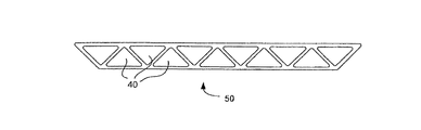
本発明のマイクロ流体素子及び本発明の工程により製造されるマイクロ流体素子は、ほぼ垂直のチャンネル壁を有するデザインに限定される必要はない。図15は、三角形のチャンネル40を有するマイクロ流体素子50の断面図を示している。この構造及び他の構造が本発明により容易に達成可能である。
The microfluidic device of the present invention and the microfluidic device produced by the process of the present invention need not be limited to designs having substantially vertical channel walls. FIG. 15 shows a cross-sectional view of a
本発明の工程及び方法は、再現可能で且つ確実な極めて薄壁性のガラスマイクロチャンネルの形成を可能にする。結果として得られる本発明のマイクロ流体素子は、特に高性能マイクロ流体熱交換に適している。 The process and method of the present invention allows the formation of reproducible and reliable very thin walled glass microchannels. The resulting microfluidic device of the present invention is particularly suitable for high performance microfluidic heat exchange.
マイクロ流体素子を形成する他の方法と比較して、現行の発明はチャンネルの断面積に対する隣接したチャンネル間の壁面積を大きくすることを可能にする。大きい壁面積は主に、開示された方法で達成可能である比較的高いチャンネルアスペクト比(チャンネル高さのチャンネル幅に対する割合)が2:1或いはそれ以上であることに帰する。 Compared to other methods of forming microfluidic devices, the current invention allows the wall area between adjacent channels to be increased relative to the cross-sectional area of the channel. The large wall area is mainly attributed to a relatively high channel aspect ratio (ratio of channel height to channel width) of 2: 1 or more that can be achieved with the disclosed method.
Claims (10)
金型を供給するステップと、前記金型全面上にガラスまたはセラミック化可能なガラスからなる軟化シートを位置決めするステップと、前記軟化シートを前記金型に密着させるように前記軟化シートにガス圧力差を与えて前記軟化シートの少なくとも一方の面上にマイクロチャンネルを形成するステップと、前記金型全面上にガラスまたはセラミック化可能なガラスからなるシートを接着して前記軟化シートの少なくとも一方の面に前記マイクロチャンネルを実質的に閉塞させるステップとを備えていることを特徴とする方法。 A method of forming a microfluidic device, comprising:
A step of supplying a mold, a step of positioning a softened sheet made of glass or ceramic capable glass on the entire surface of the mold, and a gas pressure difference between the softened sheet so that the softened sheet is in close contact with the mold Forming a microchannel on at least one surface of the softened sheet, and adhering a sheet made of glass or ceramics on the entire mold surface to at least one surface of the softened sheet Substantially occluding the microchannel.
Applications Claiming Priority (1)
| Application Number | Priority Date | Filing Date | Title |
|---|---|---|---|
| EP04291114 | 2004-04-30 |
Publications (2)
| Publication Number | Publication Date |
|---|---|
| JP2005336049A true JP2005336049A (en) | 2005-12-08 |
| JP2005336049A5 JP2005336049A5 (en) | 2008-04-03 |
Family
ID=35185900
Family Applications (1)
| Application Number | Title | Priority Date | Filing Date |
|---|---|---|---|
| JP2005121449A Pending JP2005336049A (en) | 2004-04-30 | 2005-04-19 | High thermal efficiency glass microchannel and method for forming the same |
Country Status (3)
| Country | Link |
|---|---|
| US (1) | US20050241815A1 (en) |
| JP (1) | JP2005336049A (en) |
| CN (2) | CN1693245A (en) |
Cited By (4)
| Publication number | Priority date | Publication date | Assignee | Title |
|---|---|---|---|---|
| JP2010502470A (en) * | 2006-09-12 | 2010-01-28 | サン−ゴバン グラス フランス | Microfluidic device processing method |
| JP2011513162A (en) * | 2007-02-28 | 2011-04-28 | コーニング インコーポレイテッド | Method for forming glass-containing composition |
| JP2011526874A (en) * | 2008-07-02 | 2011-10-20 | コーニング インコーポレイテッド | Method for manufacturing a shaped glass article |
| KR101151221B1 (en) | 2010-03-11 | 2012-06-11 | 서울대학교산학협력단 | The method of manufacturing a structure with micro-channels and the structure using the same |
Families Citing this family (18)
| Publication number | Priority date | Publication date | Assignee | Title |
|---|---|---|---|---|
| US7829147B2 (en) | 2005-08-18 | 2010-11-09 | Corning Incorporated | Hermetically sealing a device without a heat treating step and the resulting hermetically sealed device |
| US20070040501A1 (en) | 2005-08-18 | 2007-02-22 | Aitken Bruce G | Method for inhibiting oxygen and moisture degradation of a device and the resulting device |
| US7722929B2 (en) | 2005-08-18 | 2010-05-25 | Corning Incorporated | Sealing technique for decreasing the time it takes to hermetically seal a device and the resulting hermetically sealed device |
| PL1998690T3 (en) * | 2006-03-29 | 2019-12-31 | Swenora Biotech Ab | A method for manufacturing a nerve regeneration device |
| ES2329713T3 (en) * | 2006-05-15 | 2009-11-30 | Corning Incorporated | SINTERED VITROCERAMIC AND GLASS STRUCTURES AND PRODUCTION PROCEDURES. |
| ATE477220T1 (en) * | 2007-02-28 | 2010-08-15 | Corning Inc | METHOD FOR PRODUCING MICROFLUIDIC DEVICES |
| WO2009027774A1 (en) * | 2007-08-24 | 2009-03-05 | Zer Teknoloji Sanayi Ve Ticaret Limited Sirketi | Glass panel radiator |
| EP2067526A1 (en) * | 2007-11-29 | 2009-06-10 | Corning Incorporated | Devices and methods for radiation assisted chemical processing |
| US20090246412A1 (en) * | 2008-03-27 | 2009-10-01 | Peter Knowles | Localized deposition system and method of localized deposition |
| US20100127420A1 (en) * | 2008-11-25 | 2010-05-27 | Thierry Luc Alain Dannoux | Method of forming a shaped article from a sheet of material |
| US20100126222A1 (en) * | 2008-11-25 | 2010-05-27 | Thierry Luc Alain Dannoux | Method and apparatus for forming and cutting a shaped article from a sheet of material |
| CN101786788B (en) * | 2009-01-22 | 2013-07-03 | 北京盛康宁科技开发有限公司 | Glass plate and manufacturing method thereof and device employed in manufacturing method |
| US10041747B2 (en) * | 2010-09-22 | 2018-08-07 | Raytheon Company | Heat exchanger with a glass body |
| EP2444769A1 (en) * | 2010-10-18 | 2012-04-25 | Kryoz Technologies B.V. | Micro-cooling device |
| TW201404729A (en) * | 2012-07-27 | 2014-02-01 | G Tech Optoelectronics Corp | Mould and apparatus of glass molding and method using same |
| EP3010321B1 (en) * | 2014-10-14 | 2021-12-01 | Magneti Marelli S.p.A. | Liquid cooling system for an electronic component |
| WO2016201221A1 (en) * | 2015-06-10 | 2016-12-15 | Corning Incorporated | Thermal cross-talk resistant flow reactor |
| US11752500B2 (en) | 2018-04-27 | 2023-09-12 | Corning Incorporated | Microfluidic devices and methods for manufacturing microfluidic devices |
Citations (4)
| Publication number | Priority date | Publication date | Assignee | Title |
|---|---|---|---|---|
| JP2003503715A (en) * | 1999-07-07 | 2003-01-28 | スリーエム イノベイティブ プロパティズ カンパニー | Detection article with fluid control film |
| JP2003170411A (en) * | 2001-09-27 | 2003-06-17 | Toto Ltd | Ceramics green body and method for producing the same |
| JP2003275575A (en) * | 2002-03-22 | 2003-09-30 | Nippon Sheet Glass Co Ltd | Method for forming channel of chip member for microchemical system and chip member for microchemical system formed with channel by this forming method |
| JP2004066388A (en) * | 2002-08-06 | 2004-03-04 | Nippon Sheet Glass Co Ltd | Chip member for microchemistry systems and its manufacturing method |
Family Cites Families (12)
| Publication number | Priority date | Publication date | Assignee | Title |
|---|---|---|---|---|
| US1868271A (en) * | 1931-06-10 | 1932-07-19 | Schutte & Koerting Company | Heat exchanger |
| FR1304146A (en) * | 1961-08-09 | 1962-09-21 | New materials delimited on at least one of their faces by a configuration of the type of developable seasoned structures, and processes for their manufacture | |
| US3279931A (en) * | 1963-02-13 | 1966-10-18 | Corning Glass Works | Glass-ceramic body and method of making it |
| US3320044A (en) * | 1964-04-29 | 1967-05-16 | Corning Glass Works | Method and apparatus for making ceramic or vitreous articles |
| US3943994A (en) * | 1972-12-07 | 1976-03-16 | Gte Sylvania Incorporated | Ceramic cellular structure having high cell density and method for producing same |
| US3885942A (en) * | 1973-02-16 | 1975-05-27 | Owens Illinois Inc | Method of making a reinforced heat exchanger matrix |
| US4248297A (en) * | 1977-03-29 | 1981-02-03 | Owens-Illinois, Inc. | Glass-ceramic article and method of making same |
| US4392362A (en) * | 1979-03-23 | 1983-07-12 | The Board Of Trustees Of The Leland Stanford Junior University | Micro miniature refrigerators |
| US4386505A (en) * | 1981-05-01 | 1983-06-07 | The Board Of Trustees Of The Leland Stanford Junior University | Refrigerators |
| US4611474A (en) * | 1984-05-14 | 1986-09-16 | Kms Fusion, Inc. | Microminiature refrigerator |
| US4955435A (en) * | 1987-04-08 | 1990-09-11 | Du Pont Canada, Inc. | Heat exchanger fabricated from polymer compositions |
| US6983792B2 (en) * | 2002-11-27 | 2006-01-10 | The Aerospace Corporation | High density electronic cooling triangular shaped microchannel device |
-
2005
- 2005-04-13 US US11/106,178 patent/US20050241815A1/en not_active Abandoned
- 2005-04-19 JP JP2005121449A patent/JP2005336049A/en active Pending
- 2005-04-29 CN CNA200510070018XA patent/CN1693245A/en active Pending
- 2005-04-29 CN CN2010102633142A patent/CN101967038A/en active Pending
Patent Citations (4)
| Publication number | Priority date | Publication date | Assignee | Title |
|---|---|---|---|---|
| JP2003503715A (en) * | 1999-07-07 | 2003-01-28 | スリーエム イノベイティブ プロパティズ カンパニー | Detection article with fluid control film |
| JP2003170411A (en) * | 2001-09-27 | 2003-06-17 | Toto Ltd | Ceramics green body and method for producing the same |
| JP2003275575A (en) * | 2002-03-22 | 2003-09-30 | Nippon Sheet Glass Co Ltd | Method for forming channel of chip member for microchemical system and chip member for microchemical system formed with channel by this forming method |
| JP2004066388A (en) * | 2002-08-06 | 2004-03-04 | Nippon Sheet Glass Co Ltd | Chip member for microchemistry systems and its manufacturing method |
Cited By (4)
| Publication number | Priority date | Publication date | Assignee | Title |
|---|---|---|---|---|
| JP2010502470A (en) * | 2006-09-12 | 2010-01-28 | サン−ゴバン グラス フランス | Microfluidic device processing method |
| JP2011513162A (en) * | 2007-02-28 | 2011-04-28 | コーニング インコーポレイテッド | Method for forming glass-containing composition |
| JP2011526874A (en) * | 2008-07-02 | 2011-10-20 | コーニング インコーポレイテッド | Method for manufacturing a shaped glass article |
| KR101151221B1 (en) | 2010-03-11 | 2012-06-11 | 서울대학교산학협력단 | The method of manufacturing a structure with micro-channels and the structure using the same |
Also Published As
| Publication number | Publication date |
|---|---|
| CN101967038A (en) | 2011-02-09 |
| CN1693245A (en) | 2005-11-09 |
| US20050241815A1 (en) | 2005-11-03 |
Similar Documents
| Publication | Publication Date | Title |
|---|---|---|
| JP2005336049A (en) | High thermal efficiency glass microchannel and method for forming the same | |
| US5882465A (en) | Method of manufacturing microfluidic devices | |
| US6425972B1 (en) | Methods of manufacturing microfabricated substrates | |
| JP4634035B2 (en) | Micro fluidic device and its fabrication | |
| JP2005336049A5 (en) | ||
| JP4480939B2 (en) | Method for structuring a flat substrate made of a glass-based material | |
| US6131410A (en) | Vacuum fusion bonding of glass plates | |
| JP2003514756A (en) | Method for manufacturing micro mechanical parts and micro optical parts made of glass-like material | |
| JP2006148055A (en) | Method of hot embossing lithography | |
| US20070039920A1 (en) | Method of fabricating nanochannels and nanochannels thus fabricated | |
| US20060147741A1 (en) | Composite plate device for thermal transpiration micropump | |
| JP4163437B2 (en) | Dielectric window for plasma processing equipment | |
| EP2719670B1 (en) | Methods for forming glass elliptical and spherical shell mirror blanks | |
| US20070148588A1 (en) | Methods of releasing photoresist film from substrate and bonding photoresist film with second substrate | |
| TWI336222B (en) | Method for fabricating flexible array substrate and substrate module | |
| JP2004340758A (en) | Micro-fine flow passage, and micro chemical chip containing the same | |
| JP2010511853A (en) | Thermal control device and manufacturing method of thermal control device | |
| JP2006225197A (en) | Method of manufacturing micro-chemical chip | |
| JP6677530B2 (en) | Glass mold and method for producing curved glass | |
| JP2003297770A (en) | Reflector for semiconductor heat treatment and method for manufacturing the reflector | |
| TWI401217B (en) | Arrayed glass lenses and forming method, forming apparatus thereof | |
| TW583756B (en) | Manufacturing method of glass micro fluid chip | |
| US6808644B2 (en) | Capillary with glass internal surface | |
| Matson et al. | Laminated ceramic components for microfluidic applications | |
| Chen et al. | Micro-structures fabrication on glasses for micro-fluidics by imprinting technique |
Legal Events
| Date | Code | Title | Description |
|---|---|---|---|
| A521 | Request for written amendment filed |
Free format text: JAPANESE INTERMEDIATE CODE: A523 Effective date: 20080220 |
|
| A621 | Written request for application examination |
Free format text: JAPANESE INTERMEDIATE CODE: A621 Effective date: 20080220 |
|
| A131 | Notification of reasons for refusal |
Free format text: JAPANESE INTERMEDIATE CODE: A131 Effective date: 20110517 |
|
| A02 | Decision of refusal |
Free format text: JAPANESE INTERMEDIATE CODE: A02 Effective date: 20111018 |