JP2005326089A - Absorption refrigerating machine - Google Patents
Absorption refrigerating machine Download PDFInfo
- Publication number
- JP2005326089A JP2005326089A JP2004145012A JP2004145012A JP2005326089A JP 2005326089 A JP2005326089 A JP 2005326089A JP 2004145012 A JP2004145012 A JP 2004145012A JP 2004145012 A JP2004145012 A JP 2004145012A JP 2005326089 A JP2005326089 A JP 2005326089A
- Authority
- JP
- Japan
- Prior art keywords
- regenerator
- absorption
- heat
- absorber
- absorption liquid
- Prior art date
- Legal status (The legal status is an assumption and is not a legal conclusion. Google has not performed a legal analysis and makes no representation as to the accuracy of the status listed.)
- Pending
Links
Images


Classifications
-
- Y—GENERAL TAGGING OF NEW TECHNOLOGICAL DEVELOPMENTS; GENERAL TAGGING OF CROSS-SECTIONAL TECHNOLOGIES SPANNING OVER SEVERAL SECTIONS OF THE IPC; TECHNICAL SUBJECTS COVERED BY FORMER USPC CROSS-REFERENCE ART COLLECTIONS [XRACs] AND DIGESTS
- Y02—TECHNOLOGIES OR APPLICATIONS FOR MITIGATION OR ADAPTATION AGAINST CLIMATE CHANGE
- Y02A—TECHNOLOGIES FOR ADAPTATION TO CLIMATE CHANGE
- Y02A30/00—Adapting or protecting infrastructure or their operation
- Y02A30/27—Relating to heating, ventilation or air conditioning [HVAC] technologies
- Y02A30/274—Relating to heating, ventilation or air conditioning [HVAC] technologies using waste energy, e.g. from internal combustion engine
-
- Y—GENERAL TAGGING OF NEW TECHNOLOGICAL DEVELOPMENTS; GENERAL TAGGING OF CROSS-SECTIONAL TECHNOLOGIES SPANNING OVER SEVERAL SECTIONS OF THE IPC; TECHNICAL SUBJECTS COVERED BY FORMER USPC CROSS-REFERENCE ART COLLECTIONS [XRACs] AND DIGESTS
- Y02—TECHNOLOGIES OR APPLICATIONS FOR MITIGATION OR ADAPTATION AGAINST CLIMATE CHANGE
- Y02B—CLIMATE CHANGE MITIGATION TECHNOLOGIES RELATED TO BUILDINGS, e.g. HOUSING, HOUSE APPLIANCES OR RELATED END-USER APPLICATIONS
- Y02B30/00—Energy efficient heating, ventilation or air conditioning [HVAC]
- Y02B30/62—Absorption based systems
- Y02B30/625—Absorption based systems combined with heat or power generation [CHP], e.g. trigeneration
Abstract
Description
本発明は、吸収液を加熱して冷媒を蒸発分離する再生器の熱源として、他の設備から出る排熱などを利用する吸収冷凍機に係わるものである。 The present invention relates to an absorption refrigerator that uses exhaust heat generated from other equipment as a heat source of a regenerator that evaporates and separates a refrigerant by heating an absorption liquid.
この種の装置として、例えば図4に示した構成の吸収冷凍機100Xが周知である(例えば、特許文献1参照。)。この吸収冷凍機100Xにおいては、高温再生器1Aで加熱生成された冷媒蒸気が吸収器5、凝縮器3を経由してきた冷却水に放熱して凝縮し、高温再生器1Aに冷媒液として還流させるための放熱器35を備え、コ・ジェネレーションシステムなどの図示しない他の設備から排熱流体供給管15を介して高温再生器1Aに排熱(この場合は高温の排ガスが供給されている)が特に熱量を制御することなく供給され、吸収冷凍機100Xの負荷より大きい熱量の排熱が排熱流体供給管15から高温再生器1Aに供給されても、高温再生器1Aで加熱生成された冷媒蒸気が放熱器35で冷却水に放熱することで対応可能になっている。
As this type of apparatus, for example, an
なお、図中1Bは低温再生器、2は高温再生器1Aの熱源として機能するバーナ、4は蒸発器、6Aは低温熱交換器、6Bは高温熱交換器、7は冷媒ポンプ、8は吸収液ポンプ、16はブラインとしての冷水が流れる冷水管、17は冷却水管である。 In the figure, 1B is a low-temperature regenerator, 2 is a burner that functions as a heat source for the high-temperature regenerator 1A, 4 is an evaporator, 6A is a low-temperature heat exchanger, 6B is a high-temperature heat exchanger, 7 is a refrigerant pump, and 8 is absorbing. A liquid pump, 16 is a cold water pipe through which cold water as brine flows, and 17 is a cooling water pipe.
しかし、吸収冷凍機100Xにおいては、排熱の過剰な熱を別途設置した放熱器35によって捨てる構成であったため、放熱器35の設置費用が余分に掛かったり、そのためのスペースが必要になって装置の小型化ができないと云った問題点があった。
However, the
そのため、前記特許文献1においては、凝縮器3で凝縮した冷媒液を吸収器5に供給可能に流量制御弁を備えた冷媒管を介して凝縮器3と吸収器5とを連結する、あるいは凝縮器3で凝縮した冷媒液を低温再生器1Bに供給可能に流量制御弁を備えた冷媒管を介して凝縮器3と低温再生器1Bとを連結する、あるいは凝縮器3で凝縮した冷媒液を蒸発器4に供給可能に流量制御弁を備えた冷媒管を介して凝縮器3と蒸発器4とを連結する、あるいは蒸発器4の冷媒液溜まりの冷媒液を吸収器5に供給可能に流量制御弁を備えた冷媒管を介して蒸発器4と吸収器5とを連結する、などした各種吸収冷凍機が提案されている。
特許文献1に提案された吸収冷凍機により、放熱器の設置が不要になった。そのため、製造コストの削減と装置の小型化が図れるようになったが、顧客の多種多様な要求に対応するためには、放熱器の設置が不要な可能な限り多くの構成をカードとして持っておく必要があり、それが解決すべき課題であった。 The absorption refrigerator proposed in Patent Document 1 makes it unnecessary to install a radiator. As a result, it has become possible to reduce manufacturing costs and reduce the size of the equipment, but in order to respond to the diverse requirements of customers, the card has as many configurations as possible that do not require the installation of a radiator. It was a problem to be solved.
本発明は上記従来技術の課題を解決するため、凝縮器、蒸発器、吸収器などと連結して冷凍サイクルを構成する再生器に他の設備の排熱などを熱源として供給する吸収冷凍機において、再生器から吸収器に流入する吸収液と吸収器から再生器に流入する吸収液とが熱交換する吸収液熱交換器を設けると共に、再生器から吸収器に流入する吸収液、吸収器から再生器に流入する吸収液の少なくとも一方の吸収液が吸収液熱交換器を迂回して循環可能に吸収液管を設けるようにしたことを主要な特徴とするものである。 In order to solve the above-described problems of the prior art, the present invention is an absorption refrigerator that supplies exhaust heat of other equipment as a heat source to a regenerator that is connected to a condenser, an evaporator, an absorber, etc. to constitute a refrigeration cycle. An absorption liquid heat exchanger for exchanging heat between the absorption liquid flowing from the regenerator to the absorber and the absorption liquid flowing from the absorber to the regenerator is provided, and the absorption liquid flowing from the regenerator to the absorber from the absorber The main feature is that an absorption liquid pipe is provided so that at least one of the absorption liquid flowing into the regenerator can circulate around the absorption liquid heat exchanger.
本発明においては、再生器に供給される他の設備の排熱量が熱負荷で使用される熱量より大きいときには、吸収液熱交換器を迂回して循環する吸収液の量を増やすことで装置全体の熱効率が低下し、投入熱量と消費熱量がバランスするので、過剰は熱を廃棄するための放熱器を設置する必要がない。 In the present invention, when the amount of exhaust heat of other equipment supplied to the regenerator is larger than the amount of heat used in the heat load, the entire apparatus is increased by increasing the amount of absorption liquid circulating around the absorption liquid heat exchanger. The heat efficiency is reduced, and the amount of input heat and the amount of heat consumed are balanced, so that it is not necessary to install a radiator for discarding heat.
凝縮器、蒸発器、吸収器などと連結して冷凍サイクルを構成する再生器に他の設備の排熱などを熱源として供給する吸収冷凍機において、再生器から吸収器に流入する吸収液と吸収器から再生器に流入する吸収液とが熱交換する吸収液熱交換器を設けると共に、再生器から吸収器に流入する吸収液、吸収器から再生器に流入する吸収液の少なくとも一方の吸収液が吸収液熱交換器を迂回して循環可能に吸収液管を設け、さらに吸収液熱交換器を迂回して循環する吸収液の流量を、冷媒に気化熱を奪われて冷却され、蒸発器から吐出したブラインの温度に基づいて制御する制御手段を設けるようにした吸収冷凍機。 In an absorption chiller that supplies exhaust heat from other equipment as a heat source to a regenerator that is connected to a condenser, evaporator, absorber, etc. to constitute a refrigeration cycle, absorption liquid and absorption that flow into the absorber from the regenerator An absorption liquid heat exchanger for exchanging heat with the absorption liquid flowing into the regenerator from the regenerator, and at least one of the absorption liquid flowing into the absorber from the regenerator and the absorption liquid flowing into the regenerator from the absorber However, it is possible to circulate the absorption liquid heat exchanger so that it can be circulated, and to further reduce the flow rate of the absorption liquid that circulates around the absorption liquid heat exchanger. The absorption refrigerator which provided the control means to control based on the temperature of the brine discharged from.
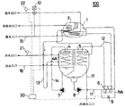
本発明の第1の実施例を、図1〜図3に基づいて説明する。図1に例示した吸収冷凍機100は、図示しない熱負荷にブラインとしての冷水を循環供給することが可能な低温水吸収冷凍機であり、冷媒に水を、吸収液に臭化リチウム(LiBr)水溶液を使用するものである。なお、理解を容易にするため、これらの図においても前記図4において説明した部分と同様の機能を有する部分には、同一の符号を付した。
A first embodiment of the present invention will be described with reference to FIGS. The
すなわち、図中1は再生器、3は凝縮器、4は蒸発器、5は吸収器、6は熱交換器、7は冷媒ポンプ、8は吸収液ポンプ、9は開閉弁、10は三方弁、11、12は吸収液管、11Aはバイパス管、13、14は冷媒管、15はコ・ジェネレーションシステムなどの他の設備から供給される排熱流体が内部を流れる排熱流体供給管、16は図示しない冷却負荷に循環供給する冷水が内部を流れる冷水管、17は冷却水が内部を流れる冷却水管であり、それぞれ図1に示したように配管接続されている。 1 is a regenerator, 3 is a condenser, 4 is an evaporator, 5 is an absorber, 6 is a heat exchanger, 7 is a refrigerant pump, 8 is an absorption liquid pump, 9 is an on-off valve, and 10 is a three-way valve. , 11 and 12 are absorption liquid pipes, 11A is a bypass pipe, 13 and 14 are refrigerant pipes, 15 is a waste heat fluid supply pipe through which waste heat fluid supplied from other equipment such as a cogeneration system flows, 16 Is a chilled water pipe through which chilled water that is circulated and supplied to a cooling load (not shown) flows, and 17 is a chilled water pipe through which the chilled water flows and are connected to each other as shown in FIG.
また、30は、冷水管16の蒸発器出口側に設けられた温度センサ21が計測する冷水の温度に基づいて開閉弁9の開閉を制御し、排熱流体供給管15の三方弁下流側に設けられた温度センサ22が計測する排熱流体の温度に基づいて三方弁10の流路を制御するための制御器である。
Further, 30 controls the opening / closing of the open /
上記構成の本発明の吸収冷凍機100においては、冷却水管17を介して吸収器5と凝縮器3に冷却水を供給し、再生器1に排熱流体供給管15を介してコ・ジェネレーションシステムなどの図示しない他の設備から出る高温の排熱流体、例えば温水を供給すると、稀吸収液から蒸発分離した冷媒蒸気と、冷媒蒸気を分離して再生され、吸収液濃度が高くなった濃吸収液とが再生器1で得られる。
In the
再生器1で吸収液から蒸発分離して生成された高温の冷媒蒸気は、再生器1に並設された凝縮器3に入り、冷却水管17内を流れる冷却水により冷却されて凝縮し、冷媒管13を介して蒸発器4に入る。
The high-temperature refrigerant vapor generated by evaporating and separating from the absorption liquid in the regenerator 1 enters the
蒸発器4に入って冷媒液溜りに溜まった冷媒液は、冷水管16に接続された伝熱管4Aの上に冷媒ポンプ7によって散布され、冷水管16を介して供給される水と熱交換して蒸発し、伝熱管4Aの内部を流れる水を冷却する。
The refrigerant liquid that has entered the evaporator 4 and accumulated in the refrigerant liquid reservoir is sprayed by the
蒸発器4で蒸発した冷媒は吸収器5に入り、再生器1で温水により加熱されて冷媒を蒸発分離し、吸収液濃度が高まった吸収液、すなわち吸収液管12により熱交換器6を経由して供給され、上方から散布される濃吸収液に吸収される。
The refrigerant evaporated in the evaporator 4 enters the
吸収器5で冷媒を吸収して濃度の薄くなった吸収液、すなわち稀吸収液は吸収液ポンプ8の運転により、熱交換器6を経由して再生器1へ吸収液管11から送られる。
The absorption liquid whose concentration has been reduced by absorbing the refrigerant in the
上記のように吸収冷凍機100の運転が行われると、蒸発器4の内部に配管された伝熱管4Aにおいて冷媒の気化熱によって冷却された冷水が、冷水管16を介して図示しない冷房負荷に循環供給できるので、冷房などの冷却運転が行える。
When the
そして、本発明の吸収冷凍機100においては、その冷却運転時に温度センサ22が計測する排熱流体の温度が所定の設定温度、例えば70±0.5℃に収まるように、三方弁10の流路が制御手段30により制御される。
In the
すなわち、例えば図2に示したように、温度センサ22が計測する排熱流体の温度が70.5℃より高いときには三方弁10を開弁し(排熱流体が再生器1を経由して流れる流路状態を開弁とし、再生器1を経由しないで流れる流路状態を閉弁とする。)、69.5℃より低いときには三方弁10を閉弁するように制御手段30により制御される。
That is, for example, as shown in FIG. 2, when the temperature of the exhaust heat fluid measured by the
さらに、温度センサ21が計測する冷水の温度が所定の設定温度、例えば7±0.5℃の範囲に収まるように、開閉弁9の開閉が制御手段30により制御される。すなわち、例えば図3に示したように温度センサ21が計測する冷水の温度が7.5℃より高いときには開閉弁9を閉弁し、6.5℃より低いときには開閉弁9を開弁するように制御される。
Further, the opening /
したがって、例えば冷房負荷が小さいために冷水管16を介して蒸発器4に還流する冷水の温度が低く、冷媒が蒸発する際に周囲から奪う気化熱により冷却されて蒸発器4から吐出し、温度センサ21により計測される冷水の温度が所定の6.5℃より低くなると、開閉弁9が開弁して吸収器5からバイパス管11Aを経由して再生器1に流入する吸収液の流れが生じ、熱交換器6で加熱されて再生器1に流入する量が減少するので、吸収器5から再生器1に流入する吸収液全体の温度は低下する。
Therefore, for example, since the cooling load is small, the temperature of the cold water recirculated to the evaporator 4 through the
したがって、排熱流体供給管15を介して再生器1に供給され、そこで吸収液を加熱して冷媒を蒸発分離し、吸収液を再生して再生器1から吐出する排熱流体の温度も低下するので、温度センサ22が計測する排熱流体の温度も低下する。そのため、三方弁10は制御手段30により開弁され、再生器1で吸収液を加熱して放熱する熱量が増加する。
Therefore, the heat is supplied to the regenerator 1 via the exhaust heat
すなわち、本発明の吸収冷凍機100においては、熱交換器6を迂回して吸収器5から再生器1に流入する吸収液の量を増加させて全体の熱効率を低下させることで、排熱流体が再生器1で放熱する熱量を増やすことができるので、冷水管16を介して冷水を循環供給する熱負荷が小さいために排熱流体供給管15を介して供給される排熱流体の再生器1における放熱量が小さく、温度センサ22が計測する排熱流体の温度が所定温度の70.5℃より高いときには、開閉弁9が開弁して吸収器5から熱交換器6を迂回して再生器1に流入する吸収液の量を増加させて熱効率を低下させることで、温度センサ22が計測する排熱流体の温度を所定の温度範囲まで低下させることができる。
That is, in the
なお、本発明は上記実施形態に限定されるものではないので、特許請求の範囲に記載の趣旨から逸脱しない範囲で各種の変形実施が可能である。 In addition, since this invention is not limited to the said embodiment, various deformation | transformation implementation is possible in the range which does not deviate from the meaning as described in a claim.
例えば、バイパス管11Aに介在する開閉弁9は、開閉弁ではなく流量制御弁であっても良い。そして、開閉弁に代えて流量制御弁をバイパス管11Aに設けるときには、温度センサ21が計測する冷水の温度が所定の温度(例えば7℃)となるように、制御器30が流量制御弁の開度を制御するように構成される。
For example, the on-off
また、開閉弁9を備えたバイパス管11Aは、再生器1から吸収器5に流入する吸収液の一部が熱交換器6を迂回して流れるように吸収液管12に設けられても良い。
Further, the bypass pipe 11 </ b> A provided with the opening /
また、特許文献1に開示された吸収冷凍機のように、高温再生器と低温再生器、高温熱交換器と低温熱交換器を備えた吸収冷凍機であっても良い。 Moreover, the absorption refrigerator provided with the high temperature regenerator and the low temperature regenerator, the high temperature heat exchanger, and the low temperature heat exchanger like the absorption refrigerator disclosed by patent document 1 may be sufficient.
また、三方弁10に代えて開閉弁または流量制御弁を排熱流体供給管15の適宜の部位に設けるように構成することも可能である。
Further, it is possible to provide an open / close valve or a flow control valve in place of the three-way valve 10 at an appropriate portion of the exhaust heat
1 再生器
3 凝縮器
4 蒸発器
4A 伝熱管
5 吸収器
6 熱交換器
7 冷媒ポンプ
8 吸収液ポンプ
9 開閉弁
10 三方弁
11、12 吸収液管
11A バイパス管
13、14 冷媒管
15 排熱流体供給管
16 冷水管
17 冷却水管
21、22 温度センサ
30 制御器
35 放熱器
100、100X 吸収冷凍機
DESCRIPTION OF SYMBOLS 1
Claims (2)
Priority Applications (1)
| Application Number | Priority Date | Filing Date | Title |
|---|---|---|---|
| JP2004145012A JP2005326089A (en) | 2004-05-14 | 2004-05-14 | Absorption refrigerating machine |
Applications Claiming Priority (1)
| Application Number | Priority Date | Filing Date | Title |
|---|---|---|---|
| JP2004145012A JP2005326089A (en) | 2004-05-14 | 2004-05-14 | Absorption refrigerating machine |
Publications (1)
| Publication Number | Publication Date |
|---|---|
| JP2005326089A true JP2005326089A (en) | 2005-11-24 |
Family
ID=35472571
Family Applications (1)
| Application Number | Title | Priority Date | Filing Date |
|---|---|---|---|
| JP2004145012A Pending JP2005326089A (en) | 2004-05-14 | 2004-05-14 | Absorption refrigerating machine |
Country Status (1)
| Country | Link |
|---|---|
| JP (1) | JP2005326089A (en) |
Cited By (1)
| Publication number | Priority date | Publication date | Assignee | Title |
|---|---|---|---|---|
| JP2013032908A (en) * | 2012-11-15 | 2013-02-14 | Ebara Refrigeration Equipment & Systems Co Ltd | Absorption refrigerating machine |
-
2004
- 2004-05-14 JP JP2004145012A patent/JP2005326089A/en active Pending
Cited By (1)
| Publication number | Priority date | Publication date | Assignee | Title |
|---|---|---|---|---|
| JP2013032908A (en) * | 2012-11-15 | 2013-02-14 | Ebara Refrigeration Equipment & Systems Co Ltd | Absorption refrigerating machine |
Similar Documents
| Publication | Publication Date | Title |
|---|---|---|
| JP3883838B2 (en) | Absorption refrigerator | |
| JP2011089722A (en) | Method and device for refrigeration/air conditioning | |
| JP2002147885A (en) | Absorption refrigerating machine | |
| JP2015048987A (en) | Air conditioner | |
| JP2005009754A (en) | Single/double effect absorption refrigerating machine, and its operation control method | |
| JP5261111B2 (en) | Absorption refrigerator | |
| JP3883894B2 (en) | Absorption refrigerator | |
| JP4315854B2 (en) | Absorption refrigerator | |
| JP2005326089A (en) | Absorption refrigerating machine | |
| JP4315855B2 (en) | Absorption refrigerator | |
| JP4079570B2 (en) | Control method of absorption refrigerator | |
| JP4330522B2 (en) | Absorption refrigerator operation control method | |
| JP2007333342A (en) | Multi-effect absorption refrigerating machine | |
| JP3851204B2 (en) | Absorption refrigerator | |
| JP4308076B2 (en) | Absorption refrigerator | |
| JP3729102B2 (en) | Steam-driven double-effect absorption chiller / heater | |
| JP4315697B2 (en) | Absorption chiller / heater | |
| JP2001208443A (en) | Absorption freezer | |
| JP2005106408A (en) | Absorption type freezer | |
| JP3857955B2 (en) | Absorption refrigerator | |
| JP3811632B2 (en) | Waste heat input type absorption refrigerator | |
| JP3143251B2 (en) | Absorption refrigerator | |
| JP2020046128A (en) | Absorption refrigerator | |
| JP2017036856A (en) | Waste heat input type absorption chiller heater and waste heat recovery amount control method thereof | |
| JP2895974B2 (en) | Absorption refrigerator |
Legal Events
| Date | Code | Title | Description |
|---|---|---|---|
| A621 | Written request for application examination |
Free format text: JAPANESE INTERMEDIATE CODE: A621 Effective date: 20070509 |
|
| A977 | Report on retrieval |
Free format text: JAPANESE INTERMEDIATE CODE: A971007 Effective date: 20081112 |
|
| A131 | Notification of reasons for refusal |
Free format text: JAPANESE INTERMEDIATE CODE: A131 Effective date: 20081118 |
|
| A521 | Written amendment |
Free format text: JAPANESE INTERMEDIATE CODE: A523 Effective date: 20090115 |
|
| A131 | Notification of reasons for refusal |
Free format text: JAPANESE INTERMEDIATE CODE: A131 Effective date: 20090407 |
|
| A02 | Decision of refusal |
Free format text: JAPANESE INTERMEDIATE CODE: A02 Effective date: 20090929 |