JP2005310941A - Spin coater and method of cleaning cup thereof, and brush jig for cleaning cup - Google Patents
Spin coater and method of cleaning cup thereof, and brush jig for cleaning cup Download PDFInfo
- Publication number
- JP2005310941A JP2005310941A JP2004123833A JP2004123833A JP2005310941A JP 2005310941 A JP2005310941 A JP 2005310941A JP 2004123833 A JP2004123833 A JP 2004123833A JP 2004123833 A JP2004123833 A JP 2004123833A JP 2005310941 A JP2005310941 A JP 2005310941A
- Authority
- JP
- Japan
- Prior art keywords
- cup
- rotary stage
- brush
- spin coater
- wall
- Prior art date
- Legal status (The legal status is an assumption and is not a legal conclusion. Google has not performed a legal analysis and makes no representation as to the accuracy of the status listed.)
- Pending
Links
- 238000004140 cleaning Methods 0.000 title claims abstract description 101
- 238000000034 method Methods 0.000 title claims abstract description 33
- 239000007788 liquid Substances 0.000 claims abstract description 51
- 238000005406 washing Methods 0.000 claims abstract description 6
- 239000000758 substrate Substances 0.000 claims description 9
- 239000007787 solid Substances 0.000 description 26
- 239000003960 organic solvent Substances 0.000 description 6
- 238000005086 pumping Methods 0.000 description 6
- 238000010586 diagram Methods 0.000 description 5
- XLYOFNOQVPJJNP-UHFFFAOYSA-N water Substances O XLYOFNOQVPJJNP-UHFFFAOYSA-N 0.000 description 5
- CBENFWSGALASAD-UHFFFAOYSA-N Ozone Chemical compound [O-][O+]=O CBENFWSGALASAD-UHFFFAOYSA-N 0.000 description 4
- 238000000576 coating method Methods 0.000 description 4
- 230000001680 brushing effect Effects 0.000 description 3
- 238000007599 discharging Methods 0.000 description 3
- 210000004209 hair Anatomy 0.000 description 3
- 239000003595 mist Substances 0.000 description 3
- 229920003023 plastic Polymers 0.000 description 3
- 239000004033 plastic Substances 0.000 description 3
- XUIMIQQOPSSXEZ-UHFFFAOYSA-N Silicon Chemical compound [Si] XUIMIQQOPSSXEZ-UHFFFAOYSA-N 0.000 description 2
- 238000011109 contamination Methods 0.000 description 2
- 238000000206 photolithography Methods 0.000 description 2
- 229910052710 silicon Inorganic materials 0.000 description 2
- 239000010703 silicon Substances 0.000 description 2
- 239000002904 solvent Substances 0.000 description 2
- LFQSCWFLJHTTHZ-UHFFFAOYSA-N Ethanol Chemical compound CCO LFQSCWFLJHTTHZ-UHFFFAOYSA-N 0.000 description 1
- 229910004298 SiO 2 Inorganic materials 0.000 description 1
- 230000015572 biosynthetic process Effects 0.000 description 1
- 239000011248 coating agent Substances 0.000 description 1
- 238000007796 conventional method Methods 0.000 description 1
- 238000004090 dissolution Methods 0.000 description 1
- 230000005611 electricity Effects 0.000 description 1
- 229920002457 flexible plastic Polymers 0.000 description 1
- 239000012212 insulator Substances 0.000 description 1
- 238000012423 maintenance Methods 0.000 description 1
- 238000004519 manufacturing process Methods 0.000 description 1
- 239000000463 material Substances 0.000 description 1
- 239000002184 metal Substances 0.000 description 1
- 239000000203 mixture Substances 0.000 description 1
- 239000002245 particle Substances 0.000 description 1
- 230000002093 peripheral effect Effects 0.000 description 1
- 238000012545 processing Methods 0.000 description 1
- 239000004065 semiconductor Substances 0.000 description 1
- 230000003068 static effect Effects 0.000 description 1
- 239000012209 synthetic fiber Substances 0.000 description 1
- 229920002994 synthetic fiber Polymers 0.000 description 1
- 238000012546 transfer Methods 0.000 description 1
- 238000011282 treatment Methods 0.000 description 1
Images


Abstract
Description
本発明は、スピンコータのカップ洗浄方法及びスピンコータ、並びに、カップ洗浄用のブラシ治具に関し、特に、レジスト膜や、SOG膜を形成するためのスピンコータにおけるカップ洗浄技術に関するものである。 The present invention relates to a spin coater cup cleaning method, a spin coater, and a brush jig for cup cleaning, and more particularly to a cup cleaning technique in a spin coater for forming a resist film and an SOG film.
従来から、半導体装置の製造工程では、ウエーハ上に回路パターンを転写するためにフォトリソグラフィ技術が用いられている。このフォトリソグラフィ技術では、ウエーハの表面上にレジスト液を滴下し、滴下したレジスト液を遠心力で拡散させることによって、このウエーハの表面上にレジスト液を均一な厚さに塗布するスピンコータ(液体塗布装置とも呼ばれる。)が多用されている。 Conventionally, in the manufacturing process of a semiconductor device, a photolithography technique is used to transfer a circuit pattern onto a wafer. In this photolithography technique, a spin coater (liquid coating) is applied to apply a resist solution to a uniform thickness on the surface of the wafer by dropping the resist solution on the surface of the wafer and diffusing the dropped resist solution by centrifugal force. Is often used as a device).
この種のスピンコータでは、ウエーハの回転に伴ってレジスト液は周囲へ飛散する。飛散したレジスト液は、カップの内壁に付着し、その自重によってカップの底面にあるドレーンへ流れ落ちる。そして、流れ落ちたレジスト液はこのドレーンからスピンコータの外へ排出される構造となっている。また、レジスト液をウエーハの表面上に塗布する際に特に細かく飛び散った霧状のレジスト(以下、「ミスト」という。)は、このカップ内を流れる空気に乗ってカップの底面に移動し、このカップの底面にある排気口からスピンコータの外へ排出される構造となっている。 In this type of spin coater, the resist solution scatters to the surroundings as the wafer rotates. The scattered resist solution adheres to the inner wall of the cup and flows down to the drain on the bottom surface of the cup by its own weight. The resist solution that has flowed down is discharged from the drain to the outside of the spin coater. Further, when the resist solution is applied onto the surface of the wafer, the mist-like resist (hereinafter referred to as “mist”) that has been scattered finely moves on the air flowing in the cup and moves to the bottom surface of the cup. It is structured to be discharged out of the spin coater through the exhaust port on the bottom of the cup.
このような構造のスピンコータを用いてレジスト液の塗布処理を行うと、その処理回数が増えるに従って、カップの内壁にレジスト液やミストが付着して固形化、又は半固形化してしまう。そして、レジスト液の塗布処理回数が累積されるに従って、レジストの固形物や半固形物(以下、「固形物等」という。)はカップの内壁に堆積していく。
ところで、このような固形物等はカップ内で、パーティクルの発生源となることが知られている。それゆえ、従来から、カップの内壁に固形物等がある程度堆積した時点で、スピンコータによるレジスト塗布処理を止め、カップの内壁を洗浄して固形物等を除去する必要(即ち、メンテナンスとして、カップの内壁を定期的に洗浄する必要)があった。このようなカップの洗浄方法としては、例えば、下記のi)、又はii)等が挙げられる。
When a resist solution is applied using a spin coater having such a structure, the resist solution and mist adhere to the inner wall of the cup and become solid or semi-solid as the number of treatments increases. Then, as the number of times the resist solution is applied, the resist solids and semi-solids (hereinafter referred to as “solids”) accumulate on the inner wall of the cup.
By the way, it is known that such solids and the like become a generation source of particles in the cup. Therefore, conventionally, when solid matter or the like has accumulated to some extent on the inner wall of the cup, it is necessary to stop the resist coating process by the spin coater and to wash the inner wall of the cup to remove the solid matter (that is, as maintenance of the cup) It was necessary to clean the inner wall regularly). Examples of such a cup cleaning method include the following i) or ii).
i)まず始めに、手作業でカップをスピンコータから取り外す。次に、取り外したカップを、有機溶剤等が準備されたドラフト内に移動させる。そして、このドラフト内でカップを有機溶材等に浸漬し、一定時間放置して固形物等を溶解させる。さらに、固形物等の溶解除去が不十分な場合には、同ドラフト内でカップの内壁をブラシ等で擦り洗いする。これにより、カップの内壁から固形物等を完全に取り除く。 i) First, remove the cup from the spin coater by hand. Next, the removed cup is moved into a draft prepared with an organic solvent or the like. Then, the cup is immersed in an organic solvent or the like in the draft, and left for a certain period of time to dissolve solids or the like. Furthermore, when the dissolution and removal of solids or the like is insufficient, the inner wall of the cup is scrubbed with a brush or the like in the same draft. Thereby, solids etc. are completely removed from the inner wall of the cup.
ii)予め、スピンコータにオゾン水の供給系を設けておく。そして、洗浄周期がくる毎にレジスト液の塗布処理を止め、スピンコータにカップを取り付けたままの状態で、このカップの内壁にオゾン水を吹き付ける。これにより、カップの内壁に付着していた固形物等を溶解除去する(例えば、特許文献1参照。)。
ところで、上記i)の洗浄方法によれば、カップを洗浄する際に、手作業でスピンコータからカップを取り外す必要があった。また、取り外したスピンコータをドラフト内まで運ぶ必要があり、場合によっては、手作業でカップの内壁を擦り洗いする必要があった。そのため、カップの洗浄に手間がかかり、作業者の負荷が大きいという問題があった。
また、上記ii)の洗浄方法によれば、カップを取り外す必要がなく、しかもカップを自動で洗浄することが可能なので、上記i)の方法と比べて、作業者の負荷が小さくて済むという利点がある。しかしながら、その一方で、塗布処理に用いたレジストの粘性が極めて高いような場合、或いは、カップの内壁に大量の固形物等がしつこく、こびり付くように付着しているような場合には、上記ii)の方法では、固形物等を十分に除去できない可能性があり、カップ内壁の洗浄が不十分となってしまう可能性があった。
By the way, according to the cleaning method of i), when the cup was cleaned, it was necessary to manually remove the cup from the spin coater. Further, it is necessary to carry the removed spin coater into the draft, and in some cases, it is necessary to manually wash the inner wall of the cup. Therefore, there is a problem that it takes time to clean the cup and the load on the operator is large.
Further, according to the cleaning method of ii), it is not necessary to remove the cup, and the cup can be automatically cleaned, so that the burden on the operator can be reduced compared with the method of i). There is. However, on the other hand, when the viscosity of the resist used for the coating process is extremely high, or when a large amount of solids are persistently adhered to the inner wall of the cup, In the method ii), solids and the like may not be sufficiently removed, and the cup inner wall may not be sufficiently cleaned.
本発明は、このような従来の技術の有する未解決の課題に着目してなされたものであって、スピンコータのカップの内壁を簡単、かつ効果的に洗浄できるようにしたスピンコータのカップ洗浄方法及びスピンコータ、並びに、カップ洗浄用のブラシ治具の提供を目的とする。 The present invention has been made paying attention to such an unsolved problem of the conventional technique, and a spin coater cup cleaning method capable of easily and effectively cleaning the inner wall of a spin coater cup and An object is to provide a spin coater and a brush jig for cleaning a cup.
〔発明1〕 上記目的を達成するために、発明1のスピンコータのカップ洗浄方法は、基板の裏面を回転可能に支持する回転ステージと、前記回転ステージをその側方から囲むカップとを備えたスピンコータのカップ洗浄方法であって、前記回転ステージにブラシ治具を固定する工程と、前記カップの内壁に所定の洗浄液を供給する工程と、前記ブラシを前記カップの内壁に接触させた状態で前記回転ステージを回転させる工程と、を含むことを特徴とするものである。 [Invention 1] In order to achieve the above object, a spin coater cup cleaning method of Invention 1 includes a rotation stage that rotatably supports a back surface of a substrate, and a cup that surrounds the rotation stage from its side. A cup cleaning method, a step of fixing a brush jig to the rotary stage, a step of supplying a predetermined cleaning liquid to the inner wall of the cup, and the rotation with the brush in contact with the inner wall of the cup And a step of rotating the stage.
ここで、液体とは、例えばレジスト液や、SOG形成用の液体(SiO2をアルコール等の有機溶媒に溶かした液)である。これらの液体は、水と比べて高い粘性を有し、又、溶媒分が揮発し易いので、カップの内壁に一度付着するとそのまま固まって、カップ内に固形物、又は半固形物(以下、「固形物等」という。)として残留しやすい。また、洗浄液とは、例えば、レジストに対して溶解能をもつ有機溶剤や、オゾン水等である。 Here, the liquid is, for example, a resist solution or a liquid for forming SOG (a solution in which SiO 2 is dissolved in an organic solvent such as alcohol). These liquids have a higher viscosity than water, and the solvent component easily volatilizes. Therefore, once the liquid adheres to the inner wall of the cup, it solidifies as it is, and a solid or semi-solid (hereinafter, “ It is easy to remain as “solids”. In addition, the cleaning liquid is, for example, an organic solvent having a dissolving ability with respect to a resist, ozone water, or the like.
発明1のスピンコータのカップ洗浄方法によれば、所定の洗浄液が施されたカップの内壁を、回転ステージの回転動作を利用してブラッシングすることが可能である。従って、スピンコータのカップの内壁を簡単、かつ効果的に洗浄することができる。 According to the spin coater cup cleaning method of the first aspect of the present invention, it is possible to brush the inner wall of the cup on which a predetermined cleaning liquid has been applied, using the rotating operation of the rotary stage. Therefore, the inner wall of the spin coater cup can be cleaned easily and effectively.
例えば、レジストの固形物等が付着しているカップの内壁に洗浄液を施しながら、回転ステージの回転動作を利用してこのカップの内壁を自動でブラッシングすることができる。これにより、カップの内壁を洗浄する際に、作業者はこのカップをスピンコータから外さなくても済み、作業者の作業負荷を軽減することができる。また、洗浄液を施しながらのブラッシングによりレジストの固形物等を溶解しながら擦り落とすことができるので、カップの内壁を効果的に洗浄することができる。これにより、洗浄後のレジスト残りを少なくすることができ、レジスト残りによるウエーハの汚染を少なくすることができる。製品の歩留り向上に貢献することができる。 For example, the inner wall of the cup can be automatically brushed using the rotating operation of the rotary stage while applying a cleaning liquid to the inner wall of the cup to which the resist solid or the like is adhered. Thus, when cleaning the inner wall of the cup, the operator does not have to remove the cup from the spin coater, and the work load on the operator can be reduced. Further, since the resist solids and the like can be scraped off by brushing while applying the cleaning liquid, the inner wall of the cup can be effectively cleaned. As a result, the resist residue after cleaning can be reduced, and contamination of the wafer due to the resist residue can be reduced. It can contribute to the improvement of product yield.
〔発明2〕 発明2のスピンコータのカップ洗浄方法は、発明1のスピンコータのカップ洗浄方法において、前記ブラシを前記カップの内壁に接触させた状態で、前記回転ステージ又は前記カップの少なくとも一方を当該回転ステージの回転面に対して鉛直方向に移動させる工程と、を含むことを特徴とするものである。このような構成であれば、発明1のスピンコータのカップ洗浄方法と比べて、カップの内壁をより広範囲にブラッシングすることが可能である。 [Invention 2] The spin coater cup cleaning method of Invention 2 is the spin coater cup cleaning method of Invention 1, wherein at least one of the rotary stage and the cup is rotated in a state where the brush is in contact with the inner wall of the cup. And a step of moving in a vertical direction with respect to the rotation surface of the stage. With such a configuration, it is possible to brush the inner wall of the cup in a wider range compared to the cup cleaning method of the spin coater of the first aspect.
〔発明3〕 発明3のスピンコータのカップ洗浄方法は、発明2のスピンコータのカップ洗浄方法において、前記ブラシを前記カップの内壁に接触させた状態で前記回転ステージを回転させる工程と、前記回転ステージ又は前記カップの少なくとも一方を当該回転ステージの回転面に対して鉛直方向に移動させる工程と、を同時に行うことを特徴とするものである。このような構成であれば、発明2のスピンコータのカップ洗浄方法と比べて、カップの洗浄時間の短縮が可能である。 [Invention 3] The spin coater cup cleaning method of Invention 3 is the spin coater cup cleaning method of Invention 2, wherein the rotating stage is rotated while the brush is in contact with the inner wall of the cup; And a step of moving at least one of the cups in a vertical direction with respect to a rotation surface of the rotary stage. With such a configuration, the cleaning time of the cup can be shortened as compared with the cup cleaning method of the spin coater of the second aspect.
〔発明4〕 発明4のスピンコータは、前記基板の裏面を回転可能に支持する回転ステージと、前記回転ステージをその側方から囲むカップと、前記カップの内壁に所定の洗浄液を供給する洗浄液供給手段と、前記回転ステージに固定されるブラシ治具と、を備えたことを特徴とするものである。 [Invention 4] The spin coater of Invention 4 includes a rotation stage that rotatably supports the back surface of the substrate, a cup that surrounds the rotation stage from its side, and a cleaning liquid supply means that supplies a predetermined cleaning liquid to the inner wall of the cup. And a brush jig fixed to the rotary stage.
発明4のスピンコータによれば、カップの内壁に所定の洗浄液を供給し、回転ステージに固定されたブラシ治具のブラシをカップの内壁に接触させた状態で当該回転ステージを回転させることが可能である。従って、回転ステージの回転動作を利用してカップの内壁をブラッシングすることが可能であり、スピンコータのカップの内壁を簡単、かつ効果的に洗浄することができる。 According to the spin coater of the invention 4, it is possible to supply a predetermined cleaning liquid to the inner wall of the cup and rotate the rotary stage in a state where the brush of the brush jig fixed to the rotary stage is in contact with the inner wall of the cup. is there. Therefore, it is possible to brush the inner wall of the cup by utilizing the rotational operation of the rotary stage, and it is possible to clean the inner wall of the spin coater cup easily and effectively.
〔発明5〕 発明5のブラシ治具は、発明1のスピンコータのカップ洗浄方法に適用可能なブラシ治具であって、前記回転ステージ上に固定可能な円盤状の基体と、前記基体の側面に取り付けられたブラシと、を有することを特徴とするものである。 [Invention 5] The brush jig of Invention 5 is a brush jig applicable to the spin coater cup cleaning method of Invention 1, wherein the brush jig is fixed on the rotary stage, and is mounted on the side surface of the substrate. And an attached brush.
発明5のカップ洗浄用のブラシ治具によれば、スピンコータのカップの内壁を簡単、かつ効果的に洗浄することができる。 According to the brush jig for cleaning a cup of the invention 5, the inner wall of the cup of the spin coater can be cleaned easily and effectively.
以下、図面を参照しながら、本発明に係るスピンコータのカップ洗浄方法及びスピンコータ、並びに、カップ洗浄用のブラシ治具について説明する。
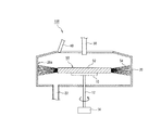
図1は、本発明の実施形態に係るスピンコータ100の構成例を示す概念図である。このスピンコータ100は、ウエーハW上にレジスト液を滴下し当該ウエーハWを高速回転させ、このウエーハW上に薄いレジスト膜を形成する装置である。このウエーハWは、例えばシリコンウエーハ、SOI(silicon on insulator)ウエーハ等である。図1に示すように、スピンコータ100は、回転ステージ10と、カップ20と、レジスト吐出ノズル30と、洗浄液吐出ノズル40等から構成されている。
Hereinafter, a cup coater cleaning method and spin coater according to the present invention, and a brush jig for cup cleaning will be described with reference to the drawings.
FIG. 1 is a conceptual diagram showing a configuration example of a
これらの中で、回転ステージ10は、ウエーハWの裏面を回転可能に支持するものである。この回転ステージ10のウエーハWの裏面と接触する面(以下、「接触面」という。)には、一つ若しくは多数の孔が設けられている。これら多数の孔は、真空ポンプ(図示せず)に接続されている。ウエーハWを回転ステージ10上に載置した状態で、これらの孔を通して真空引きすると、ウエーハWの裏面は回転ステージ10の接触面に吸着されて固定される。
Among these, the
また、回転軸12を自転させるモータによって、回転ステージ10はその接触面の中心を通る鉛直線回りに回転可能となっている。このような構成により、回転ステージ10の接触面の中心と、ウエーハWの中心とを重ね合わせるようにして、この回転ステージ10上にウエーハWを載置することで、ウエーハWをその表面の中心を通る鉛直線回りに回転させることができる。この回転ステージ10は、例えば平面視で円形であり、その直径は例えば80[mm]程度である。
Further, the
図1に示すように、カップ20は回転ステージ10を内側に収容し、回転ステージ10をその側方から包み囲む容器である。このカップ20の底面の中心部には、回転ステージ10の回転軸12を通すための開口部が設けられている。また、このカップ20は、その内側の直径が回転ステージ10やウエーハWの直径よりも大きくされている。このような構成により、カップ20内でウエーハWをその表面の中心を通る鉛直線回りに回転させることができる。
As shown in FIG. 1, the
図1に示すように、このカップ20の底面には、レジスト液や洗浄液等を排出するためのドレーン22が設けられている。また、図示しないが、このカップの底面には、カップ内の雰囲気や、レジスト液をウエーハの表面上に塗布する際に特に細かく飛び散った霧状のレジスト(ミスト)等をスピンコータの外へ排出するための排気口が設けられている。このカップ20の内側の直径は、例えば250[mm]程度である。また、このカップ20は、例えばプラスチック製である。
As shown in FIG. 1, a
図1に示すように、レジスト吐出ノズル30は、その先端部に吐出口を有し、その後端部がレジスト液圧送部(図示せず)に接続されている。このレジスト吐出ノズル30は、例えば半透明のゴム製、または柔軟性を有するプラスチック製の管部材である。このレジスト吐出ノズル30の吐出口は、回転ステージ10の接触面の中心部上方にくるように、その位置が調整されている。レジスト液は、レジスト液圧送部の圧送動作によって、レジスト吐出ノズル30を通って吐出口まで圧送され、吐出口から滴下される。従って、ウエーハWを回転ステージ10上に載置した場合に、このウエーハWの表面の中心部上にレジスト液が滴下される。
As shown in FIG. 1, the resist
このスピンコータ100では、回転ステージ10を例えば毎分10〜6000回転のうち任意の速度で回転させる。これにより、このウエーハWの表面上に滴下されたレジスト液を遠心力で拡散させて、ウエーハWの表面上にレジスト液を均一な厚さに塗布する。一方、このようなレジスト液の塗布の過程で、ウエーハWの表面上に膜として残らないレジスト液(即ち、レジスト液の余り)は遠心力によってウエーハWの周縁からカップ20の内壁方向や、底面方向に飛ばされる。そして、このようにして飛ばされたレジスト液の一部は、ドレーン22に到達する前に溶媒分を失い、カップ20内で固形化、又は半固形化してしまう。
In the
図1に示すように、洗浄液吐出ノズル40は、その先端部に吐出口を有し、その後端部が洗浄液圧送部(図示せず)に接続されている。この洗浄液吐出ノズル40は、例えば金属製、半透明のゴム製、または柔軟性を有するプラスチック製の管部材である。この洗浄液吐出ノズル40の吐出口はカップ20内に向けられている。洗浄液は、洗浄液圧送部の圧送動作によって、洗浄液吐出ノズル40を通って吐出口まで圧送され、吐出口から吐出される。
As shown in FIG. 1, the cleaning
図2(A)及び(B)は本発明の実施形態に係る洗浄ブラシ50の構成例を示す平面図と、X−X´矢視断面図である。
図2(A)に示すように、この洗浄ブラシ50は、基体52と、ブラシ54(即ち、刷毛)と、から構成されている。基体52は、例えば所定の厚みを有し、平面視での形状は例えば円形である(即ち、円盤状である。)。一例を挙げると、円盤状の基体52の直径は例えば150[mm]程度であり、その厚みは例えば10[mm]程度である。この基体52は、例えばプラスチック製である。
2A and 2B are a plan view illustrating a configuration example of the cleaning
As shown in FIG. 2A, the cleaning
回転ステージ10で洗浄ブラシ50を吸着し固定することができるように、また、洗浄ブラシ50がカップ20の内側に入るように、洗浄ブラシ50の基体52の大きさは回転ステージ10の直径と、カップ20の内径等に合わせて調整されている。
また、図2(B)に示すように、ブラシ54は、基体52の側面に取り付けられている。このブラシ54は、例えば合成繊維からなる多数の「毛」からなるものである。出来れば静電気の付きにくい材質のほうが望ましい。この「毛」の基体52側面の付け根から、その先端部までの長さは例えば50〜60mm]程度である。カップ20の内側で回転ステージ10上に洗浄ブラシ50を配置した際に、洗浄ブラシ50のブラシ54の先端部がカップ20の内壁20aと十分接触することができるように、ブラシ54を構成する「毛」の長さは調整されている。
The size of the
2B, the
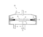
図3は、本発明の実施形態に係るカップ20の洗浄方法を示す概念図である。ここでは、スピンコータ100を用いてレジスト液の塗布処理を繰り返し行い、その結果、カップ20の内壁20aにレジスト液が付着して固形化、又は半固形化している場合を想定する。
まず、始めに、スピンコータ100からウエーハWをアンロードさせる(即ち、スピンコータ100での製品処理を終了させる。)。次に、カップ20の内側にある回転ステージ10の接触面の中心と、洗浄ブラシ50の基体52の中心とを重ね合わせるようにして、この回転ステージ10上に基体52を載置する。そして、この回転ステージ10上に洗浄ブラシ50の基体52を吸着固定させる。
FIG. 3 is a conceptual diagram showing a method for cleaning the
First, the wafer W is unloaded from the spin coater 100 (that is, the product processing in the
次に、カップ20の内側で回転ステージ10上に吸着固定された洗浄ブラシ50のブラシ54に向けて、洗浄液吐出ノズル40から洗浄液を吐出させる。洗浄液とは、例えば、レジストに対して溶解能をもつ有機溶剤や、オゾン水等である。この実施形態では、洗浄液の一例としてシンナー系の有機溶剤を用いる。
また、この洗浄液の吐出動作と同時に、回転ステージ10をモータにより回転させる。ここでは、回転ステージの回転速度を、一例として毎分1000回転に設定する。この回転動作によって、洗浄ブラシ50に吐出された洗浄液には遠心力が加わり、洗浄液はこの遠心力によってカップ20の内壁20aに飛散する。また、回転ステージ10の回転動作によって、洗浄ブラシ50はそのブラシ54をカップ20の内壁20aに接触させながら回転する。これにより、カップ20の内壁20aに付着していたレジストの固形物や半固形物(固形物等)は洗浄液に溶解されながら、ブラシ54によって擦り落とされる。その後、カップ20の内壁20aからレジストの固形物等が十分除去された後で、回転ステージ10を止める。また、洗浄液吐出ノズル40からの洗浄液の吐出も止める。そして、回転ステージ10上から洗浄ブラシ50を取り出し、カップ20の洗浄作業を終了させる。
Next, the cleaning liquid is discharged from the cleaning
Simultaneously with the discharge operation of the cleaning liquid, the
このように、本発明の実施形態に係るスピンコータ100のカップ20洗浄方法によれば、洗浄液が施されたカップ20の内壁20aを、回転ステージ10の回転動作を利用してブラッシングすることが可能である。従って、スピンコータ100のカップ20の内壁20aを簡単、かつ効果的に洗浄することができる。
即ち、回転ステージ10の回転動作を利用してレジストの固形物等が付着しているカップ20の内壁20aに洗浄液を施すことができ、かつ、回転ステージ10の回転動作を利用してカップ20の内壁20aを自動でブラッシングすることができる。これにより、カップ20の内壁20aを洗浄する際に、作業者はこのカップ20をスピンコータ100から外さなくても済む。それゆえ、作業者の作業負荷を軽減することができる。
Thus, according to the
That is, the cleaning liquid can be applied to the
また、洗浄液を施しながらのブラッシングにより、レジストの固形物等を溶解しながら擦り落とすことができるので、カップの内壁を効果的に洗浄するができる。これにより、洗浄後のレジスト残りを少なくすることができ、レジスト残りによるウエーハWの汚染を少なくすることができる。それゆえ、製品の歩留り向上に貢献することができる。
この実施形態では、洗浄ブラシ50が本発明のブラシ治具に対応し、この洗浄ブラシ50と回転ステージ10と洗浄液供給ノズル40とが本発明の洗浄液供給手段に対応している。また、ウエーハWが本発明の基板に対応し、レジスト液が本発明の液体に対応している。
Further, by brushing while applying the cleaning liquid, it is possible to rub off while dissolving the resist solids and the like, so that the inner wall of the cup can be effectively cleaned. As a result, the resist residue after cleaning can be reduced, and contamination of the wafer W due to the resist residue can be reduced. Therefore, the product yield can be improved.
In this embodiment, the cleaning
なお、この実施形態では、回転ステージ10の回転動作によって、カップ20の内側に洗浄液を施しながらカップ20の内壁20aを自動でブラッシングすることについて説明した。しかしながら、洗浄液の供給動作と、洗浄ブラシ50を吸着固定した状態での回転ステージ10のカップ20内での回転動作とに加えて、回転ステージ10をカップ20内で昇降動作させることによって、カップ20の内壁20aをより広範囲にブラッシングすることが可能である。
In the present embodiment, the description has been given of the automatic brushing of the
例えば、図4において、まず始めに、回転ステージ10をカップ20内で上方向に移動させる。そして、カップ20の内側に洗浄液を供給しながら、回転ステージ10を回転させてカップ20の内壁20aの上段をブラッシングする。次に、回転ステージ10の回転を止め、回転ステージ10をカップ20内で下方向に移動させてその高さを一段下げる。そして、洗浄液を出しながら、回転ステージ10を回転させてカップ20の内壁20aの中段をブラッシングする。次に、回転ステージ10の回転を止め、回転ステージ10をカップ20内で下方向に移動させてその高さをさらに一段下げる。そして、洗浄液を出しながら、回転ステージ10を回転させてカップ20の内壁20aの下段をブラッシングする。このような構成であれば、カップ20の内壁20aをより広範囲にブラッシングすることが可能であり、より広範囲に固形物等を除去することが可能である。
For example, in FIG. 4, first, the
また、例えば、図4において、回転ステージ10のカップ20内での回転動作と、回転ステージ10のカップ20内での昇降動作とを同時に行う構成としても良い。例えば、まず始めに、回転ステージ10をカップ20内で上方向に移動させる。そして、カップ20の内側に洗浄液を供給しながら、回転ステージ10を回転させてカップ20の内壁20aの上段をブラッシングする。また、この回転動作と同時に、回転ステージ10をカップ20内で下方向に少しずつ移動させ、最後にはカップ20の底面付近まで移動させる。そして、回転ステージ10をカップ20の底面付近まで移動させ、一定時間が経過した後で、回転ステージ10の回転動作を止める。このような構成であれば、回転ステージ10の回転動作と昇降動作とを別々に行う場合と比べて、洗浄時間の短縮が可能である。
Further, for example, in FIG. 4, the rotation operation of the
なお、この実施形態では、本発明のスピンコータの一例としてレジスト膜形成用のスピンコータ100について説明したが、本発明のスピンコータのカップ洗浄方法及びスピンコータ、並びに、カップ洗浄用のブラシ治具は、例えばSOG膜形成用のスピンコータにも適用可能である。
In this embodiment, the
10 回転ステージ、12 回転軸、20 カップ、22 ドレーン、30 レジスト吐出ノズル、40 洗浄液吐出ノズル、50 洗浄ブラシ、52 基体、54 ブラシ、100 スピンコータ 10 Rotating Stage, 12 Rotating Axis, 20 Cup, 22 Drain, 30 Resist Discharge Nozzle, 40 Cleaning Liquid Discharge Nozzle, 50 Cleaning Brush, 52 Base, 54 Brush, 100 Spin Coater
Claims (5)
前記回転ステージにブラシ治具を固定する工程と、
前記カップの内壁に所定の洗浄液を供給する工程と、
前記ブラシを前記カップの内壁に接触させた状態で前記回転ステージを回転させる工程と、を含むことを特徴とするスピンコータのカップ洗浄方法。 A spin coater cup cleaning method comprising: a rotary stage that rotatably supports the back surface of a substrate; and a cup that surrounds the rotary stage from its side,
Fixing a brush jig to the rotary stage;
Supplying a predetermined cleaning liquid to the inner wall of the cup;
And a step of rotating the rotary stage in a state in which the brush is in contact with the inner wall of the cup.
前記回転ステージをその側方から囲むカップと、
前記カップの内壁に所定の洗浄液を供給する洗浄液供給手段と、
前記回転ステージに固定されるブラシ治具と、を備えたことを特徴とするスピンコータ。 A rotating stage that rotatably supports the back surface of the substrate;
A cup surrounding the rotary stage from the side;
Cleaning liquid supply means for supplying a predetermined cleaning liquid to the inner wall of the cup;
A spin coater comprising: a brush jig fixed to the rotary stage.
前記回転ステージ上に固定可能な円盤状の基体と、
前記基体の側面に取り付けられたブラシと、を有することを特徴とするカップ洗浄用のブラシ治具。 It is a brush jig applicable to the cup washing method of the spin coater according to claim 1,
A disc-shaped substrate that can be fixed on the rotary stage;
And a brush attached to the side surface of the base body.
Priority Applications (1)
| Application Number | Priority Date | Filing Date | Title |
|---|---|---|---|
| JP2004123833A JP2005310941A (en) | 2004-04-20 | 2004-04-20 | Spin coater and method of cleaning cup thereof, and brush jig for cleaning cup |
Applications Claiming Priority (1)
| Application Number | Priority Date | Filing Date | Title |
|---|---|---|---|
| JP2004123833A JP2005310941A (en) | 2004-04-20 | 2004-04-20 | Spin coater and method of cleaning cup thereof, and brush jig for cleaning cup |
Publications (1)
| Publication Number | Publication Date |
|---|---|
| JP2005310941A true JP2005310941A (en) | 2005-11-04 |
Family
ID=35439380
Family Applications (1)
| Application Number | Title | Priority Date | Filing Date |
|---|---|---|---|
| JP2004123833A Pending JP2005310941A (en) | 2004-04-20 | 2004-04-20 | Spin coater and method of cleaning cup thereof, and brush jig for cleaning cup |
Country Status (1)
| Country | Link |
|---|---|
| JP (1) | JP2005310941A (en) |
Cited By (5)
| Publication number | Priority date | Publication date | Assignee | Title |
|---|---|---|---|---|
| JP2010251524A (en) * | 2009-04-15 | 2010-11-04 | Disco Abrasive Syst Ltd | Cleaning mechanism |
| US20110186078A1 (en) * | 2010-02-01 | 2011-08-04 | Hermes-Epitek Corporation | Semiconductor Equipment |
| TWI500103B (en) * | 2010-02-01 | 2015-09-11 | Hermes Epitek Corp | Semiconductor equipment |
| JP2020107735A (en) * | 2018-12-27 | 2020-07-09 | 株式会社ディスコ | Cleaning jig |
| CN114433533A (en) * | 2020-11-04 | 2022-05-06 | 中国科学院微电子研究所 | Photoresist collecting cup cleaning equipment and method |
-
2004
- 2004-04-20 JP JP2004123833A patent/JP2005310941A/en active Pending
Cited By (11)
| Publication number | Priority date | Publication date | Assignee | Title |
|---|---|---|---|---|
| JP2010251524A (en) * | 2009-04-15 | 2010-11-04 | Disco Abrasive Syst Ltd | Cleaning mechanism |
| US20110186078A1 (en) * | 2010-02-01 | 2011-08-04 | Hermes-Epitek Corporation | Semiconductor Equipment |
| US8448288B2 (en) * | 2010-02-01 | 2013-05-28 | Hermes-Epitek Corporation | Semiconductor equipment |
| US20140000655A1 (en) * | 2010-02-01 | 2014-01-02 | Hermes-Epitek Corporation | Semiconductor Equipment |
| TWI426579B (en) * | 2010-02-01 | 2014-02-11 | Hermes Epitek Corp | Semiconductor equipment and method for cleaning semiconductor equipment |
| US8719993B2 (en) | 2010-02-01 | 2014-05-13 | Hermes-Epitek Corporation | Semiconductor equipment |
| TWI500103B (en) * | 2010-02-01 | 2015-09-11 | Hermes Epitek Corp | Semiconductor equipment |
| JP2020107735A (en) * | 2018-12-27 | 2020-07-09 | 株式会社ディスコ | Cleaning jig |
| JP7144315B2 (en) | 2018-12-27 | 2022-09-29 | 株式会社ディスコ | cleaning jig |
| CN114433533A (en) * | 2020-11-04 | 2022-05-06 | 中国科学院微电子研究所 | Photoresist collecting cup cleaning equipment and method |
| CN114433533B (en) * | 2020-11-04 | 2023-09-19 | 中国科学院微电子研究所 | Photoresist collecting cup cleaning equipment and photoresist collecting cup cleaning method |
Similar Documents
| Publication | Publication Date | Title |
|---|---|---|
| JP4990174B2 (en) | Substrate processing equipment | |
| US20080066786A1 (en) | Method and apparatus for cleaning spin coater | |
| US7311781B2 (en) | Substrate rotation type treatment apparatus | |
| JPH1133468A (en) | Rotary substrate treating device and cup washing method | |
| JPH08139007A (en) | Cleaning method and apparatus | |
| TW201802912A (en) | Substrate processing method and substrate processing apparatus | |
| TWI437627B (en) | Substrate cleaning process | |
| JP4033709B2 (en) | Substrate cleaning method and apparatus | |
| JP2005310941A (en) | Spin coater and method of cleaning cup thereof, and brush jig for cleaning cup | |
| KR20100054559A (en) | Substrate cleaning method | |
| JPH10137664A (en) | Rotating type substrate treatment device and treatment method thereof | |
| JP2004356517A (en) | Method and device for substrate washing | |
| JPH05259060A (en) | Applicator | |
| JPH10199852A (en) | Rotary substrate treatment device | |
| JP2002143749A (en) | Rotary coater | |
| JP2005317852A (en) | Spin coater and washing method of rear face of substrate | |
| TWI576170B (en) | Wafer cleaning system and method of cleaning a wafer using a wafer cleaning system | |
| JP2009218249A (en) | Wafer cleaning equipment and production process of semiconductor device | |
| JP2003017454A (en) | Tool for cleaning substrate, and apparatus and method for treating the substrate | |
| JP2004267871A (en) | Treatment liquid supply nozzle, treatment liquid supply apparatus, and nozzle washing method | |
| JP4759359B2 (en) | Substrate processing equipment | |
| JP7189733B2 (en) | Processing cup unit and substrate processing equipment | |
| KR101387927B1 (en) | Rinsing and drying device of chemical mechanical polishing system | |
| JP4371337B2 (en) | Coating nozzle cleaning device | |
| TWI747062B (en) | Processing cup unit and substrate processing apparatus |