JP2005305414A - Detoxifying method for chlorine gas - Google Patents
Detoxifying method for chlorine gas Download PDFInfo
- Publication number
- JP2005305414A JP2005305414A JP2004301864A JP2004301864A JP2005305414A JP 2005305414 A JP2005305414 A JP 2005305414A JP 2004301864 A JP2004301864 A JP 2004301864A JP 2004301864 A JP2004301864 A JP 2004301864A JP 2005305414 A JP2005305414 A JP 2005305414A
- Authority
- JP
- Japan
- Prior art keywords
- gas
- chlorine
- absorption tower
- chlorine gas
- aqueous solution
- Prior art date
- Legal status (The legal status is an assumption and is not a legal conclusion. Google has not performed a legal analysis and makes no representation as to the accuracy of the status listed.)
- Granted
Links
Images


Landscapes
- Treating Waste Gases (AREA)
- Carbon And Carbon Compounds (AREA)
Abstract
Description
本発明は、塩素ガスの除害方法に関し、より詳細には、塩化水素と酸素とから塩素ガスを得るプロセスにおいて排出される排ガス中に含まれる塩素ガスの除害方法に関する。 The present invention relates to a method for removing chlorine gas, and more particularly to a method for removing chlorine gas contained in exhaust gas discharged in a process for obtaining chlorine gas from hydrogen chloride and oxygen.
下記特許文献1には、アルカリ金属水酸化物および/またはアルカリ土類金属水酸化物による多段向流式吸収設備を用い、液側のpHを約7.5にして運転することにより、塩素ガスおよび炭酸ガスを含む混合ガスから塩素のみを除害する方法が記載されている。 In the following Patent Document 1, chlorine gas is obtained by using a multi-stage countercurrent absorption facility with alkali metal hydroxide and / or alkaline earth metal hydroxide and operating at a liquid side pH of about 7.5. And a method for removing only chlorine from a mixed gas containing carbon dioxide.
しかしながら、pH7.5付近は、次亜塩素酸の解離定数付近であるため、pHが7.5よりも小さくなると次亜塩素酸が遊離酸の形になって分解しやすいし、逆にpHが7.5よりも大きい場合は、炭酸水素塩を析出しやすく閉塞問題を引き起こす可能性が高い。 However, since the vicinity of pH 7.5 is near the dissociation constant of hypochlorous acid, when the pH is lower than 7.5, hypochlorous acid tends to be decomposed in the form of a free acid. When it is larger than 7.5, hydrogen carbonate is likely to be precipitated and there is a high possibility of causing a clogging problem.
また、下記特許文献2には、アルカリ金属亜硫酸塩および/またはアルカリ土類金属亜硫酸塩と、該亜硫酸塩に対して0〜2倍モルのアルカリ金属水酸化物および/またはアルカリ土類水酸化物を含む水溶液または懸濁液を供給して、洗浄液のpHを1.9〜6.3に調整しながら、この洗浄液で塩素ガスと炭酸ガスとを含む混合ガスを洗浄し、混合ガス中の塩素のみを除害する方法が記載されている。 Patent Document 2 below discloses alkali metal sulfite and / or alkaline earth metal sulfite, and 0 to 2 moles of alkali metal hydroxide and / or alkaline earth hydroxide with respect to the sulfite. While supplying an aqueous solution or suspension containing water and adjusting the pH of the cleaning liquid to 1.9 to 6.3, the mixed liquid containing chlorine gas and carbon dioxide gas is washed with this cleaning liquid, and the chlorine in the mixed gas The method of removing only is described.
しかしながら、特許文献2に開示の方法では、高価な亜硫酸塩を大量に使用したり、pHが1.9を下回る場合には亜硫酸ガスが放出され、当該亜硫酸ガスは有毒でありしかも処理が困難であるため、pHを1.9以上になるように管理する必要があり、経済的および環境的見地から問題であった。
本発明は、上記従来の技術の問題を解決するためになされたものであり、その目的は、炭酸水素塩や炭酸塩の析出を防止しつつ、pHの管理が簡便であり、効率的に塩素ガスを除害できる方法を提供することにある。 The present invention has been made in order to solve the above-described problems of the prior art, and its purpose is to prevent the precipitation of hydrogen carbonate and carbonate, and to manage pH easily and efficiently. It is to provide a method capable of removing gas.
本発明の1つの局面によれば、塩素ガスおよび炭酸ガスを含有する排ガスから塩素ガスを選択的に吸収除去する塩素の除害方法であって、第一吸収塔に前記排ガスを連続的に供給するステップと、塩素ガスを吸収するのに必要な理論量の1.0〜1.2倍の水酸化ナトリウムの水溶液を前記第一吸収塔に供給するステップと、前記第一吸収塔に接続された第二吸収塔に、前記理論量の0.001〜0.2倍の水酸化ナトリウムの水溶液を供給するステップとを包含する塩素ガスの除害方法が提供される。 According to one aspect of the present invention, there is provided a chlorine detoxification method for selectively absorbing and removing chlorine gas from an exhaust gas containing chlorine gas and carbon dioxide gas, wherein the exhaust gas is continuously supplied to a first absorption tower. Connecting to the first absorption tower an aqueous solution of sodium hydroxide 1.0 to 1.2 times the theoretical amount required to absorb chlorine gas, And a step of supplying 0.002 to 0.2 times the theoretical amount of an aqueous solution of sodium hydroxide to the second absorption tower.
好ましくは、前記理論量は、前記排ガス中の塩素ガス濃度および流量が連続的に測定されて算出される。 Preferably, the theoretical amount is calculated by continuously measuring the chlorine gas concentration and flow rate in the exhaust gas.
好ましくは、前記第一吸収塔から前記第二吸収塔に、炭酸ガスおよび未反応の塩素ガスを含むガスが供給されるステップをさらに含む。 Preferably, the method further includes a step of supplying a gas containing carbon dioxide gas and unreacted chlorine gas from the first absorption tower to the second absorption tower.
好ましくは、前記第二吸収塔の循環液の一部を第一吸収塔に供給するステップをさらに含む。 Preferably, the method further includes a step of supplying a part of the circulating liquid of the second absorption tower to the first absorption tower.
好ましくは、前記第一吸収塔および前記第二吸収塔から排出される次亜塩素酸ソーダ液を、pH7.0〜8.0の範囲内において30〜90℃の範囲内の温度で加熱することによって前記次亜塩素酸ソーダを熱分解するステップをさらに含む。 Preferably, the sodium hypochlorite solution discharged from the first absorption tower and the second absorption tower is heated at a temperature within a range of 30 to 90 ° C. within a pH range of 7.0 to 8.0. And further pyrolyzing the sodium hypochlorite.
好ましくは、前記熱分解後の液に亜硫酸ソーダを添加するステップをさらに含む。 Preferably, the method further includes a step of adding sodium sulfite to the liquid after the thermal decomposition.
好ましくは、前記第一吸収塔の塔頂に接続された第一塩素ガスモニタにより、前記第一吸収塔から前記第二吸収塔に送出される塩素ガスの濃度を測定するステップと、前記第二吸収塔の塔頂に接続された第二塩素ガスモニタにより、前記第二吸収塔から外部へ排出される塩素ガスの濃度を測定するステップとをさらに含む。 Preferably, the step of measuring the concentration of chlorine gas sent from the first absorption tower to the second absorption tower with a first chlorine gas monitor connected to the top of the first absorption tower; and the second absorption And a step of measuring the concentration of chlorine gas discharged from the second absorption tower to the outside by a second chlorine gas monitor connected to the top of the tower.
好ましくは、前記排ガスは、前記第一吸収塔に接続された排ガス供給路を通って供給され、該排ガス供給路中の塩素ガス濃度は、前記排ガス供給路に接続された塩素モニタにより測定される。 Preferably, the exhaust gas is supplied through an exhaust gas supply path connected to the first absorption tower, and a chlorine gas concentration in the exhaust gas supply path is measured by a chlorine monitor connected to the exhaust gas supply path. .
好ましくは、制御装置が前記塩素モニタと、前記第一吸収塔に接続された第一アルカリ水溶液供給装置とに接続され、前記塩素モニタによって測定された塩素ガス濃度の算出結果および該排ガス流量が制御装置に送信され、該制御装置によって該塩素ガス濃度を吸収するのに必要な理論量の1.0〜1.2倍の水酸化ナトリウムの水溶液量が算出され、該算出結果に基づいて前記第一アルカリ水溶液供給装置からの水酸化ナトリウムの水溶液の供給量が制御される。 Preferably, a control device is connected to the chlorine monitor and a first alkaline aqueous solution supply device connected to the first absorption tower, and the calculation result of the chlorine gas concentration measured by the chlorine monitor and the exhaust gas flow rate are controlled. The amount of the aqueous solution of sodium hydroxide that is 1.0 to 1.2 times the theoretical amount required to absorb the chlorine gas concentration is calculated by the control device. The amount of sodium hydroxide aqueous solution supplied from the mono-alkaline aqueous solution supply device is controlled.
好ましくは、前記制御装置が、前記第二吸収塔に接続された第二アルカリ水溶液供給装置にさらに接続され、前記制御装置に送信された塩素ガス濃度および該排ガス流量の結果に基づいて、該塩素ガス濃度を吸収するのに必要な理論量の0.001〜0.2倍の水酸化ナトリウムの水溶液の量が制御装置において算出され、該算出結果に基づいて前記第二アルカリ水溶液供給装置からの水酸化ナトリウムの水溶液の供給量が制御される。 Preferably, the control device is further connected to a second alkaline aqueous solution supply device connected to the second absorption tower, and based on the result of the chlorine gas concentration and the exhaust gas flow rate transmitted to the control device, the chlorine The amount of the aqueous solution of sodium hydroxide 0.001 to 0.2 times the theoretical amount necessary to absorb the gas concentration is calculated in the control device, and based on the calculation result, the second alkaline aqueous solution supply device The supply amount of the aqueous solution of sodium hydroxide is controlled.
好ましくは、前記第一吸収塔に供給される、前記水酸化ナトリウムの水溶液の濃度は、7〜13質量%の範囲内であり、前記第二吸収塔に供給される、前記水酸化ナトリウムの水溶液の濃度は、1〜5質量%の範囲内である。 Preferably, the concentration of the aqueous sodium hydroxide solution supplied to the first absorption tower is in the range of 7 to 13% by mass, and the aqueous sodium hydroxide solution supplied to the second absorption tower. The concentration of is in the range of 1 to 5 mass%.
好ましくは、前記排ガスは、以下の1〜4のステップを包含する塩素の製造方法において排出される。1.反応ステップ:ルテニウムおよび/またはルテニウム化合物を含む触媒の存在下、塩化水素を含むガスを酸素で酸化し、塩素、水、未反応塩化水素および未反応酸素を主成分とするガスを得るステップ、2.吸収ステップ:反応ステップで得た塩素、水、未反応塩化水素および未反応酸素を主成分とするガスを、水および/または塩酸水と接触させることにより、および/または、冷却することにより、塩化水素と水を主成分とする溶液を回収し、塩素と未反応酸素を主成分とするガスを得るステップ、3.乾燥ステップ:吸収ステップで得たガス中の水分を除去することにより、乾燥したガスを得るステップ、4.精製ステップ:乾燥ステップで得た乾燥したガスを、塩素を主成分とする液体またはガスと、未反応酸素を主成分とする炭酸ガスおよび塩素ガスを含む排ガスとに分離することにより塩素を得るステップ。 Preferably, the exhaust gas is discharged in a chlorine production method including the following steps 1 to 4. 1. Reaction step: a step of oxidizing a gas containing hydrogen chloride with oxygen in the presence of a catalyst containing ruthenium and / or a ruthenium compound to obtain a gas mainly composed of chlorine, water, unreacted hydrogen chloride and unreacted oxygen; . Absorption step: A gas mainly composed of chlorine, water, unreacted hydrogen chloride and unreacted oxygen obtained in the reaction step is brought into contact with water and / or hydrochloric acid and / or cooled to be chlorinated. 2. recovering a solution containing hydrogen and water as main components to obtain a gas containing chlorine and unreacted oxygen as main components; 3. drying step: a step of obtaining a dried gas by removing moisture in the gas obtained in the absorption step; Purification step: A step of obtaining chlorine by separating the dried gas obtained in the drying step into a liquid or gas mainly composed of chlorine and an exhaust gas containing carbon dioxide gas and chlorine gas mainly composed of unreacted oxygen. .
好ましくは、前記排ガス中の炭酸ガス含有量が1%未満の場合は、前記第一吸収塔へ供給される前に、pH10以上を維持するアルカリ除害塔で処理される。 Preferably, when the content of carbon dioxide gas in the exhaust gas is less than 1%, it is treated in an alkali abatement tower that maintains a pH of 10 or more before being supplied to the first absorption tower.
本発明の塩素の除害方法によれば、炭酸水素塩や炭酸塩の析出がなく、効率的に塩素ガスを除害できる。 According to the chlorine detoxification method of the present invention, there is no precipitation of bicarbonate or carbonate, and chlorine gas can be efficiently detoxified.
本発明は、塩素ガスおよび炭酸ガスを含有する排ガスから塩素ガスを選択的に吸収除去する塩素の除害方法であって、第一吸収塔に前記排ガスを連続的に供給するステップと、塩素ガスを吸収するのに必要な理論量の1.0〜1.2倍の水酸化ナトリウムの水溶液を前記第一吸収塔に供給するステップと、前記第一吸収塔に接続された第二吸収塔に、前記理論量の0.001〜0.2倍の水酸化ナトリウムの水溶液を供給するステップと、を包含する塩素ガスの除害方法を提供する。 The present invention is a chlorine detoxification method for selectively absorbing and removing chlorine gas from exhaust gas containing chlorine gas and carbon dioxide gas, the step of continuously supplying the exhaust gas to a first absorption tower, Supplying the first absorption tower with an aqueous solution of sodium hydroxide 1.0 to 1.2 times the theoretical amount necessary to absorb water; and a second absorption tower connected to the first absorption tower. And a step of supplying an aqueous solution of 0.001 to 0.2 times the theoretical amount of sodium hydroxide.
これにより、Na2CO3等の炭酸水素塩や炭酸塩の析出を低減するか、または発生させずに、塩素ガスを効率よく吸収かつ分解することができる。このことは、次のように理解することができる。本発明において、排ガスは塩素ガスおよび炭酸ガスを含有するものであるが、たとえば、アルカリ金属水酸化物として水酸化ナトリウム(NaOH)を用いた場合、このような排ガスを水酸化ナトリウム水溶液と反応させると、塩素(Cl2)は水酸化ナトリウムと反応して、次亜塩素酸ナトリウム(NaClO)と塩化ナトリウム(NaCl)とが生成する。 Accordingly, it is possible to efficiently absorb and decompose chlorine gas without reducing or generating precipitation of bicarbonate such as Na 2 CO 3 or carbonate. This can be understood as follows. In the present invention, the exhaust gas contains chlorine gas and carbon dioxide gas. For example, when sodium hydroxide (NaOH) is used as an alkali metal hydroxide, such exhaust gas is reacted with an aqueous sodium hydroxide solution. Then, chlorine (Cl 2 ) reacts with sodium hydroxide to produce sodium hypochlorite (NaClO) and sodium chloride (NaCl).
Cl2 + 2NaOH → NaClO + NaCl + H2O
同時に、pH7.0以上では、二酸化炭素(CO2)は水酸化ナトリウム(NaOH)と反応するが、pH7.0〜10.33では、炭酸ナトリウム(Na2CO3)は生成せず、炭酸水素ナトリウム(NaHCO3)だけが生成する。
Cl 2 + 2NaOH → NaClO + NaCl + H 2 O
At the same time, at pH 7.0 and above, carbon dioxide (CO 2 ) reacts with sodium hydroxide (NaOH), but at pH 7.0 to 10.33, sodium carbonate (Na 2 CO 3 ) is not produced and hydrogen carbonate. Only sodium (NaHCO 3 ) is produced.
CO2 + NaOH → NaHCO3
さらに、pH7〜7.5では、この炭酸水素ナトリウム(NaHCO3)の生成量は僅かであり、しかも、この僅かに生成した炭酸水素ナトリウム(NaHCO3)は塩素(Cl2)と反応して二酸化炭素(CO2)を生成させながら次亜塩素酸ナトリウム(NaClO)を生成するので、実質上、炭酸水素ナトリウム(NaHCO3)や炭酸ナトリウム(NaCO3)は生成しない。
CO 2 + NaOH → NaHCO 3
Furthermore, at a pH of 7 to 7.5, the amount of sodium hydrogen carbonate (NaHCO 3 ) produced is small, and this slightly produced sodium hydrogen carbonate (NaHCO 3 ) reacts with chlorine (Cl 2 ) to produce dioxide. Since sodium hypochlorite (NaClO) is produced while producing carbon (CO 2 ), sodium hydrogen carbonate (NaHCO 3 ) and sodium carbonate (NaCO 3 ) are substantially not produced.
2NaHCO3 + Cl2 → NaClO + NaCl +2CO2 + H2O
そこで、本発明においては、炭酸水素塩や炭酸塩の発生を抑えつつ、塩素ガスの吸収を促進させるために、塩素ガスおよび炭酸ガスを含む排ガスが供給される第一吸収塔および第二吸収塔の2つの吸収塔を設け、当該第一吸収塔には、塩素ガスを吸収するのに必要な理論量の1.0〜1.2倍のアルカリ水溶液を供給し、第二吸収塔には当該理論量の0.001〜0.2倍のアルカリ水溶液を供給することを特徴としている。
2NaHCO 3 + Cl 2 → NaClO + NaCl + 2CO 2 + H 2 O
Therefore, in the present invention, the first absorption tower and the second absorption tower to which exhaust gas containing chlorine gas and carbon dioxide gas is supplied in order to promote absorption of chlorine gas while suppressing the generation of hydrogen carbonate and carbonate. The first absorption tower is supplied with an alkaline aqueous solution 1.0 to 1.2 times the theoretical amount necessary to absorb chlorine gas, and the second absorption tower It is characterized by supplying an alkaline aqueous solution having a theoretical amount of 0.001 to 0.2 times.
本発明において、理論量とは、排ガス中に含まれる塩素ガスのモル濃度に対し、当該モル濃度を有する塩素ガスを吸収することができる水酸化ナトリウムのモル濃度のことをいう。 In the present invention, the theoretical amount refers to the molar concentration of sodium hydroxide that can absorb chlorine gas having the molar concentration relative to the molar concentration of chlorine gas contained in the exhaust gas.
ここで、第一吸収塔に供給する水酸化ナトリウムが、理論量の1.0倍未満である場合、塩素が十分に吸収されないおそれがあり、1.2倍を超えると、炭酸塩や炭酸水素塩を生じやすいため問題である。好ましくは、1.0倍以上1.1倍以下である。 Here, when the sodium hydroxide supplied to the first absorption tower is less than 1.0 times the theoretical amount, chlorine may not be sufficiently absorbed. If it exceeds 1.2 times, carbonate or hydrogen carbonate This is a problem because it tends to form salt. Preferably, they are 1.0 times or more and 1.1 times or less.
また、第二吸収塔に供給する水酸化ナトリウムが、理論量の0.001倍未満である場合、塩素が十分に吸収されないおそれがあり、0.2倍を超えると、炭酸塩または炭酸水素塩が生成しやすいため問題である。好ましくは、0.001倍以上0.1倍以下である。 Further, when sodium hydroxide supplied to the second absorption tower is less than 0.001 times the theoretical amount, chlorine may not be sufficiently absorbed, and when it exceeds 0.2 times, carbonate or bicarbonate This is a problem because it is easy to generate. Preferably, it is 0.001 times or more and 0.1 times or less.
また、本発明において、上述のような理論量に対する量で供給するにあたり、第一吸収塔に供給される、水酸化ナトリウムの水溶液の濃度は、7〜13質量%の範囲内であることが好ましい。7質量%未満であると、水溶液の液量が多くなって容積効率の点で不利であり、13質量%を超えると、炭酸塩や炭酸水素塩が析出し易くなるため問題である。好ましくは、9質量%以上11質量%以下である。 Moreover, in this invention, when supplying with the quantity with respect to the above theoretical amounts, it is preferable that the density | concentration of the aqueous solution of sodium hydroxide supplied to a 1st absorption tower exists in the range of 7-13 mass%. . If it is less than 7% by mass, the amount of the aqueous solution increases, which is disadvantageous in terms of volumetric efficiency. If it exceeds 13% by mass, carbonates and hydrogen carbonates are likely to precipitate, which is a problem. Preferably, it is 9 mass% or more and 11 mass% or less.
また、前記第二吸収塔に供給される、水酸化ナトリウムの水溶液の濃度は、1〜5質量%の範囲内であることが好ましい。1質量%未満であると、液量が多くなって容積効率の点で不利であり、5質量%を超えると、炭酸塩や炭酸水素塩が析出しやすくなるので問題である。好ましくは、1質量%以上3質量%以下である。 Moreover, it is preferable that the density | concentration of the aqueous solution of sodium hydroxide supplied to said 2nd absorption tower exists in the range of 1-5 mass%. If the amount is less than 1% by mass, the amount of liquid is increased, which is disadvantageous in terms of volumetric efficiency. Preferably, they are 1 mass% or more and 3 mass% or less.
また、本発明において、第一吸収塔に供給する、水酸化ナトリウムの溶液の流量は、排ガス中の塩素濃度およびガス流量を測定し、これから求めることができる。 In the present invention, the flow rate of the sodium hydroxide solution supplied to the first absorption tower can be determined from the chlorine concentration and gas flow rate in the exhaust gas.
本発明において、アルカリ金属水酸化物は、公知のものを用いることができ、特に限定されるわけではないが、たとえば、水酸化ナトリウムなどを用いることができる。特に本発明においては水酸化ナトリウムが好ましい。 In the present invention, a known alkali metal hydroxide can be used, and is not particularly limited. For example, sodium hydroxide can be used. In particular, sodium hydroxide is preferred in the present invention.
また、アルカリ土類金属水酸化物は、公知のものを用いることができ、特に限定されるものではない。 Moreover, a well-known thing can be used for alkaline-earth metal hydroxide, It does not specifically limit.
また、上記アルカリ金属水酸化物およびアルカリ土類水酸化物は、それぞれ単独で用いてもよいし、組み合わせて用いてもよい。すなわち、アルカリ金属水酸化物に属する複数のものを用いてもよいし、また、アルカリ土類金属水酸化物に属する複数のものを組み合わせて用いてもよいし、これらを相互に組み合わせてもよい。 The alkali metal hydroxide and alkaline earth hydroxide may be used alone or in combination. That is, a plurality of materials belonging to the alkali metal hydroxide may be used, a plurality of materials belonging to the alkaline earth metal hydroxide may be used in combination, or these may be combined with each other. .
ただし、本発明において、アルカリ金属水酸化物およびアルカリ土類金属水酸化物の理論量は、用いた水酸化物の全体量に対して設定されるべきものである。 However, in the present invention, the theoretical amount of alkali metal hydroxide and alkaline earth metal hydroxide should be set with respect to the total amount of hydroxide used.
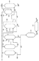
以下、本発明を、図を用いて詳細に説明する。図1は、本発明に用いることできる塩素ガス除害システムの一例である。 Hereinafter, the present invention will be described in detail with reference to the drawings. FIG. 1 is an example of a chlorine gas abatement system that can be used in the present invention.
図1において、塩素ガス除害システムは、第一吸収塔101と、当該第一吸収塔101に接続された第二吸収塔102とを備え、第一吸収塔から排出される生成物を受容するための第一受容器103が第一吸収塔に接続されている。
In FIG. 1, the chlorine gas abatement system includes a
第一吸収塔101および第二吸収塔102の内部には、それぞれ充填物104,105が充填されており、これにより、気液の接触効率を高め、塩素を速やかに除害することができる。
The
当該充填物104,105としては、たとえば、ラシヒリング、ポールリングなどの公知のものを使用することができ、その材料は、たとえば、フッ素樹脂、塩化ビニル樹脂、セラミックス、無機ガラスなどを挙げることができる。
As the
第一吸収塔101には、後述する所定の塩素生成プロセスにより排出された排出ガスが路202を通って投入される。当該排出ガスは、酸素ガスを主成分とし、塩素ガスおよび炭酸ガスを含む。また、第一吸収塔101には、排出ガス中に含まれる塩素ガスの理論量に対し1.0〜1.2倍の量に調整された水酸化ナトリウムが路201を通って投入される。なお、上記排ガス中の炭酸ガス含有量が1%未満の場合は、上記第一吸収塔101へ供給される前に、図示しないpH10以上を維持するアルカリ除害塔で処理することが好ましい。
Exhaust gas discharged by a predetermined chlorine generation process described later is input to the
このようにして、第一吸収塔101において、上記で説明したように、塩素ガスおよび炭酸ガスと水酸化ナトリウムとの反応が生じることになる。当該反応により生成した次亜塩素酸塩および炭酸水素塩は、路203を通って第一受容器103に排出される。第一受容器103中の次亜塩素酸塩および炭酸水素塩は、ポンプP1により吸引され、交換器106により制御されて路203を通って再び第一吸収塔内へ送出されるか、または、路210を通って次の処理に供される。
Thus, in the
また、第一受容器103内のpHは、7〜7.5程度の範囲内に維持されている。これにより、炭酸ナトリウムが析出せず、塩素ガス除害プロセスのサイクルに悪影響を及ぼすことがない。また、第一受容器内の温度は、約30℃以上に維持することが好ましい。次亜塩素酸が熱分解を促進するためである。
Moreover, the pH in the
また、第一吸収塔101において、未反応および/または再生した炭酸ガスならびに未反応の酸素ガスは路204を通って第二吸収塔102へ投入される。この際、上記路204を通って第二吸収塔へ供給されるガス中には、少量の塩素ガスが含有され得る場合もある。
In the
本発明において、このように第一吸収塔内で未反応のガス群を第二吸収塔内へ投入する理由は、当該未反応のガス群の中に少量の塩素ガスが含有される場合もあるので、当該塩素ガスを完全に吸収除去するために、第二吸収塔を設け、当該第二吸収塔内において未反応塩素ガスを完全に吸収かつ除去してしまうためである。 In the present invention, the reason why the unreacted gas group is introduced into the second absorption tower in the first absorption tower in this way is that a small amount of chlorine gas may be contained in the unreacted gas group. Therefore, in order to completely absorb and remove the chlorine gas, a second absorption tower is provided, and the unreacted chlorine gas is completely absorbed and removed in the second absorption tower.
このようにして第二吸収塔内に投入された未反応ガスに対し、塩素ガスの理論量に対して0.001〜0.2倍のアルカリ水溶液を、路206を通して第二吸収塔102へ供給する。これにより、第一吸収塔101内では吸収・除去されなかった塩素ガスをも完全に吸収除去することができるものである。
In this way, 0.001 to 0.2 times as much alkaline aqueous solution as the theoretical amount of chlorine gas is supplied to the
すなわち、本発明は、上述のように第一吸収塔および第二吸収塔において、塩素ガスの理論量に対し、それぞれ1.0〜1.2倍および0.001〜0.2倍の水酸化ナトリウムを二段階的に供給することにより、炭酸ナトリウムなどの析出を生成させずに、塩素ガスを完全に吸収・除去できるものである。 That is, the present invention, as described above, in the first absorption tower and the second absorption tower, the hydroxylation of 1.0 to 1.2 times and 0.001 to 0.2 times the theoretical amount of chlorine gas, respectively. By supplying sodium in two stages, chlorine gas can be completely absorbed and removed without producing precipitation of sodium carbonate or the like.
図1の装置において、第二吸収塔102の頂部に設けられた路208から、未反応の酸素ガスならびに未反応および/または再生した炭酸ガスが放出される。また、第二吸収塔102の底部からは、未反応の水酸化ナトリウム、炭酸水素ナトリウムおよび少量の次亜塩素酸塩が路209を通って排出され、これらの水酸化ナトリウム、炭酸水素ナトリウムおよび次亜塩素酸塩は、ポンプP2により吸引され、交換器107により、路205または路207のいずれかに送出される。
In the apparatus of FIG. 1, unreacted oxygen gas and unreacted and / or regenerated carbon dioxide gas are released from a
路207を通って送出された場合は、路203を通って再び第一吸収塔内101へ投入される。路203を通って第一吸収塔内101へ供給された次亜塩素酸塩は、第一吸収塔101の底部から路203を通って第一受容器103へ排出される。
When it is sent through the
また、路205を通って第二吸収塔102へ供給された水酸化ナトリウム、炭酸水素ナトリウムおよび次亜塩素酸塩においては、水酸化ナトリウムおよび炭酸水素ナトリウムは第二吸収塔102内で再び塩素ガスとの反応に寄与し、次亜塩素酸塩はそのまま底部から排出され、上記のサイクルを繰り返す。
In addition, in the sodium hydroxide, sodium hydrogen carbonate and hypochlorite supplied to the
本発明において、図1中の路210通って送出された後のプロセスに用いる装置を図2に示す。図2において、路210は、熱分解槽112に接続され、路210から送出された次亜塩素酸塩および炭酸水素塩は、熱分解槽112へ投入される。
In the present invention, an apparatus used for the process after being sent through the
また、熱分解槽112には、後述する塩素生成プロセスにおける図示しない排ガス除害塔から排出される次亜塩素酸塩も投入されるものである。第三受容器113は当該次亜塩素酸塩水溶液を保有し、当該第三受容器113からポンプP5により吸引して路212を介して熱分解層112に次亜塩素酸塩水溶液が投入される。ここで、第三受容器113に保有される次亜塩素酸塩水溶液は、通常pHが約13〜14の範囲内であり、濃度は約10%である。
The
熱分解槽112において、路210および路212によって投入された次亜塩素酸塩水溶液をpH7.0〜8.0の範囲内に維持して30℃以上に加熱する。当該温度に加熱することで、次亜塩素酸塩が熱分解して塩化物と酸素(O2)とを生成する。生成した酸素はパージ弁(図示せず)などにより系外に導かれる。
In the
ここで、当該温度が30℃未満であると、次亜塩素酸塩の熱分解に長時間を要して実用的ではなく、また未分解の次亜塩素酸塩が多く残るために、後に加える硫黄系還元剤の使用量が多くなる傾向にあって、好ましくない。加熱温度は高いほど短時間で次亜塩素酸塩を熱分解できて好ましいが、熱分解槽112に用いる材料の耐久性の観点から、通常は60℃程度以下である。また、熱分解層112におけるpHは、次亜塩素酸ナトリウムの分解の促進のために、7〜8の範囲内に調整することが好ましい。pH調整のために、路213bにより塩酸等の無機酸を供給してもよい。
Here, if the temperature is lower than 30 ° C., it takes a long time to thermally decompose hypochlorite, which is not practical, and a large amount of undecomposed hypochlorite remains. This is not preferable because the amount of the sulfur-based reducing agent tends to increase. A higher heating temperature is preferable because hypochlorite can be thermally decomposed in a shorter time, but from the viewpoint of durability of the material used for the
熱分解槽112は、次亜塩素酸塩水溶液と接触する面がガラス繊維強化プラスチックのような安価な樹脂材料で構成されていてもよいが、60℃以上に加熱する場合にはチタン系材料やフッ素樹脂材料で構成されていることが好ましく、内面が全面にわたってチタン系材料やフッ素樹脂材料で構成されていてもよい。これにより、熱分解槽112は次亜塩素酸塩などによる侵食を受けることなく、次亜塩素酸塩水溶液を60℃以上に加熱することができる。チタン系材料としては、例えば金属チタンのほか、チタン合金などが挙げられる。
The
熱分解槽112では、熱分解後の熱分解液中の有効塩素濃度が0となるまで加熱して熱分解させてもよいが、多大な時間およびエネルギーを必要とするので、通常は未分解の次亜塩素酸塩が熱分解液に残留する程度、具体的には加熱前の次亜塩素酸塩水溶液の有効塩素濃度の1/5以下、好ましくは1/10以下となるまで次亜塩素酸塩を熱分解すればよい。
In the
熱分解槽112における加熱時間は通常1時間以上50時間以下であることが好ましく、より好ましくは1時間以上20時間以下の範囲である。また、次亜塩素酸塩水溶液は通常、回分式で加熱され熱分解されるが、連続式で加熱され熱分解されてもよい。なお、熱分解液に残留する未分解の次亜塩素酸塩は、還元分解槽114で硫黄系還元剤を用いて還元分解されることになる。
The heating time in the
上述のようにして次亜塩素酸塩水溶液を加熱することで、次亜塩素酸塩が熱分解された熱分解液が得られる。当該熱分解液はポンプP3により吸引され路211を通って図示しない冷却器を介し、路215を経由して還元分解槽114に導かれる。ここで、熱分解後の熱分解液が十分に冷却されていない場合は、また未分解の次亜塩素酸塩が残留しているので、ポンプP3、路211および路215などは、熱分解液と接触する面がチタン系材料、フッ素樹脂などで構成されていることが、耐久性の点から好ましい。
By heating the hypochlorite aqueous solution as described above, a thermal decomposition liquid in which hypochlorite is thermally decomposed is obtained. The thermal decomposition liquid is sucked by the pump P3, passes through the
還元分解槽114には、硫黄系還元剤が路214を通って投入され、冷却された熱分解液と硫黄系還元剤とが混合される。熱分解液が硫黄系還元剤と混合されることで、熱分解液に含まれる未分解の次亜塩素酸塩が還元され、分解される。熱分解液は通常、回分式で還元され分解されるが、連続式で還元され分解されてもよい。当該硫黄系還元剤としては、亜硫酸ナトリウムを用いることができる。
A sulfur-based reducing agent is introduced into the
このようにして、次亜塩素酸塩水溶液に含まれる次亜塩素酸塩が分解されるが、次亜塩素酸塩水溶液は通常、アルカリ性であるので、熱分解液も通常はアルカリ性であり、このため、中和しておくことが好ましい。中和するには、例えば還元分解槽114に、熱分解液に路213を通って送出される酸を路215を介して加えることによって熱分解液を中和することができる。
In this way, hypochlorite contained in the hypochlorite aqueous solution is decomposed. However, since the hypochlorite aqueous solution is usually alkaline, the pyrolysis solution is also usually alkaline. Therefore, it is preferable to neutralize. In order to neutralize, for example, the thermal decomposition solution can be neutralized by adding an acid sent through the
当該酸としては、例えば塩酸、硫酸、硝酸などの無機酸が好ましく用いられるが、後述する塩素生成プロセスによって塩酸を得ることができ、塩酸を再利用できるという観点から、塩酸が好ましい。当該酸の使用量は熱分解液のpHに応じて適宜調整することが好ましい。 As the acid, for example, an inorganic acid such as hydrochloric acid, sulfuric acid, and nitric acid is preferably used, and hydrochloric acid is preferable from the viewpoint that hydrochloric acid can be obtained by a chlorine generation process described later and hydrochloric acid can be reused. The amount of the acid used is preferably adjusted as appropriate according to the pH of the thermal decomposition solution.
このようにして、第一吸収塔101から排出された次亜塩素酸塩は分解される。すなわち、熱分解層112において次亜塩素酸塩水溶液を30℃以上に加熱して該水溶液に含まれる次亜塩素酸塩を熱分解し、必要に応じて熱分解された後の熱分解液を冷却したのち硫黄系還元剤と混合して、前記熱分解液に含まれる未分解の次亜塩素酸塩を還元分解層114において還元分解することにより、次亜塩素酸塩水溶液に含まれる次亜塩素酸塩を分解することができ、還元分解した後の還元分解液には、次亜塩素酸塩が含まれていない。
In this way, the hypochlorite discharged from the
次いで、還元分解液をポンプP4で吸引し、路217および路216を介して第二受容器115へ投入する。また、第二受容器115には、路218を介して後述する塩素生成プロセスにおいて生じた酸が投入され、これにより、還元分解液を中和することができる。
Next, the reductive decomposition liquid is sucked by the pump P4 and is introduced into the
次いで、第二受容器115における反応後の液を、ポンプP6により吸引し、路219を介して排水されることとなる。
Next, the liquid after the reaction in the
次に、第一吸収塔内および第二吸収塔内へ供給する水酸化ナトリウム水溶液の制御方法について、図3を用いて説明する。なお、図3において説明しない番号の構成は、図1のものと同一である。 Next, the control method of the sodium hydroxide aqueous solution supplied into the first absorption tower and the second absorption tower will be described with reference to FIG. In addition, the structure of the number which is not demonstrated in FIG. 3 is the same as the thing of FIG.
図3において、路202には塩素ガスモニタおよび流量計108が接続され、路202を通過する排ガス中の塩素ガスの濃度および流量を連続的に測定する。また、塩素ガスモニタおよび流量計108には、制御装置109が接続され、塩素ガスモニタおよび流量計108からの信号を受信する。ここで、連続的に測定するとは、間断なく、または、10分以下の間隔で断続的に測定することを意味する。
In FIG. 3, a chlorine gas monitor and a
さらに、制御装置109には、第一アルカリ水溶液供給装置110および第二アルカリ水溶液供給装置111が接続され、当該第一アルカリ水溶液供給装置110は、水酸化ナトリウムを保有し、これを路201を介して第一吸収塔101内に供給し、また、当該第二アルカリ水溶液供給装置111は、水酸化ナトリウムを保有し、これを路206を介して第二吸収塔102内に供給する。
Further, a first alkaline aqueous
次に、これらの装置を用いた制御について説明する。まず、塩素ガスモニタおよび流量計108によって測定された路202を通過する排ガス中の塩素ガスの濃度に関する信号が、制御装置109に送信される。当該信号を受信した制御装置109は、当該装置に内に組み込まれたプログラムによって、塩素ガスを吸収するのに必要なアルカリ金属塩および/またはアルカリ土類金属塩の理論量が計算され、当該計算値に対して1.0〜1.2倍の量および0.001〜0.2倍の量が算出される。
Next, control using these devices will be described. First, a signal related to the concentration of chlorine gas in the exhaust gas passing through the
次いで、制御装置109は、当該算出結果に応じて、第一アルカリ水溶液供給装置110および第二アルカリ水溶液供給装置111を制御して、上記算出結果に基づき第一吸収塔101および第二吸収塔102に供給されるアルカリ水溶液の量を調節する。
Next, the
当該制御装置109の制御には、第一アルカリ水溶液供給装置110から第一吸収塔101内へ供給されるアルカリ水溶液の濃度および流量が含まれる。また、同様に、当該制御には、第二アルカリ水溶液供給装置111から第二吸収塔102内へ供給されるアルカリ水溶液の濃度および流量が含まれる。
The control of the
このようにして、水酸化ナトリウム溶液の供給を制御することにより、人による管理を低減できる。また、排ガス中の塩素ガス濃度は一定でないため、供給するアルカリ水溶液の微調整が困難であるが、制御装置を用いて制御することにより、微調整が可能となり、より確実に塩素の吸収除去が可能となり、炭酸塩等の析出も防止できる。 In this way, control by the person can be reduced by controlling the supply of the sodium hydroxide solution. In addition, since the chlorine gas concentration in the exhaust gas is not constant, it is difficult to finely adjust the alkaline aqueous solution to be supplied. However, fine adjustment is possible by controlling using the control device, and chlorine absorption and removal can be performed more reliably. This makes it possible to prevent precipitation of carbonates and the like.
また、図3において、第一吸収塔101に接続された路204および第二吸収塔102に接続された路208には、それぞれ図示しない第一塩素ガスモニタおよび第二塩素ガスモニタが接続されていることが好ましい。当該ガスモニタは、それぞれ第一吸収塔101および第二吸収塔102の頂部に設置することもできる。
In FIG. 3, a first chlorine gas monitor and a second chlorine gas monitor (not shown) are connected to the
これにより、第一吸収塔101から第二吸収塔102へ供給されるガスのうちの塩素ガス濃度を測定することができ、当該測定により、第二吸収塔102への過剰な塩素ガスの供給がある場合などに、システム中の異常事態への対処を容易とすることができる。また、当該モニタと制御装置109とを接続させて、第二吸収塔102へ供給するアルカリ水溶液の供給量を制御させることもできる。
Thereby, the chlorine gas concentration of the gas supplied from the
同様に、第二塩素ガスモニタを設置することにより、第一吸収塔102から外部へ放出されるガスのうちの塩素ガス濃度を測定することができ、当該測定により、外部への過剰な塩素ガスの供給がある場合などに、システムの稼動を中止させることにより、外部への塩素の過剰な供給を防止することができる。また、当該モニタと制御装置109とを接続させて、第二吸収塔102へ供給するアルカリ水溶液の供給量を制御させ、外部へ放出される塩素ガスを消滅させることもできる。
Similarly, by installing the second chlorine gas monitor, it is possible to measure the chlorine gas concentration of the gas released from the
次に、図1〜3において、路202から供給される塩素ガス含有排ガスの発生プロセスについて説明する。すなわち、塩化水素を含むガスを、酸素を含むガスを用いて酸化する塩素の製造方法であって、下記の工程を有する塩素の製造方法によって排出される。
Next, the generation process of the chlorine gas-containing exhaust gas supplied from the
反応工程:ルテニウムおよび/またはルテニウム化合物を含む触媒の存在下、塩化水素を含むガスを酸素で酸化し、塩素、水、未反応塩化水素および未反応酸素を主成分とするガスを得る工程。吸収工程:反応工程で得た塩素、水、未反応塩化水素および未反応酸素を主成分とするガスを、水および/または塩酸水と接触させることにより、および/または、冷却することにより、塩化水素と水を主成分とする溶液を回収し、塩素と未反応酸素を主成分とするガスを得る工程。乾燥工程:吸収工程で得たガス中の水分を除去することにより、乾燥したガスを得る工程。精製工程:乾燥工程で得た乾燥したガスを、塩素を主成分とする液体またはガスと未反応酸素を主成分とするガスとに分離することにより塩素を得る工程。当該工程において、未反応酸素を主成分とするガスの一部を、本発明が処理対象とするものである。 Reaction step: A step of oxidizing a gas containing hydrogen chloride with oxygen in the presence of a catalyst containing ruthenium and / or a ruthenium compound to obtain a gas mainly composed of chlorine, water, unreacted hydrogen chloride and unreacted oxygen. Absorption process: A gas mainly composed of chlorine, water, unreacted hydrogen chloride and unreacted oxygen obtained in the reaction process is brought into contact with water and / or hydrochloric acid and / or cooled to be chlorinated. A step of collecting a solution containing hydrogen and water as main components to obtain a gas containing chlorine and unreacted oxygen as main components. Drying step: A step of obtaining a dried gas by removing moisture in the gas obtained in the absorption step. Purification step: A step of obtaining chlorine by separating the dried gas obtained in the drying step into a liquid or gas containing chlorine as a main component and a gas containing unreacted oxygen as a main component. In this process, the present invention treats a part of the gas containing unreacted oxygen as a main component.
上記各工程について、図4を用いて具体的に説明する。図4は、酸素ガスと塩化水素ガスとから塩素ガスを製造するプロセスに用いるシステムの一例を示す模式図である。 Each of the above steps will be specifically described with reference to FIG. FIG. 4 is a schematic diagram showing an example of a system used in a process for producing chlorine gas from oxygen gas and hydrogen chloride gas.
図4において、原料の塩化水素ガスは、路222を通って前処理塔116に投入される。原料の塩化水素ガスとしては、塩素化合物の熱分解反応等において発生する塩化水素のように、当該分野で公知のプロセスにより発生した塩化水素含有ガスを用いることができる。この際、不純物として、一酸化炭素、ホスゲン、硫化水素、二酸化硫黄、四塩化炭素、クロロベンゼンおよびジクロロベンゼン等が含まれるが、上記前処理塔116において、当該不純物を除去するものである。なお、原料の塩化水素ガス中には、塩化水素ガスが50体積%程度以上含まれていることが好ましい。
In FIG. 4, the raw material hydrogen chloride gas is introduced into the
前処理塔116において不純物が除去された原料塩化水素ガスは、路221を通って投入された酸素ガスと共に路223を通って反応塔117へ投入される。当該酸素ガスは、酸素または空気を用いることができるが、好ましくは酸素濃度が80体積%以上のものが好ましい。
The raw material hydrogen chloride gas from which impurities have been removed in the
当該反応塔117において、上記反応工程に示した反応が行われる。すなわち、ルテニウムおよび/またはルテニウム化合物を含む触媒の存在下、前処理塔116で処理された塩化水素を含むガスを、酸素を含むガスで酸化し、塩素、水、未反応塩化水素および未反応酸素を主成分とするガスを得る。
In the reaction tower 117, the reaction shown in the reaction step is performed. That is, in the presence of a catalyst containing ruthenium and / or a ruthenium compound, a gas containing hydrogen chloride treated in the
塩化水素を酸素で酸化するに際しては、ルテニウムおよび/またはルテニウム化合物を含む触媒を用い、固定床反応器にて反応させる。このことにより、触媒成分の揮発や飛散による配管等の閉塞トラブルを伴わず、かつ揮発や飛散した触媒成分の処理工程を必要とせず、また平衡的に有利な温度で塩素を製造できるために、未反応塩化水素と水を回収する工程、塩素と未反応酸素を分離する工程および未反応酸素を反応に供給する工程を簡略化し、よって設備コストおよび運転コストを低く抑制し得る。 In oxidizing hydrogen chloride with oxygen, a catalyst containing ruthenium and / or a ruthenium compound is used and reacted in a fixed bed reactor. Because of this, it is possible to produce chlorine at a temperature that is advantageous in an equilibrium manner, without causing troubles such as clogging of piping due to volatilization or scattering of the catalyst component, and without requiring a treatment process of the volatilized or scattered catalyst component. The step of recovering unreacted hydrogen chloride and water, the step of separating chlorine and unreacted oxygen, and the step of supplying unreacted oxygen to the reaction can be simplified, so that the equipment cost and operating cost can be kept low.
ルテニウムおよび/またはルテニウム化合物を含む触媒としては、公知の触媒(特開平9−67103号公報、特開平10−182104号公報、特開平10−194705号公報、特開平10−338502号公報、特開平11−180701号公報)を用いることができる。中でも酸化ルテニウムを含む触媒が好ましい。更に、触媒中の酸化ルテニウムの含有量は、0.1〜20質量%が好ましい。酸化ルテニウムの量が過小であると触媒活性が低く塩化水素の転化率が低くなる場合があり、一方、酸化ルテニウムの量が過多であると触媒価格が高くなる場合がある。たとえば、特開平10−338502号公報には、酸化ルテニウムの含有量が0.1〜20質量%であり、酸化ルテニウムの中心径が1.0〜10.0ナノメートルである担持酸化ルテニウム触媒または酸化ルテニウム複合酸化物型触媒が記載されている。 As catalysts containing ruthenium and / or ruthenium compounds, known catalysts (Japanese Patent Laid-Open Nos. 9-67103, 10-182104, 10-194705, 10-338502, 10-338502, 11-180701). Of these, a catalyst containing ruthenium oxide is preferable. Furthermore, the content of ruthenium oxide in the catalyst is preferably 0.1 to 20% by mass. If the amount of ruthenium oxide is too small, the catalytic activity may be low and the conversion rate of hydrogen chloride may be low. On the other hand, if the amount of ruthenium oxide is excessive, the catalyst price may be high. For example, JP-A-10-338502 discloses a supported ruthenium oxide catalyst having a ruthenium oxide content of 0.1 to 20% by mass and a ruthenium oxide central diameter of 1.0 to 10.0 nanometers. A ruthenium oxide composite oxide type catalyst is described.
上記反応塔117において行われた触媒反応により生成した、塩素、水、未反応塩化水素および未反応酸素を主成分とするガスは、路224を通って吸収塔118へ投入される。ここで、上述した吸収工程が行われる。
A gas mainly composed of chlorine, water, unreacted hydrogen chloride, and unreacted oxygen generated by the catalytic reaction performed in the reaction tower 117 is input to the
すなわち、反応工程で得た塩素、水、未反応塩化水素および未反応酸素を主成分とするガスを、路236より供給される水および/または塩酸と接触させることにより、および/または、冷却することにより、塩化水素と水を主成分とする溶液を回収し、塩素と未反応酸素を主成分とするガスを得る。得られたガスは、路225を通って乾燥塔119へ供給されることになる。また、塩化水素と水とを主成分とする溶液は、路237を通って塩酸吸収塔122に投入される。
That is, the gas mainly composed of chlorine, water, unreacted hydrogen chloride and unreacted oxygen obtained in the reaction step is brought into contact with water and / or hydrochloric acid supplied from the
上記吸収工程において、接触温度は0〜100℃、圧力は0.05〜1MPaで行われることが好ましい。接触させる塩酸水の濃度は、25質量%以下が好ましい。また、塩素水和物析出防止のために、特開2003−261306号公報に記載の方法を採用することが好ましい。 In the absorption step, the contact temperature is preferably 0 to 100 ° C. and the pressure is 0.05 to 1 MPa. The concentration of hydrochloric acid to be contacted is preferably 25% by mass or less. In order to prevent precipitation of chlorine hydrate, it is preferable to employ the method described in JP-A-2003-261306.
次に、乾燥塔119において上述した乾燥工程が行われる。すなわち、吸収工程で得たガス中の水分を除去する。乾燥工程後のガス中の水分は0.5mg/l以下、好ましくは0.1mg/l以下である。ガス中の水分を除去する化合物としては、硫酸、塩化カルシウム、過塩素酸マグネシウム、ゼオライトなどがあげられるが、中でも硫酸が好ましい。
Next, the drying process described above is performed in the drying
硫酸の濃度は、90質量%以上が好ましい。硫酸濃度が90質量%よりも小さいと、ガス中の水分が十分に除去されないことがある。接触温度は0〜80℃、圧力は0.05〜1MPaで行われることが好ましい。また、当該乾燥工程に用いた硫酸の廃液は、路239を通って廃棄されることになる。なお、乾燥剤として硫酸を用いた場合には、乾燥工程の直後で硫酸ミストを除去することが好ましい。たとえば、ブリンクエリミネータや特開2003−181235号公報に記載の方法を用いることができる。
The concentration of sulfuric acid is preferably 90% by mass or more. If the sulfuric acid concentration is lower than 90% by mass, moisture in the gas may not be sufficiently removed. The contact temperature is preferably 0 to 80 ° C. and the pressure is 0.05 to 1 MPa. In addition, the waste liquid of sulfuric acid used in the drying process is discarded through the
乾燥工程によって水分を除去されたガスは、次いで、路226を通り塩素精製塔121へ供給される。ここで、塩素精製塔121に供給される前に、必要に応じてコンプレッサを介することもある。当該コンプレッサにより、水分除去後のガスを圧縮して塩素の液化を容易とする。
The gas from which moisture has been removed by the drying process is then supplied to the
次いで、塩素精製塔121において、上述した精製工程が行われる。すなわち、乾燥工程で得たガスを、塩素を主成分とする液体またはガスと未反応酸素を主成分とするガスとに分離することにより塩素を得る。塩素を主成分とする液体またはガスと未反応酸素を主成分とするガスとに分離する方法としては、圧縮および/または冷却する方法、および/または公知の方法(特開平3−262514号公報、特表平11−500954号公報)があげられる。
Next, the above-described purification process is performed in the
たとえば、乾燥工程で得たガスを圧縮および/または冷却することによって、塩素を主成分とする液体が未反応酸素を主成分とするガスと分離される。塩素の液化は、圧力と温度で規定される塩素が液体状態で存在しうる範囲で実施される。その範囲で低温にすればするほど、圧縮圧力が低くなるために圧縮動力は小さくできるが、工業的には設備等の問題から、圧縮圧力と冷却温度はこの範囲内の最適な経済条件を考慮して決められる。通常の運転においては、塩素液化の圧縮圧力は0.5〜5MPa、冷却温度は−70〜40℃で行われる。 For example, by compressing and / or cooling the gas obtained in the drying step, a liquid containing chlorine as a main component is separated from a gas containing unreacted oxygen as a main component. The liquefaction of chlorine is carried out to the extent that chlorine specified by pressure and temperature can exist in a liquid state. The lower the temperature, the lower the compression pressure, so the compression power can be reduced. However, from the industrial viewpoint, the compression pressure and cooling temperature take into account the optimal economic conditions within this range. Can be decided. In normal operation, the compression pressure for liquefaction of chlorine is 0.5 to 5 MPa, and the cooling temperature is −70 to 40 ° C.
得られた塩素を主成分とする液体は、路228を通って採取され、そのまま、あるいは一部または全部を気化させた後、塩化ビニル、ホスゲンなどの原料として用いることができる。一部または全部を気化させた後に用いる場合は、乾燥工程で得られるガスとの熱交換を行うことにより、気化に必要な熱の一部を得ると同時に、乾燥工程で得られるガス中の塩素の液化に必要な外部冷媒による冷却負荷を削減することが可能である。同様に、塩素蒸留塔117の還流液の冷却に用いることもできる。
The obtained liquid containing chlorine as a main component is collected through the
上記精製工程において、未反応の酸素を主成分とするガスの大部分は、路230を通って反応工程に循環されるか、または、路229を通って排ガスとして処理されることになる。ここで、当該未反応の酸素を主成分とするガス中には、塩素ガスが含まれている場合もある。本発明は、このような排ガス中の塩素ガスを除害の対象の1つとするものである。
In the purification step, most of the gas mainly composed of unreacted oxygen is circulated to the reaction step through the
上述したように、未反応の酸素を主成分とするガスの一部または全部は、路230を通って上述の循環工程に供される。すなわち、当該未反応酸素を主成分とするガスの一部または全部を反応工程に用いる酸素として供給する。反応工程へ供給するガス中に硫酸ミストが含有される場合は、硫酸ミストを除去することが好ましい。すなわち、路240を通って水が供給されている洗浄塔120において、硫酸ミストを除去して、上記ガスを洗浄し、洗浄された酸素ガスを、路232を通して反応塔117へ供給するものである。その他の硫酸ミストを除去する方法としては、公知の方法(特開2002−136825号公報)があげられる。また、水に溶解した当該硫酸ミストは、洗浄塔120から路231を通って吸収塔118へ供給され、塩酸と同様に、吸収工程に用いられ得る。
As described above, part or all of the gas mainly composed of unreacted oxygen is supplied to the above-described circulation process through the
上記精製工程において、路229を通って排出される、未反応の酸素を主成分とする排ガスは、さらに路202を通って第一吸収塔101に投入され、本発明の塩素ガスの除害方法に供されることになる。
In the purification step, the exhaust gas mainly composed of unreacted oxygen discharged through the
吸収工程において、路237より排出された塩化水素と水とを主成分とする溶液は、当該溶液中に含まれる塩素は、加熱、および/または窒素等の不活性なガスのバブリングにより除去した後に、塩酸吸収塔122へ投入される。塩酸吸収塔122において、塩酸濃度が調整される。当該処理を受けた塩素は排ガス除害塔(図示せず)へ送出される。また、当該処理後の溶液は、さらに路234を通って活性炭塔123へ投入され、溶液中の有機不純物等が除去された後、路235を通って送出され、送出された塩酸は、電解槽のpH調整、ボイラ−フィ−ド水の中和、アニリンとホルマリンの縮合転位反応および塩酸水電解の原料や、食品添加物等に用いることができる。また、路237より排出した溶液は、特開2001−139305号公報に記載の方法で塩化水素を回収して反応原料として用いることも可能である。
In the absorption process, after the solution containing hydrogen chloride and water discharged from the
今回開示された実施の形態および実施例はすべての点で例示であって制限的なものではないと考えられるべきである。本発明の範囲は上記した説明ではなくて特許請求の範囲によって示され、特許請求の範囲と均等の意味および範囲内でのすべての変更が含まれることが意図される。 It should be understood that the embodiments and examples disclosed herein are illustrative and non-restrictive in every respect. The scope of the present invention is defined by the terms of the claims, rather than the description above, and is intended to include any modifications within the scope and meaning equivalent to the terms of the claims.
101 第一吸収塔、102 第二吸収塔、103 第一受容器、104,105,106,107 交換器、108 塩素ガスモニタおよび流量計、109 制御装置、110 第一アルカリ水溶液供給装置、111 第二アルカリ水溶液供給装置、112 熱分解槽、113 第三受容器、114 還元分解槽、115 第二受容器、116 前処理塔、117 反応塔、118 吸収塔、119 乾燥塔、120 洗浄塔、121 塩素精製塔、122 塩酸吸収塔、123 活性炭塔、201,202,203,204,205,206,207,208,209,210,211,212,213,213b,214,215,216,217,218,219,220,221,222,223,224,225,226,227,228,229,230,231,232,233,234,235,236,237,238,239,240 路、P1,P2,P3,P4 ポンプ。
DESCRIPTION OF
Claims (13)
1.反応ステップ:ルテニウムおよび/またはルテニウム化合物を含む触媒の存在下、塩化水素を含むガスを酸素で酸化し、塩素、水、未反応塩化水素および未反応酸素を主成分とするガスを得るステップ、
2.吸収ステップ:反応ステップで得た塩素、水、未反応塩化水素および未反応酸素を主成分とするガスを、水および/または塩酸水と接触させることにより、および/または、冷却することにより、塩化水素と水を主成分とする溶液を回収し、塩素と未反応酸素を主成分とするガスを得るステップ、
3.乾燥ステップ:吸収ステップで得たガス中の水分を除去することにより、乾燥したガスを得るステップ、
4.精製ステップ:乾燥ステップで得た乾燥したガスを、塩素を主成分とする液体またはガスと、未反応酸素を主成分とする炭酸ガスおよび塩素ガスを含む排ガスとに分離することにより塩素を得るステップ。 The said exhaust gas is discharged | emitted in the manufacturing method of chlorine including the following steps 1-4, The chlorine gas elimination method in any one of Claims 1-11 characterized by the above-mentioned.
1. Reaction step: oxidizing a gas containing hydrogen chloride with oxygen in the presence of a catalyst containing ruthenium and / or a ruthenium compound to obtain a gas mainly composed of chlorine, water, unreacted hydrogen chloride and unreacted oxygen;
2. Absorption step: A gas mainly composed of chlorine, water, unreacted hydrogen chloride and unreacted oxygen obtained in the reaction step is brought into contact with water and / or hydrochloric acid and / or cooled to be chlorinated. Recovering a solution mainly composed of hydrogen and water to obtain a gas mainly composed of chlorine and unreacted oxygen;
3. Drying step: a step of obtaining a dried gas by removing moisture in the gas obtained in the absorption step;
4). Purification step: A step of obtaining chlorine by separating the dried gas obtained in the drying step into a liquid or gas mainly composed of chlorine and an exhaust gas containing carbon dioxide gas and chlorine gas mainly composed of unreacted oxygen. .
Priority Applications (1)
| Application Number | Priority Date | Filing Date | Title |
|---|---|---|---|
| JP2004301864A JP4553674B2 (en) | 2004-10-15 | 2004-10-15 | How to remove chlorine gas |
Applications Claiming Priority (1)
| Application Number | Priority Date | Filing Date | Title |
|---|---|---|---|
| JP2004301864A JP4553674B2 (en) | 2004-10-15 | 2004-10-15 | How to remove chlorine gas |
Publications (2)
| Publication Number | Publication Date |
|---|---|
| JP2005305414A true JP2005305414A (en) | 2005-11-04 |
| JP4553674B2 JP4553674B2 (en) | 2010-09-29 |
Family
ID=35434783
Family Applications (1)
| Application Number | Title | Priority Date | Filing Date |
|---|---|---|---|
| JP2004301864A Expired - Fee Related JP4553674B2 (en) | 2004-10-15 | 2004-10-15 | How to remove chlorine gas |
Country Status (1)
| Country | Link |
|---|---|
| JP (1) | JP4553674B2 (en) |
Cited By (14)
| Publication number | Priority date | Publication date | Assignee | Title |
|---|---|---|---|---|
| WO2008041781A1 (en) * | 2006-10-03 | 2008-04-10 | Sumitomo Chemical Company, Limited | Method for removal of chlorine gas |
| JP2008110339A (en) * | 2006-10-03 | 2008-05-15 | Sumitomo Chemical Co Ltd | Method for removal of chlorine gas |
| JP2012520228A (en) * | 2009-03-11 | 2012-09-06 | ビーエーエスエフ ソシエタス・ヨーロピア | Method for producing phosgene |
| CN102974208A (en) * | 2012-11-27 | 2013-03-20 | 常州大学 | Chlorine-containing tail-gas purification and treatment device with regenerated residual chlorine processing function |
| WO2013137297A1 (en) | 2012-03-13 | 2013-09-19 | 出光興産株式会社 | Method for continuous production of polycarbonate |
| CN103877847A (en) * | 2014-04-02 | 2014-06-25 | 李景致 | Liquid caustic soda quality method for protecting leaked chlorine absorption device |
| CN104096468A (en) * | 2014-06-07 | 2014-10-15 | 李安民 | Tail gas absorption process and equipment for bis(trichloromethyl)carbonate production |
| WO2016110081A1 (en) * | 2015-01-09 | 2016-07-14 | 南京格洛特环境工程股份有限公司 | Acid waste gas treatment and resource utilization |
| CN107010599A (en) * | 2017-03-30 | 2017-08-04 | 安徽八化工股份有限公司 | A kind of sodium hypochlorite continuous production device |
| CN107885081A (en) * | 2017-11-13 | 2018-04-06 | 浙江大学 | A kind of internal thermally coupled air separation column online observation device for product design curve |
| CN109485017A (en) * | 2018-11-29 | 2019-03-19 | 营创三征(营口)精细化工有限公司 | It is a kind of to synthesize sodium hypochlorite technique using Cyanuric Chloride tail gas |
| CN111589292A (en) * | 2020-05-28 | 2020-08-28 | 山东振曦新材料科技有限公司 | Non-alkalization treatment process for tail gas of methyl chloride fatty acid |
| CN111624879A (en) * | 2020-05-20 | 2020-09-04 | 北京国电龙源环保工程有限公司 | Online adaptive control system and method for concentration tower |
| KR20230125025A (en) | 2020-12-25 | 2023-08-28 | 가부시끼가이샤 레조낙 | Catalyst for decomposing chlorine gas, exhaust gas treatment device and method for decomposing chlorine gas |
Citations (5)
| Publication number | Priority date | Publication date | Assignee | Title |
|---|---|---|---|---|
| JPS50125974A (en) * | 1974-03-20 | 1975-10-03 | ||
| JPS5482375A (en) * | 1977-12-14 | 1979-06-30 | Kubota Ltd | Refining apparatus for gas |
| JPH03131319A (en) * | 1989-07-01 | 1991-06-04 | Hoechst Ag | Method of absorbing chlorine selectively from carbon dioxide containing waste gas |
| JPH0952022A (en) * | 1995-08-17 | 1997-02-25 | Ishihara Sangyo Kaisha Ltd | Chlorine gas treatment method |
| JP2000272906A (en) * | 1999-01-22 | 2000-10-03 | Sumitomo Chem Co Ltd | Production of chlorine |
-
2004
- 2004-10-15 JP JP2004301864A patent/JP4553674B2/en not_active Expired - Fee Related
Patent Citations (5)
| Publication number | Priority date | Publication date | Assignee | Title |
|---|---|---|---|---|
| JPS50125974A (en) * | 1974-03-20 | 1975-10-03 | ||
| JPS5482375A (en) * | 1977-12-14 | 1979-06-30 | Kubota Ltd | Refining apparatus for gas |
| JPH03131319A (en) * | 1989-07-01 | 1991-06-04 | Hoechst Ag | Method of absorbing chlorine selectively from carbon dioxide containing waste gas |
| JPH0952022A (en) * | 1995-08-17 | 1997-02-25 | Ishihara Sangyo Kaisha Ltd | Chlorine gas treatment method |
| JP2000272906A (en) * | 1999-01-22 | 2000-10-03 | Sumitomo Chem Co Ltd | Production of chlorine |
Cited By (17)
| Publication number | Priority date | Publication date | Assignee | Title |
|---|---|---|---|---|
| JP2008110339A (en) * | 2006-10-03 | 2008-05-15 | Sumitomo Chemical Co Ltd | Method for removal of chlorine gas |
| WO2008041781A1 (en) * | 2006-10-03 | 2008-04-10 | Sumitomo Chemical Company, Limited | Method for removal of chlorine gas |
| KR101778312B1 (en) * | 2009-03-11 | 2017-09-13 | 바스프 에스이 | Method for producing phosgene |
| JP2012520228A (en) * | 2009-03-11 | 2012-09-06 | ビーエーエスエフ ソシエタス・ヨーロピア | Method for producing phosgene |
| WO2013137297A1 (en) | 2012-03-13 | 2013-09-19 | 出光興産株式会社 | Method for continuous production of polycarbonate |
| CN102974208A (en) * | 2012-11-27 | 2013-03-20 | 常州大学 | Chlorine-containing tail-gas purification and treatment device with regenerated residual chlorine processing function |
| CN103877847A (en) * | 2014-04-02 | 2014-06-25 | 李景致 | Liquid caustic soda quality method for protecting leaked chlorine absorption device |
| CN104096468A (en) * | 2014-06-07 | 2014-10-15 | 李安民 | Tail gas absorption process and equipment for bis(trichloromethyl)carbonate production |
| WO2016110081A1 (en) * | 2015-01-09 | 2016-07-14 | 南京格洛特环境工程股份有限公司 | Acid waste gas treatment and resource utilization |
| CN107010599A (en) * | 2017-03-30 | 2017-08-04 | 安徽八化工股份有限公司 | A kind of sodium hypochlorite continuous production device |
| CN107010599B (en) * | 2017-03-30 | 2023-07-07 | 安徽八一化工股份有限公司 | Sodium hypochlorite continuous production device |
| CN107885081A (en) * | 2017-11-13 | 2018-04-06 | 浙江大学 | A kind of internal thermally coupled air separation column online observation device for product design curve |
| CN109485017A (en) * | 2018-11-29 | 2019-03-19 | 营创三征(营口)精细化工有限公司 | It is a kind of to synthesize sodium hypochlorite technique using Cyanuric Chloride tail gas |
| CN111624879A (en) * | 2020-05-20 | 2020-09-04 | 北京国电龙源环保工程有限公司 | Online adaptive control system and method for concentration tower |
| CN111624879B (en) * | 2020-05-20 | 2022-07-29 | 国能龙源环保有限公司 | Online adaptive control system and method for concentration tower |
| CN111589292A (en) * | 2020-05-28 | 2020-08-28 | 山东振曦新材料科技有限公司 | Non-alkalization treatment process for tail gas of methyl chloride fatty acid |
| KR20230125025A (en) | 2020-12-25 | 2023-08-28 | 가부시끼가이샤 레조낙 | Catalyst for decomposing chlorine gas, exhaust gas treatment device and method for decomposing chlorine gas |
Also Published As
| Publication number | Publication date |
|---|---|
| JP4553674B2 (en) | 2010-09-29 |
Similar Documents
| Publication | Publication Date | Title |
|---|---|---|
| JP4553674B2 (en) | How to remove chlorine gas | |
| JP5455907B2 (en) | Exhaust gas purification method | |
| JP2009537294A (en) | Method for absorbing chlorine from a gas containing chlorine and carbon dioxide | |
| PL2021275T3 (en) | Enhanced process for the purification of anyhydrous hydrogen chloride gas | |
| JP2005206461A (en) | Nf3 purification method | |
| JP2007091560A (en) | Process for refining hydrogen chloride gas | |
| JP2008110339A (en) | Method for removal of chlorine gas | |
| JP4785515B2 (en) | Chlorine production method | |
| JP2009248036A (en) | Method for desulfurizing exhaust gas | |
| JP2006137669A (en) | Method for producing phosgene | |
| US8398945B2 (en) | Removal of ammonia nitrogen, ammonium nitrogen and urea nitrogen by oxidation with hypochlorite-containing solutions from exhaust air in plants for producing ammonia and urea | |
| KR100830843B1 (en) | Process for treatment of halogenate volatile organic compounds using akaline molten salt | |
| KR102230898B1 (en) | METHOD OF TREATING TAIL GAS AND METHOD OF Manufacturing SODIUM bICARBONATE THEREFROM | |
| WO2008041781A1 (en) | Method for removal of chlorine gas | |
| JP6834066B1 (en) | How to recover carbon dioxide and other gases | |
| JP4828474B2 (en) | Salt water purification equipment | |
| JP3672301B2 (en) | Method and apparatus for treating halogen compound aqueous solution | |
| WO2010090118A1 (en) | Method for rendering iodine fluoride harmless | |
| JP4844763B2 (en) | Waste gas treatment method | |
| JP4137052B2 (en) | Method and apparatus for treating halogen compound aqueous solution, acidic aqueous solution or acidic gas | |
| JP4854193B2 (en) | Method for producing phosgene | |
| JP2005306712A (en) | Method for manufacturing chlorine and hydrochloric acid | |
| JP5027328B2 (en) | Salt water purification apparatus and salt water purification method | |
| KR100582719B1 (en) | A method for treating halogen compound aqueous solution, acidic solution, or acidic gas and an apparatus for treating them | |
| JP4491688B2 (en) | Production inhibitor and production inhibition method for chlorinated aromatic compounds |
Legal Events
| Date | Code | Title | Description |
|---|---|---|---|
| A621 | Written request for application examination |
Free format text: JAPANESE INTERMEDIATE CODE: A621 Effective date: 20070730 |
|
| A977 | Report on retrieval |
Free format text: JAPANESE INTERMEDIATE CODE: A971007 Effective date: 20090119 |
|
| TRDD | Decision of grant or rejection written | ||
| A01 | Written decision to grant a patent or to grant a registration (utility model) |
Free format text: JAPANESE INTERMEDIATE CODE: A01 Effective date: 20100706 |
|
| A01 | Written decision to grant a patent or to grant a registration (utility model) |
Free format text: JAPANESE INTERMEDIATE CODE: A01 |
|
| A61 | First payment of annual fees (during grant procedure) |
Free format text: JAPANESE INTERMEDIATE CODE: A61 Effective date: 20100713 |
|
| FPAY | Renewal fee payment (event date is renewal date of database) |
Free format text: PAYMENT UNTIL: 20130723 Year of fee payment: 3 |
|
| R150 | Certificate of patent or registration of utility model |
Free format text: JAPANESE INTERMEDIATE CODE: R150 |
|
| LAPS | Cancellation because of no payment of annual fees |