JP2005300508A - Outer diameter measuring instrument - Google Patents
Outer diameter measuring instrument Download PDFInfo
- Publication number
- JP2005300508A JP2005300508A JP2004145660A JP2004145660A JP2005300508A JP 2005300508 A JP2005300508 A JP 2005300508A JP 2004145660 A JP2004145660 A JP 2004145660A JP 2004145660 A JP2004145660 A JP 2004145660A JP 2005300508 A JP2005300508 A JP 2005300508A
- Authority
- JP
- Japan
- Prior art keywords
- outer diameter
- measuring
- base member
- measuring instrument
- main body
- Prior art date
- Legal status (The legal status is an assumption and is not a legal conclusion. Google has not performed a legal analysis and makes no representation as to the accuracy of the status listed.)
- Pending
Links
Images


Abstract
Description
本発明は、円筒や円柱などの外径寸法、あるいは円弧状部分を有する被測定物の曲率半径等を測定するための測定器に関するものである。 The present invention relates to a measuring instrument for measuring an outer diameter such as a cylinder or a column or a radius of curvature of an object having an arc-shaped portion.
旋盤等にて外周面を研削加工している現場において、作業途中で簡単にその外径を測定したり、板金曲げ加工や木工材の角部R加工などの加工現場において、被加工物の円弧状部分の曲率半径などを測定することがある。このような場合に用いられる測定器(以下、外径測定器と総称する)としては、種々の形式のものが知られている。 At the site where the outer peripheral surface is ground with a lathe, etc., the outer diameter can be easily measured during the work, or the workpiece circle is processed at the processing site such as sheet metal bending or corner R processing of woodworking materials. The radius of curvature of the arcuate part may be measured. Various types of measuring instruments (hereinafter collectively referred to as outer diameter measuring instruments) used in such cases are known.
例えば、特許文献1〈実公平7−50644号〉には、主把手に対して従把手を回転自在に枢着し、主把手の先端部に一対の基準板を被測定軸の外周面に2点にて接触し得るように八字状に固設し、従把手の先端部には前記基準板と共に被測定軸を挟着し得る当金を固設し、主把手の前記基準板間に先端が被測定軸の外周面に当接する検知軸を出没自在に設け、該検知軸を該主把手に固設したダイヤルゲージの検出端に連繋させてなる軸径測定用具が開示されている。 For example, in Patent Document 1 (Japanese Utility Model Publication No. 7-50644), a follower handle is pivotally attached to a main handle so that a pair of reference plates are attached to the tip of the main handle on the outer peripheral surface of the shaft to be measured. Fixed in an eight-letter shape so that it can be touched at a point, and the tip of the follower handle is fixed with an abutment that can sandwich the shaft to be measured together with the reference plate, and the tip between the reference plates of the main handle Discloses a shaft diameter measuring tool in which a detection shaft that comes into contact with the outer peripheral surface of the shaft to be measured is provided so as to be able to protrude and retract, and the detection shaft is connected to a detection end of a dial gauge fixed to the main handle.
また、特許文献2(特開平7−234101号)には、パルプの製造に使用されるリファイナの刃の摩耗量を検査する曲率半径測定器が開示されている。この曲率半径測定器は、角度θで拡開した2辺を有する当接部材と、この当接部材の中央から伸び出すプローブと、このプローブを精密に延び出させる繰出装置とからなり、試料を当接部材の2辺により挟み込んで当接させ、この状態で試料にプローブが当接するまでの押込長を測定することにより、試料の曲率半径を測定するようにしたものである。そして、繰出装置としては、マイクロメータの螺子機構、ノギスのスライド機構およびダイヤルゲージの押出機構などが採用できることが開示されている。 Patent Document 2 (Japanese Patent Laid-Open No. 7-234101) discloses a radius-of-curvature measuring instrument for inspecting the wear amount of a refiner blade used for pulp production. This radius-of-curvature measuring instrument comprises an abutting member having two sides widened at an angle θ, a probe extending from the center of the abutting member, and a feeding device for precisely extending the probe. The radius of curvature of the sample is measured by measuring the indentation length until the probe comes into contact with the sample in this state. Further, it is disclosed that a micrometer screw mechanism, a caliper slide mechanism, a dial gauge push-out mechanism, and the like can be adopted as the feeding device.
上記特許文献1記載の軸径測定用具は、測定軸を一対の基準板に当接させるさせることでダイヤルゲージの検出端に連繋させる複雑な構成のものである。また、主把手や従把手などの部材も有しており、汎用性の点で問題がある。
また、上記特許文献2記載の測定器は、刃先の摩耗量という極めて小さな曲率半径の変化量を測定することを目的とするものではあるが、拡開した2辺を有する当接部材の大きさに対応した被測定物については曲率半径のみならず外径寸法も簡便に測定できる利点がある。しかし、この測定器においては、当接部材は軸部および先端の拡開した2辺の全部が一部材から構成されている。このため、このような測定器を使用する現場においては、被測定物の形状寸法がほとんど一定であり、当接部が磨耗して測定誤差を生ずるようになるという問題がある。The shaft diameter measuring tool described in
Further, the measuring instrument described in
本発明は、上記のような従来技術の問題点等を解消し、作業現場で簡単に使用できるとともに、長期間に亘って所定の精度で測定が可能な外径測定器を提供することを目的とするものである。 An object of the present invention is to solve the above-mentioned problems of the prior art, and to provide an outer diameter measuring instrument that can be easily used at a work site and can measure with a predetermined accuracy over a long period of time. It is what.
請求項1の発明は、角度θで拡開した2面を有する本体部と、前記角度θの2等分線上で移動する測定子と、前記測定子の移動量に基づいて被非測定物の外径等を測定する測定部とを有する外径測定器であって、前記本体部が、軽量合金製のベース部材と、前記拡開した2面の一部若しくは全部を形成するように前記ベース部材に嵌合配設された耐磨耗材料製の当接部材とから構成されていることを特徴とする。 According to the first aspect of the present invention, there is provided a main body having two surfaces expanded at an angle θ, a measuring element that moves on a bisector of the angle θ, and an object to be measured based on the amount of movement of the measuring element. An outer diameter measuring instrument having a measuring part for measuring an outer diameter or the like, wherein the main body part forms a base member made of a lightweight alloy and a part or all of the two expanded surfaces. It is comprised from the contact member made from an abrasion-resistant material fitted by the member, It is characterized by the above-mentioned.
請求項2の発明は、角度θで拡開した2面を有する本体部と、前記角度θの2等分線上で移動する測定子と、前記測定子の移動量に基づいて被非測定物の外径等を測定する測定部とを有する外径測定器であって、前記本体部が、軽量合金製のベース部材と、前記拡開した2面の一部若しくは全部を形成するように前記ベース部材に嵌合配設された耐磨耗材料製の当接部材とから構成され、かつ、前記当接部材が交換可能であるように構成したことを特徴とする。 According to a second aspect of the present invention, there is provided a main body having two surfaces expanded at an angle θ, a measuring element that moves on a bisector of the angle θ, and an object to be measured based on a movement amount of the measuring element. An outer diameter measuring instrument having a measuring part for measuring an outer diameter or the like, wherein the main body part forms a base member made of a lightweight alloy and a part or all of the two expanded surfaces. It is comprised from the contact member made from the abrasion-resistant material fitted by the member, and the said contact member was comprised so that it could replace | exchange.
請求項3の発明は、請求項2の発明において、上記ベース部材における当接部材嵌合面の少なくとも一箇所以上にすり割部を設け、該すり割部を拡開する手段を設けたことを特徴とする。拡開する手段としては、現場で常用されているドライバ等の工具で容易に操作できるように、例えば、皿ねじのようなものを使用することが好ましい。 According to a third aspect of the present invention, in the second aspect of the present invention, a slit is provided in at least one place of the contact member fitting surface of the base member, and means for expanding the slit is provided. Features. As the means for expanding, it is preferable to use, for example, a countersunk screw so that it can be easily operated with a tool such as a driver that is commonly used in the field.
請求項4の発明は、上記請求項1乃至請求項3のいずれかの発明において、上記ベース部材がアルミ合金からなり、上記当接部材がステンレスからなることを特徴とする。
本発明において、ステンレスからなる当接部材は、より耐久性を高めるために焼入れ材を使用することが好ましい。According to a fourth aspect of the present invention, in any of the first to third aspects of the present invention, the base member is made of an aluminum alloy, and the contact member is made of stainless steel.
In the present invention, it is preferable to use a hardened material for the contact member made of stainless steel in order to further increase the durability.
請求項5の発明は、上記請求項1乃至請求項4のいずれかの発明において、上記当接部材が組子式構造でベース部材に嵌合されていることを特徴とする。 According to a fifth aspect of the present invention, in any one of the first to fourth aspects of the present invention, the contact member is fitted to the base member in a braided structure.
請求項6の発明は、上記請求項1乃至請求項5のいずれかの発明において、上記測定子および測定部がダイヤルゲージで構成されていることを特徴とする。 A sixth aspect of the present invention is characterized in that, in any of the first to fifth aspects of the present invention, the measuring element and the measuring section are constituted by a dial gauge.
請求項7の発明は、上記請求項1乃至請求項6のいずれかの発明において、上記測定部がデジタル式の測定部であることを特徴とする。 A seventh aspect of the invention is characterized in that, in any of the first to sixth aspects of the invention, the measurement unit is a digital measurement unit.
請求項1の発明によれば、角度θで拡開した2面を有する本体部と、前記角度θの2等分線上で移動する測定子と、前記測定子の移動量に基づいて被非測定物の外径等を測定する測定部とを有する外径測定器であって、前記本体部が、軽量合金製のベース部材と、前記拡開した2面の一部若しくは全部を形成するように前記ベース部材に嵌合配設された耐磨耗材料製の当接部材とから構成したので、従来の鋳造材からなるベース部材を用いたものに比べて非常に軽くなり、作業現場での取り扱いが容易である。また、ベース部材としてアルミなどの軽合金から構成してあるため、加工も容易である。 According to the first aspect of the present invention, the main body having two surfaces expanded at the angle θ, the measuring element that moves on the bisector of the angle θ, and the non-measurement based on the movement amount of the measuring element An outer diameter measuring instrument having a measuring part for measuring the outer diameter of an object, wherein the main body part forms a base member made of a lightweight alloy and part or all of the two expanded surfaces. Because it is composed of an abutment member made of wear-resistant material fitted to the base member, it is very light compared to the conventional base member made of cast material and is handled at the work site. Is easy. Moreover, since the base member is made of a light alloy such as aluminum, processing is easy.
請求項2の発明によれば、角度θで拡開した2面を有する本体部と、前記角度θの2等分線上で移動する測定子と、前記測定子の移動量に基づいて被非測定物の外径等を測定する測定部とを有する外径測定器であって、前記本体部が、軽量合金製のベース部材と、前記拡開した2面の一部若しくは全部を形成するように前記ベース部材に嵌合配設された耐磨耗材料製の当接部材とから構成され、かつ、前記当接部材が交換可能であるように構成したことにより、長期間使用することが可能となった。
すなわち、作業現場においては、継続的にほぼ同じサイズの被測定物を繰り返し当接して外径等を測定するために、被測定物との当接部分が磨耗して所定の精度で測定ができなくなると、外径測定器全体を破棄するしかなかった。本発明によれば、繰り返し使用することにより当接部分が磨耗しても、耐磨耗性材料からなる当接部材のみを交換することにより、初期の状態に復活させることができるので、測定器の長寿命化が達成される。
また、非測定物との当接部分は高精度に仕上げる必要があり、従来は鋳造体からなる本体部全体を加工しなければならなかったが、本発明によれば、小さな部品である当接部材のみを加工するだけでよいので、加工が容易になる。According to the invention of
In other words, at the work site, in order to measure the outer diameter and the like by repeatedly contacting a measured object of almost the same size continuously, the contact portion with the measured object is worn and measurement can be performed with a predetermined accuracy. When it disappeared, there was no choice but to discard the entire outer diameter measuring instrument. According to the present invention, even if the contact portion is worn by repeated use, it can be restored to the initial state by replacing only the contact member made of the wear-resistant material. Longer service life is achieved.
In addition, it is necessary to finish the contact portion with the non-measurement object with high precision. Conventionally, the entire main body portion made of a cast body has to be processed, but according to the present invention, the contact portion is a small component. Since only the member needs to be processed, the processing becomes easy.
請求項3の発明は、請求項2の発明において、上記ベース部材における当接部材嵌合面の少なくとも一箇所以上にすり割部を設け、該すり割部を拡開する手段を設けたことを特徴とするものであり、このように構成したことにより、精度良く、かつ容易に当接部材を交換できる。
通常、当接部が磨耗した場合には、測定器全体をメーカに送り、メーカにおいて修復処理を行ってもらう必要がある。本発明によれば、交換用の当接部材を購入し、作業現場において容易に交換できるために、修復時間の短縮が可能であり、現場作業への影響が少ない。また、予備測定器の備蓄量も少なくて済むという利点がある。
また、拡開手段として、皿ねじのようなものを使用した場合には、拡開のための特別な工具を準備しなくても良い。According to a third aspect of the present invention, in the second aspect of the present invention, a slit is provided in at least one place of the contact member fitting surface of the base member, and means for expanding the slit is provided. This is a feature, and by virtue of such a configuration, the contact member can be exchanged accurately and easily.
Normally, when the contact portion is worn, it is necessary to send the entire measuring instrument to the manufacturer and have the manufacturer perform a repair process. According to the present invention, since a replacement contact member can be purchased and easily replaced at the work site, the repair time can be shortened, and the influence on the site work is small. Moreover, there is an advantage that the reserve amount of the preliminary measuring device can be reduced.
In addition, when a device such as a countersunk screw is used as the expansion means, it is not necessary to prepare a special tool for expansion.
請求項4の発明は、上記請求項1乃至請求項3のいずれかの発明において、上記ベース部材がアルミ合金からなり、上記当接部材がステンレスからなることを特徴とするものであり、このように構成することにより、軽量化を図り、加工の容易性を確保するとともに高精度の測定を維持することができる。 According to a fourth aspect of the present invention, in any one of the first to third aspects of the present invention, the base member is made of an aluminum alloy and the contact member is made of stainless steel. With this configuration, it is possible to reduce the weight, to ensure the ease of processing, and to maintain high-precision measurement.
請求項5の発明は、上記請求項1乃至請求項4のいずれかの発明において、上記当接部材が組子式構造でベース部材に嵌合されていることを特徴とするものであり、組子式構造は古来から日本建築で採用されている様式であり、かかる構造とすることにより、高精度でベース部材に当接部材を組み込むことができる。 According to a fifth aspect of the present invention, in the invention according to any one of the first to fourth aspects, the contact member is fitted to the base member in a braided structure. The child structure is a style that has been adopted in Japanese architecture since ancient times. By adopting such a structure, the contact member can be incorporated into the base member with high accuracy.
請求項6の発明は、上記請求項1乃至請求項5のいずれかの発明において、上記測定子および測定部がダイヤルゲージで構成されていることを特徴とするものであり、汎用のダイヤル式ゲージを本体部に取付けるだけで良いため、測定器を安価に製造できる利点がある。 A sixth aspect of the present invention is the general-purpose dial gauge according to any one of the first to fifth aspects, wherein the measuring element and the measuring portion are configured by a dial gauge. Therefore, there is an advantage that the measuring instrument can be manufactured at a low cost.
請求項7の発明は、上記請求項1乃至請求項6のいずれかの発明において、上記測定部がデジタル式の測定部であることを特徴とするものであり、このような構成とすることにより、高精度の測定ができるとともに、測定結果の表示や記録をより自由に行えるため、作業状況の管理が容易になる。 The invention of
以下、本発明による外径測定器について、図面を参照して説明する。
図1および図2は、本発明に係る外径測定器の一例を示す概略構成説明図であり、図1は正面図、図2は側面図である。また、図3はベース部材における当接部材取付部分の構成説明図であり、(a)は正面図、(b)はA−A部を断面とした部分断面平面図である。Hereinafter, an outer diameter measuring instrument according to the present invention will be described with reference to the drawings.
1 and 2 are schematic explanatory views showing an example of an outer diameter measuring instrument according to the present invention. FIG. 1 is a front view and FIG. 2 is a side view. 3A and 3B are configuration explanatory views of a contact member mounting portion in the base member, where FIG. 3A is a front view and FIG. 3B is a partial cross-sectional plan view with a cross section taken along line AA.
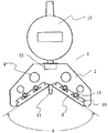
図1および図2において、1は本体部であり、本体部1は、ベース部材2と当接部材3とから構成されている。ベース部材2は、軽量化を図るために、つや消しアルマイト処理を施したアルミニウムから作製されている。また、作業現場での取り扱いを容易にするために、複数個の貫通穴4を穿設して、より軽量化を図ってある。 1 and 2,
図1乃至図3に示すように、ベース部材2には、所定の角度θで拡開した傾斜面5が設けられており、その傾斜面5には、組子式構造の嵌め込み溝6が形成されている。また、嵌め込み溝6が形成された傾斜面部分には、すり割溝7が設けられ、これらのすり割溝7の開口端と反対側には、すり割溝に連通する貫通穴8が穿設されている。また、図3(b)に示すように、これら貫通穴8の両端部は、テーパー加工9が施されている。 As shown in FIGS. 1 to 3, the
一方、図1乃至図3に示すように、当接部材3の一方の面は高精度な平面加工が施されており、他方の面側は上記ベース部材2のはめ込み溝6に勘合するように組子式の嵌め込み突起10が設けられている。上記ベース部材2の嵌め込み溝6および当接部材3の嵌め込み突起10は、いずれもワイヤカット加工により極めて高精度に加工されており、両者は極めて高い精度で嵌め合わせられるように作製されている。 On the other hand, as shown in FIGS. 1 to 3, one surface of the
ベース部材2の嵌め込み溝6に、当接部材3の嵌め込み突起を嵌め込むときには、はめ込み溝を広げる方向に力が働くので、ベース部材2に設けたすり割溝7の間隔を狭め、この部分によるクッション効果があるために、容易に嵌め込むことができる。一方、当接部材3がベース部材2に嵌め込まれた状態では、貫通穴8に皿ねじ14を挿入し、他側に設置した皿ナット等で締め付けることにより、テーパ加工部9の作用により、すり割溝7が押し広げられ、ベース部材2と当接部材3をしっかりと固着する。
本発明による外径測定器は、このように構成することにより、容易に当接部材を着脱できるために、従来は、測定器メーカに依頼していたメンテナンスが現場で容易に行うことができるという優れた効果を有している。When the fitting projection of the
Since the outer diameter measuring instrument according to the present invention is configured in this way, the contact member can be easily attached and detached, so that the maintenance that has been requested by the measuring instrument manufacturer can be easily performed on site. Has an excellent effect.
図1乃至図2において、11は測定子であり、ベース部材2に穿設された測定子取付け穴部12に挿入され、上記拡開角度θの2等分線上で移動するように設置されている。13は測定部であり、測定子11の先端と2つの当接部材3とが被測定物と3点で接したときの測定子の位置(移動量)に基づいて、被測定物の外径あるいは曲率を測定し、測定値を表示あるいは測定値を出力するものであり、例えば、デジタル式のインジケータを用いることにより、表示・記録等の作業を容易に行なうことができる。
なお、図1乃至図2には、測定部13としてデジタルインジケータを用いた例を示したが、測定子及び測定部として、ダイヤルゲージなど周知のものを用いることもできる。1 and 2,
1 and 2 show an example in which a digital indicator is used as the measuring
1 本体部
2 ベース部材
3 当接部材
4 貫通穴
5 傾斜面
6 嵌め込み溝
7 すり割り溝
8 貫通穴
9 テーパ加工部
10 嵌め込み突起
11 測定子
12 取付穴
13 測定部
14 皿ネジDESCRIPTION OF
Claims (7)
Priority Applications (1)
| Application Number | Priority Date | Filing Date | Title |
|---|---|---|---|
| JP2004145660A JP2005300508A (en) | 2004-04-14 | 2004-04-14 | Outer diameter measuring instrument |
Applications Claiming Priority (1)
| Application Number | Priority Date | Filing Date | Title |
|---|---|---|---|
| JP2004145660A JP2005300508A (en) | 2004-04-14 | 2004-04-14 | Outer diameter measuring instrument |
Publications (1)
| Publication Number | Publication Date |
|---|---|
| JP2005300508A true JP2005300508A (en) | 2005-10-27 |
Family
ID=35332181
Family Applications (1)
| Application Number | Title | Priority Date | Filing Date |
|---|---|---|---|
| JP2004145660A Pending JP2005300508A (en) | 2004-04-14 | 2004-04-14 | Outer diameter measuring instrument |
Country Status (1)
| Country | Link |
|---|---|
| JP (1) | JP2005300508A (en) |
Cited By (4)
| Publication number | Priority date | Publication date | Assignee | Title |
|---|---|---|---|---|
| JP2011501191A (en) * | 2007-10-25 | 2011-01-06 | ゼネラル・エレクトリック・カンパニイ | System and method for measuring mounting dimensions of a flow measurement system |
| CN103411512A (en) * | 2013-08-02 | 2013-11-27 | 奇瑞汽车股份有限公司 | Nominal diameter measuring instrument and measuring method for vacuum booster |
| CN103438785A (en) * | 2013-07-16 | 2013-12-11 | 东风朝阳朝柴动力有限公司 | Gauge for radius of semicircular thrust surface of engine body of diesel engine |
| CN113218282A (en) * | 2021-06-25 | 2021-08-06 | 河南柴油机重工有限责任公司 | Device and method for measuring small semicircular diameter of shaft part |
-
2004
- 2004-04-14 JP JP2004145660A patent/JP2005300508A/en active Pending
Cited By (4)
| Publication number | Priority date | Publication date | Assignee | Title |
|---|---|---|---|---|
| JP2011501191A (en) * | 2007-10-25 | 2011-01-06 | ゼネラル・エレクトリック・カンパニイ | System and method for measuring mounting dimensions of a flow measurement system |
| CN103438785A (en) * | 2013-07-16 | 2013-12-11 | 东风朝阳朝柴动力有限公司 | Gauge for radius of semicircular thrust surface of engine body of diesel engine |
| CN103411512A (en) * | 2013-08-02 | 2013-11-27 | 奇瑞汽车股份有限公司 | Nominal diameter measuring instrument and measuring method for vacuum booster |
| CN113218282A (en) * | 2021-06-25 | 2021-08-06 | 河南柴油机重工有限责任公司 | Device and method for measuring small semicircular diameter of shaft part |
Similar Documents
| Publication | Publication Date | Title |
|---|---|---|
| EP1959225A1 (en) | Circularity measuring device and tip end member quality judging method | |
| JP4764638B2 (en) | measuring device | |
| JP3643940B2 (en) | Measuring device | |
| JP2005300508A (en) | Outer diameter measuring instrument | |
| JP2011112608A (en) | Depth finder for minor defect within material | |
| JP5552925B2 (en) | Tire wear measurement system | |
| JP2010169601A (en) | Thickness measuring tool | |
| JP2004198350A (en) | Thickness meter | |
| CN104374277A (en) | Hole diameter measuring tool | |
| JP2009143443A (en) | Method and device for measuring abrasion amount of wheel | |
| JP2003028603A (en) | Dimension measuring device | |
| JP3869315B2 (en) | Measuring jig | |
| JP2007327874A (en) | Die lifetime determination device and die lifetime determination method | |
| JP2008002820A (en) | Dimension measuring instrument | |
| JP2008145282A (en) | Slide caliper for measurement | |
| GB2433120A (en) | Railway wheel diameter measuring tool | |
| JP6183484B2 (en) | Internal angle measuring tool | |
| RU2777696C1 (en) | Device for measuring geometric parameters of box-section wheel centers | |
| CN214372279U (en) | Thickness measuring device for corrosion metal component | |
| CN210268421U (en) | Measuring device | |
| JP4766470B2 (en) | Welding gauge for pressure measurement | |
| JP3129510U (en) | R caliper | |
| JP2005048844A (en) | Pre-load imposing method | |
| JP2006177713A (en) | Inspection/calibration artifact of shape measuring machine | |
| RU2301965C1 (en) | Device for measuring width of side shelves of corrugated sheets |