JP2005299980A - Water supply control apparatus and method - Google Patents
Water supply control apparatus and method Download PDFInfo
- Publication number
- JP2005299980A JP2005299980A JP2004114512A JP2004114512A JP2005299980A JP 2005299980 A JP2005299980 A JP 2005299980A JP 2004114512 A JP2004114512 A JP 2004114512A JP 2004114512 A JP2004114512 A JP 2004114512A JP 2005299980 A JP2005299980 A JP 2005299980A
- Authority
- JP
- Japan
- Prior art keywords
- water supply
- pump
- pressure
- control device
- water
- Prior art date
- Legal status (The legal status is an assumption and is not a legal conclusion. Google has not performed a legal analysis and makes no representation as to the accuracy of the status listed.)
- Granted
Links
Images
Landscapes
- Control Of Positive-Displacement Pumps (AREA)
- Air Conditioning Control Device (AREA)
Abstract
【課題】省エネルギー化を実現することができる送水制御装置および方法を提供する。
【解決手段】差圧センサ11により計測された末端差圧に基づいて二次ポンプ8−1〜3の送出圧力を設定し、この設定した送水圧力に基づいてポンプ8−1〜3のインバータ回転数とバイパス弁8の開度を制御することより、省エネルギー化を実現することができる。すなわち、従来では、インバータを導入することで流量が少ない場合でも送水圧力が一定となるので、ポンプの送水流量の減少による省エネルギーを実現した。これに対して、本実施の形態では、末端差圧に応じて送水圧力を変更するので、流量が少ないときには送水圧力を少なくできる。したがって、ポンプ揚程にかかるエネルギーも削減することが可能となり、結果として、さらなる省エネルギー化を実現することできる。
【選択図】 図1
A water supply control device and method capable of realizing energy saving are provided.
A delivery pressure of a secondary pump 8-1 to 3 is set based on a terminal differential pressure measured by a differential pressure sensor 11, and an inverter rotation of the pump 8-1 to 3 is set based on the set water supply pressure. By controlling the number and the opening degree of the bypass valve 8, energy saving can be realized. That is, conventionally, by introducing an inverter, the water supply pressure is constant even when the flow rate is small, and thus energy saving is realized by reducing the pump water supply flow rate. On the other hand, in this embodiment, since the water supply pressure is changed according to the terminal differential pressure, the water supply pressure can be reduced when the flow rate is small. Therefore, the energy required for the pump head can be reduced, and as a result, further energy saving can be realized.
[Selection] Figure 1
Description
本発明は、熱源機器の送水制御装置およびその制御方法に関し、より具体的には、熱源機器により生成された冷温水を負荷機器へ送出するポンプ等の動作を制御する送水制御装置およびその制御方法に関する。 The present invention relates to a water supply control device for a heat source device and a control method thereof, and more specifically, a water supply control device for controlling the operation of a pump or the like that sends cold / hot water generated by the heat source device to a load device, and a control method therefor About.
従来、空調システムにおける熱源機器で生成した冷温水をファンコイルユニットや空調機等の負荷機器に送出するポンプの制御は、送水圧制御や推定末端圧制御等で行われている。
吐出圧制御とは、ポンプの送水圧力が一定となるようにポンプのインバータ回転数を制御するものである。(例えば、特許文献1参照。)。
推定末端圧制御とは、流量に応じてポンプの送水圧力の設定値を変更し、この変更した送水圧力でポンプのインバータ回転数を制御するものである(例えば、特許文献2参照。)。
なお、出願人は、本明細書に記載した先行技術文献情報で特定される先行技術文献以外には、本発明に関連する先行技術文献を出願時までに発見するには至らなかった。
In the discharge pressure control, the inverter rotation speed of the pump is controlled so that the water supply pressure of the pump becomes constant. (For example, refer to Patent Document 1).
The estimated terminal pressure control is to change the set value of the pump water supply pressure in accordance with the flow rate, and to control the inverter rotation speed of the pump with this changed water supply pressure (see, for example, Patent Document 2).
The applicant has not yet found prior art documents related to the present invention by the time of filing other than the prior art documents specified by the prior art document information described in this specification.
しかしながら、従来の方法では、次のような問題があった。
送水圧制御では、流量が少ないときに吐出圧力が過剰となるので、エネルギー消費量が増大する。
推定末端圧制御では、送水圧力が建物の配管等の特性に影響されるので、流量のみからエネルギー消費量の少ない最適な送水圧力を設定するのは困難である。また、空調機が複数ある場合には、例えば一部の空調機だけが運転しているので流量が少ないのか、または全体的に流量が少ないかなど、空調機の運転状況によって流量の推定曲線が異なるので、流量のみから最適な送水圧力を設定するのは困難である。
そこで、本発明は、上述したような課題を解決するためになされたものであり、省エネルギー化を実現することができる送水制御装置およびその方法を提供することを目的とする。
However, the conventional method has the following problems.
In the water supply pressure control, since the discharge pressure becomes excessive when the flow rate is small, the energy consumption increases.
In the estimated terminal pressure control, since the water supply pressure is affected by the characteristics of the building piping and the like, it is difficult to set an optimum water supply pressure with less energy consumption from only the flow rate. In addition, when there are multiple air conditioners, for example, only some of the air conditioners are operating, so the flow rate estimation curve depends on the operating condition of the air conditioner, such as whether the flow rate is low or the overall flow rate is low. Since it is different, it is difficult to set the optimal water supply pressure only from the flow rate.
Then, this invention is made | formed in order to solve the above subjects, and it aims at providing the water-feeding control apparatus which can implement | achieve energy saving, and its method.
上述したような課題を解決するために、本発明にかかる送水制御装置は、熱源機により生成された冷温水を負荷機器に送出する送水制御装置において、負荷機器からの還水に圧力を付加した送水を負荷機器に送出するポンプと、還水が入力されるポンプの入力側と送水が出力されるポンプの出力側とを接続するバイパスに設けられたバイパス弁と、末端の負荷機器に入力される送水の圧力を計測するセンサと、このセンサにより計測される圧力に基づいて、ポンプから出力される送水の圧力を設定する制御装置とを備えたことを特徴とする。ここで、センサにより計測される圧力としては、負荷機器に入力される送水の圧力、または、負荷機器に入力される送水と負荷機器から出力される還水との差圧等を意味する。 In order to solve the above-described problems, the water supply control device according to the present invention adds pressure to the return water from the load device in the water supply control device that sends the cold / hot water generated by the heat source device to the load device. A bypass valve provided in the bypass that connects the pump that sends the water supply to the load device, the input side of the pump to which the return water is input, and the output side of the pump that outputs the water supply, and the input to the load device at the end And a control device for setting the water supply pressure output from the pump based on the pressure measured by the sensor. Here, the pressure measured by the sensor means the pressure of water supplied to the load device or the differential pressure between the water input to the load device and the return water output from the load device.
上記送水制御装置において、制御装置は、設定した送水の圧力に基づいて、ポンプの回転数およびバイパス弁の開度を制御するようにしてもよい。 In the water supply control device, the control device may control the rotational speed of the pump and the opening degree of the bypass valve based on the set water supply pressure.
上記送水制御装置において、ポンプの出力側の送水の圧力を計測する圧力センサをさらに備え、制御装置は、圧力センサにより計測される圧力を用いてポンプの回転数およびバイパス弁の開度を制御するようにしてもよい。
また、還水と送水の圧力差を計測する差圧センサをさらに備え、制御装置は、差圧センサにより計測される圧力差を用いてポンプの回転数およびバイパス弁の開度を制御するようにしてもよい。
The water supply control device further includes a pressure sensor that measures the pressure of water supply on the output side of the pump, and the control device controls the rotational speed of the pump and the opening degree of the bypass valve using the pressure measured by the pressure sensor. You may do it.
Further, a differential pressure sensor for measuring the pressure difference between the return water and the water supply is further provided, and the control device controls the rotational speed of the pump and the opening degree of the bypass valve using the pressure difference measured by the differential pressure sensor. May be.
上記送水制御装置において、ポンプは、定速ポンプと制御装置により回転数が制御される変速ポンプとから構成され、制御装置は、定速ポンプと変速ポンプとを同時に運転する場合、変速ポンプの回転数の下限値を変更するようにしてもよい。ここで、定速ポンプとは、回転数が一定のポンプのことを意味する。また、変速ポンプとは、インバータが設置された回転数が可変のポンプのことを意味する。 In the above water supply control device, the pump is composed of a constant speed pump and a transmission pump whose number of rotations is controlled by the control device, and the control device rotates the transmission pump when the constant speed pump and the transmission pump are operated simultaneously. The lower limit of the number may be changed. Here, the constant speed pump means a pump having a constant rotation speed. The variable speed pump means a pump having a variable number of revolutions in which an inverter is installed.
上記送水制御装置において、センサによる計測値を通信回線を介して制御装置に送信する送信手段をさらに備えるようにしてもよい。 The water supply control device may further include transmission means for transmitting a measurement value by the sensor to the control device via a communication line.
本発明にかかる送水制御方法は、熱源機により生成された冷温水を負荷機器に送出する送水制御方法において、末端の負荷機器に入力される送水の圧力を計測する第1のステップと、このセンサにより計測される圧力に基づいて、還水に圧力を付加した送水を負荷機器に送出するポンプから出力される送水の圧力を設定する第2のステップとを備えることを特徴とする。ここで、計測される圧力としては、負荷機器に入力される送水の圧力、または、負荷機器に入力される送水と負荷機器から出力される還水との差圧等を意味する。 The water supply control method according to the present invention includes a first step of measuring a pressure of water supplied to the load device at the end in the water supply control method for sending cold / hot water generated by the heat source device to the load device, and this sensor. And a second step of setting a water supply pressure output from a pump that sends the water supply with the pressure added to the return water to the load device. Here, the measured pressure means the pressure of water supplied to the load device or the differential pressure between the water supplied to the load device and the return water output from the load device.
上記送水制御方法において、第2のステップにより設定された送水の圧力に基づいて、ポンプの回転数および還水が入力されるポンプの入力側と送水が出力されるポンプの出力側とを接続するバイパスに設けられたバイパス弁の開度を制御する第3のステップをさらに備えるようにしてもよい。 In the water supply control method, based on the water supply pressure set in the second step, an input side of the pump to which the rotation speed and return water of the pump are input and an output side of the pump from which the water supply is output are connected. You may make it further provide the 3rd step which controls the opening degree of the bypass valve provided in the bypass.
上記送水制御方法において、第3のステップは、ポンプの出力側の送水の圧力を計測する第4のステップと、この第4のステップにより計測された圧力を用いてポンプの回転数およびバイパス弁の開度を制御する第5のステップとを備えるようにしてもよい。
また、第3のステップは、還水と送水の圧力差を計測する第4のステップと、この第4のステップにより計測された圧力差を用いてポンプの回転数およびバイパス弁の開度を制御する第5のステップとを備えるようにしてもよい。
In the water supply control method, the third step includes a fourth step of measuring the pressure of the water supply on the output side of the pump, and the number of rotations of the pump and the bypass valve using the pressure measured in the fourth step. You may make it provide the 5th step which controls an opening degree.
The third step is a fourth step for measuring the pressure difference between the return water and the water supply, and the pressure difference measured by the fourth step is used to control the rotational speed of the pump and the opening of the bypass valve. And a fifth step.
上記送水制御方法において、ポンプが定速ポンプと第3のステップにより回転数が制御される変速ポンプとから構成され、定速ポンプと変速ポンプとを同時に運転する場合、変速ポンプの回転数の下限値を変更する第6のステップをさらに備えるようにしてもよい。ここで、定速ポンプとは、回転数が一定のポンプのことを意味する。また、変速ポンプとは、インバータが設置された回転数が可変のポンプのことを意味する。 In the above water supply control method, when the pump is composed of a constant speed pump and a transmission pump whose rotation speed is controlled by the third step, and the constant speed pump and the transmission pump are operated simultaneously, the lower limit of the rotation speed of the transmission pump. You may make it further provide the 6th step which changes a value. Here, the constant speed pump means a pump having a constant rotation speed. The variable speed pump means a pump having a variable number of revolutions in which an inverter is installed.
本発明によれば、末端の負荷機器に入力される送水の圧力に基づいてポンプから出力される送水の圧力を設定を変更することより、末端の負荷機器への送水圧力に応じた送水圧力の設定ができる。これにより、流量が多いときには送水圧力を多くし、流量が少ないときには送水圧力を少なくするといった流量に応じた送水圧力の制御が可能となる。したがって、ポンプ揚程にかかるエネルギーを削減することが可能となり、結果として、さらなる省エネルギー化を実現することができる。
また、本発明によれば、定速ポンプと変速ポンプとを同時に運転する場合に変速ポンプの回転数の下限値を変更することにより、定速ポンプと変速ポンプの送水圧力の差による締め切り運転を防ぐことができる。これにより、本発明を用いた空調システムでは、全てのポンプを変速ポンプする必要がないので、コストダウンを図ること可能となる。
また、本発明によれば、センサによる計測値を通信回線を介して制御装置に送信する送信手段を設けることにより、送信手段と制御装置とを離間して配設することが可能となる。これにより、ポンプが末端の負荷機器と離間した建造物においても、末端の負荷機器への送水の圧力に基づくポンプの制御が可能となる。
According to the present invention, by changing the setting of the water supply pressure output from the pump based on the water supply pressure input to the terminal load device, the water supply pressure corresponding to the water supply pressure to the terminal load device is changed. Can be set. This makes it possible to control the water supply pressure in accordance with the flow rate, such as increasing the water supply pressure when the flow rate is high and decreasing the water supply pressure when the flow rate is low. Therefore, the energy required for the pump head can be reduced, and as a result, further energy saving can be realized.
Further, according to the present invention, when the constant speed pump and the transmission pump are operated simultaneously, the lower limit value of the rotation speed of the transmission pump is changed, so that the deadline operation due to the difference in water supply pressure between the constant speed pump and the transmission pump is performed. Can be prevented. Thereby, in the air conditioning system using the present invention, it is not necessary to shift pumps for all the pumps, so that the cost can be reduced.
In addition, according to the present invention, it is possible to dispose the transmission unit and the control device separately by providing the transmission unit that transmits the measurement value obtained by the sensor to the control device via the communication line. Thereby, even in a building in which the pump is separated from the terminal load device, it is possible to control the pump based on the pressure of water supplied to the terminal load device.
[第1の実施の形態]
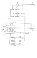
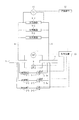
以下、図面を参照して、本発明の第1の実施の形態について詳細に説明する。図1は、本実施の形態かかる複式ポンプシステムの構成を示す計装図である。
[First Embodiment]
Hereinafter, a first embodiment of the present invention will be described in detail with reference to the drawings. FIG. 1 is an instrumentation diagram showing a configuration of a dual pump system according to the present embodiment.
本実施の形態にかかる複式ポンプシステムは、冷温水発生機、ヒートポンプ、冷凍機、ボイラー等の冷温水を生成する熱源機1−1〜3と、この熱源機1−1〜3の補機としての一次ポンプ2−1〜3と、往路ヘッダー3−1,3−2と、往水管路4と、ファンコイルユニットや空調機等の負荷機器5−1〜3と、還水管路6と、還路ヘッダー7と、往路ヘッダー3−1と3−2の間に設けられた二次ポンプ8−1〜3と、往路ヘッダー3−1と3−2の間に設けられたバイパス弁9と、送水圧力P1を計測する圧力センサ10と、末端差圧P2を計測する差圧センサ11と、末端差圧P2を後述する制御装置13に送信する送信装置12と、制御装置13とから構成される。ここで、二次ポンプ8−1,8−2は、それぞれインバータ8−1a、8−2aをそれぞれ備えている。
The dual pump system according to the present embodiment includes heat source devices 1-1 to 1-3 that generate cold / hot water such as a cold / hot water generator, a heat pump, a refrigerator, and a boiler, and auxiliary devices for the heat source devices 1-1 to 1-3. Primary pumps 2-1 to 2-3, outbound headers 3-1 and 3-2,
この複式ポンプシステムにおいて、ポンプ2−1〜3により圧送され熱源機1−1〜3により熱量が付加された冷温水(送水)は、往路ヘッダー3−1に送られ、二次ポンプ8−1〜3により圧送されて往路ヘッダー3−2を経て送水管路4に供給され、負荷機器5−1〜3を介し、還水管路6により還水としてヘッダー7に至り、再びポンプ2−1〜3によって圧送され、以上の経路を循環する。
In this dual pump system, cold / hot water (water supply) pumped by the pumps 2-1 to 3 and added with heat by the heat source units 1-1 to 1-3 is sent to the forward header 3-1, and the secondary pump 8-1. To 3 and supplied to the
ここで、送水圧力P1とは、二次ポンプ8−1〜3等により圧送されて送水管路4に送られた送水の圧力のことを意味する。
また、末端差圧P2とは、本実施の形態にかかる複式ポンプシステムが設けられた建造物の末端、すなわち送水管路4から送水が出力される側(負荷機器側)の最端部に設けられた負荷機器5−3に入力される送水と、負荷機器5−3から出力される還水の圧力差のことを意味する。
Here, the water supply pressure P1 means the pressure of water supplied by the secondary pumps 8-1 to 3 and the like and sent to the
Further, the terminal differential pressure P2 is provided at the end of the building where the dual pump system according to the present embodiment is provided, that is, at the extreme end on the side where the water supply is output from the water supply conduit 4 (load equipment side). This means a difference in pressure between water input to the load device 5-3 and return water output from the load device 5-3.
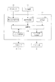
図1に示す制御装置13の構成について、図2を参照して説明する。図2は、制御装置13の構成を示すブロック図である。
制御装置13は、圧力センサ10が計測した送水圧力P1を受信する送水圧力受信部13aと、差圧センサ11が計測した末端差圧P2を送信装置12を介して受信する差圧受信部13bと、ユーザの操作入力や末端の負荷機器の設定温度等により末端差圧設定値P2set設定する設定部13cと、送水圧力受信部13aが受信した送水圧力P1と差圧受信部13bが受信した差圧P2と設定部13cにより設定された末端差圧設定値P2setに基づいて二次ポンプ8−1,2のインバータ回転数およびバイパス弁9の開度を演算する演算部13dと、演算部13dの演算結果に基づきインバータ8−1a,2aを介して二次ポンプ8−1,2の回転数(以下、インバータ回転数という)を制御するポンプ制御部13eと、演算部13cの演算結果に基づいてバイパス弁9の開度を制御するバイパス弁制御部13fとを有する。
ここで、ポンプ制御部13eは、設定部13cを介してのユーザによる操作入力または演算部13dの演算結果に基づいて、二次ポンプ8−3のON/OFFに関する動作制御を行う。また、ポンプ制御部13eは、二次ポンプ8−1〜3の運転状況に関する情報を演算部13dに送信する。
The configuration of the
The
Here, the
このような制御装置13は、CPU等の演算装置、メモリ、HDD等の記憶装置、有線または無線を介して複式ポンプシステムの各構成要素と情報の送受を行うI/F装置、CRT(Cathode Ray Tube)、LCD(Liquid Crystal Display)またはFED(Field Emission Display)等の表示装置などを備えたコンピュータと、このコンピュータにインストールされたプログラムとからそれぞれ構成されており、上記ハードウェア装置がプログラムによって制御されることによって、すなわちハードウェア資源とソフトウェアが協働することによって、上述した送水圧力受信部13a、差圧受信部13b、設定部13c、演算部13d、ポンプ制御部13eおよびバイパス弁制御部13fが実現される。
The
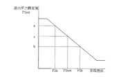
次に、本実施の形態にかかる複式ポンプシステムの動作について、図1〜4を参照して説明する。図3は、送水圧力と末端差圧の関係を説明する図、図4は、インバータ回転数およびバイパス弁開度と送水圧力の関係を説明する図である。
本実施の形態にかかる複式ポンプシステムは、末端差圧P2に基づいて送水圧力を設定し、この設定した送水圧力に基づいて二次ポンプ8−1,2のインバータ回転数とバイパス弁9の開度を制御するものである。
Next, the operation of the dual pump system according to the present embodiment will be described with reference to FIGS. FIG. 3 is a diagram illustrating the relationship between the water supply pressure and the terminal differential pressure, and FIG. 4 is a diagram illustrating the relationship between the inverter rotational speed, the bypass valve opening degree, and the water supply pressure.
In the dual pump system according to the present embodiment, the water supply pressure is set based on the terminal differential pressure P2, and based on the set water supply pressure, the inverter rotational speed of the secondary pumps 8-1, 2 and the
まず、制御装置13は、図3に示すように、ユーザや末端の負荷機器の設定温度等により設定された末端差圧設定値P2setに基づいて、PID制御で送水圧力を設定する。
差圧センサ11により計測された末端差圧P2が、末端差圧設定値P2setよりも小さい場合、P動作(比例動作)により送水圧力を大きく設定する。
一方、差圧センサ11により計測された末端差圧P2が、末端差圧設定値P2setよりも大きい場合、P動作により送水圧力を小さく設定する。
First, as shown in FIG. 3, the
When the terminal differential pressure P2 measured by the
On the other hand, when the terminal differential pressure P2 measured by the
例えば、図3において、差圧センサ11により計測された末端差圧が末端差圧設定値P2setよりも小さい末端差圧P2aの場合は、送水圧力が大きくなれば末端差圧P2aも大きくなるので、送水圧力設定値を末端差圧設定値P2setに対応する送水圧力xよりも大きい送水圧力aに設定する。
また、図3において、差圧センサ11により計測された末端差圧が末端差圧設定値P2setよりも大きい末端差圧P2aの場合は、送水圧力が大きくなれば末端差圧P2aも大きくなるので、送水圧力設定値を末端差圧設定値P2setに対応する送水圧力xよりも小さい送水圧力bに設定する。
For example, in FIG. 3, in the case where the terminal differential pressure P2a measured by the
Further, in FIG. 3, in the case of the terminal differential pressure P2a in which the terminal differential pressure measured by the
また、I動作(積分動作)により偏差がなくなるので、現在の末端差圧P2が末端差圧設定値P2setよりも小さいときには送出圧力の設定値はさらに大きくなり、現在の末端差圧計測値が設定値よりも大きいときには送出圧力はさらに小さくなる。 Further, since there is no deviation due to the I operation (integration operation), when the current terminal differential pressure P2 is smaller than the terminal differential pressure setting value P2set, the set value of the delivery pressure is further increased, and the current terminal differential pressure measurement value is set. When larger than the value, the delivery pressure is further reduced.
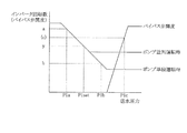
次に、制御装置13は、図4に示すように、上述したように設定した送水圧力設定値P1setに基づいて、二次ポンプ8−1,2のインバータ回転数およびバイパス弁9の開度を設定する。
圧力センサ10により計測された送水圧力P1が、送水圧力設定値P1setよりも小さい場合、インバータ回転数を大きく設定する。
一方、圧力センサ10により計測された送水圧力P1が、送水圧力設定値P1setよりも大きい場合、インバータ回転数を小さく設定する。
また、圧力センサ10により計測された送水圧力P1が、送水圧力設定値P1setよりもさらに大きく、インバータ回転数を下限値にしても送出圧力設定値P1setに達しない場合、バイパス弁9を送水圧力P1の程度に応じて開放する。
Next, as shown in FIG. 4, the
When the water supply pressure P1 measured by the
On the other hand, when the water supply pressure P1 measured by the
Further, when the water supply pressure P1 measured by the
例えば、図4において、圧力センサ10により計測された送水圧力が送水圧力設定値P1setよりも小さい送水圧力P1aの場合は、インバータ回転数を上げれば送出圧力が大きくなるので、インバータ回転数を送水圧力設定値P1setに対応する送水圧力yよりも大きいインバータ回転数aに設定する。
また、図4において、圧力センサ10により計測された送水圧力が送水圧力設定値P1setよりも大きい送水圧力P1bの場合は、インバータ回転数を下げれば送出圧力が小さくなるので、インバータ回転数を送水圧力設定値P1setに対応する送水圧力yよりも小さいインバータ回転数bに設定する。
さらに、図4において、圧力センサ10により計測された送水圧力が送水圧力設定値P1setよりもさらに大きい送水圧力P1cの場合は、インバータ回転数が既に下限値に達しているためバイパス弁9を開くことにより送出圧力を下げる。したがって、バイパス弁の開度を開度cに設定する。
For example, in FIG. 4, when the water supply pressure measured by the
Further, in FIG. 4, when the water supply pressure measured by the
Furthermore, in FIG. 4, when the water supply pressure measured by the
ここで、インバータ回転数の下限値は二次ポンプ8−1〜3の運転状況によって切り替える。具体的には、インバータ付きのポンプ(本実施の形態では二次ポンプ8−1,2)だけが運転しているとき(図4中のポンプ単独運転時)と、インバータ付きポンプとインバータ未設置のポンプ(本実施の形態では二次ポンプ8−3)が同時に運転しているとき(図4中のポンプ並列運転時)とで、下限値を切り替える。この下限値の切替は、ポンプ制御部13eから受信するインバータ未設置のポンプの運転状況に基づいて、演算部13dにより行われる。
なお、インバータ未設置のポンプは、送水圧力が定格値(最大値)で常に運転されている。
Here, the lower limit value of the inverter rotational speed is switched depending on the operation status of the secondary pumps 8-1 to 8-3. Specifically, when only the pump with an inverter (secondary pumps 8-1 and 2 in this embodiment) is operating (during pump independent operation in FIG. 4), the pump with the inverter and the inverter are not installed. The lower limit value is switched when the pump (secondary pump 8-3 in the present embodiment) is operating simultaneously (during pump parallel operation in FIG. 4). The lower limit value is switched by the
Note that a pump without an inverter is always operated with a water supply pressure at a rated value (maximum value).
末端圧力で直接にインバータ回転数とバイパス弁を制御する場合は、並列運転時にインバータ付きポンプとインバータ無しポンプとの間に送水圧力の差が生じる。例えば、インバータ回転数を下げすぎると、インバータ無しのポンプは定格値で運転しているため、インバータ付きポンプの送水圧力がインバータ無しポンプの送水圧力よりも小さくなり、インバータ付きポンプから水が流れない締め切り運転をする恐れがある。この締め切り運転を防止するためには、全てのポンプにインバータを設置する必要があった。 When the inverter speed and the bypass valve are directly controlled by the end pressure, a difference in water supply pressure occurs between the pump with the inverter and the pump without the inverter during parallel operation. For example, if the inverter speed is reduced too much, the pump without inverter operates at the rated value, so the water supply pressure of the pump with inverter becomes smaller than the water supply pressure of the pump without inverter, and water does not flow from the pump with inverter. There is a risk of deadline operation. In order to prevent this deadline operation, it was necessary to install inverters in all the pumps.
これに対して、本実施の形態では、末端圧力に基づいて直接に送水圧力を変更するのではなく、末端圧力に基づいて送水圧力の設定値を変更する。このため、上述したようにポンプの単独運転時と並列運転時とでインバータ回転数の下限値を切り替えることで、上記締め切り運転を防ぐことが可能となる。したがって、本実施の形態によれば、全てのポンプにインバータを設置しなくてよいので、コストダウンを図ることができる。 In contrast, in the present embodiment, the water supply pressure is not directly changed based on the end pressure, but the set value of the water supply pressure is changed based on the end pressure. For this reason, it becomes possible to prevent the above-mentioned deadline operation by switching the lower limit value of the inverter rotation speed between the single operation and the parallel operation of the pump as described above. Therefore, according to the present embodiment, it is not necessary to install inverters in all the pumps, so that the cost can be reduced.
このように、本実施の形態によれば、末端差圧に基づいて二次ポンプ8−1〜3の送出圧力を設定し、この設定した送水圧力に基づいてポンプ8−1〜3のインバータ回転数とバイパス弁9の開度を制御することより、省エネルギー化を実現することができる。
すなわち、従来では、インバータを導入することで流量が少ない場合でも送水圧力が一定となるので、ポンプの送水流量を減らすことによる省エネルギーを実現した。これに対して、本実施の形態では、末端差圧に応じて送水圧力を変更するので、流量が少ないときには送水圧力を少なくできる。したがって、ポンプ揚程にかかるエネルギーも削減することが可能となり、結果として、さらなる省エネルギー化を実現することできる。
Thus, according to the present embodiment, the delivery pressure of the secondary pumps 8-1 to 3-3 is set based on the terminal differential pressure, and the inverter rotation of the pumps 8-1 to 3-3 is set based on the set water supply pressure. By controlling the number and the opening degree of the
That is, conventionally, by introducing an inverter, the water supply pressure becomes constant even when the flow rate is small, and thus energy saving is realized by reducing the pump water supply flow rate. On the other hand, in this embodiment, since the water supply pressure is changed according to the terminal differential pressure, the water supply pressure can be reduced when the flow rate is small. Therefore, the energy required for the pump head can be reduced, and as a result, further energy saving can be realized.
なお、本実施の形態において、送信装置12は、末端の負荷機器(図1に示す負荷機器5−3)の近傍、例えば本実施の形態にかかる複式ポンプシステムが設けられた建造物中の同じフロアなどに設けられる。
また、制御装置13は、二次ポンプ8−1〜3の近傍、例えば上記建造物中の同じフロアなどに設けられる。
このような送信装置12と制御装置13とは、有線や無線などの通信回線により接続される。したがって、差圧センサ11により計測され送信装置12に入力された末端差圧P2は、上記通信回線を介して、制御装置13に送信される。
このように本実施の形態によれば、送信装置12と制御装置13とは離間して配設することができるので、本実施の形態にかかる複式ポンプシステムを配設する建造物の規模にかかわらずポンプの制御が可能となる。
In the present embodiment, the
The
Such a
As described above, according to the present embodiment, the
また、本実施の形態では、末端の負荷機器の差圧に基づいて送水圧力を制御するようにしているが、末端の負荷機器に入力される送水の圧力(末端圧力)に基づいて送水圧力を制御するようにしてもよい。
また、本実施の形態では、送水圧力P1に基づいて二次ポンプ8−1のインバータ回転数およびバイパス弁9の開度を設定するようにしてるが、ヘッダー間(図1ではヘッダー3−1とヘッダー3−2との間)の差圧に基づいて、上記インバータ回転数およびバイパス弁9の開度を設定するようにしてもよい。
In this embodiment, the water supply pressure is controlled based on the differential pressure of the terminal load device, but the water supply pressure is controlled based on the water supply pressure (terminal pressure) input to the terminal load device. You may make it control.
In the present embodiment, the inverter rotational speed of the secondary pump 8-1 and the opening degree of the
[第2の実施の形態]
次に、本発明の第2の実施の形態について詳細に説明する。図5は、本実施の形態かかる単式ポンプシステムの構成を示す計装図である。なお、図1で説明した複式ポンプシステムと同等の構成要素には同じ名称および符号を付し、適宜説明を省略する。
同図において、単式ポンプシステムには、往路ヘッダー3と還路ヘッダー7とを接続するバイパス管路の途上にバイパス弁9と差圧計14が設けられている。この単式ポンプシステムにおいて、一次ポンプ2−1〜3により圧送されて熱源機1−1〜3により熱量が付加された冷温水(送水)は、往路ヘッダー3を経て送水管路4に供給され、負荷機器5−1〜3を介し、還水管路6により還水として往路ヘッダー7に至り、再び一次ポンプ2−1〜3によって圧送され、以上の経路を循環する。ここで、一次ポンプ2−1,2−2は、それぞれインバータ2−1a、2−2aをそれぞれ備えている。
[Second Embodiment]
Next, a second embodiment of the present invention will be described in detail. FIG. 5 is an instrumentation diagram showing a configuration of a single pump system according to the present embodiment. In addition, the same name and code | symbol are attached | subjected to the component equivalent to the dual pump system demonstrated in FIG. 1, and description is abbreviate | omitted suitably.
In the figure, the single-type pump system is provided with a
本実施の形態にかかる単式ポンプシステムは、末端差圧P2に基づいてヘッダー間差圧を設定し、この設定した送水圧力に基づきインバータ2−1a,2aを介して一次ポンプ2−1,2の回転数(以下、インバータ回転数という)とバイパス弁9の開度を制御するものである。
ここで、ヘッダー間差圧とは、往路ヘッダー3と還路ヘッダー7との間の差圧、すなわち往路ヘッダー3から往水還路4に送出される往水と還水管路6から還路ヘッダー7に送出される還水の圧力差を意味する。本実施の形態では、第1の実施の形態の圧力センサ10により計測される送水差圧P1の替わりに、差圧計14により計測される差圧DPを用いて一次ポンプ2−1〜3のインバータ回転数とバイパス弁9の開度を制御する。
The single pump system according to the present embodiment sets the header differential pressure based on the terminal differential pressure P2, and based on the set water supply pressure, the primary pumps 2-1 and 2 are connected via the inverters 2-1a and 2a. The number of revolutions (hereinafter referred to as inverter revolution number) and the opening degree of the
Here, the inter-header differential pressure is the differential pressure between the
本実施の形態においても、末端差圧P2に基づいてヘッダー間差圧を設定し、この設定した差圧に基づき差圧計14により計測される差圧DPを用いて一次ポンプ2−1,2のインバータ回転数とバイパス弁9の開度を制御することにより、上述した第1の実施の形態と同様の効果が得られる。
Also in the present embodiment, the inter-header differential pressure is set based on the terminal differential pressure P2, and the primary pumps 2-1 and 2-2 are configured using the differential pressure DP measured by the
なお、本実施の形態においても、第1の実施の形態と同様、送信装置12と制御装置13とは離間して配設するようにしてもよい。これにより、本実施の形態にかかる単式ポンプシステムを配設する建造物の規模にかかわらずポンプの制御が可能となる。
Also in the present embodiment, as in the first embodiment, the
なお、第1および第2の実施の形態において、熱源機、一次ポンプ、二次ポンプ、インバータおよび負荷機器の数量は、上述した数量に限定されず、適宜自由に設定することができる。 In the first and second embodiments, the numbers of the heat source device, the primary pump, the secondary pump, the inverter, and the load device are not limited to the above-described numbers, and can be freely set as appropriate.
1−1〜3…熱源機、2−1〜3…一次ポンプ、2−1a〜2−2a…インバータ、3,3−1,3−2…往路ヘッダー、4…往水管路、5−1〜3…負荷機器、6…還水管路、7…管路ヘッダー、8−1〜3…二次ポンプ、8−1a〜8−2a…インバータ、9…バイパス弁、10…圧力センサ、11…差圧センサ、12…入力装置、13…制御装置、13a…送水圧力受信部、13b…差圧受信部、13c…設定部、13d…演算部、13e…ポンプ制御部、13f…バイパス弁制御部、14…差圧計。
1-1-3 ... Heat source machine, 2-1-3 ... Primary pump, 2-1a-2-2a ... Inverter, 3, 3-1, 3-2 ... Outbound header, 4 ... Outbound pipeline, 5-1 DESCRIPTION OF SYMBOLS -3 ... Load equipment, 6 ... Return water pipe, 7 ... Pipe line header, 8-1-3 ... Secondary pump, 8-1a-8-2a ... Inverter, 9 ... Bypass valve, 10 ... Pressure sensor, 11 ... Differential pressure sensor, 12 ... Input device, 13 ... Control device, 13a ... Water pressure receiving unit, 13b ... Differential pressure receiving unit, 13c ... Setting unit, 13d ... Calculating unit, 13e ... Pump control unit, 13f ... Bypass valve control unit , 14 ... Differential pressure gauge.
Claims (11)
前記負荷機器からの還水に圧力を付加した送水を前記負荷機器に送出するポンプと、
前記還水が入力される前記ポンプの入力側と前記送水が出力される前記ポンプの出力側とを接続するバイパスに設けられたバイパス弁と、
末端の前記負荷機器に入力される送水の圧力を計測するセンサと、
このセンサにより計測される前記圧力に基づいて、前記ポンプから出力される前記送水の圧力を設定する制御装置と
を備えたことを特徴とする送水制御装置。 In the water supply control device that sends the cold / hot water generated by the heat source machine to the load equipment,
A pump for sending water to the load device with pressure applied to the return water from the load device;
A bypass valve provided in a bypass connecting the input side of the pump to which the return water is input and the output side of the pump from which the water supply is output;
A sensor for measuring the pressure of water supplied to the load device at the end;
A water supply control device comprising: a control device that sets the pressure of the water supply output from the pump based on the pressure measured by the sensor.
ことを特徴とする請求項1記載の送水制御装置。 The water supply control device according to claim 1, wherein the control device controls the rotation speed of the pump and the opening degree of the bypass valve based on the set water supply pressure.
前記制御装置は、前記圧力センサにより計測される前記圧力を用いて前記ポンプの回転数および前記バイパス弁の開度を制御する
ことを特徴とする請求項2記載の送水制御装置。 A pressure sensor for measuring the pressure of the water supply on the output side of the pump;
The water supply control device according to claim 2, wherein the control device controls the rotation speed of the pump and the opening of the bypass valve using the pressure measured by the pressure sensor.
前記制御装置は、前記差圧センサにより計測される前記圧力差を用いて前記ポンプの回転数および前記バイパス弁の開度を制御する
ことを特徴とする請求項2記載の送水制御装置。 Further comprising a differential pressure sensor for measuring a pressure difference between the return water and the water supply;
The water supply control device according to claim 2, wherein the control device controls the rotation speed of the pump and the opening degree of the bypass valve using the pressure difference measured by the differential pressure sensor.
前記制御装置は、前記定速ポンプと前記変速ポンプとを同時に運転する場合、前記変速ポンプの回転数の下限値を変更する
ことを特徴とする請求項2乃至4のいずれか1項に記載の送水制御装置。 The pump is composed of a constant speed pump and a variable speed pump whose rotational speed is controlled by the control device,
5. The control device according to claim 2, wherein when the constant speed pump and the speed change pump are operated simultaneously, the control device changes a lower limit value of the rotation speed of the speed change pump. 6. Water supply control device.
ことを特徴とする請求項1乃至5のいずれか1項に記載の送水制御装置。 The water supply control device according to any one of claims 1 to 5, further comprising transmission means for transmitting a measurement value obtained by the sensor to the control device via a communication line.
末端の前記負荷機器に入力される送水の圧力を計測する第1のステップと、
このセンサにより計測される前記圧力に基づいて、前記還水に圧力を付加した前記送水を前記負荷機器に送出するポンプから出力される前記送水の圧力を設定する第2のステップと
を備えることを特徴とする送水制御方法。 In a water supply control method for sending cold / hot water generated by a heat source machine to a load device,
A first step of measuring the pressure of water input to the load device at the end;
Based on the pressure measured by the sensor, a second step of setting the water supply pressure output from a pump that sends the water supply with pressure added to the return water to the load device. A characteristic water supply control method.
をさらに備えることを特徴とする請求項7記載の送水制御方法。 Based on the pressure of the water supply set in the second step, the rotation speed of the pump and the input side of the pump to which the return water is input and the output side of the pump to which the water supply is output are connected The water supply control method according to claim 7, further comprising a third step of controlling an opening degree of a bypass valve provided in the bypass.
前記ポンプの出力側の前記送水の圧力を計測する第4のステップと、
この第4のステップにより計測された前記圧力を用いて前記ポンプの回転数および前記バイパス弁の開度を制御する第5のステップと
を備えることを特徴とする請求項8記載の送水制御方法。 The third step includes
A fourth step of measuring the pressure of the water supply on the output side of the pump;
The water supply control method according to claim 8, further comprising: a fifth step of controlling the number of rotations of the pump and the opening of the bypass valve using the pressure measured in the fourth step.
前記還水と前記送水の圧力差を計測する第4のステップと、
この第4のステップにより計測された前記圧力差を用いて前記ポンプの回転数および前記バイパス弁の開度を制御する第5のステップと
を備えることを特徴とする請求項8記載の送水制御方法。 The third step includes
A fourth step of measuring a pressure difference between the return water and the water supply;
The water supply control method according to claim 8, further comprising: a fifth step of controlling the rotation speed of the pump and the opening of the bypass valve using the pressure difference measured in the fourth step. .
をさらに備えることを特徴とする請求項8乃至10のいずれか1項に記載の送水制御装置。
When the pump is composed of a constant speed pump and a variable speed pump whose rotational speed is controlled by the third step, and the constant speed pump and the variable speed pump are operated simultaneously, the lower limit value of the rotational speed of the variable speed pump The water supply control device according to any one of claims 8 to 10, further comprising a sixth step of changing the value.
Priority Applications (1)
| Application Number | Priority Date | Filing Date | Title |
|---|---|---|---|
| JP2004114512A JP4426363B2 (en) | 2004-04-08 | 2004-04-08 | Water supply control apparatus and method |
Applications Claiming Priority (1)
| Application Number | Priority Date | Filing Date | Title |
|---|---|---|---|
| JP2004114512A JP4426363B2 (en) | 2004-04-08 | 2004-04-08 | Water supply control apparatus and method |
Publications (2)
| Publication Number | Publication Date |
|---|---|
| JP2005299980A true JP2005299980A (en) | 2005-10-27 |
| JP4426363B2 JP4426363B2 (en) | 2010-03-03 |
Family
ID=35331728
Family Applications (1)
| Application Number | Title | Priority Date | Filing Date |
|---|---|---|---|
| JP2004114512A Expired - Fee Related JP4426363B2 (en) | 2004-04-08 | 2004-04-08 | Water supply control apparatus and method |
Country Status (1)
| Country | Link |
|---|---|
| JP (1) | JP4426363B2 (en) |
Cited By (10)
| Publication number | Priority date | Publication date | Assignee | Title |
|---|---|---|---|---|
| JP2009030821A (en) * | 2007-07-24 | 2009-02-12 | Yamatake Corp | Water supply control system and water supply control method |
| JP2009121722A (en) * | 2007-11-13 | 2009-06-04 | Yamatake Corp | Water pressure control system and water pressure control method |
| JP2009236465A (en) * | 2008-03-28 | 2009-10-15 | Yamatake Corp | Water supply pressure control system and method |
| JP2009300033A (en) * | 2008-06-16 | 2009-12-24 | Toenec Corp | Controller for air-conditioning secondary pump |
| JP2011112277A (en) * | 2009-11-26 | 2011-06-09 | Yamatake Corp | System and method for controlling water supply pressure |
| JP2011153809A (en) * | 2010-01-28 | 2011-08-11 | Arefu Net:Kk | Heat source control system and heat source control method |
| JP2011214442A (en) * | 2010-03-31 | 2011-10-27 | Yamatake Corp | System and method for water supply pressure control |
| TWI615212B (en) * | 2015-02-09 | 2018-02-21 | 東芝三菱電機產業系統股份有限公司 | Descaling system, control device of the same, and control method |
| WO2018225221A1 (en) * | 2017-06-08 | 2018-12-13 | 三菱電機株式会社 | Heat source system |
| CN112432326A (en) * | 2020-11-19 | 2021-03-02 | 珠海格力电器股份有限公司 | Control method and device of refrigeration secondary pump, air conditioning system, medium and processor |
-
2004
- 2004-04-08 JP JP2004114512A patent/JP4426363B2/en not_active Expired - Fee Related
Cited By (12)
| Publication number | Priority date | Publication date | Assignee | Title |
|---|---|---|---|---|
| JP2009030821A (en) * | 2007-07-24 | 2009-02-12 | Yamatake Corp | Water supply control system and water supply control method |
| KR101022295B1 (en) * | 2007-07-24 | 2011-03-21 | 가부시키가이샤 야마다케 | Water control device and water control method |
| JP2009121722A (en) * | 2007-11-13 | 2009-06-04 | Yamatake Corp | Water pressure control system and water pressure control method |
| JP2009236465A (en) * | 2008-03-28 | 2009-10-15 | Yamatake Corp | Water supply pressure control system and method |
| JP2009300033A (en) * | 2008-06-16 | 2009-12-24 | Toenec Corp | Controller for air-conditioning secondary pump |
| JP2011112277A (en) * | 2009-11-26 | 2011-06-09 | Yamatake Corp | System and method for controlling water supply pressure |
| JP2011153809A (en) * | 2010-01-28 | 2011-08-11 | Arefu Net:Kk | Heat source control system and heat source control method |
| JP2011214442A (en) * | 2010-03-31 | 2011-10-27 | Yamatake Corp | System and method for water supply pressure control |
| TWI615212B (en) * | 2015-02-09 | 2018-02-21 | 東芝三菱電機產業系統股份有限公司 | Descaling system, control device of the same, and control method |
| WO2018225221A1 (en) * | 2017-06-08 | 2018-12-13 | 三菱電機株式会社 | Heat source system |
| US11187439B2 (en) | 2017-06-08 | 2021-11-30 | Mitsubishi Electric Corporation | Heat source system |
| CN112432326A (en) * | 2020-11-19 | 2021-03-02 | 珠海格力电器股份有限公司 | Control method and device of refrigeration secondary pump, air conditioning system, medium and processor |
Also Published As
| Publication number | Publication date |
|---|---|
| JP4426363B2 (en) | 2010-03-03 |
Similar Documents
| Publication | Publication Date | Title |
|---|---|---|
| JP2009030821A (en) | Water supply control system and water supply control method | |
| US10488126B2 (en) | Valve control in an HVAC system with sensors | |
| JP3917835B2 (en) | Pressurized water pump system | |
| JP5209244B2 (en) | Air conditioning control system and air conditioning control method | |
| JP4426363B2 (en) | Water supply control apparatus and method | |
| EP2837898B1 (en) | Air-conditioning system | |
| US20210293432A1 (en) | Environmental Control Unit including Maintenance Prediction | |
| JP4173973B2 (en) | Number control device and number control method for heat source equipment | |
| JP2008070067A (en) | Apparatus and method for determining the number of operating refrigerators | |
| JP6295227B2 (en) | Turbine flow controller | |
| JP4249591B2 (en) | Primary pump type heat source variable flow rate control system and primary pump minimum flow rate securing method | |
| CN104913464A (en) | Thermal Source Instrument Controlling Device and Air-Conditioning System | |
| JP2009019842A (en) | Water supply control system and water supply control method | |
| JP5015523B2 (en) | Heat source machine operation control method and apparatus | |
| CN101354591A (en) | Information display device and information display method for flow control valve | |
| EP2085706B1 (en) | Hot water storage type heat pump unit | |
| JP6523798B2 (en) | Heat source equipment and heat source equipment control method | |
| CN101163927A (en) | Method for controlling the pressure produced by a variable speed blower of a ventilation device | |
| JP2003262384A (en) | Air conditioning heat source system and control method for air conditioning heat source system | |
| JP5806555B2 (en) | Heat source machine control device and heat source machine control method | |
| JP4984302B2 (en) | Water pressure control system and water pressure control method | |
| JP3371091B2 (en) | Heat source equipment control device | |
| JP2019174047A (en) | Heat source system, control method of heat source system and control program of heat source system | |
| JP3056554B2 (en) | Air conditioner | |
| JP2006266566A (en) | Operation control method for two-pump heat source equipment |
Legal Events
| Date | Code | Title | Description |
|---|---|---|---|
| A621 | Written request for application examination |
Free format text: JAPANESE INTERMEDIATE CODE: A621 Effective date: 20070330 |
|
| A977 | Report on retrieval |
Free format text: JAPANESE INTERMEDIATE CODE: A971007 Effective date: 20090417 |
|
| A131 | Notification of reasons for refusal |
Free format text: JAPANESE INTERMEDIATE CODE: A131 Effective date: 20090616 |
|
| A521 | Request for written amendment filed |
Free format text: JAPANESE INTERMEDIATE CODE: A523 Effective date: 20090810 |
|
| TRDD | Decision of grant or rejection written | ||
| A01 | Written decision to grant a patent or to grant a registration (utility model) |
Free format text: JAPANESE INTERMEDIATE CODE: A01 Effective date: 20091208 |
|
| A01 | Written decision to grant a patent or to grant a registration (utility model) |
Free format text: JAPANESE INTERMEDIATE CODE: A01 |
|
| A61 | First payment of annual fees (during grant procedure) |
Free format text: JAPANESE INTERMEDIATE CODE: A61 Effective date: 20091210 |
|
| R150 | Certificate of patent or registration of utility model |
Ref document number: 4426363 Country of ref document: JP Free format text: JAPANESE INTERMEDIATE CODE: R150 Free format text: JAPANESE INTERMEDIATE CODE: R150 |
|
| FPAY | Renewal fee payment (event date is renewal date of database) |
Free format text: PAYMENT UNTIL: 20121218 Year of fee payment: 3 |
|
| FPAY | Renewal fee payment (event date is renewal date of database) |
Free format text: PAYMENT UNTIL: 20131218 Year of fee payment: 4 |
|
| LAPS | Cancellation because of no payment of annual fees |