JP2005299958A - Vibration dryer - Google Patents
Vibration dryer Download PDFInfo
- Publication number
- JP2005299958A JP2005299958A JP2004113237A JP2004113237A JP2005299958A JP 2005299958 A JP2005299958 A JP 2005299958A JP 2004113237 A JP2004113237 A JP 2004113237A JP 2004113237 A JP2004113237 A JP 2004113237A JP 2005299958 A JP2005299958 A JP 2005299958A
- Authority
- JP
- Japan
- Prior art keywords
- collapsing
- container
- valve
- vibration
- powdery
- Prior art date
- Legal status (The legal status is an assumption and is not a legal conclusion. Google has not performed a legal analysis and makes no representation as to the accuracy of the status listed.)
- Granted
Links
Images
Landscapes
- Drying Of Solid Materials (AREA)
Abstract
【課題】 粉状物が容器内に付着しても粉状物の付着物を排出させ粉状物を排出できる。
【解決手段】 容器2の製品排出口3に付着している粉状物を突き崩す突き崩し手段10が設けられる。突き崩し手段10は、突き崩し体11と突き崩し体11をバルブ4内に挿通させ、バルブ4の下流部と上流部との間で進退可能に支持する支持装置20とを備える。突き崩し体11は、突き棒12と突き棒12の先端に水平に対向して設けられた崩し刃13と崩し刃13を中心とする外周に設けられた環状部材14とからなる。支持装置20は、突き崩し体11が下降してバルブ4の下流部に後退したとき、この下限位置を規制する規制部材21と、規制部材21によって突き崩し体11が下限位置にあるとき、突き崩し体を固定させておく固定機構30とを有している。
【選択図】 図1
PROBLEM TO BE SOLVED: To discharge a powdery substance by discharging the powdery substance even if the powdery substance adheres to a container.
SOLUTION: A collapsing means 10 for collapsing a powdery substance adhering to a product discharge port 3 of a container 2 is provided. The collapsing means 10 includes a collapsing body 11 and a collapsing body 11 inserted into the valve 4 and a support device 20 that supports the valve 4 so as to advance and retreat between a downstream portion and an upstream portion. The collapsible body 11 includes a thrust bar 12, a breaking blade 13 provided horizontally facing the tip of the thrust bar 12, and an annular member 14 provided on the outer periphery centering on the breaking blade 13. The support device 20 includes a regulating member 21 that regulates the lower limit position when the collapsing body 11 descends and retracts to the downstream portion of the valve 4, and a collapsing body 11 that is in the lower limit position by the regulating member 21. And a fixing mechanism 30 for fixing the collapsible body.
[Selection] Figure 1
Description
この発明は、振動乾燥装置に係り、特に粉状体を生成するのに好適な振動乾燥装置に関する。 The present invention relates to a vibration drying apparatus, and more particularly to a vibration drying apparatus suitable for producing a powdery body.
例えば、粉状物(粒状物)の生成工程においては、その粉状物に含まれる水分を除去する必要があることから、粉状物を乾燥させる振動乾燥装置が提案されている(例えば、特許文献1参照。)。
従来の振動乾燥装置は、内部が中空とされた容器内に粉状体が送り込まれると、その容器を振動させながら加熱することにより、粉状体を互いに分散させつつ個々に含まれている水分を蒸発して乾燥させるようにしている。
そして、粉状物の乾燥が終了したとき、容器の製品排出口に設けられているバルブを開くと、粉状物がバルブの連絡孔から下流側のドレン管を経ることで容器から排出されるようになっている。そのため、容器の製品排出口には、これとドレン管を連絡する連絡孔を有するバルブが開閉可能に設けられている。
In the conventional vibration drying apparatus, when the powdery body is fed into a container whose inside is hollow, the water contained in the powdery body is dispersed while being dispersed by heating the container while vibrating the container. Is evaporated to dry.
When the powder is dried, when the valve provided at the product outlet of the container is opened, the powder is discharged from the container through the drain hole on the downstream side from the valve communication hole. It is like that. Therefore, the product discharge port of the container is provided with a valve having a communication hole communicating with the drain pipe so as to be opened and closed.
このように、従来の振動乾燥装置においては、粉状物が乾燥すると、容器の製品排出口に設けられている開閉弁を開くことで、粉状物が外部に排出されるようになっているものの、例えば硝酸カリウム等の粉状物を取り扱った場合、その粉状物が容器の製品排出口付近で粉状物がこびり付くように固化してしまい、製品排出口を塞いた状態で粉状物が付着することがあり、そのような場合には、バルブを開けても、容器内の粉状物が排出されなくなるという問題があった。このような問題は、特に、水溶性結晶の粉状物の場合、水分の蒸発過程において、吸水固化されることに起因する。 Thus, in the conventional vibration drying apparatus, when the powdery substance is dried, the powdery substance is discharged to the outside by opening the on-off valve provided at the product discharge port of the container. However, for example, when handling powdery substances such as potassium nitrate, the powdery substance is solidified so that the powdery substance sticks near the product outlet of the container, and the powdery outlet is closed. In such a case, there is a problem that even if the valve is opened, the powdered material in the container is not discharged. Such a problem is caused by water absorption and solidification in the process of water evaporation, particularly in the case of a water-soluble crystalline powder.
この発明は、このような事情を考慮してなされたもので、粉状物が容器内に付着しても、粉状物の付着物を排出させ、粉状物を確実に排出できる振動乾燥装置を提供することを目的とする。 The present invention has been made in consideration of such circumstances, and even if the powdery material adheres to the inside of the container, the vibration drying device can discharge the powdery material and reliably discharge the powdery material. The purpose is to provide.
上記目的を達成するために、この発明は以下の手段を提案している。
請求項1に係る発明は、粉状体を振動させながら乾燥させる容器と、容器の製品排出口に開閉可能に設けられ、開いたとき、粉状物を前記製品排出口より通過させる連絡孔を有するバルブとを備えた振動乾燥装置において、前記バルブを開いた時点で、前記容器内の粉状体が排出されない場合、前記容器の製品排出口付近に付着した粉状体の付着物を突き崩す突き崩し手段を備えることを特徴とする。
これにより、容器内の粉状物が付着物となって製品排出口を塞いでも、突き崩し手段が操作されることで付着物を簡単に破砕するので、付着物の破片を排出させることができると共に、粉状物の排出を良好に行える。
請求項2に係る発明は、請求項1記載の振動乾燥装置において、前記突き崩し手段は、前記バルブの前記連絡孔を挿通して前記付着物を突き崩す突き崩し体と、該突き崩し体を、前記バルブより下流部と上流部との間で進退可能に支持する支持装置とを有することを特徴とする。
これにより、容器の振動加熱時には、突き崩し体をバルブより下流部に退避させておくと、容器に対する振動加熱を行い、粉状物の水分を蒸発させることができるので、振動乾燥装置の運転に何等支障をきたすことがない。
請求項3に係る発明は、請求項記載2の振動乾燥装置において、前記突き崩し体は、突き棒と、該突き棒の先端に装着された崩し刃と、該崩し刃を中心とする外周に設けられた環状部材とからなることを特徴とする。
これにより、突き崩し体の崩し刃及び環状部材によって付着物を突き崩したとき、突き崩された付着物が環状部材内を通過するので、付着物を容易に排出させることができ、簡単な構成で付着物の突き崩しと排出とを行える。
請求項4に係る発明は、請求項2記載の振動乾燥装置において、前記支持装置は、前記突き崩し体が前記バルブの下流部に後退したとき、その下限位置を規制する規制部材と、前記突き崩し体が下限位置にあるとき、前記突き崩し体を前記容器に対して固定しておく固定機構とを有することを特徴とする。
これにより、突き崩し体が後退して規制部材によって規制されたとき、固定機構が突き崩し体を容器に固定しておくので、容器の振動時に突き崩し体がガタツクことがない。
請求項5に係る発明は、請求項記載の振動乾燥装置において、前記固定機構は、軸回りに回転自在に支持され、前記突き崩し体を内部に挿通させて該突き崩し体と軸方向に相対移動可能に螺合する回転体と、該回転体の下部に軸方向に移動可能に螺着されたソケット部材と、回転体における前記ソケット部材より下部に着脱自在に引き掛けられ、かつ前記突き崩し体が下限位置に規制された位置にあるときに、該ソケット部材と係合される引き掛け部材とを有することを特徴とする。
これにより、容器の振動時、突き崩し体を確実に固定しておくことができ、突き崩し体の固定を簡単な作業で実現できる。
In order to achieve the above object, the present invention proposes the following means.
The invention according to
Thereby, even if the powdery substance in the container becomes an adhering matter and plugs the product discharge port, the adhering substance is easily crushed by operating the collapsing means, so that the adhering debris can be discharged. At the same time, the powdery material can be discharged well.
According to a second aspect of the present invention, in the vibration drying apparatus according to the first aspect, the collapsing means includes a collapsing body that penetrates the communication hole of the valve and collides the deposit, and the collapsing body. And a support device that supports the valve so as to be able to advance and retract between a downstream portion and an upstream portion of the valve.
Thus, during vibration heating of the container, if the collapsing body is retracted downstream from the valve, the container can be subjected to vibration heating and the moisture in the powdery substance can be evaporated. There will be no trouble.
According to a third aspect of the present invention, in the vibration drying apparatus according to the second aspect, the collapsible body includes a thrust bar, a breaker blade attached to a tip of the thruster, and an outer periphery centered on the breaker blade. It consists of an annular member provided.
As a result, when the deposit is crushed by the collapsing blade and the annular member, the crushed deposit passes through the annular member, so that the deposit can be easily discharged and has a simple configuration. Can break down and discharge the deposits.
According to a fourth aspect of the present invention, in the vibration drying apparatus according to the second aspect, the support device includes a regulating member that regulates a lower limit position when the collapsing body is retracted to a downstream portion of the valve, and the thrusting device. And a fixing mechanism for fixing the collapsing body to the container when the collapsing body is at the lower limit position.
Thereby, when the collapsing body is retreated and regulated by the regulating member, the fixing mechanism keeps the collapsing body fixed to the container, so that the collapsing body does not rattle when the container vibrates.
According to a fifth aspect of the present invention, in the vibration drying apparatus according to the fifth aspect, the fixing mechanism is supported so as to be rotatable around an axis, and the collapsing body is inserted into the inside so as to be relative to the collapsing body in the axial direction. A rotator that is movably screwed, a socket member that is screwed to the lower portion of the rotator so as to be movable in the axial direction, and is detachably hooked to the lower portion of the rotator from the socket member, and And a hook member engaged with the socket member when the body is in a position restricted to the lower limit position.
Thereby, at the time of the vibration of the container, the collapsing body can be securely fixed, and the collapsing body can be fixed by a simple operation.
請求項1に係る発明によれば、容器内の粉状物が付着物となって製品排出口を塞いでも、突き崩し手段が操作されることで付着物を容易に破砕し、粉状物を排出させることができるので、種類等に拘わることなく付着物の破片と粉状物の排出とを確実に行える効果が得られる。 According to the first aspect of the present invention, even if the powdery substance in the container becomes an adhering matter and plugs the product discharge port, the adhering means can be easily crushed by operating the collapsing means. Since it can discharge | emit, the effect which can perform reliably the discharge | emission piece and the discharge | emission of a powdery thing regardless of a kind etc. is acquired.
請求項2に係る発明によれば、容器の振動加熱時には、突き崩し体をバルブより下流部に退避させることにより、容器に対する振動加熱を行い、粉状物の水分を蒸発させることができるので、振動乾燥装置の運転に何等支障をきたすことがない効果が得られる。 According to the invention of claim 2, at the time of vibration heating of the container, by retracting the collapsing body to the downstream portion from the valve, the container can be subjected to vibration heating and the moisture of the powdery substance can be evaporated. An effect is obtained that does not interfere with the operation of the vibration drying apparatus.
請求項3に係る発明によれば、突き崩し体の崩し刃及び環状部材によって付着物を突き崩したとき、突き崩された付着物が環状部材内を通過するので、突き崩された付着物を排出させることができ、簡単な構成で付着物の突き崩しと排出とを行うことができる効果が得られる。
According to the invention of
請求項4に係る発明によれば、突き崩し体が後退して規制部材によって規制されたとき、固定機構が突き崩し体を容器に対して固定しておくので、容器の振動時に突き崩し体がガタツクことがない効果が得られる。
According to the invention of
請求項5に係る発明によれば、容器の振動時、突き崩し体を確実に固定しておくことができるので、突き崩し体の固定を簡単な作業で実現できる効果が得られる。
According to the invention which concerns on
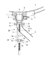
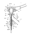
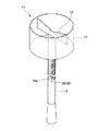
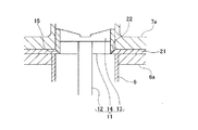
以下、図面を参照し、この発明の実施の形態について説明する。図1から図4はこの発明の一実施の形態に係る振動乾燥装置を示す図であって、図1は振動乾燥装置を示す一部破断の説明図、図2は図1における突き崩し手段を示す拡大断面図、図3は突き崩し手段の突き崩し体を示す拡大斜視図、図4は突き崩し手段の突き崩し体を下限位置まで退避させて規制した状態を示す拡大説明図である。
図1に示すこの実施形態の振動乾燥装置1は、内部が中空とされた容器2と、容器2の下部に設けられた製品排出口3にその製品排出口3を開閉させるバルブ4とが備えられている。そして、容器2内に粉状物が送り込まれたとき、容器2に図示しない駆動源によって振動が付与されることで、粉状物を振動させながら個々に分散させ、また図示しない加熱源によって加熱されることで、粉状物に含まれる水分が蒸発して除去され、粉状物の乾燥が終了した時点で、バルブ4を開くと、容器2内の粉状物が製品排出口3からバルブ4を通過してドレン管6に送り出されるようになっている。
Embodiments of the present invention will be described below with reference to the drawings. 1 to 4 are views showing a vibration drying apparatus according to an embodiment of the present invention. FIG. 1 is a partially broken explanatory view showing the vibration drying apparatus, and FIG. FIG. 3 is an enlarged perspective view showing a break-off body of the break-off means, and FIG. 4 is an enlarged explanatory view showing a state where the break-off body of the break-off means is retracted to a lower limit position and regulated.
The
バルブ4は、ボール状に形成されたいわゆるボールバルブをなしてあって、貫通して形成された連絡孔5を有しており、容器2の製品排出口3に固定されたバルブハウジング7に開閉可能に取り付けられている。このバルブ4は、バルブハウジング7に突出した操作部8が、図示しない操作ハンドルで軸回りに回転されたとき、連絡孔5が製品排出口4とドレン管6を連絡したり遮断したりすることで、開閉する。なお、図1では、連絡孔5が手前背紙方向に沿っていることから遮断され、バルブ4が閉じた状態を表している。
The
そして、この振動乾燥装置1は、容器2内の粉状物が製品排出口3付近に付着してあって製品排出口3を塞いだ場合に備え、図1及び図2に示すように、その製品排出口3に付着している粉状物を突き崩す突き崩し手段10が設けられている。
即ち、突き崩し手段10は、大別すると、粉状物の付着物を突き崩すための突き崩し体11と、この突き崩し体11をバルブ4内に挿通させ、バルブ4の下流部と上流部との間で進退可能に支持する支持装置20とを備えている。
And this
That is, the collapsing
突き崩し体11は、図3に示すように、突き棒12と、その突き棒12の先端に水平に対向して設けられた崩し刃13と、その崩し刃13を中心とする外周に設けられた環状部材14とからなり、崩し刃及び環状部材14がバルブ4の連絡孔5を挿通するようになっている。突き崩し体11の突き棒12は、図1及び図2に示すように、ドレン管6を挿通して外部に引き出されており、ドレン管6との挿通部分には、粉状物が外部に漏れないようシール材(図示せず)が設けられている。
支持装置20は、図2に示すように、突き崩し体11が下降してバルブ4の下流部に後退したとき、この下限位置を規制する規制部材21と、該規制部材21によって突き崩し体11が下限位置にあるとき、突き崩し体を固定させておく固定機構30とを有している。
As shown in FIG. 3, the collapsing
As shown in FIG. 2, the
規制部材21は、図4に示すように、バルブハウジング7の下部フランジ7aとドレン管6の上部フランジ部6a間に挟着された環状板からなっており、その内周部がバルブ4より下方位置の通路内に突設され、突き崩し体11が下降して退避したとき、内周部と当接することで突き崩し体11を下限位置に規制する。その場合、規制部材21の内周部には、上方から下方に至るに従い次第に内方に突出するように形成された傾斜面22が設けられている。
上記傾斜面21は、突き崩し体11の環状部材14の底部に形成された傾斜部15と対応する角度をなしている。
As shown in FIG. 4, the regulating
The
前記固定機構30は、図2及び図3に示すように、突き棒12と軸方向に相対移動可能に螺合する回転体31と、回転体31の下部に軸方向に移動可能に螺着されたソケット部材36と、ソケット部材36に着脱自在に引き掛けられる引き掛け部材してのピン38とからなっている。
回転体31は、突き棒12と螺合すると共に、軸回りに回転自在とされている。即ち、回転体31は、突き棒12を挿通し得る大きさの筒状をなしており、その内側に突き棒12の外周に設けられた雄ネジ12aと螺合する雌ネジ32が設けられ、外周部にハンドル(操作杆)33が突設されている。
また、図2に示すように、回転体31の外周の上部には、リング部材40と係合する係合溝34が設けられ、その係合により、回転体31が軸回りに回転自在に支持されている。リング部材40は容器2及びドレン管6に下方に延在する管41に固定された筒状体42の下端にボルト等によって取り付けられている。さらに、回転体31において、ハンドル33より下方の外周には、雄ネジ35が刻設されている。
As shown in FIGS. 2 and 3, the fixing
The rotating
As shown in FIG. 2, an
ソケット部材36は、軸方向の長さが回転体31より遙かに短い筒状をなしており、その内周に上記雄ネジ35と螺合する雌ネジ37が設けられ、回転することで回転体31上で軸方向に移動できるようにしている。
ピン38は、装置の運転時には、突き棒12において、ソケット部材36より下方の外周に径方向に沿って設けられた貫通孔39に対し挿入されることで引き掛けられ、突き出し体11の使用時には、貫通孔39から抜かれるようになっている。
The
During operation of the apparatus, the
そして、ハンドル33を操作して回転体31を軸回りに回転すると、回転体31と螺合している突き棒12が軸方向に移動することで、つまり、突き崩し体11の崩し刃13及び環状部材14がバルブ4の連絡孔5を通過して上昇したり下降したりするようになっている。また、突き崩し体11が下限位置にあるとき、貫通孔39にピン38を挿通すると共に、そのピン38にソケット部材36が当接するまでソケット部材36を回して下降し、そのソケット部材36がピン38に当接することで、突き崩し体11が下限位置のままで固定されるようになっている。
When the
この実施形態の振動乾燥装置1は、上記のように構成されるので、次に、その動作及び取り扱いについて以下に説明する。
まず、振動乾燥装置1の運転に際しては、係員によって突き崩し手段10の突き崩し体11を容器2に対して固定しておく。
つまり、係員により、図2に示すように、バルブ4が閉じた状態にあって、突き崩し体11の環状部材14が規制部材22に当接するまで下降することで突き崩し体11が下限位置に退避させられる一方、突き棒12の貫通孔39にピン38が挿通されると共に、またソケット部材36が回転して突き棒12に沿って下降され、該ソケット部材36がピン38と係合することで、突き崩し体11を容器2に対して固定した状態としておく。
Since the
First, when the
That is, as shown in FIG. 2, the clerk descends until the
このような状態にあるとき、容器2内に粉状体が送り込まれると、容器2が駆動されて振動しながら加熱されるので、粉状体が振動しつつかつ該粉状体に含まれている水分が除去されることで、粉状体の製品が生成される。そして、粉状体が生成された後、通常では、バルブ4が開かれた時点で、容器2内の粉状体が製品排出口3からバルブ4及び突き崩し体11内の空間を経てドレン管6に自重で排出される。
その際、容器内の粉状体の種類によっては、例えば硝酸カリウム等の種類からなる粉状体が用いられていると、その粉状体が容器2の製品排出口3を塞ぐように固化して付着することがあるので、バルブ4を開いても、粉状体が落下せず、排出されなくなる場合がある。
In such a state, when the powdery body is fed into the container 2, the container 2 is driven and heated while vibrating, so that the powdery body is vibrated and included in the powdery body. By removing the water content, a powdery product is produced. And after a powdery body is produced | generated, when the valve |
At that time, depending on the type of powder in the container, for example, when a powder of a kind such as potassium nitrate is used, the powder is solidified so as to block the
そこで、突き崩し手段10が係員によって操作される。即ち、突き崩し手段10の回転体31において、これと螺合しているソケット部材36を突き棒12上で回して上方にずらし、そのソケット部材36と、突き棒12に挿通しているピン38との係合を解除すると共に、突き棒12の貫通孔39からピン38を抜き取る。
Therefore, the collapsing means 10 is operated by an attendant. That is, in the
次いで、ハンドル33を持って回転体31を軸回りに回転させことで、突き棒12を上方に移動させると、突き棒12の上部に設けられている崩し刃13と環状部材14が、バルブ4の連絡孔5を通過して図2の鎖線にて示すように製品排出口3の上部に向かい、製品排出口3を塞いでいる付着物に突き当たることができるので、その突き当たった衝撃で付着物が破壊され、下方に落下する。
この場合、崩し刃13の回りに環状部材14が設けられていることから、崩し刃13と環状部材14間の空間から付着物の破片及び粉状物が通過するので、粉状物はバルブ4の連絡孔5を通過してドレン管6へ導かれ、外部に排出されることとなる。
Next, when the
In this case, since the
この実施形態によれば、容器2内の粉状物が付着物となって製品排出口3を塞いでも、突き崩し手段10が操作されることで粉状物の付着物を簡単に破砕することができるので、付着物の破片を排出させることができると共に、粉状物の排出を良好に行える。
また、容器2の振動加熱時には、突き崩し手段10の支持装置20により突き崩し体11をバルブ4より下流部に退避させた後、容器2に対する振動加熱を行い、粉状物の水分を蒸発させることができるので、振動乾燥装置1の運転に何等支障をきたすことがない。
しかも、突き崩し体11は、突き棒12と崩し刃13と環状部材14とで構成され、崩し刃13及び環状部材14によって付着物に突き崩したとき、付着物を突き崩すことができ、付着物の破片が環状部材14内を通過するので、付着物を容易に排出させることができ、簡単な構成で付着物の突き崩しと粉状物の排出とを行うことができる。
更に、装置の運転に際し、突き崩し体11が後退して支持装置20の規制部材21によって規制されたとき、固定機構30が突き崩し体11を容器2に対して固定しておくので、容器2の振動時に突き崩し体11がガタツクことがない。
According to this embodiment, even if the powdery substance in the container 2 becomes an adhering matter and plugs the
Further, when the container 2 is vibrated and heated, the collapsing
In addition, the collapsing
Further, when the apparatus is operated, when the collapsing
そして、固定機構30が回転体31とソケット部材36と引き掛け部材としてのピン38とを有して構成され、容器2の振動時、突き崩し体11を確実に固定しておくことができるので、突き崩し体11の固定を簡単な作業で実現できる。
また、振動乾燥装置の運転時、容器2が振動するが、容器2が振動してもそれに拘わることなく、突き崩したい11を固定しておくことができる。即ち、上述したように、回転体31を軸回りに回転させることで、突き崩し体11を下限位置まで降下させ、その下限位置のとき、突き棒12にピン38を挿通すると共に、そのピン38に突き当たるまでソケットを回すと、突き崩し体11がバルブ4の下方位置に固定した状態となるので、容器2の振動に拘わることなく突き崩し体11をガタツクことなく保持しておくことができる。しかも、突き崩し体11がバルブ4の下方位置に固定されるので、バルブ4の開閉動作に支障をきたすということもない。
The fixing
Further, the container 2 vibrates during the operation of the vibration drying apparatus, but even if the container 2 vibrates, it is possible to fix the 11 to be broken without being concerned. That is, as described above, by rotating the
また更に、容器2に対し、突き崩し手段10を追加させることで突き崩し機能を果たすので、元々用いられている容器2の構造を何等変更する必要もなく、従って、従来品の装置にも容易に適用することができ、実用上有益となる。
なお、上記実施の形態において、バルブ4がボールバルブで構成された例を示したが、例えば水平方向にスライドすることで通路を開閉させるタイプのもので構成してもよい。また、突き崩し手段10の具体的構成は図示実施形態に限定されるものではなく、要は、所期の機能が得られればよい。
Furthermore, since the collapsing function is achieved by adding the collapsing means 10 to the container 2, there is no need to change the structure of the container 2 that is originally used, and therefore it is easy to use the conventional apparatus. It is useful for practical use.
In the above embodiment, the
1 振動乾燥装置
2 容器
3 製品排出口
4 バルブ
5 連絡孔
10 突き崩し手段
11 突き崩し体
12 突き棒
13 崩し刃
14 環状部材
20 支持装置
21 規制部材
30 固定機構
31 回転体
36 ソケット部材
38 ピン(引き掛け部材)
DESCRIPTION OF
Claims (5)
前記バルブを開いた時点で、前記容器内の粉状体が排出されない場合、前記容器の製品排出口付近に付着した粉状体の付着物を突き崩す突き崩し手段を備えることを特徴とする振動乾燥装置。 Vibratory drying comprising: a container for drying while vibrating the powdered body; and a valve having a communication hole provided so as to be openable and closable at a product discharge port of the container and allowing the powdery material to pass through the product discharge port when opened. In the device
When the valve is opened, if the powdery substance in the container is not discharged, the vibration is provided with a break-up means for breaking the powdery substance adhering to the vicinity of the product discharge port of the container. Drying equipment.
前記突き崩し手段は、前記バルブの前記連絡孔を挿通して前記付着物を突き崩す突き崩し体と、該突き崩し体を、前記バルブより下流部と上流部との間で進退可能に支持する支持装置とを有することを特徴とする振動乾燥装置。 The vibration drying apparatus according to claim 1,
The collapsing means supports a collapsing body that penetrates the connecting hole of the valve to collide the deposit, and supports the collapsing body between a downstream portion and an upstream portion of the valve. A vibration drying device comprising a support device.
前記突き崩し体は、突き棒と、該突き棒の先端に装着された崩し刃と、該崩し刃を中心とする外周に設けられた環状部材とからなることを特徴とする振動乾燥装置。 The vibration drying apparatus according to claim 2,
The vibration breaker is characterized in that the collapsible body includes a thrust bar, a breaker blade attached to the tip of the thruster, and an annular member provided on the outer periphery centering on the breaker blade.
前記支持装置は、前記突き崩し体が前記バルブの下流部に後退したとき、その下限位置を規制する規制部材と、前記突き崩し体が下限位置にあるとき、前記突き崩し体を前記容器に対して固定しておく固定機構とを有することを特徴とする振動乾燥装置。 The vibration drying apparatus according to claim 2 or 3,
The support device includes: a regulating member that regulates a lower limit position of the collapsing body when the collapsing body is retracted to a downstream portion of the valve; and the collapsing body when the collapsing body is at the lower limit position. And a vibration drying device characterized by having a fixing mechanism for fixing.
前記固定機構は、軸回りに回転自在に支持され、前記突き崩し体を内部に挿通させて該突き崩し体と軸方向に相対移動可能に螺合する回転体と、該回転体の下部に軸方向に移動可能に螺着されたソケット部材と、前記回転体における前記ソケット部材より下部に着脱自在に引き掛けられ、かつ前記突き崩し体が下限位置に規制された位置にあるときに、該ソケット部材と係合される引き掛け部材とを有することを特徴とする振動乾燥装置。
The vibration drying apparatus according to claim 4,
The fixing mechanism is supported rotatably around an axis, and a rotating body that is inserted into the collapsing body and is screwed to the collapsing body so as to be relatively movable in the axial direction. A socket member screwed so as to be movable in a direction, and the socket when detachably hooked below the socket member in the rotating body and the collapsing body is in a position restricted to a lower limit position. A vibration drying device comprising a hook member engaged with the member.
Priority Applications (1)
| Application Number | Priority Date | Filing Date | Title |
|---|---|---|---|
| JP2004113237A JP4313716B2 (en) | 2004-04-07 | 2004-04-07 | Vibration dryer |
Applications Claiming Priority (1)
| Application Number | Priority Date | Filing Date | Title |
|---|---|---|---|
| JP2004113237A JP4313716B2 (en) | 2004-04-07 | 2004-04-07 | Vibration dryer |
Related Child Applications (1)
| Application Number | Title | Priority Date | Filing Date |
|---|---|---|---|
| JP2008250054A Division JP2009002646A (en) | 2008-09-29 | 2008-09-29 | Vibration dryer |
Publications (2)
| Publication Number | Publication Date |
|---|---|
| JP2005299958A true JP2005299958A (en) | 2005-10-27 |
| JP4313716B2 JP4313716B2 (en) | 2009-08-12 |
Family
ID=35331707
Family Applications (1)
| Application Number | Title | Priority Date | Filing Date |
|---|---|---|---|
| JP2004113237A Expired - Lifetime JP4313716B2 (en) | 2004-04-07 | 2004-04-07 | Vibration dryer |
Country Status (1)
| Country | Link |
|---|---|
| JP (1) | JP4313716B2 (en) |
Cited By (2)
| Publication number | Priority date | Publication date | Assignee | Title |
|---|---|---|---|---|
| KR101402615B1 (en) * | 2013-12-09 | 2014-06-02 | 이채원 | The grain vending machine |
| CN113566512A (en) * | 2021-07-10 | 2021-10-29 | 胡应雄 | Viscous material drying device |
-
2004
- 2004-04-07 JP JP2004113237A patent/JP4313716B2/en not_active Expired - Lifetime
Cited By (2)
| Publication number | Priority date | Publication date | Assignee | Title |
|---|---|---|---|---|
| KR101402615B1 (en) * | 2013-12-09 | 2014-06-02 | 이채원 | The grain vending machine |
| CN113566512A (en) * | 2021-07-10 | 2021-10-29 | 胡应雄 | Viscous material drying device |
Also Published As
| Publication number | Publication date |
|---|---|
| JP4313716B2 (en) | 2009-08-12 |
Similar Documents
| Publication | Publication Date | Title |
|---|---|---|
| EP1961458B1 (en) | Fire extinguisher and its use | |
| US6470783B2 (en) | Installation for dismantling chemical bombs | |
| JP4313716B2 (en) | Vibration dryer | |
| JP2009002646A (en) | Vibration dryer | |
| JP2006311820A (en) | Receiving and removing structure of threshing device | |
| HU202597B (en) | Device for injecting media into liquids | |
| US7878100B2 (en) | Method for removing toxic material from toxic weapon projectiles | |
| JP2009074318A (en) | Cleaning method and apparatus for tail seal in shield machine | |
| US5463887A (en) | Device for the preparation of used metal barrels with a view to facilitating handling and recycling thereof | |
| JP2008511443A5 (en) | ||
| US5669435A (en) | Apparatus and method for removing investment material from an investment casting | |
| US1756812A (en) | Method and apparatus for extracting castings from molds | |
| KR100775456B1 (en) | Nozzle inner fixture removal device for mud gun to close the exit line | |
| US6237951B1 (en) | Device for letting pressurized gas stream into a safety device | |
| JP2006320815A (en) | Crushing method and uniaxial crusher using it | |
| JP4155904B2 (en) | Crusher | |
| JP2005335718A (en) | Apparatus for destroying bridge or rat hole of powder and granular material | |
| JP2000117229A (en) | Detoxification equipment for solids containing organic chlorine compounds | |
| JP2007136475A (en) | Soil removal method and mold | |
| KR200209210Y1 (en) | A Remover of Remaining Gas of Liquid Gas Vessel | |
| FR2614826A1 (en) | Method for manufacturing test pieces of molten material and moulds for implementing this method | |
| JP2007119161A (en) | Pin / Chain conveyor | |
| JP5331668B2 (en) | Hammer grab | |
| JP2007074961A (en) | Perforating device for mulch film | |
| KR20120100066A (en) | Apparatus for destroying the solid matter in the restricted working space |
Legal Events
| Date | Code | Title | Description |
|---|---|---|---|
| A621 | Written request for application examination |
Free format text: JAPANESE INTERMEDIATE CODE: A621 Effective date: 20070222 |
|
| A977 | Report on retrieval |
Free format text: JAPANESE INTERMEDIATE CODE: A971007 Effective date: 20080624 |
|
| A131 | Notification of reasons for refusal |
Free format text: JAPANESE INTERMEDIATE CODE: A131 Effective date: 20080729 |
|
| A521 | Request for written amendment filed |
Free format text: JAPANESE INTERMEDIATE CODE: A523 Effective date: 20080929 |
|
| TRDD | Decision of grant or rejection written | ||
| A01 | Written decision to grant a patent or to grant a registration (utility model) |
Free format text: JAPANESE INTERMEDIATE CODE: A01 Effective date: 20090507 |
|
| A01 | Written decision to grant a patent or to grant a registration (utility model) |
Free format text: JAPANESE INTERMEDIATE CODE: A01 |
|
| A61 | First payment of annual fees (during grant procedure) |
Free format text: JAPANESE INTERMEDIATE CODE: A61 Effective date: 20090515 |
|
| FPAY | Renewal fee payment (event date is renewal date of database) |
Free format text: PAYMENT UNTIL: 20120522 Year of fee payment: 3 |
|
| R150 | Certificate of patent or registration of utility model |
Ref document number: 4313716 Country of ref document: JP Free format text: JAPANESE INTERMEDIATE CODE: R150 Free format text: JAPANESE INTERMEDIATE CODE: R150 |
|
| FPAY | Renewal fee payment (event date is renewal date of database) |
Free format text: PAYMENT UNTIL: 20130522 Year of fee payment: 4 |
|
| R250 | Receipt of annual fees |
Free format text: JAPANESE INTERMEDIATE CODE: R250 |
|
| FPAY | Renewal fee payment (event date is renewal date of database) |
Free format text: PAYMENT UNTIL: 20140522 Year of fee payment: 5 |
|
| R250 | Receipt of annual fees |
Free format text: JAPANESE INTERMEDIATE CODE: R250 |
|
| R250 | Receipt of annual fees |
Free format text: JAPANESE INTERMEDIATE CODE: R250 |
|
| R250 | Receipt of annual fees |
Free format text: JAPANESE INTERMEDIATE CODE: R250 |
|
| R250 | Receipt of annual fees |
Free format text: JAPANESE INTERMEDIATE CODE: R250 |
|
| R250 | Receipt of annual fees |
Free format text: JAPANESE INTERMEDIATE CODE: R250 |
|
| R250 | Receipt of annual fees |
Free format text: JAPANESE INTERMEDIATE CODE: R250 |
|
| R250 | Receipt of annual fees |
Free format text: JAPANESE INTERMEDIATE CODE: R250 |
|
| R250 | Receipt of annual fees |
Free format text: JAPANESE INTERMEDIATE CODE: R250 |
|
| R250 | Receipt of annual fees |
Free format text: JAPANESE INTERMEDIATE CODE: R250 |
|
| R250 | Receipt of annual fees |
Free format text: JAPANESE INTERMEDIATE CODE: R250 |
|
| R250 | Receipt of annual fees |
Free format text: JAPANESE INTERMEDIATE CODE: R250 |
|
| EXPY | Cancellation because of completion of term |