JP2005299947A - Shunt device and air conditioner equipped with shunt device - Google Patents
Shunt device and air conditioner equipped with shunt device Download PDFInfo
- Publication number
- JP2005299947A JP2005299947A JP2004112827A JP2004112827A JP2005299947A JP 2005299947 A JP2005299947 A JP 2005299947A JP 2004112827 A JP2004112827 A JP 2004112827A JP 2004112827 A JP2004112827 A JP 2004112827A JP 2005299947 A JP2005299947 A JP 2005299947A
- Authority
- JP
- Japan
- Prior art keywords
- inlet
- refrigerant
- air conditioner
- flow
- heat exchanger
- Prior art date
- Legal status (The legal status is an assumption and is not a legal conclusion. Google has not performed a legal analysis and makes no representation as to the accuracy of the status listed.)
- Withdrawn
Links
Images
Classifications
-
- F—MECHANICAL ENGINEERING; LIGHTING; HEATING; WEAPONS; BLASTING
- F25—REFRIGERATION OR COOLING; COMBINED HEATING AND REFRIGERATION SYSTEMS; HEAT PUMP SYSTEMS; MANUFACTURE OR STORAGE OF ICE; LIQUEFACTION SOLIDIFICATION OF GASES
- F25B—REFRIGERATION MACHINES, PLANTS OR SYSTEMS; COMBINED HEATING AND REFRIGERATION SYSTEMS; HEAT PUMP SYSTEMS
- F25B41/00—Fluid-circulation arrangements
- F25B41/40—Fluid line arrangements
- F25B41/42—Arrangements for diverging or converging flows, e.g. branch lines or junctions
- F25B41/45—Arrangements for diverging or converging flows, e.g. branch lines or junctions for flow control on the upstream side of the diverging point, e.g. with spiral structure for generating turbulence
-
- F—MECHANICAL ENGINEERING; LIGHTING; HEATING; WEAPONS; BLASTING
- F25—REFRIGERATION OR COOLING; COMBINED HEATING AND REFRIGERATION SYSTEMS; HEAT PUMP SYSTEMS; MANUFACTURE OR STORAGE OF ICE; LIQUEFACTION SOLIDIFICATION OF GASES
- F25B—REFRIGERATION MACHINES, PLANTS OR SYSTEMS; COMBINED HEATING AND REFRIGERATION SYSTEMS; HEAT PUMP SYSTEMS
- F25B39/00—Evaporators; Condensers
- F25B39/02—Evaporators
- F25B39/028—Evaporators having distributing means
Landscapes
- Engineering & Computer Science (AREA)
- Physics & Mathematics (AREA)
- Mechanical Engineering (AREA)
- Thermal Sciences (AREA)
- General Engineering & Computer Science (AREA)
- Other Air-Conditioning Systems (AREA)
Abstract
【課題】 室外側熱交換器の暖房サイクル時の入側に設けられるストレーナメッシュと分岐管を一体に構成し、構造及び配管の簡素化によりコストを低減できる分流装置を提供する。
また、上記の分流装置を備えた空気調和機を提供する。
【解決手段】 空気調和機の暖房サイクル時に室外側熱交換器7の入側に接続される分岐管とストレーナメッシュを、上流側に設けた冷媒の入口と、この入口の下流側に設けたストレーナメッシュ13と、ストレーナメッシュ13の下流側に設けられて冷媒の出口を有する分岐管14a,14bとを一体に構成した。
【選択図】 図1
PROBLEM TO BE SOLVED: To provide a flow dividing device in which a strainer mesh and a branch pipe provided on the entrance side of a heating cycle of an outdoor heat exchanger are integrally formed, and the cost can be reduced by simplifying the structure and piping.
Moreover, the air conditioner provided with said diversion apparatus is provided.
A branch pipe connected to an inlet side of an outdoor heat exchanger during a heating cycle of an air conditioner and a strainer mesh are provided at an upstream side of a refrigerant inlet and a strainer provided at a downstream side of the inlet. The mesh 13 and branch pipes 14a and 14b provided on the downstream side of the strainer mesh 13 and having a refrigerant outlet are integrally configured.
[Selection] Figure 1
Description
本発明は、空気調和機に設けられる分流装置及びこの分流装置を備えた空気調和機に関するものである。 The present invention relates to a flow dividing device provided in an air conditioner and an air conditioner including the flow dividing device.
従来の空気調和機を構成する冷媒回路においては、不純物を除去することを目的とするストレーナ又はメッシュと称する網状素子と、蒸発器(室外側熱交換器)入口に設置される分流機構(キャピラリーチューブ)とは、それぞれ独立して構成されていた(例えば、特許文献1参照)。
特許文献1の空気調和機においては、ストレーナと分流機構とはそれぞれ別部品として設置されているため、構造が複雑で配管も面倒であり、コストアップの要因となっていた。 In the air conditioner of Patent Document 1, since the strainer and the flow dividing mechanism are installed as separate parts, the structure is complicated and the piping is troublesome, which causes a cost increase.
本発明は、上記の課題を解決するためになされたもので、室外側熱交換器の暖房サイクル時の入側に設けられる分岐管とストレーナメッシュを一体に構成し、構造及び配管の簡素化によりコストを低減できる分流装置を提供することを目的としたものである。
また、本発明は、上記の分流装置を備えた空気調和機を提供することを目的としたものである。
The present invention has been made in order to solve the above-described problems. The branch pipe and the strainer mesh provided on the inlet side of the outdoor heat exchanger at the time of the heating cycle are integrally configured, and the structure and piping are simplified. An object of the present invention is to provide a diversion device capable of reducing the cost.
Moreover, this invention aims at providing the air conditioner provided with said flow dividing apparatus.
本発明に係る分流装置は、空気調和機の暖房サイクル時に室外側熱交換器の入側に接続される分岐管とストレーナメッシュを、上流側に設けた冷媒の入口と、該入口の下流側に設けたストレーナメッシュと、該ストレーナメッシュの下流側に設けられ前記冷媒の出口を有する分岐管とを一体に構成したものである。 The shunt device according to the present invention includes a branch pipe and a strainer mesh connected to the inlet side of the outdoor heat exchanger during the heating cycle of the air conditioner, and a refrigerant inlet provided on the upstream side and a downstream side of the inlet. The strainer mesh provided and the branch pipe provided on the downstream side of the strainer mesh and having the outlet of the refrigerant are integrally configured.
本発明に係る分流装置によれば、構造及び配管が簡素化されてコストを低減することができ、また、この分流装置により冷媒流が整流されて出口における冷媒流量の分布を均一化できるので、室外側熱交換器内における蒸発部位が偏らず熱交換作用を高効率で行うことができる。
また、上記の分流装置を設置することにより信頼性の高い空気調和機を得ることができ、その上配管作業が簡単で設置費用を低減することができる。
According to the flow dividing device according to the present invention, the structure and piping can be simplified and the cost can be reduced, and the flow of the refrigerant can be rectified by this flow dividing device and the distribution of the refrigerant flow rate at the outlet can be made uniform. The evaporation site in the outdoor heat exchanger is not unevenly distributed and heat exchange can be performed with high efficiency.
In addition, by installing the above-mentioned shunt device, a highly reliable air conditioner can be obtained, and in addition, piping work can be simplified and installation costs can be reduced.
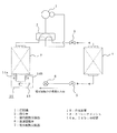
図1は本発明の一実施の形態に係る空気調和機の冷媒回路の説明図である。
図1において、暖房運転時においては、圧縮機1で圧縮された冷媒は、四方弁2、調整弁3を経て凝縮器として作用する室内側熱交換器4へ流入する。室内側熱交換器4によって熱交換された冷媒は調整弁5を介して絞り機構で示した流量調整弁6へ流入する。この流量調整弁6から流出した冷媒は、ストレーナメッシュ13と分岐管14a,14bを一体化した分流装置10を通って複数に分流され、蒸発器として作用する室外側熱交換器7へ流入する。そして、室外側熱交換器7から流出した冷媒は、四方弁2を通過して圧縮機1に吸入され、一巡の冷媒回路を構成する。
FIG. 1 is an explanatory diagram of a refrigerant circuit of an air conditioner according to an embodiment of the present invention.
In FIG. 1, during the heating operation, the refrigerant compressed by the compressor 1 flows into the indoor heat exchanger 4 acting as a condenser through the four-
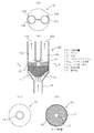
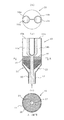
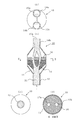
ストレーナメッシュ13と分岐管14a,14bを一体化した分流装置10は、図2に示すように、流量調整弁6側の配管に接続されて冷媒が流入する入口12が形成された小径部、及びそれから拡径された大径部からなるケース11と、多数の細孔を有し入口12の下流側において大径部内に収容されたストレーナメッシュ13と、中心部に絞り孔17を有しストレーナメッシュ13の下流側に配設された絞り機構である仕切り板16と、仕切り板16の下流側に突設され、下端部が仕切り板16の絞り孔17に連通し、上部に配管を介して室外側熱交換器7に連結されて冷媒が流出する出口15a,15bを有する分岐管14a,14bとからなっている。
As shown in FIG. 2, the
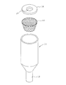
このような分流装置10は、図3に示すように、例えば合成樹脂からなり、下部が小径で上部が拡径されて大径部が形成されて上下が開口されたほぼ円筒状で、壜を逆にしたような形状のケース11内に、多数の細孔を有する網状のストレーナメッシュ13を上部開口部から小径部の近傍まで挿入し、その外周をケース11の内壁に固定する。ついで、ストレーナメッシュ13の上に仕切り板16を挿入してその外周をケース11の内壁に固定する。そして、仕切り板16の上部のケース11を、機械的に塑性加工して2本の分岐管14a,14bを形成したものである。
As shown in FIG. 3, such a
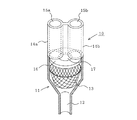
これにより、図4に示すように、下部(小径部)に1個の入口12が形成され、入口12の下流側にストレーナメッシュ13、仕切り板16が順次配設され、仕切り板16の下流側には2本の分岐管14a,14bが形成される。そして、分岐管14a,14bの下端部は仕切り板16の絞り孔17に連通し、上部に出口15a,15bが形成される。
As a result, as shown in FIG. 4, one
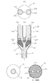
このように構成した分流装置10は、前述のように、その入口12が流量調整弁6側の配管に接続され、出口15a,15bが配管を介して室外側熱交換器7の暖房サイクルにおける前段階(入側)に接続されて設置される。そして、流量調整弁6で減圧されて入口12から流入した冷媒は、図5に示すように、網状のストレーナメッシュ13の細孔を通過する際撹拌されて、配管の横断面内の流速が均一化されることにより整流される。また、冷媒流20に加工工程途上や冷媒回路動作途上で発生した異物等が含まれていれば、ストレーナメッシュ13に絡め取られる。そして、仕切り板16に設けられた絞り孔17によりさらに整流され、2つに分岐した分岐管14a,14bの出口15a,15bから等しい流量分布で流出する。
As described above, the
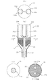
図6の分流装置10は、仕切り板16に、分岐管14a,14bの出口15a,15bの配列と同方向に配列され、それぞれ分岐管14a,14bに連通する2個の絞り孔17a,17bを設けたものである。換言すれば、2個の絞り孔17a,17bは、2個の出口15a,15bと冷媒の流れ方向(矢印で示す)に対する垂直で、相対的に同様の円周位置に設けたものである。
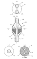
また、図7の分流装置10は、仕切り板16に、分岐管14a,14bの出口15a,15bの配列に対して90°ずれた位置に絞り孔17a,17bを配列したものである。
6 is arranged in the same direction as the
Further, in the
上記のような図6、図7の分流装置10において、模式的に示した冷媒流20が入口12から流入して上方に移動すると、ストレーナメッシュ13を通過する際に撹拌されて整流され、ケース11の横断面の流速が均一化され、また、冷媒流20に含まれた不純物が細孔によって除去される。そして、冷媒流20は仕切り板16の絞り孔17a,17bによってさらに整流され、ケース11の内壁と平行に移動して出口15a,15bに達するので、入口12から仕切り板16に達するまでに円周方向の力を受けることがなく、両分岐管14a,14bの出口15a,15bから等しい流量で流出する。
6 and 7, when the refrigerant flow 20 schematically shown flows from the
この場合、若し、冷媒流20が出口15a,15bに向う過程で偏向しても、ケース11の横断面で円周方向の力を受けて冷媒流20の流れは撹拌されつつ出口15a,15bに達するので、仕切り板16、すなわち絞り機構の通過時及び出口15a,15bにおける両分岐管14a,14b内の冷媒流量は等しくなる。
In this case, even if the
図8の分流装置10は、2個の分岐管14a,14b、したがって出口15a,15bを紙面に対して垂直方向に配列すると共に、仕切り板16にこれと同方向に2個の絞り孔17a,17bを配列したものである。
また、図9の分流装置10は、2個の分岐管14a,14b、したがって出口15a,15bを紙面に対して垂直方向に配列すると共に、仕切り板16にこれから90°ずれた位置に2個の絞り孔17a,17bを配列したものである。
上記のように構成した本実施例においても、実施例1の場合と同様の作用、効果を得ることができる。
8 has two
9 arranges two
Also in the present embodiment configured as described above, the same operations and effects as in the case of the first embodiment can be obtained.
上記の説明では、分流装置10に2個の分岐管14a,14bを設け、仕切り板16に1個の絞り孔17又は分岐管14a,14bの出口15a,15bと同方向若しくは90°ずれた位置に2個の絞り孔17a,17bを設けた場合を示したが、分岐管14は2個以上であってもよい。また、仕切り板16に分岐管14に対応して2個以上の絞り孔17を設けてもよく、その位置も分岐管14に対して意図する冷媒流の分配が得られる任意の角度位置であればよい。
In the above description, the
上記のように構成した本発明に係る分流装置10によれば、ストレーナメッシュ13と分岐管14を一体化したので、構造及び配管を簡素化することができ、コストを低減することができる。
また、この分流装置10を、室外側熱交換器7の暖房サイクルの入側に設置することにより、冷媒流はストレーナメッシュ13の撹拌作用により整流され、分岐管14における冷媒流量の分布を均一化することができるので、室外側熱交換器7内における蒸発部位が偏らず、高効率で熱交換作用を行うことができる。
According to the
Also, by installing this
さらに、本発明に係る分流装置10を室外側熱交換器7の暖房サイクルにおける入側に設置することにより、上記の効果によって信頼性の高い空気調和機を得ることができ、その上配管作業が簡単になるため空気調和機の設置費用を低減することができる。
Furthermore, by installing the
1 圧縮機、2 四方弁、4 室内側熱交換器、6 流量調整弁、7 室外側熱交換器、10 分流装置、12 入口、13 ストレーナメッシュ、14a,14b 分岐管、15a,15b 出口、16 仕切り板、17a,17b 絞り孔。
1 Compressor, 2 Four-way Valve, 4 Indoor Heat Exchanger, 6 Flow Control Valve, 7 Outdoor Heat Exchanger, 10 Flow Divider, 12 Inlet, 13 Strainer Mesh, 14a, 14b Branch Pipe, 15a, 15b Outlet, 16 Partition plate, 17a, 17b Restriction hole.
Claims (5)
The air conditioner characterized by providing the flow diverter in any one of the said Claims 1-4 in the entrance side at the time of the heating cycle of an outdoor side heat exchanger.
Priority Applications (1)
| Application Number | Priority Date | Filing Date | Title |
|---|---|---|---|
| JP2004112827A JP2005299947A (en) | 2004-04-07 | 2004-04-07 | Shunt device and air conditioner equipped with shunt device |
Applications Claiming Priority (1)
| Application Number | Priority Date | Filing Date | Title |
|---|---|---|---|
| JP2004112827A JP2005299947A (en) | 2004-04-07 | 2004-04-07 | Shunt device and air conditioner equipped with shunt device |
Publications (1)
| Publication Number | Publication Date |
|---|---|
| JP2005299947A true JP2005299947A (en) | 2005-10-27 |
Family
ID=35331697
Family Applications (1)
| Application Number | Title | Priority Date | Filing Date |
|---|---|---|---|
| JP2004112827A Withdrawn JP2005299947A (en) | 2004-04-07 | 2004-04-07 | Shunt device and air conditioner equipped with shunt device |
Country Status (1)
| Country | Link |
|---|---|
| JP (1) | JP2005299947A (en) |
Cited By (2)
| Publication number | Priority date | Publication date | Assignee | Title |
|---|---|---|---|---|
| EP2264384A1 (en) * | 2009-06-02 | 2010-12-22 | Johnson Controls Technology Company | A refrigerant distribution device for refrigeration system |
| CN116625034A (en) * | 2023-05-26 | 2023-08-22 | 青岛海尔空调器有限总公司 | Liquid separator, heat exchange system and air conditioner |
-
2004
- 2004-04-07 JP JP2004112827A patent/JP2005299947A/en not_active Withdrawn
Cited By (2)
| Publication number | Priority date | Publication date | Assignee | Title |
|---|---|---|---|---|
| EP2264384A1 (en) * | 2009-06-02 | 2010-12-22 | Johnson Controls Technology Company | A refrigerant distribution device for refrigeration system |
| CN116625034A (en) * | 2023-05-26 | 2023-08-22 | 青岛海尔空调器有限总公司 | Liquid separator, heat exchange system and air conditioner |
Similar Documents
| Publication | Publication Date | Title |
|---|---|---|
| JP6545277B2 (en) | Outdoor unit of air conditioner | |
| EP2596301B1 (en) | Ejector cycle refrigerant separator | |
| JP6104893B2 (en) | Heat exchanger, refrigeration cycle apparatus, air conditioner, and heat exchange method | |
| CN101182965B (en) | Refrigerant distributor and air conditioner with refrigerant distributor | |
| US6735973B2 (en) | Multi-type air conditioner | |
| JP6843256B2 (en) | Refrigerant distributor and air conditioner | |
| WO2007081021A1 (en) | Air conditioner | |
| CN109923348B (en) | Indoor unit of air conditioner and air conditioner | |
| JP2021124226A (en) | Microchannel heat exchanger and air conditioner | |
| JP4560939B2 (en) | Refrigerant shunt and air conditioner using the same | |
| JPH1123104A (en) | Air conditioner | |
| JP2007139231A (en) | Refrigerant distributor and air conditioner using the same | |
| JP2003214727A (en) | Fluid distributor and air conditioner provided with the same | |
| JPH09292166A (en) | Air conditioner | |
| JP2009210225A (en) | Refrigerant divider and heat exchanger comprising the same | |
| JP2007155308A (en) | Shunt and refrigeration cycle apparatus using the same | |
| WO2023058179A1 (en) | Refrigerant distributor, heat exchanger, and air conditioner | |
| JP2006336992A (en) | Air conditioner | |
| JP2009092305A (en) | Refrigerant shunt | |
| JPH11325656A (en) | Header shunt | |
| JP4062011B2 (en) | Two-phase refrigerant flow rectifier and refrigeration system | |
| JP2003314930A (en) | Multi-room air conditioner | |
| KR101424263B1 (en) | Air conditioner | |
| JP2006349238A (en) | Refrigerant shunt | |
| JP6667070B2 (en) | Refrigerant flow divider and refrigeration system using the same |
Legal Events
| Date | Code | Title | Description |
|---|---|---|---|
| A300 | Application deemed to be withdrawn because no request for examination was validly filed |
Free format text: JAPANESE INTERMEDIATE CODE: A300 Effective date: 20070703 |