JP2005299736A - Torque transmission device - Google Patents
Torque transmission device Download PDFInfo
- Publication number
- JP2005299736A JP2005299736A JP2004113612A JP2004113612A JP2005299736A JP 2005299736 A JP2005299736 A JP 2005299736A JP 2004113612 A JP2004113612 A JP 2004113612A JP 2004113612 A JP2004113612 A JP 2004113612A JP 2005299736 A JP2005299736 A JP 2005299736A
- Authority
- JP
- Japan
- Prior art keywords
- clutch
- torque transmission
- coil
- temperature
- electromagnetic
- Prior art date
- Legal status (The legal status is an assumption and is not a legal conclusion. Google has not performed a legal analysis and makes no representation as to the accuracy of the status listed.)
- Pending
Links
Images
Landscapes
- Mechanical Operated Clutches (AREA)
Abstract
【課題】 摩擦クラッチの引きずりトルクを抑制することを可能とする。
【解決手段】 クラッチハウジング79及びシャフト81間をメインクラッチ119を介して断続可能な湿式のパイロットクラッチ121と、パイロットクラッチ121を締結するために通電による電磁力制御を行う電磁コイル147とを備えたトルク伝達カップリング1において、電磁コイル147に隣接して昇温制御用コイル159を備え電磁力制御の停止時に昇温制御用コイル159に高周波パルス電流を供給することで電磁コイル147に高周波交流電流を発生させ、パイロットクラッチ121を昇温制御することを特徴とする。
【選択図】 図3
PROBLEM TO BE SOLVED: To suppress drag torque of a friction clutch.
SOLUTION: A wet pilot clutch 121 that can be connected / disconnected between a clutch housing 79 and a shaft 81 via a main clutch 119, and an electromagnetic coil 147 that performs electromagnetic force control by energization to fasten the pilot clutch 121 are provided. In the torque transmission coupling 1, a temperature increase control coil 159 is provided adjacent to the electromagnetic coil 147, and a high frequency pulse current is supplied to the temperature increase control coil 159 when the electromagnetic force control is stopped, whereby a high frequency alternating current is supplied to the electromagnetic coil 147. And the temperature of the pilot clutch 121 is controlled to increase.
[Selection] Figure 3
Description
本発明は、自動車のトルク伝達装置に関する。 The present invention relates to an automobile torque transmission device.
従来のこの種のトルク伝達装置としては、例えば図7に示すようなものがある。図7は、従来のトルク伝達カップリングの断面図である。図7のように、トルク伝達カップリング201は、カップリングケース203と、中空のシャフト205とが同軸上に配置され、カップリングケース203とシャフト205との間に多板のメインクラッチ207が設けられている。
An example of this type of conventional torque transmission device is shown in FIG. FIG. 7 is a cross-sectional view of a conventional torque transmission coupling. As shown in FIG. 7, in the
前記メインクラッチ207は、押圧プレート209の押圧によって、カップリングケース203に対して締結される。押圧プレート209に対向して、カムプレート211が設けられている。押圧プレート209とカムプレート211との間には、それぞれのカム面間にボール213が介設されている。
The
前記カムプレート211と前記カップリングケース203との間には、多板のパイロットクラッチ215が設けられている。パイロットクラッチ215に対向して、アーマチュア217が設けられている。前記パイロットクラッチ215に対応して、ケーシング218側に電磁コイル219が支持されている。
A
前記カップリングケース203には、植え込みボルト221が設けられている。この植え込みボルト221にフランジ223がナット225によって締結固定されている。フランジ223は、プロペラシャフトに接続される。前記シャフト205には、ドライブピニオンシャフト227が結合される。
The
従って、電磁コイル219への通電による電磁力制御によって、アーマチュア217が移動し、パイロットクラッチ215が締結される。プロペラシャフトからフランジ223に伝達されたトルクは、植え込みボルト221を介してカップリングケース203側に伝達される。このときカップリングケース203と共に回転しようとするカムプレート211が押圧プレート209に対し周方向にずれる。このずれによるカム面とボール213とのカム作用によって押圧プレート209がメインクラッチ207側へ移動し、該メインクラッチ207が締結される。
Therefore, the
前記締結によって、カップリングケース203に入力されたトルクが、メインクラッチ207を介してシャフト205へ伝達される。シャフト205からは、ドライブピニオンシャフト227側へトルク伝達が行われる。
As a result of the fastening, the torque input to the
前記電磁コイル219の電磁力制御が停止されると、パイロットクラッチ215の締結が解除され、カムプレート211が押圧プレート209と共に回転することができ、前記カム作用は働かず、メインクラッチ207の締結が解除される。この場合、パイロットクラッチ215及びメインクラッチ207では、アウタープレート及びインナープレート間で相対回転することができ、基本的にはトルク伝達は行われない。このアウタープレート及びインナープレート間での相対回転時は、カップリングケース203内に封入された潤滑オイルによって潤滑が行われ、焼き付き等の発生を防止することができる。
When the electromagnetic force control of the
しかし、冬季など外気温が低い時には前記潤滑オイルの粘性が高くなり、前記相対回転時にパイロットクラッチ215のアウタープレート及びインナープレート間で制御外の粘性抵抗が働き、粘性によるトルクが発生する。パイロットクラッチ215において粘性によるトルクが発生すると前記押圧プレート209に対してカムプレート211が相対回転し前記カム作用が働く状態となる。このカム作用によりメインクラッチ207が締結され、大きな引きずりトルクが発生するという問題があった。
However, when the outside air temperature is low, such as in winter, the viscosity of the lubricating oil becomes high. During the relative rotation, an uncontrolled viscous resistance acts between the outer plate and the inner plate of the
解決しようとする問題点は、低温時などに粘性により大きな引きずりトルクを招くなど、電磁コイルの断続制御以外の作動が生じること、また電磁コイルの断続制御に対応した作動が得にくい点である。 Problems to be solved are that operations other than the intermittent control of the electromagnetic coil occur, such as inducing a large drag torque due to viscosity at low temperatures, and that it is difficult to obtain an operation corresponding to the intermittent control of the electromagnetic coil.
本発明は、電磁コイルによる断続制御に対応したクラッチの作動を得るため、電磁力制御の停止時に電磁コイルに高周波交流電流を発生させる昇温制御手段を設けたことを最も主要な特徴とする。 The main feature of the present invention is that temperature increase control means for generating a high-frequency alternating current in the electromagnetic coil when the electromagnetic force control is stopped is provided in order to obtain the operation of the clutch corresponding to the intermittent control by the electromagnetic coil.
本発明のトルク伝達装置は、オイルの潤滑環境で使用され、前記電磁コイルの電磁力制御停止時該電磁コイルに高周波交流電流を発生させる昇温制御手段を設けたため、ヒステリシス損或いは電磁誘導作用の少なくとも一方による昇温で潤滑オイルが低温時でもクラッチでの粘性によるトルクの発生など断続制御以外の作動が生じることを抑制することができる。 The torque transmission device of the present invention is used in an oil lubrication environment, and is provided with a temperature rise control means for generating a high-frequency alternating current in the electromagnetic coil when the electromagnetic force control of the electromagnetic coil is stopped. Even when the temperature of the lubricating oil is low, the operation other than the intermittent control such as the generation of torque due to the viscosity of the clutch can be suppressed even when the temperature of the lubricating oil is low.
前記昇温制御手段が、前記電磁コイルに隣接した昇温制御用コイルを備え前記電磁力制御の停止時に前記昇温制御用コイルに高周波パルス電流を供給することで前記電磁コイルに高周波交流電流を発生させる場合は、昇温制御用コイルへの高周波パルス電流の供給により、ヒステリシス損或いは電磁誘導作用の少なくとも一方による確実な昇温を行わせ、低温時でも潤滑オイルの粘性によるクラッチでのトルクの発生など断続制御以外の作動が生じることを抑制することができる。 The temperature increase control means includes a temperature increase control coil adjacent to the electromagnetic coil, and supplies a high frequency pulse current to the temperature increase control coil when the electromagnetic force control is stopped, thereby generating a high frequency alternating current to the electromagnetic coil. In the case of generation, the high temperature pulse current is supplied to the temperature increase control coil so that the temperature is surely increased by at least one of hysteresis loss or electromagnetic induction, and the torque of the clutch due to the viscosity of the lubricating oil is reduced even at low temperatures. Occurrence of operations other than intermittent control such as occurrence can be suppressed.
前記昇温制御手段が、前記電磁力制御の停止時に前記電磁コイルに選択的に接続され高周波パルス電流の通電により前記電磁コイルに流す高周波交流電流を出力する整流回路を備えた場合は、整流回路への高周波パルス電流の通電により、ヒステリシス損或いは電磁誘導作用の少なくとも一方による確実な昇温を行わせ、低温時でもクラッチでの粘性によるトルクの発生など断続制御以外の作動が生じることを抑制することができる。また、整流回路を設けるため、電磁コイル側の変更が無いか、少なくすることができ、設計変更に容易に対応することができる。 When the temperature raising control means includes a rectifier circuit that is selectively connected to the electromagnetic coil when the electromagnetic force control is stopped and outputs a high-frequency alternating current that flows through the electromagnetic coil by energization of a high-frequency pulse current, By energizing a high-frequency pulse current to the coil, it is possible to reliably raise the temperature by at least one of hysteresis loss or electromagnetic induction action, and suppress the occurrence of operations other than intermittent control such as torque generation due to viscosity in the clutch even at low temperatures. be able to. In addition, since the rectifier circuit is provided, there is no or no change on the electromagnetic coil side, and the design change can be easily handled.
前記電磁コイルが、隣接した複数のコイル部分に区分され、前記昇温制御手段が、前記電磁力制御の停止時に前記コイル部分の何れかに高周波パルス電流を供給することで隣接するコイル部分に高周波交流電流を発生させる場合は、確実な昇温を行わせ、低温時でもクラッチでの粘性によるトルクの発生など断続制御以外の作動が生じることを抑制することができながら、電磁コイルを昇温制御用コイルとしても共用することができ、構造を簡単にすることができる。 The electromagnetic coil is divided into a plurality of adjacent coil portions, and the temperature raising control means supplies a high-frequency pulse current to any one of the coil portions when the electromagnetic force control is stopped, whereby a high frequency is applied to the adjacent coil portions. When generating an alternating current, the temperature of the electromagnetic coil is controlled while the temperature is reliably increased, and even when the temperature is low, the occurrence of operations other than intermittent control such as torque generation due to the viscosity of the clutch can be suppressed. It can also be used as an industrial coil, and the structure can be simplified.
前記クラッチが、トルク伝達を断続制御する摩擦クラッチである場合は、潤滑オイルの粘性による摩擦クラッチでのトルク発生など断続制御以外の作動が生じることを確実に抑制することができる。 When the clutch is a friction clutch that intermittently controls torque transmission, it is possible to reliably suppress operations other than intermittent control such as torque generation in the friction clutch due to the viscosity of the lubricating oil.
前記クラッチの温度環境を検出する温度センサを設け、前記昇温制御手段が、前記温度センサが検出するクラッチの温度環境に応じて前記高周波交流電流の発生を制御する場合は、クラッチの温度環境に応じて確実な昇温制御を行うことができる。 When a temperature sensor for detecting the temperature environment of the clutch is provided, and the temperature increase control unit controls the generation of the high-frequency alternating current according to the temperature environment of the clutch detected by the temperature sensor, the temperature environment of the clutch Accordingly, reliable temperature rise control can be performed.
本発明は、電磁力制御の停止時に電磁コイルを用いた断続クラッチ又はその周辺を昇温させるという目的を、簡単な構造で実現した。 The present invention achieves the purpose of raising the temperature of an intermittent clutch using an electromagnetic coil or its periphery when electromagnetic force control is stopped with a simple structure.
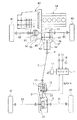
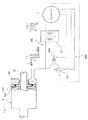
図1は本発明の実施例1を適用するトルク伝達カップリングの配置を示す四輪駆動車のスケルトン平面図である。 FIG. 1 is a skeleton plan view of a four-wheel drive vehicle showing an arrangement of a torque transmission coupling to which a first embodiment of the present invention is applied.
図1のように、トルク伝達装置としてのトルク伝達カップリング1は、横置きフロントエンジンフロントドライブベース(FFベース)の四輪駆動車のリヤデファレンシャル装置3と、プロペラシャフト5との間に設けられている。
As shown in FIG. 1, a
前記トルク伝達カップリング1は、コントローラ7による電磁力制御により締結制御又は昇温制御が行われる。従って、コントローラ7は、本実施例において昇温制御手段をも構成している。なお、昇温制御手段としては、電磁力制御を行うコントローラ7とは別のコントローラにより構成することも可能であり、運転者の意図によるマニュアルのスイッチ断続制御も可能である。
The
前記コントローラ7には、イグニッションスイッチ9,車速センサ11,タイマ13,温度センサ15からの信号が入力されるようになっている。コントローラ7は、イグニッションスイッチ9及び車速センサ11の信号により車両停止時か所定車速以下の走行かを判断し、タイマ13からの信号により後述する高周波交流電流の付与時間や車両放置時間を判断する。また、コントローラ7は、温度センサ11からの信号により後述するクラッチとしての摩擦クラッチの温度環境を判断する。具体的には、温度センサ15からの信号により摩擦クラッチ周辺の空間内の潤滑オイル温度を検出している。なお、温度センサ15からの信号により潤滑剤である潤滑オイルの温度を直接判断する構成、非回転部材の温度、外気温、車両放置時間から潤滑オイルの温度を間接的に判断する構成、前記各種検出信号の組み合わせにより潤滑オイルの温度を判断する構成にすることもできる。コントローラ7は、バッテリ17に接続されている。
Signals from the
前記トルク伝達カップリング1には、前記プロペラシャフト5が等速ジョイント19を介して結合されている。トルク伝達カップリング1の出力側には、ドライブピニオンシャフト21が接続されている。ドライブピニオンシャフト21は、動力伝達ギヤとしてのドライブピニオンギヤ23備えている。ドライブピニオンシャフト21は、デフキャリア25にベアリングを介して回転自在に支持されている。
The
前記リヤデファレンシャル装置3は、前記デフキャリア25に回転自在に支持されている。リヤデファレンシャル装置3のリングギヤ27は、前記ドライブピニオンギヤ23に噛み合っている。リヤデファレンシャル装置3は、左右のアクスルシャフト29,31を介して、左右の後輪33,35に連動連結されている。
The rear differential device 3 is rotatably supported by the differential carrier 25. The
前記プロペラシャフト5は、トランスファ37の出力軸39に等速ジョイント41を介して連動連結されている。出力軸39は、トランスファ37内において、傘歯車43,45、伝動軸47、平歯車49,51を介してフロントデファレンシャル装置53のデフケース55側に連動構成されている。
The
前記フロントデファレンシャル装置53のリングギヤ57には、エンジン59の出力がトランスミッション61を介して入力されるようになっている。前記フロントデファレンシャル装置53は、左右のアクスルシャフト63,65を介して、左右の前輪67,69に連動連結されている。
The output of the
従って、エンジン59の出力トルクは、トランスミッション61からフロントデファレンシャル装置53のリングギヤ57に伝達され、フロントデファレンシャル装置53から左右のアクスルシャフト63,65を介して左右の前輪67,69に伝達される。
Therefore, the output torque of the
また、フロントデファレンシャル装置53のデフケース55から、トランスファ37の平歯車49,51、伝動軸47、傘歯車45,43、出力軸39、等速ジョイント41を介して、プロペラシャフト5へトルク伝達が行われる。
Torque is transmitted from the
前記プロペラシャフト5からは、等速ジョイント19を介してトルク伝達カップリング1にトルク伝達が行われる。
Torque is transmitted from the
前記トルク伝達カップリング1が、トルク伝達可能状態となっていれば、ドライブピニオンシャフト21からドライブピニオンギヤ23を介して、リヤデファレンシャル装置3のリングギヤ27にトルク伝達が行われ、リヤデファレンシャル装置3から左右のアクスルシャフト29,31を介して左右の後輪33,35にトルク伝達が行われる。
If the
従って、トルク伝達カップリング1によってトルク伝達が行われるクラッチ接続状態の場合には、左右の前輪67,69、左右の後輪33,35によって四輪駆動状態で走行することができる。
Therefore, in the clutch connected state where torque transmission is performed by the
前記トルク伝達カップリング1がトルク遮断状態となっているときには、左右の後輪33,35へのトルク伝達は行われず、左右の前輪67,69へのトルク伝達によって二輪駆動状態での走行を行うことができる。
When the
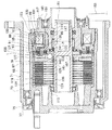
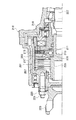
前記トルク伝達カップリング1の具体的構成は図2のようになっている。図2は、トルク伝達カップリング1の取り付け状態を示す断面図である。この図2のように、前記トルク伝達カップリング1は、キャリアカバー71にシールベアリング73を介して回転自在に支持されている。シールベアリング73の外側には、シール75が配置されている。トルク伝達カップリング1の端部には、ダストカバー77が取り付けられ、このダストカバー77と前記キャリアカバー71の端部内周との間に前記シール75が介設されている。
The specific configuration of the
前記トルク伝達カップリング1は、クラッチハウジング79とシャフト81とを備え、後述するシール91,117を介在させることでカップリング1内部には潤滑オイルが封入され、オイル潤滑環境にある。クラッチハウジング79及びシャフト81は回転部材を構成している。
The
前記クラッチハウジング79は、本体部83と端板部85とを備えている。本体部83には、メインクラッチ用及び断続制御を行うクラッチとしてのパイロットクラッチ用のインナースプライン87が設けられ、本体部83の端部内周に雌ねじ部89が形成されている。本体部83には、前記インナースプライン87と雌ねじ部89との間に、Oリング等のシール91が支持され、端板部85外周面に密接している。
The
前記端板部85は、壁部である端板本体部93と、該端板本体部93の背面側内周に形成されたボス部95と、同外周側に形成された外筒部97とが一体に形成されたものである。
The
前記ボス部95及び外筒部97間には、前記端板本体部93の背面側において収容空間部99が設けられている。前記端板本体部93には、前記ボス部95及び外筒部97間において非磁性部101が一体に設けられている。非磁性部101は、端板部85を複合磁性材等により成形することにより一体に形成されている。
An
前記外筒部97の端部外周面には、雄ねじ部103が設けられている。この雄ねじ部103が前記本体部83の雌ねじ部89にねじ込まれて、本体部83に対する端板部85の固定が行われている。前記雄ねじ部103の端部には、ナット105が締結され、本体部83に対する端板部85の緩み止めを行っている。
A
前記シャフト81は、中空に形成され、中間部に隔壁107が設けられている。シャフト81には、隔壁107を挟んで、クラッチハウジング79の本体部83側にスプライン109が設けられている。シャフト81には、隔壁107を挟んで端板部85側には、インナースプライン111が設けられている。シャフト81は、ベアリング113によってクラッチハウジング79の本体部83側に回転自在に支持され、ニードルベアリング115によって端板部85側に回転自在に支持されている。このシャフト81の外周面に、端板部85のボス部95側に支持されたシール117が密接している。
The
前記クラッチハウジング79及びシャフト81間に、メインクラッチ119、パイロットクラッチ121、カムプレート123、押圧プレート125、アーマチュア127が配置されている。
A
前記メインクラッチ119は、複数枚のインナープレート129とアウタープレート131とを備え、両プレート129,131が交互に配置されている。インナープレート129は、前記シャフト81のスプライン109にスプライン係合している。アウタープレート131は、前記クラッチハウジング79の本体部83のインナースプライン87にスプライン係合している。メインクラッチ119は、押圧プレート125の押圧によって締結され、クラッチハウジング79とシャフト81との間のトルク伝達を行う。前記押圧プレート125は、前記シャフト81のスプライン109にスプライン係合している。
The
前記パイロットクラッチ121は、摩擦クラッチで構成され、前記アーマチュア127と、端板部85との間に介在され、複数枚のインナープレート133とアウタープレート135とを備え、両プレート133,135が交互に配置されている。インナープレート133は、前記カムプレート137の外周面のスプライン139にスプライン係合し、アウタープレート135は、前記クラッチハウジング79のインナースプライン87にスプライン係合している。
The
前記メインクラッチ119及びパイロットクラッチ121は、湿式であり、前記クラッチハウジング79とシャフト81との間の閉じ空間内に封入された潤滑オイルによって潤滑環境状態にある。
The
前記アーマチュア127は、前記クラッチハウジング79のインナースプライン87にスプライン係合している。アーマチュア127は、後述する電磁石の磁力によって引き付けられ、パイロットクラッチ121を締結するように端板部85側へ移動する。
The
前記カムプレート137の背面側はニードルベアリング141を介して、前記端板部85側に当接する構成となっている。カムプレート137と押圧プレート125との間には、ボール143を備えたカム機構145が設けられている。
The back side of the cam plate 137 is in contact with the
前記収容空間部65には、電磁石を構成する電磁コイル147が配置されている。電磁コイル147は、クラッチの断続制御として通電による電磁力制御を行うもので、支持体149に固定されている。支持体149は、ベアリング151を介して、前記端板部85のボス部95外周に相対回転自在に支持されている。支持体149は、キャリアカバー71又はデフキャリア25側に回転不能に係合している。電磁コイル147は、前記コントローラ7に対してハーネス153を介し電気的に接続されている。
An
そして、コントローラ7による電磁コイル147への通電によって電磁力制御が行われる。この制御によって、端板部85、支持体1149、アーマチュア127間に磁路155が形成される。磁路131の形成によって、アーマチュア127が端板部85側へ引き付けられ、パイロットクラッチ121が締結される。この締結によって、カムプレート123がクラッチハウジング79側に回転方向に係合する。シャフト81側に係合する押圧プレート125がカムプレート123に対して相対回転し、カム機構145が働いて推力を発生する。この推力は、ニードルベアリング141を介して、端板部85側へ伝達され、その反力として押圧プレート125に作用する。この反力の作用によって、押圧プレート125が移動し、メインクラッチ119が締結される。メインクラッチ119は、締結力に応じてクラッチハウジング79からシャフト81へトルク伝達を行う。
Then, electromagnetic force control is performed by energizing the
従って、前記のように、エンジン59からのトルクを後輪33,35側へメインクラッチ119の締結力に応じて伝達することができる。
Therefore, as described above, torque from the
前記メインクラッチ119及びパイロットクラッチ121の潤滑は、クラッチハウジング79とシャフト81との間の閉じ空間内に充填された潤滑オイルが行う。
The
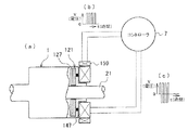
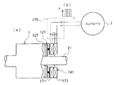
本発明の実施例では、図3(a)のトルク伝達カップリングを含めた回路図のように、前記電磁クラッチ147の外周に昇温制御用コイル159を隣接して配置している。この昇温制御用コイル159は前記コントローラ7に接続されている。
In the embodiment of the present invention, as shown in the circuit diagram including the torque transmission coupling in FIG. 3A, the temperature
前記電磁力制御時は、前記コントローラ7により電磁コイル147に図3(b)で示す波形図の電圧パルスに応じた高周波パルス電流が通電制御される。この通電制御により、上記のようにパイロットクラッチ121が締結制御され、メインクラッチ119が締結される。この締結により車両は四輪駆動状態となっている。
At the time of the electromagnetic force control, the
また、コントローラ7は、前記電磁コイル147による電磁力制御の停止時に前記昇温制御用コイル159に図3(b)で示す波形図の電圧パルスに応じた高周波パルス電流を切り替えて供給し、パイロットクラッチ121の昇温制御を行う。前記電磁力制御の停止時とは、前記コントローラ7による電磁コイル147への通電制御が行われず、車両が二輪駆動状態となっているときである。この状態で、前記パイロットクラッチ121の引きずりトルクがあると、走行抵抗となり燃費向上等に悪影響を及ぼすため、パイロットクラッチ121を昇温制御する。一方、高周波パルス電流が通電制御された状態でも、オイルの粘性によりパイロットクラッチ121の移動時のオイルの粘性抵抗で所定のトルク伝達が行われにくいという理由により電磁制御の停止時にパイロットクラッチ121の昇温制御を行う。
Further, the
但し、本実施例では、二輪駆動時に常時昇温制御をするのではなく、以下のように適時行っている。 However, in this embodiment, the temperature rise control is not always performed during two-wheel drive, but is performed in a timely manner as follows.
前記コントローラ7は、イグニッションスイッチ9及び車速センサ11の信号により車両停止時か所定車速以下の走行かを判断し、前記高周波パルス電流の供給を制御する。この制御により、走行後に潤滑オイルの温度も上昇し、粘性が低くなったにも係わらず不必要に昇温制御を行うと言うことがない。
The
また、コントローラ7は、タイマ13からの信号により車両放置時間を判断して前記高周波パルス電流の供給を制御する。この車両放置時間により潤滑オイルの粘性上昇度合いを判断して的確に昇温制御を行うことができる。
Further, the
さらに、コントローラ7は、タイマ13からの信号により前記高周波交流電流の付与時間を判断して昇温制御を行う。この制御により、パイロットクラッチ121を一定時間以上に不必要に昇温制御することがなく、的確な制御を行うことができる。
Further, the
また、コントローラ7は、温度センサ11からの信号によりパイロットクラッチ121の温度環境を判断し、昇温制御を行う。具体的には、温度センサ15からの信号によりパイロットクラッチ121周辺の空間内あるいはパイロットクラッチ121と近接した部材の温度を判断して制御を行っている。この制御により、パイロットクラッチ121周辺の高低温度環境に応じて的確な制御を行うことができる。
Further, the
前記昇温制御用コイル159に高周波パルス電流が供給されると、電磁コイル147に高周波交流電流が流れる。この高周波交流電流は、例えば図3(c)の波形図で示す電圧波形に応じている。
When a high frequency pulse current is supplied to the temperature
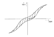
前記電磁コイル147に高周波交流電流が流れると、そのときの磁力Fと電流Iとの関係は、図4のようなヒステリシス特性を示す。この図4の曲線で囲まれた範囲がヒステリシス損となり、エネルギーロスが熱エネルギに変換される。また、電磁コイル147に高周波交流電流が流れるとパイロットクラッチ121が電磁誘導作用によっても発熱する。これらの熱エネルギにより、パイロットクラッチ121が昇温し、外気温が低い場合でもパイロットクラッチ121周辺の潤滑オイルの粘性を低くする、すなわち潤滑オイル自体も昇温することができる。
When a high-frequency alternating current flows through the
前記昇温により粘性が低くなると、パイロットクラッチ121での粘性によるトルク発生が抑制され、カム機構145は働かなくなる。このため、メインクラッチ119は締結力を受けず、外気温が低く走行開始時などにおいても、確実な二輪駆動状態で走行することができる。加えて、通電制御時に伝達トルクを的確に制御するとができる。
When the viscosity decreases due to the temperature increase, torque generation due to the viscosity in the
図5は、本発明の実施例2に係り、(a)はトルク伝達カップリングを含めた回路図、(b),(c)は波形図である。なお、実施例1と対応する構成部分には同符号を付して説明する。 5A and 5B relate to the second embodiment of the present invention, in which FIG. 5A is a circuit diagram including a torque transmission coupling, and FIGS. 5B and 5C are waveform diagrams. In addition, the same code | symbol is attached | subjected and demonstrated to the component corresponding to Example 1. FIG.
図5(a)のように、本実施例では、昇温制御用コイルを特別に設けることなく、整流回路161を設けた。電磁力制御用回路163と昇温制御用回路165とが電磁コイル147に対し並列接続され、電磁力制御用回路163に第1スイッチ167が設けられ、昇温制御用回路165に制流回路161及び第2スイッチ169が設けられている。
As shown in FIG. 5A, in this embodiment, the
電磁力制御の時は第1スイッチ167がON、第2スイッチ169がOFFとされ、昇温制御の時は第1スイッチ167がOFF、第2スイッチ169がONとされる。
During electromagnetic force control, the
電磁力制御の時は、電磁コイル147に(b)で示す高周波パルス電圧に応じた高周波パルス電流が流れる。これにより、前記締結制御が行われる。
At the time of electromagnetic force control, a high frequency pulse current corresponding to the high frequency pulse voltage shown in (b) flows through the
昇温制御の時は、コントローラ7の制御により整流回路161に(b)で示す高周波パルス電圧に応じた高周波パルス電流を通電する。整流回路161に高周波パルス電流が供給されると、(c)の高周波電圧に応じた高周波交流電流が出力される。この高周波交流電流は、電磁コイル147に供給され、実施例1と同様な理由によりパイロットクラッチ121を昇温制御することができる。
At the time of temperature rise control, a high-frequency pulse current corresponding to the high-frequency pulse voltage shown in FIG. When a high frequency pulse current is supplied to the
なお、コントローラ7がイグニッションスイッチ9及び車速センサ11、タイマ13、温度センサ15からの信号に基づいて制御するのは実施例1と同様である。
The
従って、本実施例でも、実施例1と同様にパイロットクラッチ121を昇温制御し、確実な二輪駆動状態で走行することができる。また、本実施例では、整流回路161を設けるため、電磁コイル147側の変更が無いか、少なくすることができ、設計変更に容易に対応することができる。
Therefore, also in the present embodiment, similarly to the first embodiment, the temperature of the
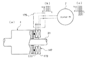
図6,図7は本発明の実施例3に係り、図6(a)はトルク伝達カップリングを含めた電磁制御時の回路図、(b)は波形図、図7(a)はトルク伝達カップリングを含めた昇温制御時の回路図、(b)は波形図である。なお、実施例1と対応する構成部分には同符号を付して説明する。 6 and 7 relate to a third embodiment of the present invention, FIG. 6A is a circuit diagram during electromagnetic control including a torque transmission coupling, FIG. 7B is a waveform diagram, and FIG. 7A is a torque transmission. A circuit diagram at the time of temperature rise control including coupling, (b) is a waveform diagram. In addition, the same code | symbol is attached | subjected and demonstrated to the component corresponding to Example 1. FIG.
本実施例では、電磁コイル147が、隣接した複数、本実施例では二つのコイル部分として第1コイル部分171,第2コイル部分173に区分されている。第1,第2コイル部分171,173は、切替回路175を介してコントローラ7に接続されている。
In this embodiment, the
電磁力制御の時、前記コントローラ7は、図6(a)のように切替回路175を設定して第1,第2コイル部分171,173を直列接続状態とする。この状態で(b)の高周波パルス電圧に応じた高周波パルス電流を電磁コイル147に通電することでパイロットクラッチ121を締結制御し、メインクラッチ119を締結することができる。
At the time of electromagnetic force control, the
昇温制御の時、図7(a)のように切替回路175を切替設定して第1コイル部分171と第2コイル部分173と切り離し、第2コイル部分173をコントローラ7に直列接続させる。この状態で(b)の高周波パルス電圧に応じた高周波パルス電流を第2コイル部分173に通電することで隣接する第1コイル部分171に高周波交流電流を発生させることができる。
At the time of temperature rise control, the
この第1コイル部分171での高周波交流電流の発生により、実施例1と同様な理由によりパイロットクラッチ121を昇温制御することができる。
Due to the generation of the high-frequency alternating current in the
なお、コントローラ7がイグニッションスイッチ9及び車速センサ11、タイマ13、温度センサ15からの信号に基づいて制御するのは実施例1と同様である。
The
従って、本実施例でも、実施例1と同様にパイロットクラッチ121を昇温制御し、確実な二輪駆動状態で走行することができる。また、本実施例では、本来の電磁コイル147を第1,第2コイル部分171,173に分けて切替回路175を設けるだけで良いため、構造が簡単となる。
Therefore, also in the present embodiment, similarly to the first embodiment, the temperature of the
なお、クラッチは、パイロットクラッチに限らず、電磁力により締結制御されるものであれば、ソレノイド式など軸方向に移動するクラッチ部材を有する噛み合いクラッチや磁性流体の粘度に基づき断続制御するもの、また磁力線が透過するロータに対して吸着されるアーマチュアを用いたものなどを例として全て適用することができる。 Note that the clutch is not limited to a pilot clutch, and may be a meshing clutch having a clutch member that moves in the axial direction, such as a solenoid type, or an intermittent control based on the viscosity of a magnetic fluid, as long as the clutch is controlled by electromagnetic force. All the examples using the armature that is attracted to the rotor through which the lines of magnetic force are transmitted can be applied.
前記トルク伝達カップリング1は、リヤデファレンシャル装置3と、プロペラシャフト5との間に配置するものに限らず、例えば、プロペラシャフト5上のトルク伝達カップリング、トランスファ37の出力軸39上のトルク伝達カップリング、又はフロントデファレンシャル装置53と左右前輪67,69との間、すなわちフロントデファレンシャル装置53と左右のアクスルシャフト63,65との間に設けるトルク伝達カップリングとしてそれぞれ設けることもできる。前記プロペラシャフト上に設けるトルク伝達カップリングは、弾性を有するマウント部材によって車体側に取り付けられる。さらには、ハイブリッド車両の内燃機関又は燃料電池などを用いた主駆動系とモータなどの副駆動系との何れかの駆動系に用いられる駆動トルク断続クラッチとしても前記トルク伝達カップリング1を適用可能である。
The
1 トルク伝達カップリング(トルク伝達装置)
3 リヤデファレンシャル装置
5 プロペラシャフト
7 コントローラ(昇温制御手段)
15 温度センサ
33,35 後輪
37 トランスファ
53 フロントデファレンシャル装置
59 エンジン
67,69 前輪
79 クラッチハウジング(回転部材)
81 シャフト(回転部材)
119 メインクラッチ
121 パイロットクラッチ(摩擦クラッチ)
159 昇温制御用コイル(昇温制御手段)
161 整流回路(昇温制御手段)
171 第1コイル部分(コイル部分)
173 第2コイル部分(コイル部分)
1 Torque transmission coupling (torque transmission device)
3 Rear
15
81 Shaft (Rotating member)
119 Main clutch 121 Pilot clutch (friction clutch)
159 Temperature rise control coil (temperature rise control means)
161 Rectifier circuit (temperature increase control means)
171 First coil part (coil part)
173 Second coil part (coil part)
Claims (6)
前記クラッチを締結するために通電による電磁力制御を行う電磁コイルとを備えたトルク伝達装置において、
前記電磁コイルの電磁力制御停止時に該電磁コイルに高周波交流電流を発生させる昇温制御手段を設けたことを特徴とするトルク伝達装置。 A clutch capable of intermittently connecting between rotating members in an oil lubrication environment;
In a torque transmission device including an electromagnetic coil that performs electromagnetic force control by energization to fasten the clutch,
A torque transmission device comprising temperature increase control means for generating a high-frequency alternating current in the electromagnetic coil when electromagnetic force control of the electromagnetic coil is stopped.
前記昇温制御手段は、前記電磁コイルに隣接した昇温制御用コイルを備え前記電磁力制御の停止時に前記昇温制御用コイルに高周波パルス電流を供給することで前記高周波交流電流を発生させることを特徴とするトルク伝達装置。 The torque transmission device according to claim 1,
The temperature increase control means includes a temperature increase control coil adjacent to the electromagnetic coil, and generates the high-frequency alternating current by supplying a high-frequency pulse current to the temperature increase control coil when the electromagnetic force control is stopped. Torque transmission device characterized by.
前記昇温制御手段は、前記電磁力制御の停止時に前記電磁コイルに選択的に接続され高周波パルス電流の通電により前記電磁コイルに流す高周波交流電流を出力する整流回路を備えたことを特徴とするトルク伝達装置。 The torque transmission device according to claim 1,
The temperature increase control means includes a rectifier circuit that is selectively connected to the electromagnetic coil when the electromagnetic force control is stopped and outputs a high-frequency alternating current that flows through the electromagnetic coil by energization of a high-frequency pulse current. Torque transmission device.
前記電磁コイルは、隣接した複数のコイル部分に区分され、
前記昇温制御手段は、前記電磁力制御の停止時に前記コイル部分の何れかに高周波パルス電流を供給することで隣接するコイル部分に高周波交流電流を発生させることを特徴とするトルク伝達装置。 The torque transmission device according to claim 1,
The electromagnetic coil is divided into a plurality of adjacent coil portions,
The temperature raising control means generates a high-frequency alternating current in an adjacent coil portion by supplying a high-frequency pulse current to any one of the coil portions when the electromagnetic force control is stopped.
前記クラッチは、トルク伝達を断続制御する摩擦クラッチであることを特徴とするトルク伝達装置。 The torque transmission device according to any one of claims 1 to 4,
The clutch is a friction clutch that intermittently controls torque transmission.
前記クラッチの温度環境を検出する温度センサを設け、
前記昇温制御手段は、前記温度センサが検出するクラッチの温度環境に応じて前記高周波交流電流の発生を制御することを特徴とするトルク伝達装置。
The torque transmission device according to any one of claims 1 to 5,
A temperature sensor for detecting the temperature environment of the clutch is provided;
The temperature increase control means controls the generation of the high-frequency alternating current according to the temperature environment of the clutch detected by the temperature sensor.
Priority Applications (1)
| Application Number | Priority Date | Filing Date | Title |
|---|---|---|---|
| JP2004113612A JP2005299736A (en) | 2004-04-07 | 2004-04-07 | Torque transmission device |
Applications Claiming Priority (1)
| Application Number | Priority Date | Filing Date | Title |
|---|---|---|---|
| JP2004113612A JP2005299736A (en) | 2004-04-07 | 2004-04-07 | Torque transmission device |
Publications (1)
| Publication Number | Publication Date |
|---|---|
| JP2005299736A true JP2005299736A (en) | 2005-10-27 |
Family
ID=35331517
Family Applications (1)
| Application Number | Title | Priority Date | Filing Date |
|---|---|---|---|
| JP2004113612A Pending JP2005299736A (en) | 2004-04-07 | 2004-04-07 | Torque transmission device |
Country Status (1)
| Country | Link |
|---|---|
| JP (1) | JP2005299736A (en) |
Cited By (6)
| Publication number | Priority date | Publication date | Assignee | Title |
|---|---|---|---|---|
| JP2007177979A (en) * | 2005-12-28 | 2007-07-12 | Gkn ドライブライン トルクテクノロジー株式会社 | Power transmission device |
| JP2007333205A (en) * | 2006-05-15 | 2007-12-27 | Jtekt Corp | Electromagnetic actuator, electromagnetic clutch including the electromagnetic actuator as a constituent mechanism, and vehicle driving force transmission device including the electromagnetic clutch as a constituent mechanism |
| JP2008144936A (en) * | 2006-12-13 | 2008-06-26 | Gkn ドライブライン トルクテクノロジー株式会社 | Power transmission device |
| CN109455089A (en) * | 2017-09-06 | 2019-03-12 | 株式会社捷太格特 | Driving force transmits control device |
| CN109611463A (en) * | 2018-12-27 | 2019-04-12 | 王慧敏 | A method of control electromagnetic clutch |
| CN112840139A (en) * | 2018-10-12 | 2021-05-25 | 埃索欧耐迪克超动力 | Magneto-Rheological Fluid Clutch Device with Low Permeation Drum |
-
2004
- 2004-04-07 JP JP2004113612A patent/JP2005299736A/en active Pending
Cited By (8)
| Publication number | Priority date | Publication date | Assignee | Title |
|---|---|---|---|---|
| JP2007177979A (en) * | 2005-12-28 | 2007-07-12 | Gkn ドライブライン トルクテクノロジー株式会社 | Power transmission device |
| JP2007333205A (en) * | 2006-05-15 | 2007-12-27 | Jtekt Corp | Electromagnetic actuator, electromagnetic clutch including the electromagnetic actuator as a constituent mechanism, and vehicle driving force transmission device including the electromagnetic clutch as a constituent mechanism |
| JP2008144936A (en) * | 2006-12-13 | 2008-06-26 | Gkn ドライブライン トルクテクノロジー株式会社 | Power transmission device |
| CN109455089A (en) * | 2017-09-06 | 2019-03-12 | 株式会社捷太格特 | Driving force transmits control device |
| CN112840139A (en) * | 2018-10-12 | 2021-05-25 | 埃索欧耐迪克超动力 | Magneto-Rheological Fluid Clutch Device with Low Permeation Drum |
| CN112840139B (en) * | 2018-10-12 | 2023-06-06 | 埃索欧耐迪克超动力 | Magneto-rheological fluid clutch device with low-permeation drum |
| CN109611463A (en) * | 2018-12-27 | 2019-04-12 | 王慧敏 | A method of control electromagnetic clutch |
| CN109611463B (en) * | 2018-12-27 | 2020-03-27 | 珠海骏驰科技有限公司 | Method for controlling electromagnetic clutch |
Similar Documents
| Publication | Publication Date | Title |
|---|---|---|
| EP1449704B1 (en) | Torque transfer device having an electric motor/brake actuator and friction clutch | |
| US7211019B2 (en) | Torque vectoring drive mechanism having a power sharing control system | |
| US8597145B2 (en) | Torque transfer unit with integrated electric drive motor | |
| EP2847496B1 (en) | Drive system | |
| CN102089173B (en) | Drivetrains of Motor Vehicles | |
| CN110177956B (en) | Clutch assembly and driving assembly | |
| US7175559B2 (en) | Torque vectoring axle assembly | |
| CN101858425A (en) | The Control of Voltage of locking differential | |
| KR20060042261A (en) | Electro-hydraulic clutch assembly | |
| JP2023010694A (en) | Position-based lubricant control method for disconnect differential | |
| CN113494583A (en) | Differential mechanism and automobile transmission system with same | |
| JP2005299736A (en) | Torque transmission device | |
| CN212297485U (en) | Differential mechanism and automobile transmission system with same | |
| JP4670247B2 (en) | Driving force transmission device | |
| JP2012153247A (en) | Coupling device | |
| JP2015140133A (en) | Vehicle drive system | |
| RU96195U1 (en) | LIQUID CLUTCH FOR DRIVE SHAFT | |
| JP4994212B2 (en) | Driving force distribution transmission device | |
| JP2010006263A (en) | Power transmission device and four-wheel drive vehicle using the same | |
| JP2016215834A (en) | Vehicle control device | |
| JP5314561B2 (en) | Power transmission device | |
| JP2012122538A (en) | Power transmission apparatus | |
| JP2007285459A (en) | Lubrication structure of power transmission device | |
| JP2009264518A (en) | Driving force distribution and transmission device | |
| JP2007205560A (en) | Differential device |