CN112840139B - Magnetorheological fluid clutch apparatus with low permeation drum - Google Patents
Magnetorheological fluid clutch apparatus with low permeation drum Download PDFInfo
- Publication number
- CN112840139B CN112840139B CN201980067302.1A CN201980067302A CN112840139B CN 112840139 B CN112840139 B CN 112840139B CN 201980067302 A CN201980067302 A CN 201980067302A CN 112840139 B CN112840139 B CN 112840139B
- Authority
- CN
- China
- Prior art keywords
- input
- output
- magnetorheological fluid
- clutch apparatus
- fluid clutch
- Prior art date
- Legal status (The legal status is an assumption and is not a legal conclusion. Google has not performed a legal analysis and makes no representation as to the accuracy of the status listed.)
- Active
Links
Images


Classifications
-
- F—MECHANICAL ENGINEERING; LIGHTING; HEATING; WEAPONS; BLASTING
- F16—ENGINEERING ELEMENTS AND UNITS; GENERAL MEASURES FOR PRODUCING AND MAINTAINING EFFECTIVE FUNCTIONING OF MACHINES OR INSTALLATIONS; THERMAL INSULATION IN GENERAL
- F16D—COUPLINGS FOR TRANSMITTING ROTATION; CLUTCHES; BRAKES
- F16D37/00—Clutches in which the drive is transmitted through a medium consisting of small particles, e.g. centrifugally speed-responsive
- F16D37/02—Clutches in which the drive is transmitted through a medium consisting of small particles, e.g. centrifugally speed-responsive the particles being magnetisable
-
- F—MECHANICAL ENGINEERING; LIGHTING; HEATING; WEAPONS; BLASTING
- F16—ENGINEERING ELEMENTS AND UNITS; GENERAL MEASURES FOR PRODUCING AND MAINTAINING EFFECTIVE FUNCTIONING OF MACHINES OR INSTALLATIONS; THERMAL INSULATION IN GENERAL
- F16D—COUPLINGS FOR TRANSMITTING ROTATION; CLUTCHES; BRAKES
- F16D37/00—Clutches in which the drive is transmitted through a medium consisting of small particles, e.g. centrifugally speed-responsive
- F16D2037/004—Clutches in which the drive is transmitted through a medium consisting of small particles, e.g. centrifugally speed-responsive characterised by multiple substantially axial gaps in which the fluid or medium consisting of small particles is arranged
-
- F—MECHANICAL ENGINEERING; LIGHTING; HEATING; WEAPONS; BLASTING
- F16—ENGINEERING ELEMENTS AND UNITS; GENERAL MEASURES FOR PRODUCING AND MAINTAINING EFFECTIVE FUNCTIONING OF MACHINES OR INSTALLATIONS; THERMAL INSULATION IN GENERAL
- F16D—COUPLINGS FOR TRANSMITTING ROTATION; CLUTCHES; BRAKES
- F16D37/00—Clutches in which the drive is transmitted through a medium consisting of small particles, e.g. centrifugally speed-responsive
- F16D2037/007—Clutches in which the drive is transmitted through a medium consisting of small particles, e.g. centrifugally speed-responsive characterised by multiple substantially radial gaps in which the fluid or medium consisting of small particles is arranged
-
- F—MECHANICAL ENGINEERING; LIGHTING; HEATING; WEAPONS; BLASTING
- F16—ENGINEERING ELEMENTS AND UNITS; GENERAL MEASURES FOR PRODUCING AND MAINTAINING EFFECTIVE FUNCTIONING OF MACHINES OR INSTALLATIONS; THERMAL INSULATION IN GENERAL
- F16D—COUPLINGS FOR TRANSMITTING ROTATION; CLUTCHES; BRAKES
- F16D2200/00—Materials; Production methods therefor
- F16D2200/0004—Materials; Production methods therefor metallic
- F16D2200/0026—Non-ferro
- F16D2200/003—Light metals, e.g. aluminium
Abstract
A magnetorheological fluid clutch apparatus includes an input having an input shear surface. The output is rotatably mounted about an input for rotation about an axis common to the input, the output having an output shear surface, the input shear surface and the output shear surface being separated by an annular space. Having a magnetorheological fluid configured to generate a variable amount of torque transmission between the input rotor and the output rotor set when subjected to a magnetic field. The electromagnet transmits a magnetic field through the magnetorheological fluid, the electromagnet configured to change a strength of the magnetic field, whereby actuation of the electromagnet results in torque transmission from the input to the output. The member defining at least one shear surface is made of a low permeability material.
Description
Technical Field
The present disclosure relates generally to Magnetorheological (MR) fluid clutch apparatuses, and more particularly, to configurations of such apparatuses for various applications.
Background
Among other advantages, magnetorheological (MR) fluid clutch apparatuses are used to accurately and precisely transmit motion/force from a drive shaft. Accordingly, more and more applications contemplate the use of MR fluid clutch apparatus. In a typical configuration, the MR fluid clutch apparatus has drums on both the input and output, with the MR fluid being in the annular gap between the shearing surfaces of the drums of the input and output. In order to magnetize the MR fluid in the annular gap, a magnetic field passes through the drum, which is known to use highly permeable materials. For example, steel is commonly used as the material for the drum of MR fluid clutch apparatus.
There are manufacturing limitations associated with steel drums, particularly in terms of thickness associated with cost. Thus, the high penetration drum is relatively thick. The thickness of the drum wall may lead to a non-negligible weight in view of the mass of the steel alloy. As a further consequence, the weight, inertia and momentum of the highly permeable material may affect the bandwidth or natural frequency of the MR fluid clutch apparatus. In some applications requiring high bandwidth, such as in collaborative robots, the robots need to react quickly to human contact to ensure safety, the drum configuration of prior art MR fluid clutch apparatus may hamper its performance.
Disclosure of Invention
It is an object of the present disclosure to provide a Magnetorheological (MR) fluid clutch apparatus that addresses the problems associated with the prior art.
Thus, according to a first embodiment of the present disclosure, there is provided a magnetorheological fluid clutch apparatus comprising: at least one input adapted to be coupled with a torque input, the input having at least one input shear surface; an output rotatably mounted about an input for rotation about a common axis with the input, the output having at least one output shear surface, the input shear surface and the output shear surface being separated by at least one annular space; a magnetorheological fluid in the at least one annular space, the magnetorheological fluid configured to generate a variable amount of torque transmission between the input rotor and the output rotor when subjected to a magnetic field; and at least one electromagnet configured to transfer a magnetic field through the magnetorheological fluid, the electromagnet configured to change a strength of the magnetic field; thus, actuation of the electromagnet results in torque transmission from input to output, wherein at least one member defining at least one shear surface is made of a low permeability material.
Further in accordance with the first embodiment, for example, the at least one output shear surface comprises at least one output drum made of a low permeability material.
Still further, according to the first embodiment, for example, at least the output drum has a thickness ranging from 0.05mm and 1.00mm (including 0.05mm and 1.00 mm).
Still further, according to the first embodiment, for example, a plurality of output drums may be concentrically arranged around a common shaft.
Still further in accordance with the first embodiment, the output drum is defined by a concentric tubular body portion connected to a common radial wall, for example.
Still further in accordance with the first embodiment, the common radial wall is made of a low permeability material, for example.
Still further in accordance with the first embodiment, for example, the concentric tubular body portion and the radial wall are a unitary piece.
Still further, according to the first embodiment, for example, the output drums are cups inserted into each other.
Still further in accordance with the first embodiment, for example, at least one of the output drums is cylindrical.
Still further in accordance with the first embodiment, for example, the at least one input shear surface comprises at least one input drum made of a low permeability material.
Still further, according to the first embodiment, for example, at least the input drum has a thickness ranging from 0.05mm and 1.00mm (including 0.05mm and 1.00 mm).
Still further, according to the first embodiment, for example, a plurality of input drums may be arranged concentrically around a common shaft.
Still further in accordance with the first embodiment, the input drum is defined by a concentric tubular body portion connected to a common radial wall, for example.
Still further in accordance with the first embodiment, the common radial wall is made of a low permeability material, for example.
Still further in accordance with the first embodiment, for example, the concentric tubular body portion and the radial wall are a unitary piece.
Still further, according to the first embodiment, for example, the input drums are cups inserted into each other.
Still further in accordance with the first embodiment, for example, the annular space between the input shear surface and the output shear surface has a width of 0.25mm +/-0.05 mm.
Still further in accordance with the first embodiment, the low permeability material is, for example, plastic or aluminum.
Still further, according to the first embodiment, for example, plastic or aluminum is doped with metal particles.
Still further in accordance with the first embodiment, the low permeability material has, for example, at most 1.0X10 -4 Permeation of H/m.
Still further in accordance with the first embodiment, the input is rotatable, for example.
Still further in accordance with the first embodiment, for example, the input is static and the torque input is braking torque.
According to a second embodiment of the present disclosure, there is provided a magnetorheological fluid clutch apparatus including: at least one input adapted to be coupled with a torque input, the input having at least one input shear surface; an output rotatably mounted about an input for rotation about a common axis with the input, the output having at least one output shear surface, the input shear surface and the output shear surface being separated by at least one annular space; a magnetorheological fluid in the at least one annular space, the magnetorheological fluid configured to generate a variable amount of torque transmission between the input rotor and the output rotor when subjected to a magnetic field; and at least one electromagnet configured to transfer a magnetic field through the magnetorheological fluid, the electromagnet configured to change a strength of the magnetic field; thus, actuation of the electromagnet results in torque transmission from input to output, wherein at least one member defining at least one shear surface is made of plastic or aluminum.
Drawings
FIG. 1 is an exemplary schematic illustration of a Magnetorheological (MR) fluid clutch apparatus according to the disclosure;
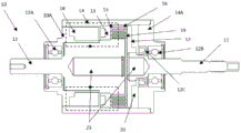
FIG. 2 is a schematic cross-sectional view of the MR fluid clutch apparatus of FIG. 1 in accordance with one embodiment;
FIG. 3 is a schematic cross-sectional view of the MR fluid clutch apparatus of FIG. 1 in accordance with another embodiment;
FIG. 4 is a schematic cross-sectional view of the MR fluid clutch apparatus of FIG. 1 in accordance with yet another embodiment;
FIG. 5 is a schematic cross-sectional view of an MR fluid brake apparatus according to yet another embodiment;
FIG. 6 is a close-up view of a pull cup (drawn cup) arrangement of the MR fluid clutch apparatus of FIG. 4; and
fig. 7 is a schematic cross-sectional view of an MR fluid brake apparatus using a disc instead of a drum.
Detailed Description
Referring to the drawings and more particularly to FIG. 1, a Magnetorheological (MR) fluid clutch apparatus 10 configured to provide a mechanical output force based on a received input current is illustrated. As an illustrative example, MR fluid clutch apparatus 10 is shown of the type having input and output shafts 12 and 11, respectively, collinear, with the axis of rotation shown as CL. The concepts described herein may be applied to other configurations of the MR fluid clutch apparatus 10, such as, for example, some having input or output housings/housings for the output or input shafts, others having input and output housings, etc. The principles illustrated herein will be explained with reference to an MR fluid clutch apparatus having a drum, but may also be applied to a plate type MR fluid clutch apparatus, i.e. an MR fluid clutch apparatus having a disc with a radial surface being the primary shear surface for torque transmission. Such an MR fluid clutch apparatus is shown in FIG. 7.
The MR fluid clutch apparatus 10 can provide an output force in response to an input current received from a controller to transmit the input force. According to one embodiment, the exemplary MR fluid clutch apparatus 10 of FIGS. 1 and 2 may have a stator 10A by which the MR fluid clutch apparatus 10 is connected to a structure. The fixed stator 10A may allow the MR fluid clutch apparatus 10 to provide a multi-turn output (i.e., the output may be rotated greater than 360 degrees relative to the axis X). In some applications, where multiple turns are not required, the stator may not be present in the MR fluid clutch apparatus 10. The MR fluid clutch apparatus 10 is characterized by a driven member 11 (shown via its shaft 11) and a driving member 12 (also shown via its shaft 12) separated by a gap filled with MR fluid, as described below. The drive member 12 may receive rotational energy (torque) from a power device (e.g., a motor or similar torque source) with or without a rotating device (e.g., a reduction gearbox, a conveyor belt, etc.).
According to one embodiment, the driving member 12 may be in mechanical communication with a power input, and the driven member 11 may be in mechanical communication with a power output (i.e., force output, torque output). As shown in fig. 2 to 4, the stator 10A, the driven member 11, and the driving member 12 may be connected to each other by bearings 12A and 12B. Two bearings are shown, but there may be more bearings. Further, as described above, the MR fluid clutch apparatus 10 may not have a stator, the driven member 11 and the driving member 12 are directly rotatably connected to each other, and one or both of them is mounted to a structure or the like. In the illustrated embodiment, the bearing 12A is located between the stator 10A and the drive member 12, while the bearing 12B is located between the driven member 11 and the drive member 12. A seal 12C, such as a cup seal (O-ring, etc. shown) may also be provided at the interface between the driven member 11 and the driving member 12 and/or stator 10A to retain MR fluid between the members 11 and 12. In addition, seals are provided to prevent MR fluid from reaching the bearing 12B or leaking out of the device 10.
As shown below with reference to fig. 2 to 4, the drum is located on the circumference around the rotation axis CL. The drum may be defined as having a tubular body portion about a rotational axis CL. The tubular body portion of the drum is shown as cylindrical, but may have other shapes, such as conical. Thus, some of the support members must extend generally radially to support the tubular body portion of the drum in its circumferential arrangement. According to one embodiment, referring to fig. 2, a low-permeability input drum support 13 (also referred to as a radial wall or disc/disk) protrudes radially from the shaft of the drive member 12. The input drum support 13 may be connected to an input rotor 14 defining an outer housing or shell of the MR fluid clutch device 10. Accordingly, the input rotor 14 may be rotatably connected with the driven member 11 through the bearing 12B. In one embodiment, the input rotor 14 has an input rotor support 14A, the input rotor support 14A forming a housing for the bearing 12B. According to one embodiment, the input rotor support 14A is an integral part of the input rotor 14 and may be manufactured as a single piece. However, this is not necessary, as the input rotor support 14A may be made of a low permeability material and the input rotor 14 may be made of a high permeability material as a possibility, among other things. As another example, as shown in fig. 2, the input rotor support 14A may be defined by an annular wall manufactured separately from the remainder of the input rotor 14, although the two are connected to each other in any suitable manner for simultaneous rotation. Thus, in the illustrated embodiment, the shaft of the drive member 12, the input drum support 13 and the input rotor 14 rotate simultaneously. In one embodiment, it is contemplated that the housing of the MR fluid clutch apparatus 10 is part of the stator 10A or driven member 11.
The input drum support 13 may support one or more concentric annular drums 15, also known as input annular drums. The input annular drum 15 is fixed to an input drum support 13 common to the annular drum 15. In one embodiment, concentric annular channels are defined (e.g., machined, cast, molded, etc.) in input drum support 13 to insert drum 15 therein. Tight fitting (e.g., force fitting), adhesive, and/or radial pins are one of many solutions that may be used to secure the drum 15 to the input drum support 13. In one embodiment, the input drum support 13 is fixed to a shaft (e.g., unitary structure, welded, splined, etc.) of the drive member 12, whereby the various components of the drive member 12 rotate simultaneously when receiving drive from the power source.
The driven member 11 is represented by an output shaft, which is also configured to rotate about the axis CL. When the MR fluid clutch apparatus 10 is actuated to transmit at least some of the rotational power input from the drive member 12, the output shaft may be coupled to various mechanical components (which receive the transmitted power output).
The driven member 11 also has one or more concentric annular drums 16, also known as output drums, mounted to an output drum support 17. The output drum support 17 may be an integral part of the output shaft or may be mounted to the output shaft for simultaneous rotation. The annular drums 16 are spaced apart in such a way that a set of output annular drums 16 fits in an interleaved manner within the annular space between the input annular drums 15. When either one of the driven member 11 and the driving member 12 rotates about the axis CL, there may be no direct contact between the annular drums 15 and 16 due to concentricity of the annular drums 15 and 16.
In the embodiment of fig. 2, the input drum 15 may consist of a heavy, high-permeability material (e.g. steel) or a light, low-permeability material (e.g. plastic, plastic doped with metal particles or aluminum) -where the infiltration is magnetic, e.g. in terms of H/m or N/a 2 . The low permeability can be defined as 1.0X10 -4 H/m or less, i.e. up to 1.0X10 -4 H/m. The output drum 16 may be made of a low permeability material (e.g., plastic doped with metal particles or aluminum). The plastic may be a polymer that is capable of withstanding the relatively high operating temperatures of the MR fluid as it rubs. Examples of polymers that may be used include, for example, polyetheretherketone (PEEK) or polyamide. Drums 15 and/or 16 employing low permeability materials may be relatively thin, ranging in thickness from 0.05mm and 1.00mm (including 0.05mm and 1.00 mm).
According to one embodiment, the annular space has a width of 0.25mm +/-0.05mm between the facing surfaces of the set of drums 15 and 16, i.e. in the radial direction. These surfaces may be known as shear surfaces. The width range of the annular space is provided as a non-exclusive example only, as other annular space widths are also contemplated, as are various factors such as total torque, component size, viscous drag, etc.
In embodiments having a stator 10A, the electromagnet unit 18 may be supported by the stator 10A. The electromagnet unit 18 is used to activate and control the clutch function of the MR fluid clutch apparatus 10. The electromagnet unit 18 is shown schematically but may conventionally have a toroidal coil and core forming an electromagnet and/or a permanent magnet, as well as all necessary wiring for manufacturing the variable magnetic field.
The annular space between the annular drum 15 of the driving member 12 and the annular drum 16 of the driven member 11 is filled with MR fluid 19. The MR fluid 19 for transmitting forces between the driven member 11 and the driving member 12 is of the smart fluid type, which consists of magnetizable particles arranged in a carrier fluid, typically an oil. When subjected to a magnetic field, the liquid may increase its apparent viscosity, possibly reaching a point where it becomes a viscoplastic solid. The apparent viscosity is defined by the ratio between the operational shear stress and the operational shear rate of the MR fluid comprised between the opposing shear surfaces. The magnetic field strength mainly affects the yield shear stress of the MR fluid. By varying the strength of the magnetic field generated by the electromagnet and/or the permanent magnet, i.e. the input current, via the use of a controller, the yield shear stress of the liquid in the activated ("on") state can be controlled. Thus, the ability of the MR fluid to transfer force can be controlled by the electromagnet unit 18, thereby acting as a clutch between the members 11 and 12. The electromagnet unit 18 is configured to vary the magnetic field strength via the controller such that the friction between the members 11 and 12 is sufficiently small to allow the driving member 11 to freely rotate relative to the driven member 12 and vice versa. Thus, by varying the magnetic flux to which the MR fluid is exposed, the MR fluid clutch apparatus 10 can vary the amount of force provided in response to the received input. Specifically, the MR fluid clutch apparatus 10 can provide an output force based on an input force by varying the magnetic flux based on the input force.
The annular space between each set of drums 15 and 16 is part of an MR fluid chamber sealed by one or more seals. The MR fluid chamber comprises an annular space between a set of drums 15 and 16, and may include the space at the tips of the drums, as well as the space between the drums 15 and 16 and the shear surface, which is part of the shaft of the input rotor 14 and drive member 12. The MR fluid chamber may also include an annular space 20 located opposite the output drum support 17. According to one embodiment, the flow of MR fluid is as follows. When the drive member 12 rotates, the input drum 15 may produce some pumping action by which the MR fluid 19 moves in a radially outward direction after reaching the ends of the drums 15 and 16. When the outermost drum 16 is exceeded, the MR fluid 19 may be directed past the radial edge of the output drum support 17 and into the annular space 20. The MR fluid 19 will move radially inward to return to the other side of the output drum support 17 to circulate between the drums 15 and 16 via the holes in the output drum support 17.
Movement of the MR fluid in the manner described above allows the MR fluid to circulate in the MR fluid chamber. The movement can be achieved via the presence of a spiral channel on the surface of the drum 15. Other localized variations of penetration or surface depressions may also be used for either of the drum sets 15 or 16 to induce pumping action in the MR fluid chamber, i.e., some form of cavities, protrusions or channels in other smooth cylindrical surfaces.
In the embodiment of fig. 3, the MR fluid clutch apparatus 10 is similar to the apparatus of fig. 2, and like reference numerals refer to like elements. In the embodiment of fig. 3, the input drum support 13 and the input drum 15 are one integral piece, such as a unitary piece, as shown by assembly 21. The output drum 16 and the output drum support 17 may also be made of one integrated piece, such as a single piece, as shown in assembly 22. For example, the assembly 21 of the input drum support 13 and the input drum 15 may be composed of a relatively heavy high permeability material (e.g., steel) or a light low permeability material (e.g., plastic doped with metal particles or aluminum). The assembly 22 is made of a low permeability material (e.g., plastic doped with metal particles, aluminum or aluminum doped with metal particles, etc.). According to one embodiment, assembly 21 and/or assembly 22 are integrally molded as a single piece. For example, the components 21 and/or 22 may be injection molded from plastic.
In the embodiment of fig. 4, the MR fluid clutch apparatus 10 is similar to the apparatus of fig. 2, and like reference numerals refer to like elements. In fig. 4, the input drum 15 and/or the output drum 16 are imprinted in a light, low-permeability material (e.g. plastic, plastic doped with metal particles, aluminum or aluminum doped with metal particles, among other possibilities). In the embodiment of fig. 4, the input drum 15 and/or the output drum 16 may be considered as a plurality of cylindrical cups inserted into each other from large to small. This is shown in more detail in fig. 6, for example, where the annular line is removed to emphasize the cup. Such a line is presented in fig. 4 in the form of a vertical line at the open end of the cup.
Fig. 6 is a close-up view of the input drum 15 and/or output drum 16 of the MR fluid clutch apparatus 10 of fig. 4. The close-up shows a plurality of cylindrical cups inserted into each other from large to small. The cups may be attached to each other by any suitable means, including spot welding, adhesive, press fitting, or any other type of mechanical connection method.
In one or more embodiments of fig. 2-4, the space 20 (if present) may be in fluid communication with an expansion system 23. The inflation system 23 may be located in a cavity within the shaft of the driven member 11 and the driving member 12 and the cavity may be filled with a compliant material, such as closed cell neoprene, or a diaphragm or similar compliant membrane. This is an example of, among other things, MR fluid circulation.
In one or more of the embodiments of fig. 2-4, when an electric current is passed through the toroidal coil, a magnetic field is generated in the core of the electromagnet unit 18 and through the interleaved arrangement of the drums 15 and 16 and the shearing surfaces of the shaft 12 and input rotor 14, the MR fluid 19 is located therebetween. Thus, the magnetic field increases the apparent viscosity of the MR fluid 19 to seize the drums 15 and 16, thereby causing transmission of rotational motion from the input drum 15 to the output drum 16. The interleaved arrangement of drums 15 and 16 allows for an increase in the overall clutch interface and clutch interface per volume of MR fluid 19. In another embodiment, the electromagnet unit 18 is used to reduce the magnetic field on the arrangement of drums 15 and 16 caused by the permanent magnets. This is described, for example, in PCT patent application publication WO 2016/168834, entitled "Magnetorheological Fluid Clutch Apparatus with Cylindrical Air Gap" which is incorporated herein by reference.
In one possible configuration, a power source (not shown) causes the drive member 12 to rotate during operation. The MR fluid 19 transfers at least some of the rotational energy (torque) to the driven member 11 by the magnetic field applied by the electromagnet unit 18, thereby causing the driven member 11 to rotate. The electromagnet unit 18 subjects the MR fluid 19 to a magnetic field that, if changed, can change the apparent viscosity of the MR fluid 19. Next, changing the apparent viscosity of the MR fluid 19 may change the amount of rotational energy transmitted from the driving member 12 to the driven member 11. Thus, in the example of the MR fluid clutch apparatus 10, the amount of rotational energy transferred to the driven member 11 can be adjusted by controlling the amount of magnetic field generated by the electromagnet unit 18 (e.g., via a controller).
The use of low permeability material for the drums 15 and/or 16 may result in a lighter MR fluid clutch device 10 than a high permeability drum 15 and/or 16 of the same diameter. In some cases, the inertia of the output drum 16 may be reduced by more than four times by using a light, low permeability material (i.e., plastic). In a specific arrangement, it may have the effect of doubling the bandwidth of the MR fluid clutch apparatus 10. Accordingly, the performance of the MR fluid clutch apparatus 10 of the present disclosure can be improved in bandwidth (i.e., response frequency) via reducing the inertia of the MR fluid clutch apparatus 10 without the need for low permeability materials for the drum or disk. Furthermore, due to the lower inertial and momentum forces resulting from the reduced weight in drums 15 and/or 16, the durability of MR fluid 19 may be increased, as this may result in reduced slippage. It may also be advantageous to "stick" or adhere the boundary layer of MR fluid 19 to the drum surface (e.g., increase torque, increase MRF durability, and reduce drum wear). Increasing the adhesion may limit the slip between the liquid boundary layer and the adjacent drum surface. Having limited slip may distribute the shearing motion among the MR fluid 19 itself, between the MR fluid particles, rather than between the drum surface and the MR fluid particles. The boundary layer velocity associated with drum 15/16 may also decrease. The surface of the drum 15/16 may be irregular or have a high roughness due to the degree of freedom of manufacturing, and this may be used to increase the adhesion of the MR fluid 19 on the drum surface. The surface of the low permeability material may also be coated with a thin film of high permeability material to increase the tendency of the MR fluid 19 to adhere to the drum material.
The MR fluid clutch apparatus 10 of the present disclosure may have an increased torque-to-inertia ratio resulting from a lighter drum, as compared to an MR fluid clutch apparatus having a drum made of only a highly permeable material. Higher torque-to-inertia ratios may improve controllability (higher bandwidth). However, the use of a low permeability material for the drum will reduce the ability of the drum to support and transmit magnetic flux, and thus, the magnetic flux in the MR fluid 19 can be reduced for a given design and coil current. If the magnetic circuit of the MR fluid clutch apparatus 10 reaches saturation, this may result in a decrease in the torque-to-weight ratio of the MR fluid clutch apparatus 10. The torque to weight ratio can be kept high, especially by keeping the thickness of the low permeability material relatively low. Because a larger coil for the electromagnet unit 18 may be required to saturate the MR fluid 19, the torque to volume ratio of the MR fluid clutch device 10 may also be reduced as compared to conventional MR fluid clutch devices. This ratio can also be controlled by keeping the thickness of the low permeability material as small as possible.
As shown in the embodiments of fig. 2-4, by making some or all of the drums 15 and/or 16 from a low permeability material, portions may be combined together, such as the input drum support 13 with the input drum 15 and/or the output drum support 17 with the output drum 16. Combining the parts may reduce the number and cost of the parts.
In the embodiment of fig. 5, the MR fluid brake apparatus 50 is similar to the MR fluid clutch apparatus 10 of fig. 2, wherein like reference numerals refer to like elements. The MR fluid brake apparatus 50 may also be referred to as an MR fluid clutch apparatus having a stationary member. In fig. 5, the drive member 12 and stator 10A are now shown as non-moving parts, such that the stator 10A acts as a brake when mounted on a chassis (not shown) or similar structure. In other words, in fig. 5 there is no stator 10A or no drive member 12. The torque generation of the MR fluid brake device 50 is similar to that of the MR fluid clutch apparatus 10 of fig. 1 to 4, and the driven member 11 rotates due to its output that can be received via its shaft, and rotates from outside the MR fluid clutch apparatus 50. By means of the static driving member 12/stator 10A, the electromagnet unit 18 is braked to cause a braking effect on the driven member 11. The MR fluid brake apparatus 50 may have a cup-shaped configuration as shown in Figs. 4 and 6, or a configuration as shown in Figs. 2 and 3.
Fig. 7 is an MR fluid brake apparatus 70 which is similar to the MR fluid brake apparatus 50 of fig. 5, but differs in that it uses discs 71 and 72 instead of drums. Similar configurations of discs 71 and 72 may exist with discs 71 and/or 72 in the embodiments of fig. 2-4. Discs 71 and/or 72 may be made of a low permeability material. In one embodiment, the support (whether shaft or housing) for discs 71 and/or 72 is stiffer than discs 71 and 72.
Claims (23)
1. A magnetorheological fluid clutch apparatus, comprising:
at least one input adapted to be coupled to a torque input, the input having at least one input shear surface;
an output rotatably mounted about the input for rotation about an axis common to the input, the output having at least one output shear surface, the input shear surface and the output shear surface being separated by at least one annular space;
a magnetorheological fluid in the at least one annular space, the magnetorheological fluid configured to generate a variable amount of torque transmission between the at least one input and the output when subjected to a magnetic field; and
at least one electromagnet configured to transfer a magnetic field through the magnetorheological fluid, the electromagnet configured to change a strength of the magnetic field;
whereby actuation of said electromagnet results in a torque transmission from said input to said output,
wherein the at least one output shear surface is made of a low permeability material such that a return path of the magnetic field passes through the low permeability material.
2. The magnetorheological fluid clutch apparatus according to claim 1, wherein the output comprises at least one output drum made of a low permeability material, the at least one output drum defining the at least one output shear surface.
3. The magnetorheological fluid clutch apparatus according to claim 2, wherein the at least one output drum has a thickness in the range of 0.05mm to 1.00mm inclusive.
4. A magnetorheological fluid clutch apparatus according to any one of claims 2 and 3, comprising a plurality of said output drums arranged concentrically about said common axis.
5. The magnetorheological fluid clutch apparatus according to claim 4, wherein the output drum is defined by a concentric tubular body portion connected to a common radial wall.
6. The magnetorheological fluid clutch apparatus according to claim 5, wherein the common radial wall is made of a low permeability material.
7. The magnetorheological fluid clutch apparatus according to claim 5, wherein the concentric tubular body portion and the common radial wall are a unitary piece.
8. The magnetorheological fluid clutch apparatus according to claim 5, wherein the output drums are cups interposed with each other.
9. The magnetorheological fluid clutch apparatus according to any one of claims 2 to 8, wherein the at least one output drum is cylindrical.
10. The magnetorheological fluid clutch apparatus according to any one of claims 1 to 9, wherein the at least one input comprises at least one input drum made of a low permeability material, the at least one input drum defining the at least one input shear surface.
11. The magnetorheological fluid clutch apparatus according to claim 10, wherein the at least one input drum has a thickness in the range of 0.05mm to 1.00mm inclusive.
12. The magnetorheological fluid clutch apparatus according to any one of claims 10 and 11, comprising a plurality of the input drums concentrically arranged about the common shaft.
13. The magnetorheological fluid clutch apparatus according to claim 12, wherein the input drum is defined by a concentric tubular body portion connected to a common radial wall.
14. The magnetorheological fluid clutch apparatus according to claim 13, wherein the common radial wall is made of a low permeability material.
15. The magnetorheological fluid clutch apparatus according to claim 13, wherein the concentric tubular body portion and the common radial wall are a unitary piece.
16. The magnetorheological fluid clutch apparatus according to claim 5, wherein the input drums are cups interposed with each other.
17. The magnetorheological fluid clutch apparatus according to any one of claims 1 to 16, wherein the annular space between the input shear surface and the output shear surface has a width of 0.25mm +/-0.05 mm.
18. The magnetorheological fluid clutch apparatus according to any one of claims 1 to 17, wherein the low permeability material is plastic or aluminum.
19. The magnetorheological fluid clutch apparatus according to claim 18, wherein the plastic or aluminum is doped with metal particles.
20. The magnetorheological fluid clutch apparatus according to any one of claims 1 to 19, wherein the low permeability material has at most 1.0 x 10 -4 Permeation of H/m.
21. The magnetorheological fluid clutch apparatus according to any one of claims 1 to 20, wherein the input is rotatable.
22. The magnetorheological fluid clutch apparatus according to any one of claims 1 to 20, wherein the input is static and the torque input is braking torque.
23. A magnetorheological fluid clutch apparatus, comprising:
at least one input adapted to be coupled to a torque input, the input having at least one input shear surface;
an output rotatably mounted about the input for rotation about an axis common to the input, the output having at least one output shear surface, the input shear surface and the output shear surface being separated by at least one annular space;
a magnetorheological fluid in the at least one annular space, the magnetorheological fluid configured to generate a variable amount of torque transmission between the input rotor and the output rotor when subjected to a magnetic field; and
at least one electromagnet configured to transfer a magnetic field through the magnetorheological fluid, the electromagnet configured to change a strength of the magnetic field;
whereby actuation of said electromagnet results in a torque transmission from said input to said output,
wherein at least one of the shearing surfaces is made of plastic or aluminum such that the return path of the magnetic field passes through the plastic or aluminum.
Applications Claiming Priority (3)
| Application Number | Priority Date | Filing Date | Title |
|---|---|---|---|
| US201862744976P | 2018-10-12 | 2018-10-12 | |
| US62/744,976 | 2018-10-12 | ||
| PCT/CA2019/051451 WO2020073134A1 (en) | 2018-10-12 | 2019-10-11 | Magnetorheological fluid clutch apparatus with low permeability drums |
Publications (2)
| Publication Number | Publication Date |
|---|---|
| CN112840139A CN112840139A (en) | 2021-05-25 |
| CN112840139B true CN112840139B (en) | 2023-06-06 |
Family
ID=70164163
Family Applications (1)
| Application Number | Title | Priority Date | Filing Date |
|---|---|---|---|
| CN201980067302.1A Active CN112840139B (en) | 2018-10-12 | 2019-10-11 | Magnetorheological fluid clutch apparatus with low permeation drum |
Country Status (5)
| Country | Link |
|---|---|
| US (1) | US11499594B2 (en) |
| EP (1) | EP3864313A4 (en) |
| CN (1) | CN112840139B (en) |
| CA (1) | CA3115739A1 (en) |
| WO (1) | WO2020073134A1 (en) |
Families Citing this family (1)
| Publication number | Priority date | Publication date | Assignee | Title |
|---|---|---|---|---|
| WO2023240335A1 (en) * | 2022-05-13 | 2023-12-21 | Exonetik Inc. | System and method for control of reversal events using magnetorheological fluid |
Citations (3)
| Publication number | Priority date | Publication date | Assignee | Title |
|---|---|---|---|---|
| DE102004015655A1 (en) * | 2003-04-07 | 2004-10-21 | Luk Lamellen Und Kupplungsbau Beteiligungs Kg | Electromagnetic friction clutch for lawnmower, has flux path guided through clutch sections to make at least ten successive transitions between them |
| JP2005299736A (en) * | 2004-04-07 | 2005-10-27 | Tochigi Fuji Ind Co Ltd | Torque transmission device |
| CN108138856A (en) * | 2015-11-12 | 2018-06-08 | 舍弗勒技术股份两合公司 | Clutch system and the method for operating clutch system |
Family Cites Families (23)
| Publication number | Priority date | Publication date | Assignee | Title |
|---|---|---|---|---|
| US3351166A (en) * | 1965-02-09 | 1967-11-07 | Potter Instrument Co Inc | High speed instrument clutch |
| US5090531A (en) * | 1990-01-10 | 1992-02-25 | Lord Corporation | Electrophoretic fluid differential |
| US5823309A (en) * | 1997-05-23 | 1998-10-20 | General Motors Corporation | Magnetorheological transmission clutch |
| US6543396B2 (en) | 2001-01-11 | 2003-04-08 | Borgwarner, Inc. | Electronically controlled magnetorheological fluid based cooling fan drive assembly |
| US6619453B2 (en) | 2001-12-14 | 2003-09-16 | Eaton Corporation | Electromagnetic mechanical particle clutch |
| US6883655B2 (en) * | 2003-09-19 | 2005-04-26 | Borgwarner, Inc. | Variable torsional damper having magneto-rheological fluid damping in parallel with a spring damper |
| US7422093B2 (en) * | 2005-05-12 | 2008-09-09 | Gm Global Technology Operations, Inc. | Magneto-rheological coupling |
| AT8549U1 (en) | 2005-05-31 | 2006-09-15 | Magna Drivetrain Ag & Co Kg | MAGNETORHEOLOGICAL CLUTCH WITH TOP FLAMES |
| US7306083B2 (en) * | 2005-07-27 | 2007-12-11 | Gm Global Technology Operations, Inc. | Magnetorheological fluid device |
| US7296543B2 (en) * | 2006-04-06 | 2007-11-20 | Gm Global Technology Operations, Inc. | Engine coolant pump drive system and apparatus for a vehicle |
| DE112007002631A5 (en) | 2006-11-03 | 2009-10-01 | Magna Powertrain Ag & Co Kg | Torque transmission unit |
| DE102008033156A1 (en) | 2007-07-16 | 2009-01-29 | Magna Powertrain Ag & Co Kg | Magnetorheological coupling |
| CN201166064Y (en) * | 2008-03-20 | 2008-12-17 | 中国矿业大学 | Magnetic current liquid changing soft start device |
| US8215467B2 (en) * | 2008-10-21 | 2012-07-10 | GM Global Technology Operations LLC | Multi-gap magnetorheological fluid clutch |
| DE102009007209B4 (en) | 2009-02-03 | 2014-07-03 | Fraunhofer-Gesellschaft zur Förderung der angewandten Forschung e.V. | Switchable magnetorheological torque or power transmission device, its use and magnetorheological torque or power transmission method |
| DE102009030639A1 (en) * | 2009-03-03 | 2010-09-09 | Hochschule Ostwestfalen-Lippe | Device for transmitting torque |
| WO2010102575A1 (en) * | 2009-03-11 | 2010-09-16 | The Chinese University Of Hong Kong | Magnetorheological actuator with multiple functions |
| GB2516644A (en) * | 2013-07-26 | 2015-02-04 | Ricardo Uk Ltd | A Magnetic Coupling |
| US9534644B2 (en) * | 2014-01-31 | 2017-01-03 | Bell Helicopter Textron Inc. | Magnetorheological rotorcraft actuation system |
| CN105221602A (en) * | 2014-07-03 | 2016-01-06 | 中国人民解放军装甲兵工程学院 | A kind of multi-cartridge magnetic rheological clutch eliminating thermal expansion stresses |
| DE102014015809A1 (en) * | 2014-10-24 | 2016-04-28 | Man Truck & Bus Ag | Hydraulic wheel drive for a motor vehicle and method for its operation |
| EP3286449B1 (en) | 2015-04-21 | 2020-06-03 | Exonetik Inc. | Magnetorheological fluid clutch apparatus with cylindrical fluid gap |
| CN207470640U (en) * | 2017-11-23 | 2018-06-08 | 重庆理工大学 | A kind of high temperature intelligence transmission device |
-
2019
- 2019-10-11 WO PCT/CA2019/051451 patent/WO2020073134A1/en unknown
- 2019-10-11 CN CN201980067302.1A patent/CN112840139B/en active Active
- 2019-10-11 CA CA3115739A patent/CA3115739A1/en active Pending
- 2019-10-11 EP EP19872038.5A patent/EP3864313A4/en active Pending
- 2019-10-11 US US17/284,601 patent/US11499594B2/en active Active
Patent Citations (3)
| Publication number | Priority date | Publication date | Assignee | Title |
|---|---|---|---|---|
| DE102004015655A1 (en) * | 2003-04-07 | 2004-10-21 | Luk Lamellen Und Kupplungsbau Beteiligungs Kg | Electromagnetic friction clutch for lawnmower, has flux path guided through clutch sections to make at least ten successive transitions between them |
| JP2005299736A (en) * | 2004-04-07 | 2005-10-27 | Tochigi Fuji Ind Co Ltd | Torque transmission device |
| CN108138856A (en) * | 2015-11-12 | 2018-06-08 | 舍弗勒技术股份两合公司 | Clutch system and the method for operating clutch system |
Non-Patent Citations (2)
| Title |
|---|
| 杨延荣 ; 李军 ; 单慧勇 ; .圆盘式磁流变离合器的磁路设计分析.拖拉机与农用运输车.2009,(第05期),全文. * |
| 陈德民 ; 蔡青格 ; 张进秋 ; 张宏 ; 吴家喜 ; .多片式磁流变液离合器的设计与仿真.装甲兵工程学院学报.2013,(第06期),全文. * |
Also Published As
| Publication number | Publication date |
|---|---|
| US20210317883A1 (en) | 2021-10-14 |
| CN112840139A (en) | 2021-05-25 |
| EP3864313A4 (en) | 2022-06-29 |
| CA3115739A1 (en) | 2020-04-16 |
| WO2020073134A1 (en) | 2020-04-16 |
| EP3864313A1 (en) | 2021-08-18 |
| US11499594B2 (en) | 2022-11-15 |
Similar Documents
| Publication | Publication Date | Title |
|---|---|---|
| CN107614916B (en) | Magneto-rheological fluid clutch apparatus | |
| US8875861B2 (en) | Liquid friction clutch | |
| US20080100155A1 (en) | Spindle motor having radial and axial bearing systems | |
| JPH0210291B2 (en) | ||
| CN112840139B (en) | Magnetorheological fluid clutch apparatus with low permeation drum | |
| US11092201B2 (en) | Multiple MR fluid clutch apparatuses sharing MR fluid | |
| JP2002155969A (en) | Magnetic particle device | |
| EP1552177B1 (en) | Clutch having a variable viscosity fluid | |
| WO2014050314A1 (en) | Seal structure for torque converter using magneto-rheological fluid | |
| JPS59226721A (en) | Electromagnetic clutch | |
| JP4597954B2 (en) | Actuators regulated by magnetorheological fluids, especially for friction clutches | |
| EP2784915A2 (en) | Rotating Electric Machine | |
| JP2014109375A (en) | Electromagnetic clutch | |
| US20180119753A1 (en) | Method and mechanism for open clutch drag reduction | |
| US20220389976A1 (en) | Programmable magnetorheological fluid clutch apparatus | |
| WO2021256156A1 (en) | Brake-equipped motor | |
| GB2156013A (en) | Electromagnetic clutch | |
| JP2009138798A (en) | Electromagnetic clutch and driving force transmission device | |
| JP2005195153A (en) | Rotation transmission device | |
| JP2011158005A (en) | Wet clutch | |
| JP2016205589A (en) | Rotation transmission device | |
| JP2007302056A (en) | Rotation transmission device for four-wheel drive vehicle | |
| JP2010038244A (en) | Power transmitting device |
Legal Events
| Date | Code | Title | Description |
|---|---|---|---|
| PB01 | Publication | ||
| PB01 | Publication | ||
| SE01 | Entry into force of request for substantive examination | ||
| SE01 | Entry into force of request for substantive examination | ||
| GR01 | Patent grant | ||
| GR01 | Patent grant |