JP2005299718A - Helical planetary gear reduction gear - Google Patents
Helical planetary gear reduction gear Download PDFInfo
- Publication number
- JP2005299718A JP2005299718A JP2004112844A JP2004112844A JP2005299718A JP 2005299718 A JP2005299718 A JP 2005299718A JP 2004112844 A JP2004112844 A JP 2004112844A JP 2004112844 A JP2004112844 A JP 2004112844A JP 2005299718 A JP2005299718 A JP 2005299718A
- Authority
- JP
- Japan
- Prior art keywords
- planetary gear
- gear
- rotating body
- flange
- helical
- Prior art date
- Legal status (The legal status is an assumption and is not a legal conclusion. Google has not performed a legal analysis and makes no representation as to the accuracy of the status listed.)
- Pending
Links
Images
Landscapes
- Retarders (AREA)
- General Details Of Gearings (AREA)
Abstract
Description
本発明は、太陽歯車の回転速度を遊星歯車を介して減速する、はすば遊星歯車減速機に関する。 The present invention relates to a helical planetary gear reducer that reduces the rotational speed of a sun gear via a planetary gear.
従来、駆動源の駆動力を受けて回動する回転軸に接続されこの回転軸とともに回動する太陽歯車と、太陽歯車に空隙を介して同軸状に配設された内歯車と、空隙に配設され太陽歯車及び内歯車に螺合する複数の遊星歯車と、遊星歯車を回転自在に支持すると共に太陽歯車と同軸状に回転自在に支持されたキャリア(所謂、回動体である)と、を備え、内歯車を固定し、太陽歯車の回転速度をキャリアを介して減速する遊星歯車減速機が知られている。また、歯車同士が噛み合って回動する際に発生する騒音を低減するために、はすば歯車が前記の各歯車に用いられているはすば遊星歯車減速機がある。 Conventionally, a sun gear that is connected to a rotating shaft that rotates by receiving a driving force of a driving source and rotates together with the rotating shaft, an internal gear that is coaxially disposed in the sun gear via a gap, and a gap disposed in the gap. A plurality of planetary gears that are screwed to the sun gear and the internal gear, and a carrier that supports the planetary gear rotatably and is rotatably supported coaxially with the sun gear (a so-called rotating body). A planetary gear speed reducer is known that includes an internal gear and reduces the rotational speed of the sun gear via a carrier. In addition, there is a helical planetary gear reducer in which a helical gear is used for each of the gears described above in order to reduce noise generated when the gears mesh with each other and rotate.
ところで、はすば遊星歯車減速機は、歯車の歯筋が回転軸に対して傾斜しているので、太陽歯車の回動に伴って、太陽歯車と遊星歯車との間に回転軸に沿って(以下、スラスト方向という)荷重(以下、スラスト力という)が発現し、キャリアがスラスト方向に遊びをもって支持されている場合、遊星歯車と太陽歯車との間にスラスト方向に変位が生じ、このスラスト方向の変位による回転角の増減が生じる。 By the way, in the helical planetary gear reducer, the tooth traces of the gears are inclined with respect to the rotation axis. Therefore, along with the rotation of the sun gear, the sun gear and the planetary gear are moved along the rotation axis. When a load (hereinafter referred to as a thrust direction) is generated and the carrier is supported with play in the thrust direction, a displacement occurs in the thrust direction between the planetary gear and the sun gear, and this thrust The rotation angle increases or decreases due to the displacement in the direction.
そこで、キャリアのスラスト方向の両側にケーシングに支持されたガイド板を配設し、この一対のガイド板によってキャリアの両端をスライド自在に挟着することにより、キャリア及び遊星歯車のスラスト方向の変位を防止するように構成されたはすば遊星歯車減速機がある(例えば、特許文献1参照)。
しかしながら、特許文献1に記載されたはすば遊星歯車減速機の構成によれば、キャリアの両端を一対のガイド板で挟着しているので、当該遊星歯車減速機の駆動に伴って、キャリアとガイド板との間に摺動による摩擦が生じて摺動抵抗が発現し、回転駆動力を損なう虞がある。 However, according to the configuration of the helical planetary gear reducer described in Patent Document 1, since both ends of the carrier are sandwiched between the pair of guide plates, the carrier is driven along with the driving of the planetary gear reducer. There is a risk that friction due to sliding occurs between the guide plate and the guide plate to cause sliding resistance and impair the rotational driving force.
そこで、本発明は、遊星歯車及びキャリアのスラスト方向の変位を抑制でき、且つ、回転駆動力の損失も低減できるはすば遊星歯車減速機を提供することを目的とする。 Accordingly, an object of the present invention is to provide a helical planetary gear reducer that can suppress displacement of the planetary gear and the carrier in the thrust direction and can reduce loss of rotational driving force.
かかる目的を達成するためになされた請求項1に記載の発明は、駆動源の駆動力を受けて回動する回転軸と、該回転軸に接続され該回転軸とともに回動する太陽歯車と、該太陽歯車に空隙を介して同軸状に配設された内歯車と、前記空隙に配設され前記太陽歯車及び前記内歯車に螺合する遊星歯車と、該遊星歯車を回転自在に支持すると共に太陽歯車と同軸状に回転自在に支持された第一回動体と、を備え、前記太陽歯車、前記遊星歯車及び前記内歯車がはすば歯車で形成され、該太陽歯車の回転動作を、該遊星歯車を介して減速し、前記第一回動体に伝達するはすば遊星歯車減速機であって、前記第一回動体には、前記遊星歯車とスラスト方向に重なるフランジが備えられ、前記遊星歯車にスラスト方向に貫通する貫通孔に回動自在に係合すると共に、一端が前記フランジに固定された連結ピンを備え、前記フランジを介して前記遊星歯車の反対側に、該フランジの端部に当接して、該フランジを回動自在にスラスト方向に支持する第一スラスト軸受と、前記遊星歯車を介して前記フランジの反対側に、前記連結ピンの先端に当接して、該フランジを回動自在にスラスト方向に支持する第ニスラスト軸受と、前記第一、第ニスラスト軸受の少なくとも一方を第一回動体に向かって伏勢する伏勢部材と、を備えている、ことを特徴とする。 The invention according to claim 1, which has been made to achieve the above object, includes a rotating shaft that rotates by receiving a driving force of a driving source, a sun gear that is connected to the rotating shaft and rotates together with the rotating shaft, An internal gear coaxially disposed on the sun gear via a gap; a planetary gear disposed in the gap and screwed into the sun gear and the internal gear; and the planetary gear rotatably supported. A first rotating body rotatably supported coaxially with a sun gear, and the sun gear, the planetary gear, and the internal gear are formed of a helical gear, and the rotation operation of the sun gear A helical planetary gear reducer that decelerates and transmits to the first rotating body via a planetary gear, wherein the first rotating body includes a flange that overlaps the planetary gear in a thrust direction, and the planetary gear Engageably engages with a through-hole that penetrates the gear in the thrust direction In addition, a connecting pin having one end fixed to the flange is provided, and is in contact with the end of the flange on the opposite side of the planetary gear via the flange, so that the flange is rotatably supported in the thrust direction. A first thrust bearing that contacts the tip of the connecting pin on the opposite side of the flange via the planetary gear, and supports the flange in a thrust direction so as to be rotatable. And a biasing member that biases at least one of the first varnish last bearings toward the first rotating body.
請求項1に記載のはすば遊星歯車減速機によれば、第一回動体には、遊星歯車とスラスト方向に重なるフランジが備えられ、遊星歯車にスラスト方向に貫通する貫通孔に回動自在に係合すると共に、一端が前記フランジに固定された連結ピンを備え、フランジを介して遊星歯車の反対側に、フランジの端部に当接してフランジを回動自在にスラスト方向に支持する第一スラスト軸受と、遊星歯車を介して前記フランジの反対側に、前記連結ピンの先端に当接して、フランジを回動自在にスラスト方向に支持する第ニスラスト軸受と、第一、第ニスラスト軸受けの少なくとも一方を第一回動体に向かって伏勢する伏勢部材とを備えているので、太陽歯車と遊星歯車との間にスラスト力が発現しても、遊星歯車及び第一回動体のスラスト方向の変位を抑制でき、且つ、回転駆動力の損失も低減できる。つまり、本遊星歯車減速機によれば、フランジ及び連結ピンがスラスト軸受に回動自在に支持されているので、フランジ及び連結ピンとスラスト軸受との間に摺動による摩擦が生じることなく、回転駆動力の損失を低減できる。また、本遊星歯車減速機によれば、第一、第二スラスト軸受の少なくとも一方を第一回動体に伏勢する伏勢部材を備えているので、遊星歯車と太陽歯車とのスラスト方向の変位を低減できる。また、本遊星歯車減速機によれば、連結ピンの先端を第二スラスト軸受に当接させることにより、遊星歯車を介してフランジと反対側において、第二スラスト軸受に当接する当接部を第一回動体に備える必要がなく、容易に第一回動体を支持できる。 According to the helical planetary gear speed reducer according to claim 1, the first rotating body is provided with a flange overlapping with the planetary gear in the thrust direction, and is freely rotatable in a through-hole penetrating the planetary gear in the thrust direction. And a connecting pin fixed at one end to the flange, and on the opposite side of the planetary gear through the flange, abutting on the end of the flange to rotatably support the flange in the thrust direction. One thrust bearing, a first varnish thrust bearing that contacts the tip of the connecting pin on the opposite side of the flange via a planetary gear and rotatably supports the flange in the thrust direction, and first and second varnish bearings A thrust member that biases at least one of the planetary gears toward the first rotating body, so that even if a thrust force is generated between the sun gear and the planetary gear, the thrust direction of the planetary gear and the first rotating body Strange The can be suppressed, and, can be reduced loss of the rotational driving force. That is, according to the planetary gear speed reducer, the flange and the connection pin are rotatably supported by the thrust bearing, so that the friction drive due to sliding does not occur between the flange and the connection pin and the thrust bearing, and the rotation drive is performed. Power loss can be reduced. In addition, according to the planetary gear speed reducer, the displacement in the thrust direction between the planetary gear and the sun gear is provided because the planetary gear reduction device includes the biasing member that biases at least one of the first and second thrust bearings against the first rotating body. Can be reduced. Further, according to the planetary gear speed reducer, the contact portion that contacts the second thrust bearing is provided on the side opposite to the flange via the planetary gear by contacting the tip of the connecting pin to the second thrust bearing. There is no need to provide one rotating body, and the first rotating body can be easily supported.
次に、請求項2に記載の発明は、請求項1に記載のはすば遊星歯車減速機において、前記連結ピンの先端が前記遊星歯車の端面より外方に突出し、前記第ニスラスト軸受は、スラスト方向に、前記遊星歯車と離間している、ことを特徴とする。
Next, the invention according to
請求項2に記載のはすば遊星歯車減速機によれば、連結ピンの先端が遊星歯車の端面より外方に突出し、第ニスラスト軸受は、スラスト方向に遊星歯車と離間しているので、第二スラスト軸受と遊星歯車との摩擦が生じることなく、遊星歯車の回動を抑制することがない。
According to the helical planetary gear reducer according to
次に、請求項3に記載の発明は、請求項1又は請求項2に記載のはすば遊星歯車減速機において、前記第一回動体に螺合する第ニ回動体を備え、且つ、該第一回動体及び該第ニ回動体が、前記スラスト軸受け及び伏勢部材を介して、スラスト方向に対向する対向部を備え、前記伏勢部材は、板状部材が波状に成形されてばね性を有する板ばねであって、前記波状の頂部が前記スラスト軸受及び第二回動体に当接するように構成されている、ことを特徴とする。
Next, the invention according to claim 3 is the helical planetary gear reducer according to
請求項3に記載のはすば遊星歯車減速機によれば、第一回動体及び第ニ回動体が、スラスト軸受け及び伏勢部材を介してスラスト方向に対向する対向部を備え、伏勢部材が、板状部材が波状に成形されてばね性を有する板ばねであって、波状の頂部がスラスト軸受及び第二回動体に当接するように構成されているので、互いの回動を抑制することなく第一回動体と第ニ回動体とのスラスト方向の相対位置が均一に維持される。また、この際、板状部材が波状に形成されることによって、スラスト方向にばね性を有する伏勢部材が構成され、その頂部がスラスト軸受及び第二回動体に当接することによって、スラスト軸受をスラスト方向に安定して伏勢できる。 According to the helical planetary gear reducer according to claim 3, the first rotating body and the second rotating body include a facing portion facing in the thrust direction via the thrust bearing and the biasing member, and the biasing member However, since the plate-like member is formed in a wave shape and has a spring property, and the wave-like top portion is configured to abut against the thrust bearing and the second rotating body, the mutual rotation is suppressed. The relative position in the thrust direction between the first rotating body and the second rotating body is maintained uniformly. Further, at this time, the plate-like member is formed in a wave shape, whereby a biasing member having a spring property in the thrust direction is configured, and the top portion abuts on the thrust bearing and the second rotating body, so that the thrust bearing is Stable in the thrust direction.
本発明のはすば遊星歯車減速機は、第一回動体には遊星歯車とスラスト方向に重なるフランジが備えられ、遊星歯車にスラスト方向に貫通する貫通孔に回動自在に係合すると共に一端が前記フランジに固定された連結ピンを備え、フランジを介して遊星歯車の反対側に、フランジの端部に当接して、フランジを回動自在にスラスト方向に支持する第一スラスト軸受と、遊星歯車を介してフランジの反対側に、連結ピンの先端に当接して、フランジを回動自在にスラスト方向に支持する第ニスラスト軸受と、第一、第ニスラスト軸受の少なくとも一方を第一回動体に向かって伏勢する伏勢部材とを備えているので、遊星歯車及びキャリアのスラスト方向の変位を抑制でき、且つ、回転駆動力の損失も低減できる。 In the helical planetary gear speed reducer according to the present invention, the first rotating body is provided with a flange that overlaps the planetary gear in the thrust direction, and is rotatably engaged with a through hole that penetrates the planetary gear in the thrust direction. A first thrust bearing having a connecting pin fixed to the flange, abutting against the end of the flange on the opposite side of the planetary gear via the flange, and rotatably supporting the flange in the thrust direction; At least one of the first varnish bearing and the first varnish last bearing that contacts the tip of the connecting pin on the opposite side of the flange via a gear and supports the flange in the thrust direction so as to be rotatable is used as the first rotating body. Since it is provided with a biasing member that biases toward the bottom, displacement of the planetary gear and the carrier in the thrust direction can be suppressed, and loss of rotational driving force can also be reduced.
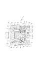
次に、本発明の一実施例のはすば遊星歯車減速機の構成を、図面にもとづいて説明する。図1は本実施例のはすば遊星歯車減速機の全体構成を表す断面図、図2は同実施例のはすば遊星歯車減速機における、スラスト軸受及び伏勢部材の構成を表す外観斜視図である。 Next, the configuration of a helical planetary gear reducer according to an embodiment of the present invention will be described with reference to the drawings. FIG. 1 is a cross-sectional view showing the overall configuration of the helical planetary gear reducer of this embodiment, and FIG. 2 is an external perspective view showing the configuration of the thrust bearing and the biasing member in the helical planetary gear reducer of the same embodiment. FIG.
図1に表したように、はすば遊星歯車減速機1は、図示されない駆動モータ(所謂、駆動源である。)の駆動力を受けて回動する回転軸2、回転軸2に接続され回転軸2と共に回動する太陽歯車3、太陽歯車3に空隙を介して同軸状に配設された内歯車6、前記空隙に配設され太陽歯車3及び内歯車6に螺合する遊星歯車5、遊星歯車5を連結ピン21を介して回転自在に支持すると共に太陽歯車3と同軸状に回転自在に支持された第一回動体7、第一回動体7のボス部7cに一体に接合された第二太陽歯車8、第二太陽歯車8に空隙を介して同軸状に配設された第二内歯車9、前記空隙に配設され第二太陽歯車8及び第二内歯車9に螺合する第ニ遊星歯車10、第ニ遊星歯車10を第ニ連結ピン22を介して回転自在に支持すると共に第ニ太陽歯車8と同軸状に回転自在に支持された第ニ回動体11、第ニ回動体11の端面から軸方向に延出した出力側回転軸26、ケーシング23、歯車機構の潤滑剤をシールするためのオイルシール25等を備えている。
As shown in FIG. 1, the helical planetary gear reducer 1 is connected to a rotating
回転軸2は、中空部26とネジ孔2aを備え、中空部26に駆動モータの回転軸(図示せず)が挿入され、ネジ孔2aを介して駆動モータの回転軸に固定される。
The
ケーシング23、内歯車6、第ニ内歯車9等は、ボルト24によって一体に固定されている。また、第ニ回動体11は、ベアリング18、19を介して、第一内歯車6、第ニ内歯車9に回動自在に支持されている。また、第一回動体7は、軸方向の一端側が、連結ピン21、遊星歯車5、太陽歯車3、回転軸2等を介して図示されない駆動モータの回転軸に連結し、軸方向の他端側が、第ニ太陽歯車8、第ニ遊星歯車10、第ニ連結ピン22、を介して第ニ回動体11に連結し、回転自在に支持されている。
The
また、太陽歯車3、内歯車6、遊星歯車5、第二太陽歯車8、第二内歯車9、第ニ遊星歯車10等は、回転駆動する際の騒音を低減するために、はすば歯車によって形成されている。
Further, the sun gear 3, the internal gear 6, the
また、本はすば遊星歯車減速機1は、第一回動体7に遊星歯車5とスラスト方向(所謂、本発明のスラスト方向とは回転軸に沿った方向である。)に重なるフランジ16を備えている。そして、はすば遊星歯車減速機1は、遊星歯車5にスラスト方向に貫通する貫通孔に回動自在に係合すると共に一端がフランジ16に固定された連結ピン21を備え、フランジ16を介して遊星歯車5の反対側において、フランジ16の端部に当接してフランジ16を回動自在にスラスト方向に支持する第一スラスト軸受12と、遊星歯車5を介してフランジ16の反対側において、連結ピン21の先端に当接してフランジ16を回動自在にスラスト方向に支持する第ニスラスト軸受13と、第一スラスト軸受12を第一回動体7に向かって伏勢する伏勢部材17とを備えている。また、遊星歯車5には軸受14が係合して軸受14に連結ピン21が挿通され、連結ピン21及び軸受14を介して、遊星歯車5がフランジ16に回動自在に支持されている。
Further, in the present helical planetary gear reducer 1, the first rotating body 7 is provided with a
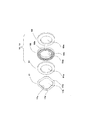
次に、図2に表したように、第一、第二スラスト軸受12、13は、環状部材52bと、環状部材52bに回転自在に支持された複数の円筒状ころ52cと、環状部材52bの軸方向の両側に配設され、円筒状ころ52cに回動自在に当接する一対のスライド板51、53と、によって構成されている。また、環状部材52b及びスライド板51、53には、第一回動体7のボス部(図1中の符号7c)が挿通可能な貫通孔52a、51a、53aが形成されている。また、スライド板51、53は、金属板によって形成され、円筒状ころ52c及び伏勢部材17との間のすべり摩擦を小さくするために、その表面が鏡面仕上げされている。
Next, as shown in FIG. 2, the first and
伏勢部材17は、例えば薄厚の金属板が用いられ、貫通孔17bを有するリング状に形成され、そのリング部17aには、厚み方向に波状に成形されて波状の頂部17c、17dが備えられている。
For example, a thin metal plate is used as the biasing
そして、図1に表したように、連結部Pの一端側(第ニ回動体側)において、第一回動体7及び第ニ回動体11が、第一スラスト軸受12及び伏勢部材17を介して、スラスト方向に対向する対向部Qを備え、伏勢部材17は、波状の頂部(図2中の符号17c)が第一スラスト軸受12のスライド板51に当接し、波状の頂部(図2中の符号17d)が第二回動体11に当接している。また、伏勢部材17の外周が第ニ回動部材11の内壁に沿って嵌合しており、伏勢部材17に設けられた貫通孔17bの内周と第一回動体7のボス部7cの外径とは、互いに接触することがないように間隙が構成されている。また、第一スラスト軸受12は、貫通孔(図2中の符号51a、52a、53a)に第一回動体7のボス部7cが挿入され、環状部材(図2中の符号52b)の外径と第ニ回動体11とは、互いに接触することがないように間隙が構成されている。
As shown in FIG. 1, the first rotating body 7 and the second
また、連結部Pの他端側(第ニ回動体11とは反対側)において、第二スラスト軸受13は、貫通孔(図2中の符号51a、52a、53a)に回転軸2が挿通されてケーシング23の内壁から中心に向かって突出した突出部23aと連結ピン21との間に装着され、環状部材52b及びスライド板51、53の外周がケーシング23の内周に沿って嵌合しており、回転軸2と第二スラスト軸受13の貫通孔(図2中の符号51a、52a、53a)の内周とは、互いに接触することがないように間隙が構成されている。また、第二スラスト軸受13と連結ピン21とが互いに接触することがないように、スラスト方向の間隙Cが構成されている。
Further, on the other end side of the connecting portion P (on the side opposite to the second rotating body 11), the second thrust bearing 13 has the
次に、前述のように構成されたはすば遊星歯車減速機1は、回転軸2を介して駆動モータの回転駆動力が伝達されると以下のように動作する。
Next, the helical planetary gear reducer 1 configured as described above operates as follows when the rotational driving force of the drive motor is transmitted via the
まず、回転軸2と一体に太陽歯車3が回動し、遊星歯車5が太陽歯車3の周囲に沿って公転すると共に連結ピン21を回転軸に自転する。そして、遊星歯車5の公転に伴って第一回動体7が回動する。
First, the sun gear 3 rotates integrally with the
次いで、第一回動体7と一体に第ニ太陽歯車8が回転し、第ニ遊星歯車10が第ニ太陽歯車8の周囲に沿って公転すると共に第ニ連結ピン22を回転軸に自転する。そして、第ニ遊星歯車10の公転に伴って第ニ回動体11が回転する。また、第ニ遊星歯車10は、貫通孔に軸受15が係合しており、軸受15を介して連結ピン22に回動自在に支持されている。連結ピン22は、両端が第ニ回動体11に固定されている。この際、第ニ太陽歯車8が第ニ遊星歯車10と螺合して回動することによって第一回動体7にスラスト力が加えられるが、スラスト軸受12、13及び伏勢部材17によってスラスト方向の変位が抑制されている。また、伏勢部材17は、第ニ回動体11に連れ回り第一スラスト軸受12を介して第一回動体7を回動自在に伏勢している。
Next, the second sun gear 8 rotates integrally with the first rotating body 7, the second
以下に、前記の構成を有する実施例の、はすば遊星歯車減速機1の作用効果を記載する。 Below, the effect of the helical planetary gear reducer 1 of the Example which has the said structure is described.
本実施例に記載のはすば遊星歯車減速機1によれば、第一回動体7には、遊星歯車5とスラスト方向に重なるフランジ16が備えられ、遊星歯車5のスラスト方向の貫通孔に回動自在に係合すると共に一端が前記フランジ16に固定された連結ピン21を備え、フランジ16を介して遊星歯車5の反対側において、フランジ16の端部に当接してフランジ16を回動自在にスラスト方向に支持する第一スラスト軸受12と、遊星歯車5を介してフランジ16の反対側において、連結ピン21の先端に当接してフランジ16を回動自在にスラスト方向に支持する第ニスラスト軸受13と、第一スラスト軸受12を第一回動体7に向かって伏勢する伏勢部材17とを備えているので、第二太陽歯車8と遊星歯車10との間にスラスト力が発現しても、第一回動体7のスラスト方向の変位を抑制でき、且つ、回転駆動力の損失も低減できる。また、本遊星歯車減速機1によれば、連結ピン21の先端を第二スラスト軸受13に当接させることにより、遊星歯車5を介してフランジ16と反対側に、第二スラスト軸受13に当接する当接部を第一回動体7に備える必要がなく、容易に第一回動体7を支持できる。
According to the helical planetary gear speed reducer 1 described in the present embodiment, the first rotating body 7 is provided with a
また、本実施例に記載のはすば遊星歯車減速機1によれば、連結ピン21の先端が遊星歯車5の端面より外方に突出し、第ニスラスト軸受13は、遊星歯車5とスラスト方向の間隙Cが構成されて離間しているので、第二スラスト軸受13と遊星歯車5との摩擦が生じることなく、遊星歯車5の回動を抑制することがない。
Further, according to the helical planetary gear speed reducer 1 described in the present embodiment, the front end of the connecting
また、本実施例に記載のはすば遊星歯車減速機1によれば、第一回動体7及び第ニ回動体11が、第一スラスト軸受12及び伏勢部材17を介してスラスト方向に対向する対向部Qを備え、伏勢部材17が、板状部材が波状に成形されてばね性を有する板ばねであって、波状の頂部が第一スラスト軸受12及び第二回動体11に当接するように構成されているので、互いの回動を抑制することなく第一回動体7と第ニ回動体11とのスラスト方向の相対位置が均一に維持される。
Further, according to the helical planetary gear speed reducer 1 described in the present embodiment, the first rotating body 7 and the second
以上、本発明の一実施例について説明したが、本発明は、上記実施例に限定されるものではなく、種々の態様をとることができる。 As mentioned above, although one Example of this invention was described, this invention is not limited to the said Example, It can take a various aspect.
例えば、本実施例のはすば遊星歯車減速機1において、第一、第二スラスト軸受12、13に円筒状ころ52cを備えたものを用いたが、円筒状ころ52cに限定されることなく、スラスト方向に荷重を受け回動可能な転動体であればよい。
For example, in the helical planetary gear speed reducer 1 of the present embodiment, the first and
また、伏勢部材17として金属板を波状に成形した板ばねを用いたが、第一スラスト軸受12をスラスト方向に弾性を有して伏勢でき、且つ、第一スラスト軸受12との摺動摩擦の小さなものであればよい。
Further, although a leaf spring formed of a metal plate in a wave shape is used as the biasing
1…はすば遊星歯車減速機、2…回転軸、2a…ネジ孔、3…太陽歯車、5…遊星歯車、6…内歯車、7…第一回動体、7a,7b…支持部、7c…ボス部、8…第二太陽歯車、9…第二内歯車、10…第ニ遊星歯車、11…第ニ回動体、12…第一スラスト軸受、13…第ニスラスト軸受、14,15…軸受、16…フランジ、17…伏勢部材、17a…リング部、17b…貫通孔、17c,17d…波状の頂部、18,19…ベアリング、21…連結ピン、22…第ニ連結ピン、23…ケーシング、24…ボルト、25…オイルシール、26…中空部、51,53…スライド板、51a,52a,53a…貫通孔、52b…環状部材、52c…円筒状ころ。
DESCRIPTION OF SYMBOLS 1 ... Helical planetary gear reducer, 2 ... Rotating shaft, 2a ... Screw hole, 3 ... Sun gear, 5 ... Planetary gear, 6 ... Internal gear, 7 ... First rotating body, 7a, 7b ... Support part, 7c DESCRIPTION OF SYMBOLS ... Boss part, 8 ... 2nd sun gear, 9 ... 2nd internal gear, 10 ... 2nd planetary gear, 11 ... 2nd rotating body, 12 ... 1st thrust bearing, 13 ... 1st varnish last bearing, 14, 15 ... bearing 16 ... Flange, 17 ... Biasing member, 17a ... Ring part, 17b ... Through hole, 17c, 17d ... Wave-shaped top part, 18, 19 ... Bearing, 21 ... Connection pin, 22 ... Second connection pin, 23 ...
Claims (3)
を備え、
前記太陽歯車、前記遊星歯車及び前記内歯車がはすば歯車で形成され、該太陽歯車の回転動作を、該遊星歯車を介して減速し、前記第一回動体に伝達するはすば遊星歯車減速機であって、
前記第一回動体には、前記遊星歯車とスラスト方向に重なるフランジが備えられ、
前記遊星歯車にスラスト方向に貫通する貫通孔に回動自在に係合すると共に、一端が前記フランジに固定された連結ピンを備え、
前記フランジを介して前記遊星歯車の反対側において、該フランジの端部に当接して該フランジを回動自在にスラスト方向に支持する第一スラスト軸受と、
前記遊星歯車を介して前記フランジの反対側において、前記連結ピンの先端に当接して該フランジを回動自在にスラスト方向に支持する第ニスラスト軸受と、
前記第一、第ニスラスト軸受の少なくとも一方を第一回動体に向かって伏勢する伏勢部材と、
を備えている、
ことを特徴とするはすば遊星歯車減速機。 A rotating shaft that rotates by receiving a driving force of a driving source; a sun gear that is connected to the rotating shaft and rotates together with the rotating shaft; and an internal gear that is coaxially disposed in the sun gear via a gap. A planetary gear disposed in the gap and screwed into the sun gear and the internal gear, a first rotating body rotatably supporting the planetary gear and coaxially rotating with the sun gear;
With
A helical planetary gear in which the sun gear, the planetary gear, and the internal gear are formed of a helical gear, and the rotational operation of the sun gear is decelerated through the planetary gear and transmitted to the first rotating body. A reduction gear,
The first rotating body includes a flange overlapping with the planetary gear in a thrust direction,
The planetary gear is rotatably engaged with a through-hole penetrating in the thrust direction, and has a connecting pin with one end fixed to the flange,
A first thrust bearing that contacts the end of the flange on the opposite side of the planetary gear through the flange and rotatably supports the flange in a thrust direction;
A first varnish bearing on the opposite side of the flange via the planetary gear, abutting the tip of the connecting pin and rotatably supporting the flange in a thrust direction;
A biasing member that biases at least one of the first and second varnish bearings toward the first rotating body;
With
A helical planetary gear reducer characterized by that.
ことを特徴とする請求項1に記載のはすば遊星歯車減速機。 The tip of the connecting pin protrudes outward from the end surface of the planetary gear, and the first varnish thrust bearing is separated from the planetary gear in the thrust direction.
The helical planetary gear reducer according to claim 1, wherein:
前記伏勢部材は、
板状部材が波状に成形されてばね性を有する板ばねであって、前記波状の頂部が前記スラスト軸受及び第二回動体に当接するように構成されている、
ことを特徴とする請求項1又は請求項2に記載のはすば遊星歯車減速機。 A second rotating body that is screwed to the first rotating body, and the first rotating body and the second rotating body have a facing portion that opposes the thrust direction via the thrust bearing and the biasing member; Prepared,
The prone member is
The plate-like member is a plate spring formed into a wave shape and has a spring property, and the wave-like top portion is configured to contact the thrust bearing and the second rotating body.
The helical planetary gear reducer according to claim 1 or 2, characterized in that
Priority Applications (1)
| Application Number | Priority Date | Filing Date | Title |
|---|---|---|---|
| JP2004112844A JP2005299718A (en) | 2004-04-07 | 2004-04-07 | Helical planetary gear reduction gear |
Applications Claiming Priority (1)
| Application Number | Priority Date | Filing Date | Title |
|---|---|---|---|
| JP2004112844A JP2005299718A (en) | 2004-04-07 | 2004-04-07 | Helical planetary gear reduction gear |
Publications (1)
| Publication Number | Publication Date |
|---|---|
| JP2005299718A true JP2005299718A (en) | 2005-10-27 |
Family
ID=35331501
Family Applications (1)
| Application Number | Title | Priority Date | Filing Date |
|---|---|---|---|
| JP2004112844A Pending JP2005299718A (en) | 2004-04-07 | 2004-04-07 | Helical planetary gear reduction gear |
Country Status (1)
| Country | Link |
|---|---|
| JP (1) | JP2005299718A (en) |
Cited By (1)
| Publication number | Priority date | Publication date | Assignee | Title |
|---|---|---|---|---|
| CN105370848A (en) * | 2015-09-29 | 2016-03-02 | 江苏金源锻造股份有限公司 | Flange shaft inside screw-type extruder transmission case |
-
2004
- 2004-04-07 JP JP2004112844A patent/JP2005299718A/en active Pending
Cited By (1)
| Publication number | Priority date | Publication date | Assignee | Title |
|---|---|---|---|---|
| CN105370848A (en) * | 2015-09-29 | 2016-03-02 | 江苏金源锻造股份有限公司 | Flange shaft inside screw-type extruder transmission case |
Similar Documents
| Publication | Publication Date | Title |
|---|---|---|
| JP4762643B2 (en) | Center crank type eccentric oscillating speed reducer | |
| AU2012370697B2 (en) | Continuously variable transmission | |
| JP4850129B2 (en) | Final reduction gear | |
| JP4590299B2 (en) | Carrier support structure for planetary gear reducer | |
| JP2009097664A (en) | Bush bearing | |
| TW200532124A (en) | Eccentrically swinging gear device | |
| JP2015183763A (en) | reduction gear | |
| JP2006307909A (en) | Rotary support structure of carrier in planetary gear reduction gear | |
| JP2013044406A (en) | Electric transmission and drive device for electric vehicle | |
| JP5203209B2 (en) | Continuously variable transmission | |
| KR101537002B1 (en) | Reducer have trochoid gear | |
| JP2024003284A (en) | Internal meshing planetary gear device and joint device for robots | |
| JP2005291426A (en) | Helical planetary gear speed reducer | |
| JP2005299718A (en) | Helical planetary gear reduction gear | |
| WO2015008487A1 (en) | Free-type bi-directional clutch | |
| JP2015132359A (en) | Speed reducer | |
| JP2016200218A (en) | Planetary roller type power transmission device | |
| WO2018052092A1 (en) | Gear assembly, planetary gear mechanism using gear assembly, and motor with built-in gear mechanism | |
| JP6568749B2 (en) | Planetary roller type power transmission device | |
| JP4889318B2 (en) | Lubricating structure of planetary reducer | |
| JP4672983B2 (en) | Reducer output section structure | |
| JP2008215478A (en) | Friction type transmission | |
| JP6314534B2 (en) | Friction roller reducer | |
| JP2007127156A (en) | Planetary gear power transmission device | |
| WO2016017437A1 (en) | Actuator for continuously variable transmission, and continuously variable transmission |