JP2005299631A - Automobile exhaust emission control system - Google Patents
Automobile exhaust emission control system Download PDFInfo
- Publication number
- JP2005299631A JP2005299631A JP2004307258A JP2004307258A JP2005299631A JP 2005299631 A JP2005299631 A JP 2005299631A JP 2004307258 A JP2004307258 A JP 2004307258A JP 2004307258 A JP2004307258 A JP 2004307258A JP 2005299631 A JP2005299631 A JP 2005299631A
- Authority
- JP
- Japan
- Prior art keywords
- ccc
- catalyst
- flow path
- exhaust gas
- purification system
- Prior art date
- Legal status (The legal status is an assumption and is not a legal conclusion. Google has not performed a legal analysis and makes no representation as to the accuracy of the status listed.)
- Pending
Links
Images
Classifications
-
- B—PERFORMING OPERATIONS; TRANSPORTING
- B01—PHYSICAL OR CHEMICAL PROCESSES OR APPARATUS IN GENERAL
- B01D—SEPARATION
- B01D53/00—Separation of gases or vapours; Recovering vapours of volatile solvents from gases; Chemical or biological purification of waste gases, e.g. engine exhaust gases, smoke, fumes, flue gases, aerosols
- B01D53/34—Chemical or biological purification of waste gases
- B01D53/92—Chemical or biological purification of waste gases of engine exhaust gases
- B01D53/94—Chemical or biological purification of waste gases of engine exhaust gases by catalytic processes
- B01D53/9495—Controlling the catalytic process
-
- F—MECHANICAL ENGINEERING; LIGHTING; HEATING; WEAPONS; BLASTING
- F01—MACHINES OR ENGINES IN GENERAL; ENGINE PLANTS IN GENERAL; STEAM ENGINES
- F01N—GAS-FLOW SILENCERS OR EXHAUST APPARATUS FOR MACHINES OR ENGINES IN GENERAL; GAS-FLOW SILENCERS OR EXHAUST APPARATUS FOR INTERNAL-COMBUSTION ENGINES
- F01N9/00—Electrical control of exhaust gas treating apparatus
-
- B—PERFORMING OPERATIONS; TRANSPORTING
- B01—PHYSICAL OR CHEMICAL PROCESSES OR APPARATUS IN GENERAL
- B01D—SEPARATION
- B01D53/00—Separation of gases or vapours; Recovering vapours of volatile solvents from gases; Chemical or biological purification of waste gases, e.g. engine exhaust gases, smoke, fumes, flue gases, aerosols
- B01D53/34—Chemical or biological purification of waste gases
- B01D53/92—Chemical or biological purification of waste gases of engine exhaust gases
- B01D53/94—Chemical or biological purification of waste gases of engine exhaust gases by catalytic processes
- B01D53/9445—Simultaneously removing carbon monoxide, hydrocarbons or nitrogen oxides making use of three-way catalysts [TWC] or four-way-catalysts [FWC]
- B01D53/9454—Simultaneously removing carbon monoxide, hydrocarbons or nitrogen oxides making use of three-way catalysts [TWC] or four-way-catalysts [FWC] characterised by a specific device
-
- F—MECHANICAL ENGINEERING; LIGHTING; HEATING; WEAPONS; BLASTING
- F01—MACHINES OR ENGINES IN GENERAL; ENGINE PLANTS IN GENERAL; STEAM ENGINES
- F01N—GAS-FLOW SILENCERS OR EXHAUST APPARATUS FOR MACHINES OR ENGINES IN GENERAL; GAS-FLOW SILENCERS OR EXHAUST APPARATUS FOR INTERNAL-COMBUSTION ENGINES
- F01N13/00—Exhaust or silencing apparatus characterised by constructional features
- F01N13/009—Exhaust or silencing apparatus characterised by constructional features having two or more separate purifying devices arranged in series
- F01N13/0097—Exhaust or silencing apparatus characterised by constructional features having two or more separate purifying devices arranged in series the purifying devices are arranged in a single housing
-
- F—MECHANICAL ENGINEERING; LIGHTING; HEATING; WEAPONS; BLASTING
- F01—MACHINES OR ENGINES IN GENERAL; ENGINE PLANTS IN GENERAL; STEAM ENGINES
- F01N—GAS-FLOW SILENCERS OR EXHAUST APPARATUS FOR MACHINES OR ENGINES IN GENERAL; GAS-FLOW SILENCERS OR EXHAUST APPARATUS FOR INTERNAL-COMBUSTION ENGINES
- F01N13/00—Exhaust or silencing apparatus characterised by constructional features
- F01N13/011—Exhaust or silencing apparatus characterised by constructional features having two or more purifying devices arranged in parallel
-
- F—MECHANICAL ENGINEERING; LIGHTING; HEATING; WEAPONS; BLASTING
- F01—MACHINES OR ENGINES IN GENERAL; ENGINE PLANTS IN GENERAL; STEAM ENGINES
- F01N—GAS-FLOW SILENCERS OR EXHAUST APPARATUS FOR MACHINES OR ENGINES IN GENERAL; GAS-FLOW SILENCERS OR EXHAUST APPARATUS FOR INTERNAL-COMBUSTION ENGINES
- F01N3/00—Exhaust or silencing apparatus having means for purifying, rendering innocuous, or otherwise treating exhaust
- F01N3/08—Exhaust or silencing apparatus having means for purifying, rendering innocuous, or otherwise treating exhaust for rendering innocuous
- F01N3/0807—Exhaust or silencing apparatus having means for purifying, rendering innocuous, or otherwise treating exhaust for rendering innocuous by using absorbents or adsorbents
- F01N3/0828—Exhaust or silencing apparatus having means for purifying, rendering innocuous, or otherwise treating exhaust for rendering innocuous by using absorbents or adsorbents characterised by the absorbed or adsorbed substances
- F01N3/0835—Hydrocarbons
-
- F—MECHANICAL ENGINEERING; LIGHTING; HEATING; WEAPONS; BLASTING
- F01—MACHINES OR ENGINES IN GENERAL; ENGINE PLANTS IN GENERAL; STEAM ENGINES
- F01N—GAS-FLOW SILENCERS OR EXHAUST APPARATUS FOR MACHINES OR ENGINES IN GENERAL; GAS-FLOW SILENCERS OR EXHAUST APPARATUS FOR INTERNAL-COMBUSTION ENGINES
- F01N3/00—Exhaust or silencing apparatus having means for purifying, rendering innocuous, or otherwise treating exhaust
- F01N3/08—Exhaust or silencing apparatus having means for purifying, rendering innocuous, or otherwise treating exhaust for rendering innocuous
- F01N3/0807—Exhaust or silencing apparatus having means for purifying, rendering innocuous, or otherwise treating exhaust for rendering innocuous by using absorbents or adsorbents
- F01N3/0828—Exhaust or silencing apparatus having means for purifying, rendering innocuous, or otherwise treating exhaust for rendering innocuous by using absorbents or adsorbents characterised by the absorbed or adsorbed substances
- F01N3/0842—Nitrogen oxides
-
- F—MECHANICAL ENGINEERING; LIGHTING; HEATING; WEAPONS; BLASTING
- F01—MACHINES OR ENGINES IN GENERAL; ENGINE PLANTS IN GENERAL; STEAM ENGINES
- F01N—GAS-FLOW SILENCERS OR EXHAUST APPARATUS FOR MACHINES OR ENGINES IN GENERAL; GAS-FLOW SILENCERS OR EXHAUST APPARATUS FOR INTERNAL-COMBUSTION ENGINES
- F01N3/00—Exhaust or silencing apparatus having means for purifying, rendering innocuous, or otherwise treating exhaust
- F01N3/08—Exhaust or silencing apparatus having means for purifying, rendering innocuous, or otherwise treating exhaust for rendering innocuous
- F01N3/0807—Exhaust or silencing apparatus having means for purifying, rendering innocuous, or otherwise treating exhaust for rendering innocuous by using absorbents or adsorbents
- F01N3/0871—Exhaust or silencing apparatus having means for purifying, rendering innocuous, or otherwise treating exhaust for rendering innocuous by using absorbents or adsorbents using means for controlling, e.g. purging, the absorbents or adsorbents
- F01N3/0878—Bypassing absorbents or adsorbents
-
- F—MECHANICAL ENGINEERING; LIGHTING; HEATING; WEAPONS; BLASTING
- F01—MACHINES OR ENGINES IN GENERAL; ENGINE PLANTS IN GENERAL; STEAM ENGINES
- F01N—GAS-FLOW SILENCERS OR EXHAUST APPARATUS FOR MACHINES OR ENGINES IN GENERAL; GAS-FLOW SILENCERS OR EXHAUST APPARATUS FOR INTERNAL-COMBUSTION ENGINES
- F01N3/00—Exhaust or silencing apparatus having means for purifying, rendering innocuous, or otherwise treating exhaust
- F01N3/08—Exhaust or silencing apparatus having means for purifying, rendering innocuous, or otherwise treating exhaust for rendering innocuous
- F01N3/10—Exhaust or silencing apparatus having means for purifying, rendering innocuous, or otherwise treating exhaust for rendering innocuous by thermal or catalytic conversion of noxious components of exhaust
- F01N3/18—Exhaust or silencing apparatus having means for purifying, rendering innocuous, or otherwise treating exhaust for rendering innocuous by thermal or catalytic conversion of noxious components of exhaust characterised by methods of operation; Control
- F01N3/20—Exhaust or silencing apparatus having means for purifying, rendering innocuous, or otherwise treating exhaust for rendering innocuous by thermal or catalytic conversion of noxious components of exhaust characterised by methods of operation; Control specially adapted for catalytic conversion
- F01N3/2006—Periodically heating or cooling catalytic reactors, e.g. at cold starting or overheating
-
- F—MECHANICAL ENGINEERING; LIGHTING; HEATING; WEAPONS; BLASTING
- F01—MACHINES OR ENGINES IN GENERAL; ENGINE PLANTS IN GENERAL; STEAM ENGINES
- F01N—GAS-FLOW SILENCERS OR EXHAUST APPARATUS FOR MACHINES OR ENGINES IN GENERAL; GAS-FLOW SILENCERS OR EXHAUST APPARATUS FOR INTERNAL-COMBUSTION ENGINES
- F01N3/00—Exhaust or silencing apparatus having means for purifying, rendering innocuous, or otherwise treating exhaust
- F01N3/08—Exhaust or silencing apparatus having means for purifying, rendering innocuous, or otherwise treating exhaust for rendering innocuous
- F01N3/10—Exhaust or silencing apparatus having means for purifying, rendering innocuous, or otherwise treating exhaust for rendering innocuous by thermal or catalytic conversion of noxious components of exhaust
- F01N3/18—Exhaust or silencing apparatus having means for purifying, rendering innocuous, or otherwise treating exhaust for rendering innocuous by thermal or catalytic conversion of noxious components of exhaust characterised by methods of operation; Control
- F01N3/20—Exhaust or silencing apparatus having means for purifying, rendering innocuous, or otherwise treating exhaust for rendering innocuous by thermal or catalytic conversion of noxious components of exhaust characterised by methods of operation; Control specially adapted for catalytic conversion
- F01N3/2053—By-passing catalytic reactors, e.g. to prevent overheating
-
- B—PERFORMING OPERATIONS; TRANSPORTING
- B01—PHYSICAL OR CHEMICAL PROCESSES OR APPARATUS IN GENERAL
- B01D—SEPARATION
- B01D2255/00—Catalysts
- B01D2255/20—Metals or compounds thereof
- B01D2255/202—Alkali metals
- B01D2255/2022—Potassium
-
- B—PERFORMING OPERATIONS; TRANSPORTING
- B01—PHYSICAL OR CHEMICAL PROCESSES OR APPARATUS IN GENERAL
- B01D—SEPARATION
- B01D2255/00—Catalysts
- B01D2255/50—Zeolites
-
- B—PERFORMING OPERATIONS; TRANSPORTING
- B01—PHYSICAL OR CHEMICAL PROCESSES OR APPARATUS IN GENERAL
- B01D—SEPARATION
- B01D2255/00—Catalysts
- B01D2255/90—Physical characteristics of catalysts
- B01D2255/91—NOx-storage component incorporated in the catalyst
-
- B—PERFORMING OPERATIONS; TRANSPORTING
- B01—PHYSICAL OR CHEMICAL PROCESSES OR APPARATUS IN GENERAL
- B01D—SEPARATION
- B01D2255/00—Catalysts
- B01D2255/90—Physical characteristics of catalysts
- B01D2255/912—HC-storage component incorporated in the catalyst
-
- F—MECHANICAL ENGINEERING; LIGHTING; HEATING; WEAPONS; BLASTING
- F01—MACHINES OR ENGINES IN GENERAL; ENGINE PLANTS IN GENERAL; STEAM ENGINES
- F01N—GAS-FLOW SILENCERS OR EXHAUST APPARATUS FOR MACHINES OR ENGINES IN GENERAL; GAS-FLOW SILENCERS OR EXHAUST APPARATUS FOR INTERNAL-COMBUSTION ENGINES
- F01N13/00—Exhaust or silencing apparatus characterised by constructional features
- F01N13/14—Exhaust or silencing apparatus characterised by constructional features having thermal insulation
-
- F—MECHANICAL ENGINEERING; LIGHTING; HEATING; WEAPONS; BLASTING
- F01—MACHINES OR ENGINES IN GENERAL; ENGINE PLANTS IN GENERAL; STEAM ENGINES
- F01N—GAS-FLOW SILENCERS OR EXHAUST APPARATUS FOR MACHINES OR ENGINES IN GENERAL; GAS-FLOW SILENCERS OR EXHAUST APPARATUS FOR INTERNAL-COMBUSTION ENGINES
- F01N2410/00—By-passing, at least partially, exhaust from inlet to outlet of apparatus, to atmosphere or to other device
- F01N2410/02—By-passing, at least partially, exhaust from inlet to outlet of apparatus, to atmosphere or to other device in case of high temperature, e.g. overheating of catalytic reactor
-
- F—MECHANICAL ENGINEERING; LIGHTING; HEATING; WEAPONS; BLASTING
- F01—MACHINES OR ENGINES IN GENERAL; ENGINE PLANTS IN GENERAL; STEAM ENGINES
- F01N—GAS-FLOW SILENCERS OR EXHAUST APPARATUS FOR MACHINES OR ENGINES IN GENERAL; GAS-FLOW SILENCERS OR EXHAUST APPARATUS FOR INTERNAL-COMBUSTION ENGINES
- F01N2570/00—Exhaust treating apparatus eliminating, absorbing or adsorbing specific elements or compounds
- F01N2570/12—Hydrocarbons
-
- F—MECHANICAL ENGINEERING; LIGHTING; HEATING; WEAPONS; BLASTING
- F01—MACHINES OR ENGINES IN GENERAL; ENGINE PLANTS IN GENERAL; STEAM ENGINES
- F01N—GAS-FLOW SILENCERS OR EXHAUST APPARATUS FOR MACHINES OR ENGINES IN GENERAL; GAS-FLOW SILENCERS OR EXHAUST APPARATUS FOR INTERNAL-COMBUSTION ENGINES
- F01N2570/00—Exhaust treating apparatus eliminating, absorbing or adsorbing specific elements or compounds
- F01N2570/14—Nitrogen oxides
-
- F—MECHANICAL ENGINEERING; LIGHTING; HEATING; WEAPONS; BLASTING
- F01—MACHINES OR ENGINES IN GENERAL; ENGINE PLANTS IN GENERAL; STEAM ENGINES
- F01N—GAS-FLOW SILENCERS OR EXHAUST APPARATUS FOR MACHINES OR ENGINES IN GENERAL; GAS-FLOW SILENCERS OR EXHAUST APPARATUS FOR INTERNAL-COMBUSTION ENGINES
- F01N3/00—Exhaust or silencing apparatus having means for purifying, rendering innocuous, or otherwise treating exhaust
- F01N3/08—Exhaust or silencing apparatus having means for purifying, rendering innocuous, or otherwise treating exhaust for rendering innocuous
- F01N3/0807—Exhaust or silencing apparatus having means for purifying, rendering innocuous, or otherwise treating exhaust for rendering innocuous by using absorbents or adsorbents
- F01N3/0814—Exhaust or silencing apparatus having means for purifying, rendering innocuous, or otherwise treating exhaust for rendering innocuous by using absorbents or adsorbents combined with catalytic converters, e.g. NOx absorption/storage reduction catalysts
-
- Y—GENERAL TAGGING OF NEW TECHNOLOGICAL DEVELOPMENTS; GENERAL TAGGING OF CROSS-SECTIONAL TECHNOLOGIES SPANNING OVER SEVERAL SECTIONS OF THE IPC; TECHNICAL SUBJECTS COVERED BY FORMER USPC CROSS-REFERENCE ART COLLECTIONS [XRACs] AND DIGESTS
- Y02—TECHNOLOGIES OR APPLICATIONS FOR MITIGATION OR ADAPTATION AGAINST CLIMATE CHANGE
- Y02A—TECHNOLOGIES FOR ADAPTATION TO CLIMATE CHANGE
- Y02A50/00—TECHNOLOGIES FOR ADAPTATION TO CLIMATE CHANGE in human health protection, e.g. against extreme weather
- Y02A50/20—Air quality improvement or preservation, e.g. vehicle emission control or emission reduction by using catalytic converters
-
- Y—GENERAL TAGGING OF NEW TECHNOLOGICAL DEVELOPMENTS; GENERAL TAGGING OF CROSS-SECTIONAL TECHNOLOGIES SPANNING OVER SEVERAL SECTIONS OF THE IPC; TECHNICAL SUBJECTS COVERED BY FORMER USPC CROSS-REFERENCE ART COLLECTIONS [XRACs] AND DIGESTS
- Y02—TECHNOLOGIES OR APPLICATIONS FOR MITIGATION OR ADAPTATION AGAINST CLIMATE CHANGE
- Y02T—CLIMATE CHANGE MITIGATION TECHNOLOGIES RELATED TO TRANSPORTATION
- Y02T10/00—Road transport of goods or passengers
- Y02T10/10—Internal combustion engine [ICE] based vehicles
- Y02T10/12—Improving ICE efficiencies
Landscapes
- Engineering & Computer Science (AREA)
- Chemical & Material Sciences (AREA)
- Combustion & Propulsion (AREA)
- Mechanical Engineering (AREA)
- General Engineering & Computer Science (AREA)
- Chemical Kinetics & Catalysis (AREA)
- Health & Medical Sciences (AREA)
- Analytical Chemistry (AREA)
- Environmental & Geological Engineering (AREA)
- General Chemical & Material Sciences (AREA)
- Oil, Petroleum & Natural Gas (AREA)
- Biomedical Technology (AREA)
- Toxicology (AREA)
- Exhaust Gas After Treatment (AREA)
- Exhaust Silencers (AREA)
- Exhaust Gas Treatment By Means Of Catalyst (AREA)
Abstract
Description
本発明は、自動車排気ガス浄化システムに関し、エンジン排気マニフォールド近くに設けられるCCC(Close Catalytic Converter)と、車体フロアの下側に設けられるUCC(Underfloor Catalytic Converter)と、CCC内に貴金属担持量が低いHC吸着触媒とNOx吸着触媒を設ける一方、バイパス流路と流路切換手段を含む可変流路システムを備えることを特徴とする自動車排気ガス浄化システムに関する。 The present invention relates to an automobile exhaust gas purification system, and a CCC (Close Catalytic Converter) provided near an engine exhaust manifold, a UCC (Underfloor Catalytic Converter) provided under a vehicle body floor, and a low amount of noble metal supported in the CCC. The present invention relates to an automobile exhaust gas purification system comprising a variable flow path system including a bypass flow path and a flow path switching means while providing an HC adsorption catalyst and a NO x adsorption catalyst.
自動車の排気ガスは、エンジンで混合器の燃焼によって生成され、排気パイプを介して大気中に放出されるガスであり、排気ガスには一酸化炭素(CO)、窒素酸化物(NOx)、未燃焼炭化水素(HC)など、人体に有害な物質が多量含まれている。
したがって、自動車排気ガスによる大気汚染を防止することが環境衛生上重要な問題とされており、自動車では排気ガスを排出する前に必ず浄化処理を行うよう規制している。
Automobile exhaust gas is a gas generated by the combustion of a mixer in an engine and released into the atmosphere through an exhaust pipe, and the exhaust gas includes carbon monoxide (CO), nitrogen oxides (NO x ), Contains a lot of substances harmful to human body such as unburned hydrocarbon (HC).
Therefore, prevention of air pollution caused by automobile exhaust gas is regarded as an important problem for environmental hygiene, and automobiles are regulated to perform purification treatment before exhaust gas is discharged.
自動車において排気ガスを浄化するために主に用いられる装置は、3元触媒(three way catalyst)を用いた触媒コンバーターであるが、これは排気パイプの途中に取り付けられ、車両によって排気ガス排出量が異なるため、触媒の仕様は異なる。
ここで、3元触媒は、排気ガスの有害成分である一酸化炭素、窒素酸化物及び炭化水素系化合物と同時に反応してこれらの化合物を除去する触媒を意味し、主にPt(白金)/Rh(ロジウム)、Pd(パラジウム)/RhまたはPt/Pd/Rh系の3元触媒が使用される。
一方、ガソリン乗用車の場合、排気ガスの後処理装置として大部分車体フロアの下側に設けられる触媒コンバーター、すなわちUCC(Underfloor Catalytic Converter)が適用されており、現在浄化率を高めるために触媒の体積を大きくする趨勢にあるが、車体の地上高が低いため、横断面形状が左右両側方に長く形成された楕円形(oval or racetrack形態)の触媒が主に使用されている。
A device mainly used for purifying exhaust gas in an automobile is a catalytic converter using a three-way catalyst, which is attached in the middle of an exhaust pipe, and the exhaust gas emission amount is reduced by the vehicle. The catalyst specifications are different because they are different.
Here, the three-way catalyst means a catalyst that removes these compounds by reacting simultaneously with carbon monoxide, nitrogen oxides, and hydrocarbon compounds, which are harmful components of exhaust gas, and mainly contains Pt (platinum) / Rh (rhodium), Pd (palladium) / Rh or Pt / Pd / Rh three-way catalysts are used.
On the other hand, in the case of a gasoline passenger car, a catalytic converter, that is, a UCC (Underfloor Catalytic Converter) provided mostly under the vehicle body floor is applied as an exhaust gas aftertreatment device, and the volume of the catalyst is currently increased in order to increase the purification rate. However, since the ground clearance of the vehicle body is low, an oval (or or racetrack) catalyst whose cross-sectional shape is long on both the left and right sides is mainly used.
現在、前記ガソリン車両の排気ガス浄化システムの最大目標は初期始動時の有害成分の排出を最小にすることである。初期始動時には排気ガスが触媒を通過するが、触媒が十分ウォーミングアップ(warm−up)されていない状態であり、触媒の温度が排気ガスの有害成分を無害に変換できるほど十分に高くない状態であるため、初期始動時の有害成分の排出を最小にするには、触媒の温度を出来るだけ速く昇温させることが必要である。
特に、全体的にHC及びNoxの2/3以上が初期始動時である触媒が十分ウォーミングアップされていない状態で排出されるので、初期始動時のHC及びNoxの低減が排気ガス低減技術の最優先課題となっている。
Currently, the maximum goal of the exhaust purification system of the gasoline vehicle is to minimize the emission of harmful components during initial start-up. Exhaust gas passes through the catalyst at initial start-up, but the catalyst is not warmed up sufficiently and the catalyst temperature is not high enough to convert the harmful components of the exhaust gas harmlessly Therefore, in order to minimize the discharge of harmful components at the initial start, it is necessary to raise the temperature of the catalyst as quickly as possible.
In particular, since two-thirds or more of the overall HC and No x are discharged in a state in which the catalyst is at the initial startup is not sufficiently warm-up, reduced during initial startup HC and No x is the exhaust gas reduction technology It is a top priority issue.
このため、触媒コンバーターをエンジンの排気マニフォールドに最大限近く設けるか(CCC:Close Catalytic Converter)、または特開平9−222009号及び特開平5−86845号に開示されているように、電気的に或いは燃焼によって触媒を加熱して強制的にウォーミングアップさせる方法が提案されている(EHC: Electrically Heated Catalyst, BHC:Burner Heated Catalyst)。
また他の方法としては、CCCの触媒に貴金属担持量を高めて触媒自体のウォーミングアップ時間を短縮させるか、触媒の熱容量を減らすために超薄壁担体や金属担体を使用する方法もあり、熱損失を減らすために二重管パイプ或いは二重管排気マニフォールドを適用する方法もある。
For this reason, a catalytic converter should be provided as close as possible to the engine exhaust manifold (CCC: Close Catalytic Converter), or as disclosed in JP-A-9-222009 and JP-A-5-86845, or A method of forcibly warming up by heating a catalyst by combustion has been proposed (EHC: Electrically Heated Catalyst, BHC: Burner Heated Catalyst).
Other methods include increasing the amount of noble metal supported on the CCC catalyst to shorten the warm-up time of the catalyst itself, or using an ultra-thin wall support or metal support to reduce the heat capacity of the catalyst, and heat loss. There is also a method of applying a double-pipe pipe or a double-pipe exhaust manifold in order to reduce this.
しかし、このような従来の排気ガス浄化システムには次のような問題がある。
まず、CCCのように触媒をエンジン側に近く位置する場合では、触媒の耐久性及び耐熱性に悪い影響を与えるという問題がある。
また、EHCやBHCの場合は、過多な電気容量(バッテリーやオルタネーター)を要求しており、また、触媒の加熱のために別途の燃料を使用する必要があり、触媒に甚だしい熱を加えて触媒に致命的な熱的損傷を与えることもある。
触媒の貴金属担持量を高める場合には、高価な貴金属使用量が増えるため、触媒の製造コストが高くなるという問題がある。
First, when the catalyst is located close to the engine side as in CCC, there is a problem in that the durability and heat resistance of the catalyst are adversely affected.
In the case of EHC and BHC, too much electric capacity (battery and alternator) is required, and it is necessary to use a separate fuel for heating the catalyst. May cause fatal thermal damage.
When the amount of noble metal supported on the catalyst is increased, the amount of expensive noble metal used increases, which causes a problem that the manufacturing cost of the catalyst increases.
本発明は、前記のような問題を解決するためになされたものであって、CCCとUCCを設けるが、CCC内には貴金属担持量が低いHC吸着触媒とNOx吸着触媒を設ける。一方、バイパス流路と流路切換手段を含む可変流路システムを備えることによって、初期始動時にはCCC内の前記吸着触媒に排気ガスが流れるようにしてこれらの吸着触媒が排気ガスを浄化するようにし、以降後方UCC触媒のウォーミングアップ状態ではCCC内の吸着触媒への流路は遮断し、UCC触媒にのみ排気ガスが流れるようにする。これにより、該UCC触媒が正常に排気ガスを浄化するようにして、浄化性能の向上はもちろん、貴金属をほとんど使用しないHC吸着触媒及びNOx吸着触媒をCCC内に使用することで、製造コストの節減が可能となる。また、可変流路を用いてCCC触媒を始動初期にのみ短時間使用するので、CCC触媒の耐熱性及び耐久性の問題が生じない。
すなわち、本発明は、排気ガスの浄化能力が高く、製造コスト低減が可能で、CCC触媒の耐熱性及び耐久性のよい自動車排気ガス浄化システムを提供することにその目的がある。
The present invention was made to solve the above problems, but providing the CCC and UCC, is in the CCC provided support amount of precious metal is lower HC adsorbing catalyst and the NO x adsorption catalyst. On the other hand, by providing the variable flow path system including the bypass flow path and the flow path switching means, the exhaust gas flows through the adsorption catalyst in the CCC at the initial start so that the adsorption catalyst purifies the exhaust gas. Thereafter, in the warming-up state of the rear UCC catalyst, the flow path to the adsorption catalyst in the CCC is shut off so that the exhaust gas flows only through the UCC catalyst. As a result, the UCC catalyst normally purifies the exhaust gas, so that not only the purification performance is improved, but also the HC adsorption catalyst and the NO x adsorption catalyst that use almost noble metal are used in the CCC. Savings are possible. In addition, since the CCC catalyst is used for a short time only at the beginning of the start using the variable flow path, there is no problem of heat resistance and durability of the CCC catalyst.
That is, an object of the present invention is to provide an automobile exhaust gas purification system that has a high exhaust gas purification capability, can reduce manufacturing costs, and has good heat resistance and durability of a CCC catalyst.
本発明は、自動車排気ガス浄化システムであって、ハウジング内部にHC吸着触媒とNOx吸着触媒が直列に内装されて排気経路上でエンジン排気マニフォールドの方に近く設けられ、排気ガスが前記2つの吸着触媒を介さずに直ちに排出されるようにするバイパス流路を有するCCCと;該CCCの後方に車体フロアの下側の排気パイプの途中に設けられるUCCと;前記UCC内の触媒の温度を検出するための温度感知センサと;該温度感知センサの信号を入力され、既に設定された温度以上の場合、前記UCC内の触媒のウォーミングアップ状態であることを判断して前記CCC内の排気経路を前記バイパス流路に切り換えるための制御信号を出力するECUと;該ECUの制御信号によって前記CCC内の吸着触媒側の流路とバイパス流路間の排気経路を切り換える流路切換手段と;を含むことを特徴とする。 The present invention is an automobile exhaust gas purification system, in which an HC adsorption catalyst and a NO x adsorption catalyst are installed in series inside a housing and provided close to an engine exhaust manifold on an exhaust path. A CCC having a bypass flow path that is immediately discharged without passing through an adsorbing catalyst; a UCC provided in the middle of an exhaust pipe below the vehicle body floor behind the CCC; and a temperature of the catalyst in the UCC A temperature detection sensor for detecting; when a signal of the temperature detection sensor is input and the temperature is already set or higher, it is determined that the catalyst in the UCC is warming up and the exhaust path in the CCC is An ECU for outputting a control signal for switching to the bypass flow path; a flow path on the adsorption catalyst side in the CCC and a bypass by the control signal of the ECU; And a flow path switching means for switching an exhaust path between the gas flow paths.
本発明に係る自動車排気ガス浄化システムによれば、UCC触媒が正常に排気ガスを浄化するようにすることによって、浄化性能の向上はもちろん、貴金属をほとんど使用しないHC吸着触媒及びNOx吸着触媒をCCC内に使用することによって、製造コストの節減が可能であり、可変流路を用いてCCC触媒を始動初期にのみ短時間使用するので、CCC触媒の耐熱性及び耐久性の問題が生じないという効果がある。 According to the automobile exhaust gas purification system of the present invention, by making the UCC catalyst normally purify the exhaust gas, the purification performance is improved, as well as the HC adsorption catalyst and the NO x adsorption catalyst that use almost noble metal. By using it in the CCC, it is possible to reduce the manufacturing cost, and because the CCC catalyst is used for a short time only at the beginning of the start using the variable flow path, there is no problem with the heat resistance and durability of the CCC catalyst. effective.
以下、添付の図面を参照して本発明を詳しく説明する。 Hereinafter, the present invention will be described in detail with reference to the accompanying drawings.
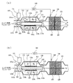
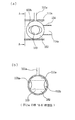
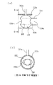
図1(a)及び図1(b)は、本発明に係る排気ガス浄化システムの構成及び作動状態を示す断面図であり、図2(a)及び図2(b)、図3(a)及び図3(b)は本発明において、ボールバルブの回転位置によるCCC入口通路の流路開閉状態を示す断面図である。
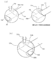
また、図4(a)及び図4(b)は、本発明において、ボールバルブの回転位置による中間パイプ流路の開閉状態を示す斜視図である。
1 (a) and 1 (b) are sectional views showing the configuration and operating state of the exhaust gas purification system according to the present invention, and FIG. 2 (a), FIG. 2 (b), and FIG. 3 (a). FIG. 3B is a cross-sectional view showing the open / close state of the CCC inlet passage according to the rotational position of the ball valve in the present invention.
4 (a) and 4 (b) are perspective views showing the open / close state of the intermediate pipe flow path according to the rotational position of the ball valve in the present invention.
図示するように、エンジンの排気マニフォールドからの排気ガスを大気に放出するための車体後尾までの排気経路上にCCC110とUCC120が直列配置される。
従来と同様に、CCC110は排気経路上で排気マニフォールドに出来る限り近く設け、UCC120は車体フロアの下側に位置する排気パイプの途中に設ける。UCC120を排気マニフォールド側に近接して設けることも可能であり、この際、UCC120は第2CCCと称する。
CCC110は、ハウジング111の内部にHC吸着触媒112とNOx吸着触媒113を前後直列配置する。前方に位置するHC吸着触媒112としては、ゼオライト系触媒としてAl/Si比が非常に低いため耐熱性が大きい触媒を使用することが好ましく、その後方のNOx吸着触媒113にはカリウム系触媒を使用してもよい。
As shown in the figure, a
As in the prior art, the CCC 110 is provided as close as possible to the exhaust manifold on the exhaust path, and the UCC 120 is provided in the middle of the exhaust pipe located below the vehicle body floor. It is also possible to provide the UCC 120 close to the exhaust manifold side, and in this case, the UCC 120 is referred to as a second CCC.
In the
また、各吸着触媒112,113の中央には、CCC入口通路111aを介して入った排気ガスを2つの吸着触媒112,113を通過せずに直ちにCCC出口通路111bを介して排出させて一種のバイパス流路として、中間パイプ114を縦方向に貫設させる。
中間パイプ114は、CCC110内の2つの吸着触媒112,113の中央ホール112a,113aを介して前後に長く挿設され、CCCハウジング111の内部を通過して、その入口と出口がそれぞれCCC吸着触媒112,113の前方と後方、より明確には、CCCハウジング111の入口通路111aと出口通路111bに位置する流路を形成する。特に、中間パイプ114の内部に流れる排気ガスはCCC内のHC吸着触媒112とNOx吸着触媒113を通過せずに直ちにCCC110の後端に排出された後UCC120に流れるようになる。
なお、2つの吸着触媒112,113の中央ホール112a,113aの内面と中間パイプ114の外面との間にはインシュレータ(insulator;115)が設けられる。
Further, in the center of each of the
The
An insulator (115) is provided between the inner surfaces of the
一方、UCC120は、ハウジング121の内部に従来と同様に2つの触媒、すなわち第1触媒122と第2触媒123を前後直列に配置してもよく、第1触媒122には温度感知センサ130が設けられる。
温度感知センサ130は第1触媒122の温度を検出し、それによる電気的信号を出力するもので、これはUCC触媒のウォーミングアップ状態を感知するための手段となる。
温度感知センサ130は熱電対(thermocouple)で、この際、第1触媒122の担体に別途の挿入空間を設け、該挿入空間に熱電対を長く挿入する。
On the other hand, the UCC 120 may have two catalysts, that is, the
The
The
また、本発明に係る排気ガス浄化システムはCCC110のハウジング111の内部で中間パイプ114によって区分される2つの流路、すなわち中間パイプ114の内側の内部流路114aと中間パイプ114の外側の外部流路116間で排気ガスの流れを切り換える流路切換手段150を含む。流路切換手段150はUCC120内の温度感知センサ130の出力信号を受けてUCC触媒122のウォーミングアップ状態を判断するECU140の制御信号によって駆動が制御される。
流路切換手段150はECU140の制御信号によって駆動が制御されるモータ151と、モータ151の駆動によって2つの流路114a,116間の排気ガスの流れを切り換えるバルブ152を含む。
In addition, the exhaust gas purification system according to the present invention is divided into two flow paths divided by the
The flow path switching means 150 includes a
好ましい実施形態として、バルブ152はモータ151の回転軸151aの先端に固定設置されたボールバルブで実施可能であり、このようなボールバルブ152を採用した流路切換手段150についてさらに詳しく説明すると次の通りである。
まず、モータ151はCCC入口通路111aの外側にCCCハウジング111または隣りの車体側の所定位置に取り付けられ、ボールバルブ152はCCC入口通路111aの内部に設けられる。
この際、CCC入口通路111aの内径と同一直径のボールバルブ152が用いられるが、ボールバルブ152はCCC入口通路111aを塞いでいる状態で中間パイプ114の前端入口に位置するように設けられる。
As a preferred embodiment, the
First, the
At this time, a
また、モータ151の回転軸151aの先端がボールバルブ152の上端中心に連結され、モータ151によりボールバルブ152が回転するようになっている。
ボールバルブ152は中央を貫通して形成したガス流路153を有し、ガス流路153の両端部側には内側に凹んだ形状の凹部153a,153bが形成されている。後述のように、ガス流路153と中間パイプ114が互いに横方向に配置されるボールバルブの位置では、凹部153a,153bがボールバルブ152の両側方でCCC入口通路111aの内面と排気ガス流路を形成するようになっている(図2(a)及び図2(b)参照)。
The tip of the
The
このような流路切換手段150では、ボールバルブ152の回転位置に応じて流路の切り換えがなされる。モータ151はECU140から出力される制御信号で駆動されボールバルブ152を回転軸151aを介して0°または90°位置に回転させて流路114a,116間の切り換えを行う。0°から360°に回転しながら流路を切り換えることが可能である。
ボールバルブ152が0°位置にある場合(初期始動時である)、中間パイプ114の内部流路114aがボールバルブ152によって遮断され、中間パイプ114外部の流路116が開く状態となる。図2(a)及び図2(b)に示すように、ボールバルブ152のガス流路153が中間パイプ114とは横方向に配置されるとともに中間パイプ114の前端入口がボールバルブ152によって塞がれた状態となる。また、ガス流路153の両端部側には凹部153a,153bによってCCC入口通路111aの内面とボールバルブ152との間に排気ガスが通過できる流路が生じるようになる。
In such a flow path switching means 150, the flow path is switched according to the rotational position of the
When the
また、凹部153a,153bなしでも、ガス流路のサイズ及び形状によって中間パイプ114とガス流路113を横方向に配置する場合、CCC入口通路の内面とガス流路の両端部の間に流路が形成される。この空間を通過した排気ガスは、中間パイプ114外側のHC吸着触媒112とNOx吸着触媒113を順次通過した後、CCC出口通路111bを介して排出され、排気パイプを介してUCC120に流れるようになる。
Further, even when the
反面、ボールバルブ152がモータの駆動によって90°位置に回転した状態(UCC触媒のウォーミングアップ状態)では、中間パイプ114外部の流路116がボールバルブ152によって遮断され、中間パイプ114の内部流路114aが開く状態となる。図3(a)及び図3(b)に示すように、ボールバルブ152のガス流路153が中間パイプ114と同一方向に配置され、中間パイプ114の前端入口がボールバルブ152によって開くとともに、ボールバルブ152のガス流路153と中間パイプ114の内部流路114aが互いに連結された状態となる。
On the other hand, when the
この状態では、CCC入口通路111aから入った排気ガスがボールバルブ152のガス流路153及び中間パイプ114の内部流路114aを順次通過した後、CCC出口通路111bを経て排気パイプに排出されUCC120に流れるようになる。
すなわち、ボールバルブ152が90°回転位置に置かれた状態では、中間パイプ114外部の流路116が遮断されることにより、CCC入口通路111aから入った排気ガスがHC吸着触媒112とNOx吸着触媒113を通過せずにUCC120に流れるようになる。
本発明の他の実施形態では、ボールバルブの位置が0°であるとき、ボールバルブのガス流路153と中間パイプ114の内部流路が連結されるようにし、90°であるとき、中間パイプ114の内部流路114aがボールバルブ152によって遮断され、中間パイプ114の外部の流路116が開くように設定することもできる。
In this state, exhaust gas entering from the
That is, in a state in which the
In another embodiment of the present invention, when the position of the ball valve is 0 °, the
排気ガス流路の切り換え状態を図4(a)及び図4(b)の斜視図を介して説明する。
ボールバルブ152のガス流路153が中間パイプ114と横方向に配置された状態(ボールバルブの0°位置)では、ガス流路153の両端部側の凹部153a,153bを通過して中間パイプの外側流路116に排気ガスが流れるようになる(図4(a))。その後ボールバルブ152が90°回転してガス流路153が中間パイプ114と同一方向に配置される場合、ガス流路153と中間パイプの内部流路114aを介して排気ガスが流れるようになる。
The switching state of the exhaust gas passage will be described with reference to the perspective views of FIGS. 4 (a) and 4 (b).
In a state where the
図4(a)及び図4(b)において、図面符号114bは中間パイプ114の前端入口で両側方に形成された羽根部であり、羽根部114bはガス流路153の後端部側の凹部153bを完全に覆うようになる。
すなわち、ボールバルブ152において凹部153a,153bは両側方に広く形成されているが、ガス流路153を通過した排気ガスが外部に漏れず、中間パイプ114の内部にすべて流れるようにするためには、羽根部114bがボールバルブ152の後端部側の凹部153bを完全に覆う必要がある。
また、ボールバルブ152が回転するとき、ボールバルブ152の表面が中間パイプ114の羽根部114bの前面と互いに接触した状態でスライドしなければ排気ガスが漏れるため、羽根部114bはボールバルブ152の表面曲率と同じ曲率の曲面とする必要がある。
4A and 4B,
That is, in the
Further, when the
以下、本発明に係る排気ガス浄化システムの全体的な作動状態を説明する。
本発明の排気ガス浄化システムは、可変流路を適用し、初期始動時にはCCC110内のHC吸着触媒112及びNOx吸着触媒113に排気ガスが流れるようにしてこれらを介して排気ガスが浄化されるようにし、以降、後方のUCC120内の触媒122,123が十分にウォーミングアップ状態(例、触媒温度が200℃以上)になった場合は、HC吸着触媒112及びNOx吸着触媒113への流路116は遮断し、UCC120内の触媒にのみ排気ガスが流れるようにし、UCC120が正常に排気ガスを浄化するようにしたシステムである。
Hereinafter, the overall operation state of the exhaust gas purification system according to the present invention will be described.
The exhaust gas purification system of the present invention applies a variable flow path so that the exhaust gas flows through the
まず、始動がかかるとエンジンから排気ガスが排出される。
この際、ボールバルブ152の状態は図2(a)、図2(b)及び図4(a)の状態となって、中央の排気ガス流路、すなわち中間パイプ114の内部流路114aが前端入口側でボールバルブ152によって塞がれて遮断され、ボールバルブ152の左右側の凹部153a,153bの流路が開くようになる。
該流路を通り排気ガスはCCC110内で中間パイプの外部の流路116に流れてHC吸着触媒112とNOx吸着触媒113を順次通過するようになり、その後、CCC出口通路111bを通って排気パイプに排出されてUCC120を通過するようになる(図1(a)における矢印P1の経路である)。
First, when starting, exhaust gas is discharged from the engine.
At this time, the state of the
The exhaust gas passes through the flow path and flows through the
ここで、排気ガスは2つの吸着触媒112,113を通過しながら排気ガス成分中のHCとNoxは各吸着触媒に吸着され、UCC120にはHCとNoxが除去された状態の排気ガスが流れるようになる。
このように排気ガスがUCC120を通過することにより、UCC内の第1触媒122と第2触媒123の温度は上昇し、温度が十分上昇するまで(触媒が活性を有する温度まで;例:活性化温度200℃)CCC110内のHC吸着触媒112とNOx吸着触媒113が引続いてHC及びNoxを吸着するが、これらの有害成分がテールパイプ側に流れて大気中に排出されないようにする。
Here, HC and No x in the exhaust gas in the exhaust gas components while passing through the two
As the exhaust gas passes through the
その後UCC120内の触媒の温度が引続き上昇して活性化温度以上に十分にウォーミングアップした状態となると、ECU140はボールバルブ152を90°回転位置に回転させるためモータ制御信号を出力する。
ここで、ECU140はUCC120内の第1触媒122に設けた温度感知センサ130の信号を受け、触媒温度が既に設定された活性化温度以上になり、ウォーミングアップ状態であることを判断すると中間パイプの外部の流路(CCCハウジング内のHC吸着触媒及びNOx吸着触媒側への流路;116)を遮断するとともに、中間パイプ114の内部流路114aを開くための制御信号、すなわちボールバルブ152を90°回転の位置に回転させるためのモータ制御信号を出力する。
Thereafter, when the temperature of the catalyst in
Here, the
ボールバルブ152が90°回転位置に回転すると、ボールバルブの状態は図3(a)及び図3(b)、図4(b)の状態となって、中間パイプ114の外部の流路116がボールバルブ152によって遮断されるとともに、中間パイプ114の内部流路114aはボールバルブ152のガス流路153と連結されながら開く。
この位置で排気ガスはボールバルブ152のガス流路153と中間パイプ114の内部流路114aを通過し、CCC110内の2つの吸着触媒112,113を通らず排気パイプを通って直ちにUCC120に流れ込む(図1(b)において矢印P2の経路である)。
When the
At this position, the exhaust gas passes through the
このようになると、排気ガスは正常にウォーミングアップされたUCC120内の触媒122,123を通過して浄化される。
また、初期始動時、HC吸着触媒112及びNOx吸着触媒113に吸着されていたHC及びNoxは中間パイプ114の内部流路114aを通過する排気ガスの熱によってHC吸着触媒112及びNOx吸着触媒113で自然脱着され、結局、後方に開いている流路を通ってUCC120に流れて活性化された第1触媒122及び第2触媒123によって浄化される。
When this happens, the exhaust gas passes through the
The initial start-up, the
本発明の浄化システムは貴金属をほとんど使用しないHC吸着触媒112及びNOx吸着触媒113をCCC110内で使用し、ウォーミングアップ時間の短縮のために貴金属担持量を高めていた従来のCCC触媒を代替することによって、製造コストが低減できるという長所がある。
さらに、本発明の浄化システムでは、可変流路を採用し高温に多少弱いHC吸着触媒112及びNOx吸着触媒113をCCC触媒として使用しても始動初期の短時間使用であるため、HC吸着触媒及びNOx吸着触媒の耐久性及び耐熱性の問題は生じない。
さらに、本発明の浄化システムでは、主触媒であるUCC触媒122,123が後側に位置することによって、耐毒性及び耐熱性が確保され、UCC120のみで排気規制を満足でき、コスト節減にも寄与することができる。
The purification system of the present invention uses the
Furthermore, since in the purification system of the present invention, it is also short use of initial startup by using a variable passage somewhat weaker the
Furthermore, in the purification system of the present invention, the
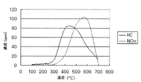
なお、図5は、ゼオライト系HC吸着触媒とカリウム系NOx吸着触媒の温度変化による脱着特性を示す図であり、これはHC吸着触媒とNOx吸着触媒に一定濃度のHCとNoxを吸着させた後温度を上げながら脱着されるHCとNoxの濃度を測定したものである。
図示するように、各吸着触媒はHC及びNoxを吸着した後(但し、吸着量は各吸着触媒の体積に依存する)、温度が上がりながら図5のグラフのように脱着し、少なくとも300℃以上ではHC及びNoxが徐々に脱着し始める。
本発明では、UCC触媒122,123がウォーミングアップしてから、中間パイプ114の内部流路114aが開いた状態でUCCの触媒122,123が十分な温度に上昇するまでCCC110内の各吸着触媒112,113からHC及びNoxが脱着されるのを遅延させる必要がある。
FIG. 5 is a diagram showing the desorption characteristics of the zeolite-based HC adsorption catalyst and the potassium-based NO x adsorption catalyst due to temperature changes, which adsorb a certain concentration of HC and No x on the HC adsorption catalyst and the NO x adsorption catalyst. Then , the concentration of HC and Nox desorbed was measured while raising the temperature.
As shown, after each adsorber which adsorbs HC and No x (where adsorption is dependent on the volume of each adsorption catalyst), and desorption as shown in the graph of FIG. 5 while rising the temperature is at least 300 ° C. in the above it begins to gradually desorbed HC and No x.
In the present invention, after the
このため、中間パイプ114の外周面と各吸着触媒112,113の中央ホール112a,113aの内周面との間にインシュレータ115を設けている。インシュレータ115は中間パイプ114の内部流路114aと吸着触媒112,113間の完全な断熱を図ると言うよりも、熱伝達を妨げる目的から設けるものであり、特定の断熱部材を設ける外に、中間パイプ114と吸着触媒112,113との間にエアギャップ(air gap)を設けることも可能である。
すなわち、UCC触媒122,123がウォーミングアップ状態に到達した後、初期にはUCC触媒がより高い温度状態になるまでCCC吸着触媒112,113におけるHC及びNoxの脱着を遅延させる必要があるが、インシュレータ115またはエアギャップは中間パイプの内部流路114aの排気ガス熱がHC及びNOx吸着触媒112,113に伝達されることをある程度妨げるため、吸着されていたHC及びNoxが熱によって自然脱着するのを時間的に遅延させる。
Therefore, an
That is, after the
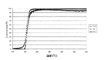
図6は一般のUCC触媒の温度増加による触媒の活性(浄化率)を示すものであり、200℃以下ですべての排気ガス浄化率が100%に近くなるため、ECUがUCC触媒のウォーミングアップ状態を判断する温度を基準に略200℃に設定すると本発明の達成が可能である。
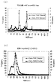
図7(a)及び図7(b)は、本発明の可変流路型排気ガス浄化システムと従来の‘CCC+UCC’方式の排気ガス浄化システムに関して250℃で浄化性能を評価した結果を示すものである。本発明の浄化システムでは初期始動モードから正常運転モードに流路を切り換えた後(ボールバルブ90°位置)、250℃で浄化性能を評価した。
本発明のシステムでは、従来のシステムに比べて初期始動モード(bag1)では1/5水準の排気ガスが排出され、全体的な評価結果ではSULEV基準値であるHC:0.01g/mile、NOx:0.02g/mileを満足した。
FIG. 6 shows the activity (purification rate) of the catalyst due to the temperature increase of a general UCC catalyst. Since all exhaust gas purification rates are close to 100% at 200 ° C. or lower, the ECU shows the warming-up state of the UCC catalyst. The present invention can be achieved when the temperature to be determined is set to approximately 200 ° C. with reference to the temperature to be determined.
7 (a) and 7 (b) show the results of evaluating the purification performance at 250 ° C. for the variable flow type exhaust gas purification system of the present invention and the conventional 'CCC + UCC' type exhaust gas purification system. is there. In the purification system of the present invention, after the flow path was switched from the initial start mode to the normal operation mode (ball valve 90 ° position), the purification performance was evaluated at 250 ° C.
In the system of the present invention, 1/5 level exhaust gas is discharged in the initial start mode (bag 1) as compared with the conventional system, and HC: 0.01 g / mile, NO which is the SULV reference value in the overall evaluation result. x : 0.02 g / mile was satisfied.
110:CCC
112:HC吸着触媒
113:NOx吸着触媒
114:中間パイプ
114b:羽根部
115:インシュレータ
120:UCC
130:温度感知センサ
140:ECU
150:流路切換手段
151:モータ
152:ボールバルブ
153:ガス流路
153a,153b:凹部
110: CCC
112: HC adsorption catalyst 113: NO x adsorption catalyst 114:
130: Temperature sensor 140: ECU
150: Channel switching means 151: Motor 152: Ball valve 153:
Claims (8)
ハウジング内部にHC吸着触媒とNOx吸着触媒が直列に内装されて排気経路上でエンジン排気マニフォールドの方に近く設けられ、排気ガスが前記2つの吸着触媒を介さずに直ちに排出されるようにするバイパス流路を有するCCCと;
該CCCの後方に車体フロアの下側の排気パイプの途中に設けられるUCCと;
前記UCC内の触媒の温度を検出するための温度感知センサと;
該温度感知センサの信号を入力され、既に設定された温度以上の場合、前記UCC内の触媒のウォーミングアップ状態であることを判断して前記CCC内の排気経路を前記バイパス流路に切り換えるための制御信号を出力するECUと;
該ECUの制御信号によって前記CCC内の吸着触媒側の流路とバイパス流路間の排気経路を切り換える流路切換手段と;
を含むことを特徴とする自動車排気ガス浄化システム。 An automobile exhaust gas purification system,
HC adsorbing catalyst and the NO x adsorption catalyst in the housing is provided close towards the engine exhaust manifold on the exhaust path are decorated in series, so that the exhaust gas is immediately discharged without passing through the two adsorption catalyst A CCC having a bypass flow path;
UCC provided in the middle of the exhaust pipe below the vehicle body floor behind the CCC;
A temperature sensing sensor for detecting the temperature of the catalyst in the UCC;
Control for switching the exhaust path in the CCC to the bypass flow path by judging that the catalyst in the UCC is in a warming-up state when the temperature sensor signal is input and the temperature is already set or higher. An ECU for outputting a signal;
Flow path switching means for switching an exhaust path between a flow path on the adsorption catalyst side in the CCC and a bypass flow path according to a control signal of the ECU;
An automobile exhaust gas purification system comprising:
Applications Claiming Priority (1)
| Application Number | Priority Date | Filing Date | Title |
|---|---|---|---|
| KR1020040023423A KR100590960B1 (en) | 2004-04-06 | 2004-04-06 | Automobile Exhaust Gas Purification System |
Publications (1)
| Publication Number | Publication Date |
|---|---|
| JP2005299631A true JP2005299631A (en) | 2005-10-27 |
Family
ID=35054501
Family Applications (1)
| Application Number | Title | Priority Date | Filing Date |
|---|---|---|---|
| JP2004307258A Pending JP2005299631A (en) | 2004-04-06 | 2004-10-21 | Automobile exhaust emission control system |
Country Status (4)
| Country | Link |
|---|---|
| US (1) | US20050220679A1 (en) |
| JP (1) | JP2005299631A (en) |
| KR (1) | KR100590960B1 (en) |
| CN (1) | CN1680693A (en) |
Cited By (3)
| Publication number | Priority date | Publication date | Assignee | Title |
|---|---|---|---|---|
| JP2008133743A (en) * | 2006-11-27 | 2008-06-12 | Toyota Motor Corp | Exhaust gas purification device for internal combustion engine |
| DE112008000975T5 (en) | 2007-04-13 | 2010-02-04 | Toyota Jidosha Kabushiki Kaisha, Toyota-shi | Exhaust gas purification device for internal combustion engine |
| US8261534B2 (en) | 2007-05-14 | 2012-09-11 | Toyota Jidosha Kabushiki Kaisha | Exhaust gas purifying apparatus for internal combustion engine |
Families Citing this family (35)
| Publication number | Priority date | Publication date | Assignee | Title |
|---|---|---|---|---|
| KR100734899B1 (en) | 2006-05-29 | 2007-07-03 | 한국기계연구원 | Post-treatment system and post-treatment method for diesel engine with HC adsorption catalyst |
| KR100844562B1 (en) * | 2006-12-13 | 2008-07-08 | 현대자동차주식회사 | Vehicle exhaust gas purification device and method |
| JP4501935B2 (en) * | 2006-12-28 | 2010-07-14 | トヨタ自動車株式会社 | Exhaust gas purification device for internal combustion engine |
| JP4710856B2 (en) * | 2007-03-15 | 2011-06-29 | トヨタ自動車株式会社 | Exhaust gas purification device for internal combustion engine |
| JP4321615B2 (en) * | 2007-03-28 | 2009-08-26 | トヨタ自動車株式会社 | INTERNAL COMBUSTION ENGINE DEVICE, ITS CONTROL METHOD, AND VEHICLE MOUNTED WITH INTERNAL COMBUSTION ENGINE DEVICE |
| KR100911587B1 (en) * | 2007-12-14 | 2009-08-10 | 현대자동차주식회사 | Variable flow path exhaust device and exhaust gas treatment method using the same |
| JP5157739B2 (en) * | 2008-08-11 | 2013-03-06 | 日産自動車株式会社 | Exhaust gas purification system and exhaust gas purification method using the same |
| JP5351476B2 (en) * | 2008-09-18 | 2013-11-27 | 富士フイルム株式会社 | Method for producing porous film |
| US9131535B2 (en) * | 2010-08-23 | 2015-09-08 | Toyota Jidosha Kabushiki Kaisha | Electric heating catalyst |
| DE102010056281A1 (en) | 2010-12-24 | 2012-06-28 | Volkswagen Ag | Exhaust system with HC adsorber and parallel catalytic converter and vehicle with such exhaust system |
| US20120204539A1 (en) * | 2011-02-10 | 2012-08-16 | GM Global Technology Operations LLC | Hybrid vehicle thermal management using a bypass path in a catalytic converter unit |
| US20120204536A1 (en) * | 2011-02-10 | 2012-08-16 | GM Global Technology Operations LLC | Catalytic converter combustion strategy for a hybrid vehicle |
| DE102011117090B4 (en) * | 2011-10-27 | 2023-01-26 | Volkswagen Aktiengesellschaft | emission control device |
| US8733084B2 (en) * | 2011-11-22 | 2014-05-27 | GM Global Technology Operations LLC | Bypass HC-NOx adsorber strategy |
| DE102014106386B4 (en) * | 2014-05-07 | 2016-08-11 | Benteler Automobiltechnik Gmbh | Exhaust gas heat exchanger with bypass pipe |
| CN105464759A (en) * | 2014-09-03 | 2016-04-06 | 葛洲坝能源重工有限公司 | Controllable tail gas denitration device |
| CN106894862B (en) * | 2015-12-18 | 2019-04-02 | 乔英电机有限公司 | Intelligent smoke exhaust improving device |
| EP3184767B1 (en) * | 2015-12-23 | 2019-07-03 | Volvo Car Corporation | Catalytic converter and exhaust-gas aftertreatment arrangement |
| CN105822890A (en) * | 2016-06-01 | 2016-08-03 | 吴本刚 | Purification circulating device of lubricating oil |
| CN105927328A (en) * | 2016-06-01 | 2016-09-07 | 吴本刚 | Filter for exhaust gas of diesel engine |
| CN105927329A (en) * | 2016-06-01 | 2016-09-07 | 吴本刚 | Catalytic conversion system for waste gas treatment |
| CN105927327A (en) * | 2016-06-01 | 2016-09-07 | 吴本刚 | High-temperature tail gas heat recovery energy-saving device |
| CN105927331A (en) * | 2016-06-01 | 2016-09-07 | 吴本刚 | Arched tunnel excavator |
| CN105952511A (en) * | 2016-06-01 | 2016-09-21 | 吴本刚 | Rectangular concrete grouting pile hole forming machine |
| CN105927332A (en) * | 2016-06-01 | 2016-09-07 | 吴本刚 | Novel marine exhaust gas treatment device |
| CN105927330A (en) * | 2016-06-01 | 2016-09-07 | 吴本刚 | Multi-shaft stirring pile drilling machine |
| CN106076110A (en) * | 2016-06-01 | 2016-11-09 | 吴本刚 | High-speed fermentation organic garbage disposal |
| CN106076026B (en) * | 2016-08-26 | 2017-12-15 | 赛洛克流体设备成都有限公司 | A kind of tapping equipment with the changeable bleed outlet of detection means |
| JP6935787B2 (en) * | 2018-08-23 | 2021-09-15 | トヨタ自動車株式会社 | Exhaust purification device and exhaust purification method for internal combustion engine |
| JP2020029841A (en) * | 2018-08-24 | 2020-02-27 | トヨタ自動車株式会社 | Exhaust gas purification device and exhaust gas purification method for internal combustion engine |
| KR102586451B1 (en) * | 2018-10-18 | 2023-10-06 | 현대자동차주식회사 | Variable valve for muffler and dual muffler including the same |
| DE102020119057B3 (en) * | 2020-07-20 | 2021-08-26 | Dr. Ing. H.C. F. Porsche Aktiengesellschaft | Exhaust tract for an internal combustion engine |
| CN113181971B (en) * | 2021-03-23 | 2024-07-12 | 渠晓东 | Catalyst carrier |
| CN113565606B (en) * | 2021-08-31 | 2022-09-16 | 易典军 | A three-way catalytic converter for automobile exhaust gas treatment |
| CN114837775B (en) * | 2022-04-01 | 2024-05-31 | 湖北丰盈节能环保科技股份有限公司 | An intelligently controlled energy-saving and emission-reduction device and method thereof |
Family Cites Families (9)
| Publication number | Priority date | Publication date | Assignee | Title |
|---|---|---|---|---|
| US5051244A (en) * | 1990-07-20 | 1991-09-24 | Uop | Use of a molecular sieve bed to minimize emissions during cold start of internal combustion engines |
| JP3083599B2 (en) * | 1991-09-30 | 2000-09-04 | 株式会社日立製作所 | Exhaust gas purification system |
| US5373696A (en) * | 1993-10-04 | 1994-12-20 | Ford Motor Company | Automotive engine with exhaust hydrocarbon adsorber having oxygen sensor regeneration control |
| DE4400202C1 (en) * | 1994-01-05 | 1995-04-06 | Daimler Benz Ag | Method for the reduction of hydrocarbon emissions from an internal combustion engine |
| EP0691459B1 (en) * | 1994-07-05 | 1998-11-11 | Ford Motor Company Limited | A catalyst system |
| US5766559A (en) * | 1997-02-03 | 1998-06-16 | General Motors Corporation | Exhaust gas management apparatus and method |
| JP3680244B2 (en) * | 1999-02-12 | 2005-08-10 | トヨタ自動車株式会社 | Adsorption amount calculation device for unburned fuel component adsorbent of internal combustion engine |
| US6167696B1 (en) * | 1999-06-04 | 2001-01-02 | Ford Motor Company | Exhaust gas purification system for low emission vehicle |
| US7117667B2 (en) * | 2002-07-11 | 2006-10-10 | Fleetguard, Inc. | NOx adsorber aftertreatment system for internal combustion engines |
-
2004
- 2004-04-06 KR KR1020040023423A patent/KR100590960B1/en not_active Expired - Fee Related
- 2004-10-21 JP JP2004307258A patent/JP2005299631A/en active Pending
- 2004-12-23 US US11/022,238 patent/US20050220679A1/en not_active Abandoned
- 2004-12-31 CN CNA2004101031836A patent/CN1680693A/en active Pending
Cited By (5)
| Publication number | Priority date | Publication date | Assignee | Title |
|---|---|---|---|---|
| JP2008133743A (en) * | 2006-11-27 | 2008-06-12 | Toyota Motor Corp | Exhaust gas purification device for internal combustion engine |
| DE112008000975T5 (en) | 2007-04-13 | 2010-02-04 | Toyota Jidosha Kabushiki Kaisha, Toyota-shi | Exhaust gas purification device for internal combustion engine |
| US8327622B2 (en) | 2007-04-13 | 2012-12-11 | Toyota Jidosha Kabushiki Kaisha | Exhaust gas purifying apparatus for internal combustion engine |
| DE112008000975B4 (en) * | 2007-04-13 | 2014-06-05 | Toyota Jidosha Kabushiki Kaisha | Exhaust gas purification device for internal combustion engine |
| US8261534B2 (en) | 2007-05-14 | 2012-09-11 | Toyota Jidosha Kabushiki Kaisha | Exhaust gas purifying apparatus for internal combustion engine |
Also Published As
| Publication number | Publication date |
|---|---|
| CN1680693A (en) | 2005-10-12 |
| KR20050098107A (en) | 2005-10-11 |
| US20050220679A1 (en) | 2005-10-06 |
| KR100590960B1 (en) | 2006-06-19 |
Similar Documents
| Publication | Publication Date | Title |
|---|---|---|
| JP2005299631A (en) | Automobile exhaust emission control system | |
| KR100413551B1 (en) | Exhaust purifying apparatus for internal combustion engine | |
| JP3546294B2 (en) | Exhaust gas purification device for internal combustion engine | |
| JP3395442B2 (en) | Switching valve device for exhaust gas | |
| JPH0763048A (en) | Exhaust emission control system and method thereof | |
| JP4408554B2 (en) | Exhaust gas recirculation system state determination device | |
| JP4456732B2 (en) | Device for detecting exhaust gas characteristics of an internal combustion engine | |
| JPH11343840A (en) | Exhaust gas purification device for internal combustion engine | |
| US6792749B2 (en) | Exhaust gas purifying apparatus for internal combustion engine | |
| US6945034B2 (en) | Exhaust gas purifying apparatus for internal combustion engine | |
| US6820416B2 (en) | Exhaust emission control system for an internal combustion engine | |
| JP3667559B2 (en) | Exhaust gas purification equipment for automobiles | |
| JP3587670B2 (en) | Exhaust gas purification equipment for automobiles | |
| KR100844562B1 (en) | Vehicle exhaust gas purification device and method | |
| JP2000073747A (en) | Catalyst system | |
| JP2010048112A (en) | Exhaust emission control system and exhaust emission control method | |
| JP3715134B2 (en) | Exhaust gas purification equipment for automobiles | |
| JP2008215277A (en) | Exhaust gas purification catalyst system | |
| JP3849183B2 (en) | Engine exhaust gas purification device | |
| JP4178379B2 (en) | Exhaust gas purification device for internal combustion engine | |
| JPH0771237A (en) | Exhaust gas purification device for internal combustion engine | |
| JP3774918B2 (en) | Exhaust gas purification equipment for automobiles | |
| JP4410976B2 (en) | Exhaust purification device | |
| JP3116627B2 (en) | Exhaust gas purification device | |
| JP3433461B2 (en) | Exhaust gas purification device |