JP3667559B2 - Exhaust gas purification equipment for automobiles - Google Patents
Exhaust gas purification equipment for automobiles Download PDFInfo
- Publication number
- JP3667559B2 JP3667559B2 JP14630999A JP14630999A JP3667559B2 JP 3667559 B2 JP3667559 B2 JP 3667559B2 JP 14630999 A JP14630999 A JP 14630999A JP 14630999 A JP14630999 A JP 14630999A JP 3667559 B2 JP3667559 B2 JP 3667559B2
- Authority
- JP
- Japan
- Prior art keywords
- exhaust gas
- adsorption
- catalyst
- partition wall
- gas purification
- Prior art date
- Legal status (The legal status is an assumption and is not a legal conclusion. Google has not performed a legal analysis and makes no representation as to the accuracy of the status listed.)
- Expired - Lifetime
Links
Images


Classifications
-
- Y—GENERAL TAGGING OF NEW TECHNOLOGICAL DEVELOPMENTS; GENERAL TAGGING OF CROSS-SECTIONAL TECHNOLOGIES SPANNING OVER SEVERAL SECTIONS OF THE IPC; TECHNICAL SUBJECTS COVERED BY FORMER USPC CROSS-REFERENCE ART COLLECTIONS [XRACs] AND DIGESTS
- Y02—TECHNOLOGIES OR APPLICATIONS FOR MITIGATION OR ADAPTATION AGAINST CLIMATE CHANGE
- Y02A—TECHNOLOGIES FOR ADAPTATION TO CLIMATE CHANGE
- Y02A50/00—TECHNOLOGIES FOR ADAPTATION TO CLIMATE CHANGE in human health protection, e.g. against extreme weather
- Y02A50/20—Air quality improvement or preservation, e.g. vehicle emission control or emission reduction by using catalytic converters
Description
【0001】
【技術分野】
本発明は,触媒部と吸着部とを用いて自動車の排ガスを浄化する,自動車用排ガス浄化装置に関する。
【0002】
【従来技術】
従来より,自動車の排ガス中に含まれるHC,CO,NOx等の有害成分を浄化するために,ハニカム構造体等の担体に,白金,ロジウム,パラジウム等の貴金属を担持した触媒装置が用いられている。
しかし,触媒装置が上記有害成分を浄化するためには,触媒装置温度が一定以上に達していなければならない。このため,エンジン始動直後の触媒装置温度が低いときには,上記有害成分を浄化できない。しかも,エンジン始動直後は,排出されるHC(以下コールドHCという)量が多く,このHCが浄化されないまま大気に放出される。
【0003】
この問題を解決すると共に,触媒活性,吸着性能を向上すべく,触媒装置と,その下流側に配置した吸着材とを有し,簡単かつ安価な構造で吸着材への有害成分の吸着及び脱離浄化を行なうことができる自動車用排ガス浄化装置が提案されている(特開平6−229223号公報)。
この装置では,暖気運転時には下流側の吸着材によりコールドHCを吸着しておき,エンジン暖気後は,上記吸着材に吸着させたコールドHCを離脱させて,コールドHCを触媒装置側へ戻して浄化を行なう。
【0004】
ところが,この自動車用排ガス浄化装置は,上記触媒装置と吸着材が別々に搭載されているため,小型化が困難であった。そこで,発明者は,外側部分に吸着部を有すると共に該吸着部よりも内側に触媒部を有するハニカム構造体からなる吸着触媒モジュールを有する,自動車用排ガス浄化装置を提案した。これにより,上記自動車用排ガス浄化装置の小型化を可能としている。
【0005】
【解決しようとする課題】
しかしながら,上記自動車用排ガス浄化装置においては,上記吸着部に流入した排ガスを上記触媒部へ折り返すために,上記ハニカム構造体の後端部に後端隔壁を周状に設ける必要がある。一方,該後端隔壁は通常金属製であるのに対し,上記ハニカム構造体はセラミック製である。そのため,両者は溶接することができず,また熱膨張率が異なるため,接合することが困難である。それ故,両者の間から排ガスが流出し,有害成分を含む排ガスが外部へ放出されるおそれがある。
【0006】
本発明は,かかる従来の問題点に鑑みてなされたもので,小型化が可能で,かつ有害成分の放出を確実に防止することができる自動車用排ガス浄化装置を提供しようとするものである。
【0007】
【課題の解決手段】
請求項1に記載の発明は,エンジンの排気管の途中に配設された吸着触媒モジュールを有する自動車用排ガス浄化装置であって,
上記吸着触媒モジュールは,ハウジング内に装着され,吸着材を担持したドーナツ状のハニカム構造体からなる吸着部と,
該吸着部の内側に管状隔壁を介して設けたメイン流路と,
該メイン流路に配設され,触媒を担持したハニカム構造体からなる触媒部とからなり,
かつ,上記管状隔壁には,上記触媒部の上流側において,上記吸着部と上記触媒部とを連通する開口部が設けられ,
また,上記管状隔壁における上記開口部の上流側には上記排ガスの上記触媒部への導入を制御するための切替手段が配設され,
上記吸着部が排ガス中の有害成分を吸着する吸着時には,上記排ガスが上記開口部を通じて上記吸着部から上記触媒部へ流入するよう構成してあり,
かつ上記開口部の上流側において,上記吸着部の内側側面と上記管状隔壁との間には,両者の間に支持部材が介設されて管状空洞部が設けられており,上記排ガスは上記吸着部及び上記管状空洞部を順次経由して上記メイン流路に流入するよう構成してあることを特徴とする自動車用排ガス浄化装置にある。
【0008】
本発明において最も注目すべきことは,上記吸着触媒モジュールは,ドーナツ状のハニカム構造体からなる吸着部と,該吸着部の内側に管状隔壁を介して設けたメイン流路と,該メイン流路に配設されたハニカム構造体からなる触媒部とからなることである。
なお,上記有害成分としては,例えば炭化水素(HC),一酸化炭素(CO),窒素酸化物(NOx)等がある。
また,上流側とは,排ガスの上記吸着触媒モジュールへの導入側をいい,下流側とは排出側をいう。
【0009】
本発明の自動車用排ガス浄化装置による排ガス浄化作用の一例につき説明する。
エンジン始動直後等上記触媒部が活性状態にないときには,上記吸着部が排ガス中の有害成分を吸着する。この吸着時には,エンジンから排出された上記排ガスを上記吸着部へ導入し,次いで上記開口部を通じて上記触媒部へ流入させる。
これにより,上記触媒部が活性状態になくとも,有害成分は上記吸着部に吸着され外部へ放出されない。
【0010】
一方,上記エンジンが暖気状態になり,触媒部が活性状態となった時には,上記エンジンから排出された排ガスの大部分を,上記メイン流路から上記触媒部へ直接導入し,該触媒部において上記有害成分を浄化する。
また,この時は上記吸着部へは有害成分を吸着させない。この非吸着時には,エンジンから排出された上記排ガスの一部を上記触媒部へも導入し,吸着部へ流入させる。これにより,上記吸着部に吸着されていた有害成分を離脱させ,該有害成分を上記触媒部において浄化する。
【0011】
次に,本発明の作用効果につき説明する。
上記吸着触媒モジュールは,上記のごとく,ドーナツ状のハニカム構造体からなる吸着部と,該吸着部の内側に管状隔壁を介して設けたメイン流路と,該メイン流路に設けた触媒部とからなる。
【0012】
即ち,上記管状隔壁は上記吸着部の内側側面に接合され,また,上記管状隔壁の内側側面に上記触媒部の外側側面を接合することにより,上記吸着触媒モジュールを構成している。そのため,上記吸着触媒モジュールにおいては,上記ハニカム構造体の端面における接合を行なう必要がない。
【0013】
それ故,上記吸着触媒モジュールは,接合困難な接合箇所も,不安定な接合箇所もなく構成される。これにより,排ガスは上述したような予定通りの流路を確実に通過するため,有害成分が外部へ放出するおそれがない。
また,上記吸着部と触媒部とは,上記管状隔壁を介して一体的に構成されるため,上記自動車用排ガス浄化装置を小型化することができる。
【0014】
以上のごとく,本発明によれば,小型化が可能で,かつ有害成分の放出を確実に防止することができる自動車用排ガス浄化装置を提供することができる。
【0015】
また,上記開口部の上流側において,上記吸着部の内側側面と上記管状隔壁との間には,両者の間に支持部材が介設されて管状空洞部が設けられており,上記排ガスは上記吸着部及び上記管状空洞部を順次経由して上記メイン流路に流入するよう構成してある。
これにより,上記吸着部を通過した排ガスの流路を,効率的に折り返すことが可能となり,上記自動車用排ガス浄化装置の一層の小型化を図ることができる。
なお,上記支持部材は,上記排ガスの洩れを防ぐシール部材としての役割をも有する。
【0016】
次に,請求項2に記載の発明のように,上記触媒部は,上記吸着部の後端部よりも下流側に設けられていることが好ましい。
これにより,上記吸着部を形成するドーナツ状の内側の直径を小さくすると共に,上記触媒部の直径を大きくすることができる。そのため,上記吸着触媒モジュールの直径を大きくすることなく,排ガスが通過する上記触媒部及び吸着部の断面積を大きくすることができる。それ故,上記自動車用排ガス浄化装置の浄化効率が向上する。
【0017】
次に,請求項3に記載の発明のように,上記開口部は,上記吸着部の後端部と上記触媒部の前端部との間における上記管状隔壁に設けられていることが好ましい。
これにより,上記吸着部の内側側面の全面を上記管状隔壁に接合することが可能である。そのため,上記吸着部と管状隔壁との接合を一層容易かつ確実に行なうことができる。
また,この場合には,上記吸着部を通過した排ガスが,折り返されることなく,そのまま上記触媒部へ流入するため,排ガス流れが一層円滑となる。
【0018】
次に,請求項4に記載の発明のように,上記切替手段は,上記吸着時には上記排ガスを上記吸着部に導入するよう切替え,非吸着時には主に触媒部へ導入するよう切替えるアクチュエータを有していることが好ましい。
これにより,上記排ガス流路の切替を確実に行なうことが可能となる。
【0019】
次に,請求項5に記載の発明のように,上記支持部材は吸着材を担持していることが好ましい。
これにより,上記吸着部を通過する前の排ガスが,上記支持部材の部分から洩れた場合にも,上記支持部材に担持された吸着材によって有害成分を吸着することができる。そのため,有害成分の放出を一層確実に防止することができる自動車用排ガス浄化装置を得ることができる。
【0020】
次に,請求項6に記載の発明のように,上記支持部材は,所定の間隔をもって複数本配設してあり,該複数本の支持部材と上記吸着部と上記管状隔壁とにより形成される空間には,吸着材を充填してあることが好ましい。
これにより,上記吸着部を通過する前の排ガスが,上記支持部材の部分から洩れた場合にも,上記空間に充填された吸着材によって有害成分を吸着することができる。そのため,有害成分の放出を一層確実に防止することができる自動車用排ガス浄化装置を得ることができる。
【0021】
【発明の実施の形態】
実施形態例1
本発明の実施形態例にかかる自動車用排ガス浄化装置につき,図1〜図6を用いて説明する。
本例の自動車用排ガス浄化装置1は,図2に示すごとく,エンジン7の排気管72の途中に配設された吸着触媒モジュール10を有する。
【0022】
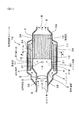
上記吸着触媒モジュール10は,図1に示すごとく,ハウジング2内に装着され,吸着材を担持したドーナツ状のハニカム構造体からなる吸着部11を有する。該吸着部11の内側には,管状隔壁3を介して設けたメイン流路30が形成されている。該メイン流路30の下流側(図1の右方側)には,触媒を担持したハニカム構造体からなる触媒部12が配設してある。
【0023】
そして,上記管状隔壁3には,上記触媒部12の上流側(図1の左方側)において,上記吸着部11と上記触媒部12とを連通する開口部31が設けられている。
また,上記管状隔壁3における上記開口部31の上流側には上記排ガス8の上記触媒部12への導入を制御するための切替手段5が配設されている。
上記自動車用排ガス浄化装置1は,上記吸着部11が排ガス8中のコールドHC等の有害成分を吸着する吸着時には,上記排ガス8が上記開口部31を通じて上記吸着部11から上記触媒部12へ流入するよう構成してある。
なお,上記切替手段5の上流側における上記管状隔壁3には,貫通穴32が設けてある。
【0024】
上記吸着部11と上記管状隔壁3との間には,両者の間に介設した支持部材4により形成された管状空洞部13が設けられている。上記排ガス8は,図1の破線矢印に示すように,上記吸着部11,管状空洞部13を経由して上記メイン流路30に流入する。
【0025】
図1,図4に示すごとく,上記吸着部11の外側側面は,保持部材24を介して上記ハウジング2の内側側面に接合されている。上記吸着部11の内側側面114には,上記支持部材4を介して上記管状隔壁3が配設されている。そして,上記管状隔壁3の内側側面には,保持部材34を介して上記触媒部12の外側側面が接合されている。
【0026】
図2に示すごとく,上記自動車用排ガス浄化装置1は,エンジン7の下流の排気管72の途中に設けられたスタート触媒14と上記吸着触媒モジュール10,及び切替制御装置50とからなる。
上記スタート触媒14は,エンジン始動時における排ガスの浄化に用いられる,ハニカム構造体に触媒を担持してなる触媒装置である。また,上記切替制御装置50は,下記に示す切替手段5の切替を行なうアクチュエータ53を制御する装置である。
【0027】
上記切替手段5は,上記吸着時には上記排ガス8を上記吸着部11に導入するよう切替え,非吸着時には主に触媒部12へ導入するよう切替えるアクチュエータ53を有している(図2)。
また,上記切替手段5は,図3に示すごとく,上記管状隔壁3に回動可能に取付けられた回動軸58と,該回動軸58に固定され,上記管状隔壁3の内周形状と略同形状の開閉弁59とからなる。
図3において,実線で示した開閉弁59は閉止時の状態を表し,二点鎖線で示した開閉弁59は開放時の状態を表す。
【0028】
上記支持部材4は,図5(A)に示すごとく,上記開口部31の上流側において,上記吸着部11と上記管状隔壁13との間に設けてある。そして,上記支持部材4は吸着材を担持している。
なお,上記支持部材4は,図5(B)に示すごとく,所定の間隔をもって2本配設し,該2本の支持部材4と上記吸着部11と上記管状隔壁13とにより形成される空間に,吸着材41を充填してもよい。
【0029】
次に,上記切替制御装置50による上記切替手段5の切替につき,図6を用いて説明する。
まず,ステップS1として,エンジン始動時にコントローラ52(図2)のタイマーがリセットされる。次に,ステップS2において,エンジン7の水温Twと設定温度Tw0とを比較する。Tw>Tw0の場合には,触媒部12の触媒が活性状態にあると判断し,切替手段5を開放して,大部分の排ガス8を上記触媒部12に導入する(図1の実線矢印)。
【0030】
一方,Tw≦Tw0の場合には,触媒部12の触媒が未活性状態にあると判断し,切替手段5を閉止して,排ガス8の全量を上記貫通穴32を通じて上記吸着部11に導入する(ステップS3)。
これにより,排ガス8は上記吸着部11を通過し,上記管状空洞部13に折り返される。そして,上記排ガス8は,上記管状空洞部13から上記開口部31を通じてメイン流路30に流入し,上記触媒部12を通過する(図1の破線矢印)。
【0031】
この時,上記コントローラ52のタイマーはエンジン始動(S1)からの時間をカウントしており,その時間tと所定時間t0とを比較する(ステップS4)。
次に,t≧t0となったとき,上記スタート触媒14の温度が上昇して触媒が活性状態となったと判断して,上記切替手段5を開放する(ステップS5)。
これにより,排ガス8を上記触媒部12に直接導入して通過させる(図1の実線矢印)。また,この時,排ガス8の一部は上記吸着部11に導入される。更にこの状態で数秒〜数十秒運転することにより,上記触媒部12が活性化する。
【0032】
なお,切替手段5の切替は,以下のように行なう。
即ち,上記アクチュエータ53は,配管55によって,電磁弁54を介して上記エンジン7の吸気部71と接続されている。上記吸気部71は,エンジン作動時には常に負圧となっている。上記コントローラ52の信号により,上記電磁弁54が開閉することにより,その負圧が上記アクチュエータ53に作用し上記切替手段5を開閉する。
【0033】
次に,本例の自動車用排ガス浄化装置1による排ガス浄化作用につき説明する。
上記スタート触媒14はエンジン7の直後に配置してあるため,エンジン始動から比較的短時間で活性状態となる。しかし,エンジン始動直後等,エンジン7自体の温度が低いときには,上記スタート触媒14が未活性状態にある。
【0034】
そこで,上述のごとく,エンジン7の水温を確認して,これが設定値よりも低いときには,上記スタート触媒14も未活性であると判断する。そして,エンジン7から排出され上記スタート触媒14を通過した上記排ガス8を上記吸着部11へ導入し,次いで上記触媒部12へ流入させる(図1の破線矢印)。
これにより,上記触媒部12及びスタート触媒14が活性状態になくとも,コールドHC,CO,NOx等の有害成分は,上記吸着部11に吸着され外部へ放出されない。
【0035】
一方,上記エンジン7が暖気状態になり,スタート触媒14が活性状態となった時には,上記エンジン7から排出され,スタート触媒14を通過した排ガス8の大部分を,上記触媒部12へ直接導入する。この状態で数秒〜数十秒運転すると,上記触媒部12が活性化し,該触媒部12においてヒートHC等の上記有害成分が浄化される(図1の実線矢印)。
【0036】
また,この時はエンジン7から排出された上記排ガス8の一部を,上記吸着部11を経て,触媒部12へ流入させる。これにより,上記吸着部11に吸着されていたコールドHC等の有害成分を排ガス8中へ離脱させ,該有害成分を上記触媒部12において浄化する。
即ち,この状態では,有害成分を上記吸着部11へ吸着させない,非吸着時となる。
【0037】
次に,本例の作用効果につき説明する。
上記吸着触媒モジュール10は,上記のごとく,ドーナツ状のハニカム構造体からなる吸着部11と,該吸着部11の内側に管状隔壁3を介して設けたメイン流路30と,該メイン流路30の下流側に設けた触媒部12とからなる(図1)。
【0038】
即ち,上記吸着触媒モジュール10は,上記管状隔壁3を上記吸着部11の内側側面114に上記支持部材4を介して配設し,また,上記管状隔壁3の内側側面に上記触媒部12の外側側面を保持部材34を介して接合することにより構成されている。そのため,上記吸着触媒モジュール10においては,上記ハニカム構造体の端面における接合を行なう必要がない。
【0039】
それ故,上記吸着触媒モジュール10は,接合困難な接合箇所も,不安定な接合箇所もなく構成される。これにより,排ガス8は上述したような予定通りの流路を確実に通過するため,有害成分が外部へ放出されるおそれがない。
また,上記吸着部11と触媒部12とは,上記管状隔壁3を介して一体的に構成されるため,上記自動車用排ガス浄化装置1を小型化することができる。
【0040】
また,上記吸着部11と上記管状隔壁3との間には,上記管状空洞部13が設けられている。
そのため,上記吸着部11を通過した排ガス8の流路を,効率的に折り返すことが可能となり,上記自動車用排ガス浄化装置1の一層の小型化を図ることができる。
【0041】
また,上記切替手段5は,上記吸着時と非吸着時における,上記排ガス8の上記吸着部11への導入を切替えるアクチュエータ53を有している。
そのため,上記排ガス流路の切替を確実に行なうことが可能となる。
【0042】
また,上記支持部材4は吸着材を担持しているため,上記吸着部11を通過する前の排ガス8が,上記支持部材4の部分から洩れた場合にも,上記支持部材4に担持された吸着材によって有害成分を吸着することができる。そのため,有害成分の放出を一層確実に防止することができる。
即ち,上記貫通穴32から導入された排ガス8が,上記吸着部11を通過する前に,上記支持部材4から上記管状空洞部14へ直接流入した場合にも,有害成分は上記支持部材4に担持された吸着材により吸着される。
【0043】
以上のごとく,本例によれば,小型化が可能で,かつ有害成分の放出を確実に防止することができる自動車用排ガス浄化装置を提供することができる。
【0044】
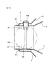
実施形態例2
本例は,図7,図8に示すごとく,触媒部12が,吸着部11の後端部119よりも下流側に設けられている吸着触媒モジュール10を有する自動車用排ガス浄化装置の例である。
即ち,上記触媒部12の前端部121は,上記吸着部11の後端部119よりも下流側に配置されている(図7)。
【0045】
上記吸着触媒モジュール10のメイン流路30は,図7に示すごとく,上記吸着部11を形成するドーナツ状の内側における小径部301と,その下流側における大径部302とからなる。該大径部302には,上記触媒部12が設けられている。
その他は,実施形態例1と同様である。
【0046】
上記触媒部12は,上記メイン流路30の大径部302に設けてあるため,上記触媒部12の断面積を大きくすることができる(図7)。一方,上記吸着部11は,上記メイン流路30の小径部301の外側にドーナツ状に設けてあるため,図8に示すごとく,上記吸着部11の断面積も大きくすることができる。
【0047】
それ故,上記吸着触媒モジュール10の直径を大きくすることなく,排ガス8が通過する上記吸着部11及び触媒部12の断面積を大きくすることができる。これにより,上記吸着部11の吸着機能及び触媒部12の触媒機能が充分に発揮される。
従って,本例によれば,一層排ガスの浄化効率が高い自動車用排ガス浄化装置を得ることができる。
その他,実施形態例1と同様の作用効果を有する。
【0048】
実施形態例3
本例は,図9に示すごとく,上記開口部31を,上記吸着部11の後端部119と上記触媒部12の前端部121との間における上記管状隔壁3に設けた,吸着触媒モジュール10を有する自動車排ガス浄化装置の例である。
そして,上記メイン流路30の小径部301の管状隔壁3の外側に,上記吸着部11の内側側面114の全面を,支持部材40を介して接合してある。即ち,上記支持部材40は,上記吸着部材11の内側側面114の略全面に接合してある(図9)。
その他は,実施形態例2と同様である。
【0049】
上記吸着部11は,その内側側面114の全面を管状隔壁3の外側に,支持部材40を介して接合してある。そのため,上記吸着部11と管状隔壁3との接合を一層容易かつ確実に行なうことができる。
また,上記吸着部11の後端部119と上記触媒部12の前端部121との間に,上記開口部31が設けられているため,上記吸着部11を通過した排ガスが,折り返すことなく,そのまま上記触媒部12へ流入する。そのため,排ガス8の流れが一層円滑となる。
その他,実施形態例2と同様の作用効果を有する。
【0050】
なお,図7〜図9においては,上記実施形態例2又は実施形態例3において言及しなかった部分については,実施形態例1と同様の符号を用いた。
【図面の簡単な説明】
【図1】実施形態例1における,自動車用排ガス浄化装置の吸着触媒モジュールの断面説明図。
【図2】実施形態例1における,自動車用排ガス浄化装置の説明図。
【図3】実施形態例1における,切替手段の断面説明図。
【図4】図1のA−A線矢視断面図。
【図5】実施形態例1おける,(A)支持部材の配設方法,及び(B)支持部材の他の配設方法の説明図。
【図6】実施形態例1における,切替制御装置による切替手段の制御方法を示すフローチャート。
【図7】実施形態例2における,自動車用排ガス浄化装置の吸着触媒モジュールの断面説明図。
【図8】図7のB−B線矢視断面図。
【図9】実施形態例3における,自動車用排ガス浄化装置の吸着触媒モジュールの断面説明図。
【符号の説明】
1...自動車用排ガス浄化装置,
10...吸着触媒モジュール,
11...吸着部,
12...触媒部,
13...管状空洞部,
2...ハウジング,
3...管状隔壁,
30...メイン流路,
31...開口部,
4,40...支持部材,
5...切替手段,
8...排ガス,[0001]
【Technical field】
The present invention relates to an automobile exhaust gas purification device that purifies automobile exhaust gas using a catalyst part and an adsorption part.
[0002]
[Prior art]
Conventionally, in order to purify harmful components such as HC, CO, NOx, etc. contained in the exhaust gas of an automobile, a catalyst device in which a noble metal such as platinum, rhodium, palladium is supported on a carrier such as a honeycomb structure has been used. Yes.
However, in order for the catalyst device to purify the harmful components, the temperature of the catalyst device must reach a certain level. For this reason, when the temperature of the catalytic device immediately after engine startup is low, the harmful components cannot be purified. Moreover, immediately after the engine is started, the amount of discharged HC (hereinafter referred to as cold HC) is large, and this HC is released to the atmosphere without being purified.
[0003]
In order to solve this problem and improve the catalytic activity and adsorption performance, it has a catalytic device and an adsorbent disposed downstream thereof, and adsorbs and desorbs harmful components on the adsorbent with a simple and inexpensive structure. An automobile exhaust gas purification device capable of performing separation and purification has been proposed (Japanese Patent Laid-Open No. 6-229223).
In this device, the cold HC is adsorbed by the downstream adsorbent during warm-up operation, and after the engine warms up, the cold HC adsorbed on the adsorbent is removed, and the cold HC is returned to the catalyst device side for purification. To do.
[0004]
However, it is difficult to reduce the size of this automobile exhaust gas purification device because the catalyst device and the adsorbent are mounted separately. In view of this, the inventor has proposed an automobile exhaust gas purification apparatus having an adsorption catalyst module made of a honeycomb structure having an adsorption portion at the outer portion and a catalyst portion inside the adsorption portion. As a result, the automobile exhaust gas purification device can be miniaturized.
[0005]
[Problems to be solved]
However, in the exhaust gas purifying apparatus for automobiles, in order to return the exhaust gas flowing into the adsorption part to the catalyst part, it is necessary to provide a rear end partition wall at the rear end part of the honeycomb structure. On the other hand, the rear end partition walls are usually made of metal, whereas the honeycomb structure is made of ceramic. For this reason, both cannot be welded, and the coefficients of thermal expansion are different, making them difficult to join. Therefore, there is a risk that exhaust gas flows out from between the two and exhaust gas containing harmful components is released to the outside.
[0006]
The present invention has been made in view of such conventional problems, and an object of the present invention is to provide an automobile exhaust gas purification device that can be miniaturized and can reliably prevent the release of harmful components.
[0007]
[Means for solving problems]
The invention according to
The adsorption catalyst module is mounted in a housing and has an adsorption part made of a donut-shaped honeycomb structure carrying an adsorbent,
A main channel provided inside the adsorbing part via a tubular partition;
A catalyst portion that is disposed in the main flow path and includes a honeycomb structure carrying a catalyst;
The tubular partition wall is provided with an opening communicating with the adsorbing portion and the catalyst portion on the upstream side of the catalyst portion,
Further, switching means for controlling the introduction of the exhaust gas into the catalyst part is disposed upstream of the opening in the tubular partition wall,
During adsorption the adsorption section adsorbs harmful components in the exhaust gas, Ri tear the exhaust gas is arranged to flow from the suction unit through the opening into the catalyst unit,
Further, on the upstream side of the opening, a tubular cavity is provided between the inner side surface of the adsorption part and the tubular partition wall with a support member interposed therebetween, and the exhaust gas is adsorbed on the adsorption part. The exhaust gas purifying apparatus for automobiles is configured to flow into the main flow path sequentially through the section and the tubular cavity .
[0008]
The most notable aspect of the present invention is that the adsorption catalyst module includes an adsorption portion made of a donut-shaped honeycomb structure, a main flow path provided inside the adsorption portion via a tubular partition wall, and the main flow path. And a catalyst portion made of a honeycomb structure.
Examples of the harmful component include hydrocarbon (HC), carbon monoxide (CO), nitrogen oxide (NOx), and the like.
The upstream side refers to the side where the exhaust gas is introduced into the adsorption catalyst module, and the downstream side refers to the discharge side.
[0009]
An example of the exhaust gas purification action by the automobile exhaust gas purification apparatus of the present invention will be described.
When the catalyst part is not in an active state, such as immediately after the engine is started, the adsorbing part adsorbs harmful components in the exhaust gas. At the time of this adsorption, the exhaust gas discharged from the engine is introduced into the adsorption part, and then flows into the catalyst part through the opening.
Thereby, even if the catalyst part is not in an active state, harmful components are adsorbed by the adsorption part and are not released to the outside.
[0010]
On the other hand, when the engine is warmed up and the catalyst part is activated, most of the exhaust gas discharged from the engine is directly introduced into the catalyst part from the main flow path. Purifies harmful ingredients.
At this time, no harmful components are adsorbed on the adsorbing portion. At the time of non-adsorption, a part of the exhaust gas discharged from the engine is also introduced into the catalyst part and flows into the adsorption part. As a result, the harmful components adsorbed on the adsorbing portion are separated, and the harmful components are purified in the catalyst portion.
[0011]
Next, the effects of the present invention will be described.
As described above, the adsorption catalyst module includes an adsorption part made of a doughnut-shaped honeycomb structure, a main channel provided inside the adsorption part via a tubular partition, a catalyst unit provided in the main channel, Consists of.
[0012]
That is, the tubular partition wall is joined to the inner side surface of the adsorption part, and the outer side surface of the catalyst part is joined to the inner side surface of the tubular partition wall to constitute the adsorption catalyst module. Therefore, in the adsorption catalyst module, it is not necessary to perform bonding at the end face of the honeycomb structure.
[0013]
Therefore, the adsorption catalyst module is configured with neither a difficult-to-join joint nor an unstable joint. As a result, the exhaust gas reliably passes through the planned flow path as described above, and there is no possibility that harmful components are released to the outside.
Moreover, since the said adsorption part and a catalyst part are comprised integrally through the said tubular partition, the said exhaust gas purification apparatus for motor vehicles can be reduced in size.
[0014]
As described above, according to the present invention, it is possible to provide an automobile exhaust gas purification device that can be miniaturized and can reliably prevent the release of harmful components.
[0015]
Further, at the upstream side of the opening, between the inner side surface and the tubular partition wall of the suction unit, supporting support member is interposed tubular hollow portion is provided between the two, the exhaust gas via the upper Symbol adsorption portion and the tubular hollow portion successively it is configured to flow into the main flow path.
As a result, the exhaust gas flow path that has passed through the adsorption section can be efficiently folded back, and the automobile exhaust gas purification device can be further miniaturized.
The support member also serves as a seal member that prevents the exhaust gas from leaking.
[0016]
Next, as in the invention described in
As a result, the inner diameter of the donut forming the adsorbing portion can be reduced and the diameter of the catalyst portion can be increased. Therefore, the cross-sectional areas of the catalyst part and the adsorption part through which the exhaust gas passes can be increased without increasing the diameter of the adsorption catalyst module. Therefore, the purification efficiency of the exhaust gas purification apparatus for automobiles is improved.
[0017]
Next, as in the invention described in
Thereby, it is possible to join the whole inner side surface of the adsorption part to the tubular partition wall. Therefore, the adsorbing part and the tubular partition can be joined more easily and reliably.
Further, in this case, the exhaust gas that has passed through the adsorption part flows into the catalyst part as it is without being folded back, so that the exhaust gas flow becomes smoother.
[0018]
Next, as in a fourth aspect of the present invention, the switching means includes an actuator that switches to introduce the exhaust gas into the adsorption unit during the adsorption, and mainly switches to the catalyst unit during non-adsorption. It is preferable.
This makes it possible to reliably switch the exhaust gas flow path.
[0019]
Next, as in the invention described in
Thereby, even when the exhaust gas before passing through the adsorption part leaks from the part of the support member, harmful components can be adsorbed by the adsorbent carried on the support member. Therefore, it is possible to obtain an automobile exhaust gas purification device that can more reliably prevent the release of harmful components.
[0020]
Next, as in a sixth aspect of the present invention, a plurality of the support members are arranged at a predetermined interval, and are formed by the plurality of support members, the adsorption portion, and the tubular partition wall. The space is preferably filled with an adsorbent.
Thereby, even when the exhaust gas before passing through the adsorbing portion leaks from the portion of the support member, harmful components can be adsorbed by the adsorbent filled in the space. Therefore, it is possible to obtain an automobile exhaust gas purification device that can more reliably prevent the release of harmful components.
[0021]
DETAILED DESCRIPTION OF THE INVENTION
An automobile exhaust gas purifying apparatus according to an embodiment of the present invention will be described with reference to FIGS.
As shown in FIG. 2, the automobile exhaust
[0022]
As shown in FIG. 1, the
[0023]
The
Further, a switching means 5 for controlling the introduction of the
In the exhaust
The
[0024]
Between the
[0025]
As shown in FIGS. 1 and 4, the outer side surface of the
[0026]
As shown in FIG. 2, the automobile exhaust
The
[0027]
The switching means 5 has an
Further, as shown in FIG. 3, the switching means 5 includes a
In FIG. 3, the open /
[0028]
As shown in FIG. 5A, the
As shown in FIG. 5B, two
[0029]
Next, switching of the switching means 5 by the switching
First, as step S1, the timer of the controller 52 (FIG. 2) is reset when the engine is started. Next, in step S2, compares the water temperature Tw of the engine 7 and the set temperature Tw 0. In the case of Tw> Tw 0 is the catalyst of the
[0030]
On the other hand, in the case of Tw ≦ Tw 0 is the catalyst of the
As a result, the
[0031]
In this case, the timer of the
Next, when t ≧ t 0 , it is determined that the temperature of the
As a result, the
[0032]
The switching of the switching means 5 is performed as follows.
That is, the
[0033]
Next, the exhaust gas purification action of the automobile exhaust
Since the
[0034]
Therefore, as described above, the water temperature of the engine 7 is confirmed, and if it is lower than the set value, it is determined that the
Thereby, even if the
[0035]
On the other hand, when the engine 7 is warmed up and the
[0036]
At this time, a part of the
That is, in this state, the harmful component is not adsorbed to the adsorbing
[0037]
Next, the effect of this example will be described.
As described above, the
[0038]
That is, the
[0039]
Therefore, the
Moreover, since the said
[0040]
Further, the
Therefore, the flow path of the
[0041]
The switching means 5 has an
Therefore, it is possible to reliably switch the exhaust gas flow path.
[0042]
Further, since the
That is, even when the
[0043]
As described above, according to this example, it is possible to provide an automobile exhaust gas purification device that can be downsized and can reliably prevent the release of harmful components.
[0044]
This example is an example of an automobile exhaust gas purification apparatus in which the
In other words, the
[0045]
As shown in FIG. 7, the
Others are the same as in the first embodiment.
[0046]
Since the
[0047]
Therefore, the cross-sectional areas of the
Therefore, according to this example, it is possible to obtain an automobile exhaust gas purification device with higher exhaust gas purification efficiency.
In addition, it has the same effects as the first embodiment.
[0048]
In this example, as shown in FIG. 9, the
The entire
Others are the same as the second embodiment.
[0049]
The
In addition, since the
In addition, it has the same operational effects as the second embodiment.
[0050]
7 to 9, the same reference numerals as those in the first embodiment are used for portions not mentioned in the second embodiment or the third embodiment.
[Brief description of the drawings]
BRIEF DESCRIPTION OF DRAWINGS FIG. 1 is a cross-sectional explanatory view of an adsorption catalyst module of an automobile exhaust gas purification apparatus in
FIG. 2 is an explanatory diagram of an automobile exhaust gas purification apparatus in
FIG. 3 is a cross-sectional explanatory view of switching means in
4 is a cross-sectional view taken along line AA in FIG.
FIGS. 5A and 5B are explanatory views of (A) a method for arranging a support member and (B) another method for arranging a support member in
6 is a flowchart showing a method for controlling switching means by the switching control device in
7 is a cross-sectional explanatory view of an adsorption catalyst module of an automobile exhaust gas purification apparatus in
8 is a cross-sectional view taken along line BB in FIG.
9 is a cross-sectional explanatory view of an adsorption catalyst module of an automobile exhaust gas purification apparatus in
[Explanation of symbols]
1. . . Exhaust gas purification equipment for automobiles,
10. . . Adsorption catalyst module,
11. . . Adsorption part,
12 . . Catalyst part,
13. . . Tubular cavity,
2. . . housing,
3. . . Tubular septum,
30. . . Main flow path,
31. . . Aperture,
4,40. . . Support member,
5. . . Switching means,
8). . . Exhaust gas,
Claims (6)
上記吸着触媒モジュールは,ハウジング内に装着され,吸着材を担持したドーナツ状のハニカム構造体からなる吸着部と,
該吸着部の内側に管状隔壁を介して設けたメイン流路と,
該メイン流路に配設され,触媒を担持したハニカム構造体からなる触媒部とからなり,
かつ,上記管状隔壁には,上記触媒部の上流側において,上記吸着部と上記触媒部とを連通する開口部が設けられ,
また,上記管状隔壁における上記開口部の上流側には上記排ガスの上記触媒部への導入を制御するための切替手段が配設され,
上記吸着部が排ガス中の有害成分を吸着する吸着時には,上記排ガスが上記開口部を通じて上記吸着部から上記触媒部へ流入するよう構成してあり,
かつ上記開口部の上流側において,上記吸着部の内側側面と上記管状隔壁との間には,両者の間に支持部材が介設されて管状空洞部が設けられており,上記排ガスは上記吸着部及び上記管状空洞部を順次経由して上記メイン流路に流入するよう構成してあることを特徴とする自動車用排ガス浄化装置。An automobile exhaust gas purification device having an adsorption catalyst module disposed in the middle of an engine exhaust pipe,
The adsorption catalyst module is mounted in a housing and has an adsorption part made of a donut-shaped honeycomb structure carrying an adsorbent,
A main channel provided inside the adsorbing part via a tubular partition;
A catalyst portion that is disposed in the main flow path and includes a honeycomb structure carrying a catalyst;
The tubular partition wall is provided with an opening communicating with the adsorbing portion and the catalyst portion on the upstream side of the catalyst portion,
Further, switching means for controlling the introduction of the exhaust gas into the catalyst part is disposed upstream of the opening in the tubular partition wall,
During adsorption the adsorption section adsorbs harmful components in the exhaust gas, Ri tear the exhaust gas is arranged to flow from the suction unit through the opening into the catalyst unit,
Further, on the upstream side of the opening, a tubular cavity is provided between the inner side surface of the adsorption part and the tubular partition wall with a support member interposed therebetween, and the exhaust gas is adsorbed on the adsorption part. An exhaust gas purifying apparatus for an automobile, wherein the exhaust gas purifying apparatus for an automobile is configured to flow into the main flow path sequentially through a portion and the tubular hollow portion .
Priority Applications (1)
| Application Number | Priority Date | Filing Date | Title |
|---|---|---|---|
| JP14630999A JP3667559B2 (en) | 1999-05-26 | 1999-05-26 | Exhaust gas purification equipment for automobiles |
Applications Claiming Priority (1)
| Application Number | Priority Date | Filing Date | Title |
|---|---|---|---|
| JP14630999A JP3667559B2 (en) | 1999-05-26 | 1999-05-26 | Exhaust gas purification equipment for automobiles |
Publications (2)
| Publication Number | Publication Date |
|---|---|
| JP2000337135A JP2000337135A (en) | 2000-12-05 |
| JP3667559B2 true JP3667559B2 (en) | 2005-07-06 |
Family
ID=15404771
Family Applications (1)
| Application Number | Title | Priority Date | Filing Date |
|---|---|---|---|
| JP14630999A Expired - Lifetime JP3667559B2 (en) | 1999-05-26 | 1999-05-26 | Exhaust gas purification equipment for automobiles |
Country Status (1)
| Country | Link |
|---|---|
| JP (1) | JP3667559B2 (en) |
Families Citing this family (7)
| Publication number | Priority date | Publication date | Assignee | Title |
|---|---|---|---|---|
| JP4534860B2 (en) * | 2004-12-15 | 2010-09-01 | トヨタ自動車株式会社 | Engine exhaust purification device and method of manufacturing the same |
| US20110296820A1 (en) * | 2010-06-02 | 2011-12-08 | Gm Global Technology Operations, Inc. | Engine exhaust gas treatment device including electrically actuated hydrocarbon adsorber bypass valve |
| DE102010056281A1 (en) | 2010-12-24 | 2012-06-28 | Volkswagen Ag | Exhaust system with HC adsorber and parallel catalytic converter and vehicle with such exhaust system |
| DE102011101982A1 (en) * | 2011-05-19 | 2012-11-22 | Volkswagen Aktiengesellschaft | Exhaust system with HC adsorber and parallel catalytic converter and vehicle with such exhaust system |
| DE102011117090B4 (en) | 2011-10-27 | 2023-01-26 | Volkswagen Aktiengesellschaft | emission control device |
| JP5825726B2 (en) * | 2014-04-10 | 2015-12-02 | ヤンマー株式会社 | Exhaust gas purification device |
| US11512621B2 (en) * | 2018-10-09 | 2022-11-29 | Volvo Truck Corporation | Exhaust aftertreatment arrangement for an exhaust system of an internal combustion engine |
-
1999
- 1999-05-26 JP JP14630999A patent/JP3667559B2/en not_active Expired - Lifetime
Also Published As
| Publication number | Publication date |
|---|---|
| JP2000337135A (en) | 2000-12-05 |
Similar Documents
| Publication | Publication Date | Title |
|---|---|---|
| JP2005299631A (en) | Automobile exhaust emission control system | |
| JP2000018026A (en) | Exhaust emission control device for internal combustion engine | |
| JPH11210451A (en) | Exhaust emission control catalyst device of internal combustion engine | |
| JP3667559B2 (en) | Exhaust gas purification equipment for automobiles | |
| JPH0814034A (en) | Exhaust emission control device | |
| JPH11343840A (en) | Exhaust emission control device for internal combustion engine | |
| JP3715134B2 (en) | Exhaust gas purification equipment for automobiles | |
| JP3587670B2 (en) | Exhaust gas purification equipment for automobiles | |
| JP2000073747A (en) | Catalyst system | |
| JP3456008B2 (en) | Exhaust gas purification device for internal combustion engine | |
| JP3178142B2 (en) | Exhaust gas purification device | |
| JPH0771237A (en) | Exhaust emission control device for internal combustion engine | |
| JP3116627B2 (en) | Exhaust gas purification device | |
| JPH06241028A (en) | Exhaust gas purifier | |
| JP3774918B2 (en) | Exhaust gas purification equipment for automobiles | |
| JP3343948B2 (en) | Exhaust gas purification device | |
| JP3433461B2 (en) | Exhaust gas purification device | |
| JPH08165920A (en) | Exhaust emission control device | |
| JPH0286910A (en) | Exhaust gas purification device for internal combustion engine using alcohol | |
| JPH06241032A (en) | Exhaust gas purifyer | |
| JP2002309931A (en) | Exhaust emission control device and method for controlling exhaust emission using the same | |
| KR100506711B1 (en) | Exhaust gas control method using catalytic converter with variable flow path | |
| JPH06241030A (en) | Exhaust gas purifyer | |
| JPH07102951A (en) | Exhaust emission control device | |
| JPH1047044A (en) | Emission control device |
Legal Events
| Date | Code | Title | Description |
|---|---|---|---|
| A977 | Report on retrieval |
Free format text: JAPANESE INTERMEDIATE CODE: A971007 Effective date: 20041228 |
|
| A131 | Notification of reasons for refusal |
Free format text: JAPANESE INTERMEDIATE CODE: A131 Effective date: 20050111 |
|
| A521 | Written amendment |
Free format text: JAPANESE INTERMEDIATE CODE: A523 Effective date: 20050308 |
|
| TRDD | Decision of grant or rejection written | ||
| A01 | Written decision to grant a patent or to grant a registration (utility model) |
Free format text: JAPANESE INTERMEDIATE CODE: A01 Effective date: 20050405 |
|
| A61 | First payment of annual fees (during grant procedure) |
Free format text: JAPANESE INTERMEDIATE CODE: A61 Effective date: 20050406 |
|
| R150 | Certificate of patent or registration of utility model |
Free format text: JAPANESE INTERMEDIATE CODE: R150 |
|
| FPAY | Renewal fee payment (event date is renewal date of database) |
Free format text: PAYMENT UNTIL: 20080415 Year of fee payment: 3 |
|
| FPAY | Renewal fee payment (event date is renewal date of database) |
Free format text: PAYMENT UNTIL: 20110415 Year of fee payment: 6 |
|
| FPAY | Renewal fee payment (event date is renewal date of database) |
Free format text: PAYMENT UNTIL: 20130415 Year of fee payment: 8 |
|
| FPAY | Renewal fee payment (event date is renewal date of database) |
Free format text: PAYMENT UNTIL: 20130415 Year of fee payment: 8 |
|
| FPAY | Renewal fee payment (event date is renewal date of database) |
Free format text: PAYMENT UNTIL: 20140415 Year of fee payment: 9 |
|
| R250 | Receipt of annual fees |
Free format text: JAPANESE INTERMEDIATE CODE: R250 |
|
| R250 | Receipt of annual fees |
Free format text: JAPANESE INTERMEDIATE CODE: R250 |
|
| R250 | Receipt of annual fees |
Free format text: JAPANESE INTERMEDIATE CODE: R250 |
|
| R250 | Receipt of annual fees |
Free format text: JAPANESE INTERMEDIATE CODE: R250 |
|
| EXPY | Cancellation because of completion of term |