JP2005299567A - POWER OUTPUT DEVICE, ITS CONTROL METHOD, AND AUTOMOBILE - Google Patents
POWER OUTPUT DEVICE, ITS CONTROL METHOD, AND AUTOMOBILE Download PDFInfo
- Publication number
- JP2005299567A JP2005299567A JP2004119355A JP2004119355A JP2005299567A JP 2005299567 A JP2005299567 A JP 2005299567A JP 2004119355 A JP2004119355 A JP 2004119355A JP 2004119355 A JP2004119355 A JP 2004119355A JP 2005299567 A JP2005299567 A JP 2005299567A
- Authority
- JP
- Japan
- Prior art keywords
- power
- internal combustion
- combustion engine
- output
- engine
- Prior art date
- Legal status (The legal status is an assumption and is not a legal conclusion. Google has not performed a legal analysis and makes no representation as to the accuracy of the status listed.)
- Pending
Links
Images

Classifications
-
- F—MECHANICAL ENGINEERING; LIGHTING; HEATING; WEAPONS; BLASTING
- F02—COMBUSTION ENGINES; HOT-GAS OR COMBUSTION-PRODUCT ENGINE PLANTS
- F02P—IGNITION, OTHER THAN COMPRESSION IGNITION, FOR INTERNAL-COMBUSTION ENGINES; TESTING OF IGNITION TIMING IN COMPRESSION-IGNITION ENGINES
- F02P5/00—Advancing or retarding ignition; Control therefor
- F02P5/04—Advancing or retarding ignition; Control therefor automatically, as a function of the working conditions of the engine or vehicle or of the atmospheric conditions
- F02P5/145—Advancing or retarding ignition; Control therefor automatically, as a function of the working conditions of the engine or vehicle or of the atmospheric conditions using electrical means
- F02P5/15—Digital data processing
- F02P5/1502—Digital data processing using one central computing unit
- F02P5/1508—Digital data processing using one central computing unit with particular means during idling
-
- Y—GENERAL TAGGING OF NEW TECHNOLOGICAL DEVELOPMENTS; GENERAL TAGGING OF CROSS-SECTIONAL TECHNOLOGIES SPANNING OVER SEVERAL SECTIONS OF THE IPC; TECHNICAL SUBJECTS COVERED BY FORMER USPC CROSS-REFERENCE ART COLLECTIONS [XRACs] AND DIGESTS
- Y02—TECHNOLOGIES OR APPLICATIONS FOR MITIGATION OR ADAPTATION AGAINST CLIMATE CHANGE
- Y02T—CLIMATE CHANGE MITIGATION TECHNOLOGIES RELATED TO TRANSPORTATION
- Y02T10/00—Road transport of goods or passengers
- Y02T10/10—Internal combustion engine [ICE] based vehicles
- Y02T10/40—Engine management systems
Landscapes
- Engineering & Computer Science (AREA)
- Theoretical Computer Science (AREA)
- Signal Processing (AREA)
- Chemical & Material Sciences (AREA)
- Combustion & Propulsion (AREA)
- Mechanical Engineering (AREA)
- General Engineering & Computer Science (AREA)
- Electrical Control Of Air Or Fuel Supplied To Internal-Combustion Engine (AREA)
- Combined Controls Of Internal Combustion Engines (AREA)
- Electric Propulsion And Braking For Vehicles (AREA)
- Arrangement Of Transmissions (AREA)
- Hybrid Electric Vehicles (AREA)
- Electrical Control Of Ignition Timing (AREA)
- Control Of Vehicle Engines Or Engines For Specific Uses (AREA)
Abstract
【課題】 エンジンをアイドル回転数で安定して運転すること。
【解決手段】 シフトポジションSPがニュートラルであるときには(ステップS110)、モータの駆動制御ができないから通常のアイドル運転よりエンジンの点火時期Ea*をEα進角させた時期に設定する(ステップS150)と共に設定した点火時期Ea*をエンジンECUへ送信し(ステップS160)エンジンの点火時期が設定された点火時期Ea*となるよう点火制御を行う。こうすれば、エンジンから出力されるトルクが通常のアイドル運転より大きくなるから、エンジンによりモータが連れ回されることによりエンジンの出力軸に作用する負のトルクをキャンセルでき、エンジンをアイドル回転数で安定して運転することができる。
【選択図】 図4PROBLEM TO BE SOLVED: To stably operate an engine at an idle speed.
When the shift position SP is in the neutral position (step S110), since the motor cannot be controlled, the engine ignition timing Ea * is set to a timing advanced by Eα from the normal idle operation (step S150). The set ignition timing Ea * is transmitted to the engine ECU (step S160), and ignition control is performed so that the ignition timing of the engine becomes the set ignition timing Ea *. In this way, the torque output from the engine is larger than that in normal idling operation, so that the negative torque acting on the output shaft of the engine can be canceled by the rotation of the motor by the engine, and the engine can be operated at the idling speed. It is possible to drive stably.
[Selection] Figure 4
Description
本発明は、動力出力装置およびその制御方法並びに自動車に関する。 The present invention relates to a power output apparatus, a control method thereof, and an automobile.
従来、この種の動力出力装置としては、駆動軸に出力軸が接続されたモータと、モータに電力を供給するバッテリと、スイッチング素子のスイッチングによりモータを駆動するインバータとを備えるものが提案されている(例えば、特許文献1参照)。この動力出力装置では、モータの回転数が所定回転数以上のときにインバータのスイッチング素子を遮断状態にする必要がある場合には、一旦モータから出力されるトルクが値0となるようモータを制御し、モータの回転数が所定回転数以下になったのちインバータのスイッチング素子を遮断することにより、モータの回転数が所定回転数以上のときにバッテリの出力電圧を超える逆起電圧が生じることを抑制している。
一方、駆動軸に動力を出力するエンジンと、エンジンの出力軸と駆動軸とに接続されたモータとを備える動力出力装置では、インバータのスイッチング素子を遮断しモータの駆動制御ができない状態でエンジンをアイドル回転数で運転させる場合がある。このような場合には、エンジンによりモータが連れ回され、この連れ回されるモータの逆起電力によりエンジンの出力軸に負のトルクが作用する。こうしたエンジンの出力軸への負のトルクの作用はエンジンの回転数を押し下げ、アイドル回転数での安定運転を阻害する要因となる。 On the other hand, in a power output device including an engine that outputs power to a drive shaft and a motor connected to the output shaft and the drive shaft of the engine, the engine is operated in a state where the switching element of the inverter is cut off and the motor cannot be controlled. In some cases, the engine may be operated at idle speed. In such a case, the motor is driven by the engine, and a negative torque acts on the output shaft of the engine by the counter electromotive force of the driven motor. The negative torque acting on the output shaft of the engine depresses the engine rotational speed and becomes a factor that hinders stable operation at the idle rotational speed.
本発明の動力出力装置およびその制御方法並びに自動車は、内燃機関をアイドル回転数で安定して運転することを目的とする。 An object of the power output apparatus, the control method thereof, and the automobile of the present invention is to stably operate an internal combustion engine at an idle speed.
本発明の動力出力装置およびその制御方法並びに自動車は、上述の目的の少なくとも一部を達成するために以下の手段を採った。 The power output apparatus, the control method thereof, and the automobile of the present invention employ the following means in order to achieve at least part of the above-described object.
本発明の動力出力装置は、
駆動軸に動力を出力する動力出力装置であって、
内燃機関と、
該内燃機関の出力軸と前記駆動軸とに接続され、回転磁界による電力の入出力を伴って該内燃機関からの動力の少なくとも一部を該駆動軸に出力可能な電力動力入出力手段と、
充放電可能な蓄電手段と、
該蓄電手段と前記電力動力入出力手段とに接続され、スイッチング素子のスイッチングにより該電力動力入出力手段を駆動する駆動回路と、
該駆動回路のスイッチング素子によるスイッチングを伴って前記内燃機関をアイドル回転数で運転するときには第1の制御量により該内燃機関を運転制御し、前記駆動回路のスイッチング素子によるスイッチングの禁止を伴って前記内燃機関をアイドル回転数で運転するときには前記第1の制御量とは異なる第2の制御量により該内燃機関を運転制御するアイドル運転制御手段と、
を備えることを要旨とする。
The power output device of the present invention is
A power output device that outputs power to a drive shaft,
An internal combustion engine;
Power power input / output means connected to the output shaft of the internal combustion engine and the drive shaft, and capable of outputting at least part of the power from the internal combustion engine to the drive shaft with input / output of power by a rotating magnetic field;
Charge / discharge power storage means;
A drive circuit connected to the power storage means and the power power input / output means and driving the power power input / output means by switching of a switching element;
When the internal combustion engine is operated at an idling speed with switching by the switching element of the drive circuit, the internal combustion engine is controlled by a first control amount, and switching is prohibited by the switching element of the drive circuit. Idle operation control means for controlling the operation of the internal combustion engine by a second control amount different from the first control amount when the internal combustion engine is operated at an idle speed;
It is a summary to provide.
本発明の動力出力装置では、アイドル運転制御手段により電力動力入出力手段を駆動す
る駆動回路のスイッチング素子によるスイッチングを伴って内燃機関をアイドル回転数で運転するときには第1の制御量により内燃機関を運転制御し、駆動回路のスイッチング素子によるスイッチングの禁止を伴って内燃機関をアイドル回転数で運転するときには第1の制御量とは異なる第2の制御量により内燃機関を運転制御する。駆動回路のスイッチング素子によるスイッチングの禁止を伴って内燃機関をアイドル回転数で運転するときには第1の制御量とは異なる第2の制御量により内燃機関を運転制御するから、内燃機関をアイドル回転数で安定して運転することができる。
In the power output apparatus of the present invention, when the internal combustion engine is operated at the idling speed with switching by the switching element of the drive circuit that drives the power power input / output means by the idle operation control means, the internal combustion engine is controlled by the first control amount. When the operation control is performed and the internal combustion engine is operated at the idling speed with the prohibition of switching by the switching element of the drive circuit, the internal combustion engine is operation controlled by a second control amount different from the first control amount. When the internal combustion engine is operated at the idle speed with the prohibition of switching by the switching element of the drive circuit, the internal combustion engine is controlled by the second control amount different from the first control amount. Can drive stably.
こうした本発明の動力出力装置において、前記第2の制御量は、前記第1の制御量により前記内燃機関を運転制御したときに比して該内燃機関から出力されるトルクが大きくなる制御量であるものとすることもできる。こうすれば、駆動回路のスイッチング素子によるスイッチングの禁止を伴って内燃機関をアイドル回転数で運転するときに内燃機関の出力軸に作用する負のトルクをキャンセルすることができ、内燃機関をアイドル回転数で安定して運転することができる。この態様の本発明の動力出力装置において、前記内燃機関の点火時期を調節する点火時期調節手段を備え、前記アイドル運転制御手段は、前記駆動回路のスイッチング素子によるスイッチングを伴って前記内燃機関をアイドル回転数で運転するときには通常の点火時期で該内燃機関が点火するよう前記点火時期調節手段を制御し、前記駆動回路のスイッチング素子によるスイッチングの禁止を伴って前記内燃機関をアイドル回転数で運転するときには前記通常の点火時期より進角側で該内燃機関が点火されるよう前記点火時期調節手段を制御する手段であるものとしたり、前記内燃機関の吸入空気量を調節する吸入空気量調節手段を備え、前記アイドル運転制御手段は、前記駆動回路のスイッチング素子によるスイッチングを伴って前記内燃機関をアイドル回転数で運転するときには通常の吸入空気量で該内燃機関が運転されるよう前記吸入空気量調節手段を制御し、前記駆動回路のスイッチング素子によるスイッチングの禁止を伴って前記内燃機関をアイドル回転数で運転するときには前記通常の吸入空気量より多い空気量で該内燃機関が運転されるよう前記吸入空気量調節手段を制御する手段であるものとすることもできる。こうすれば、駆動回路のスイッチング素子によるスイッチングの禁止を伴って内燃機関をアイドル回転数で運転するときには、駆動回路のスイッチング素子によるスイッチングを伴って内燃機関をアイドル回転数で運転するときより内燃機関から出力されるトルクを大きくすることができ、内燃機関をアイドル回転数で安定して運転することができる。 In such a power output apparatus of the present invention, the second control amount is a control amount that increases the torque output from the internal combustion engine as compared to when the internal combustion engine is operated and controlled by the first control amount. It can also be. In this way, the negative torque acting on the output shaft of the internal combustion engine can be canceled when the internal combustion engine is operated at the idle rotational speed with the prohibition of switching by the switching element of the drive circuit, and the internal combustion engine is rotated at the idle rotational speed. It is possible to drive stably with numbers. The power output apparatus of the present invention of this aspect further includes ignition timing adjusting means for adjusting the ignition timing of the internal combustion engine, and the idle operation control means idles the internal combustion engine with switching by a switching element of the drive circuit. When operating at a rotational speed, the ignition timing adjusting means is controlled so that the internal combustion engine ignites at a normal ignition timing, and the internal combustion engine is operated at an idle rotational speed with prohibition of switching by a switching element of the drive circuit. Sometimes it is a means for controlling the ignition timing adjusting means so that the internal combustion engine is ignited on the advance side from the normal ignition timing, or an intake air amount adjusting means for adjusting the intake air amount of the internal combustion engine. The idle operation control means includes the internal combustion engine with switching by a switching element of the drive circuit. When the engine is operated at the idling speed, the intake air amount adjusting means is controlled so that the internal combustion engine is operated with a normal intake air amount, and the internal combustion engine is controlled with the prohibition of switching by the switching element of the drive circuit. When the engine is operated at the idling speed, the intake air amount adjusting means may be controlled so that the internal combustion engine is operated with an air amount larger than the normal intake air amount. In this way, when the internal combustion engine is operated at the idle speed with the prohibition of switching by the switching element of the drive circuit, the internal combustion engine is more than when the internal combustion engine is operated at the idle speed with switching by the switching element of the drive circuit. The torque output from the engine can be increased, and the internal combustion engine can be stably operated at the idle speed.
また、本発明の動力出力装置において、前記電力動力入出力手段は、前記内燃機関の出力軸と前記駆動軸と第3の軸との3軸に接続され該3軸のうちいずれか2軸に入出力した動力に基づいて残余の軸に動力を入出力する3軸式動力入出力手段と、前記第3の軸に動力を入出力する発電機とを備える手段であるものとしたり、前記電力動力入出力手段は、前記内燃機関の出力軸に取り付けられた第1の回転子と前記駆動軸に取り付けられた第2の回転子とを備え、該第1の回転子と該第2の回転子との電磁作用による電力の入出力を伴って該内燃機関からの動力の少なくとも一部を該駆動軸に出力する対回転子電動機であるものとすることもできる。 In the power output apparatus of the present invention, the power power input / output means is connected to three axes of the output shaft, the drive shaft, and the third shaft of the internal combustion engine, and any two of the three shafts are connected. It is assumed to be a means comprising three-axis power input / output means for inputting / outputting power to / from the remaining shaft based on the input / output power, and a generator for inputting / outputting power to / from the third shaft, The power input / output means includes a first rotor attached to the output shaft of the internal combustion engine and a second rotor attached to the drive shaft, the first rotor and the second rotation. It may be a counter-rotor motor that outputs at least part of the power from the internal combustion engine to the drive shaft with input / output of electric power by electromagnetic action with the child.
さらに、本発明の動力出力装置において、前記駆動軸に動力を入出力可能な電動機を備えるものとすることもできる。こうすれば、駆動軸から所望のトルクを出力できると共に内燃機関を燃費良好な運転ポイントなど任意の運転ポイントで運転することができ、燃費の向上などを図ることができる。 Furthermore, in the power output apparatus of the present invention, an electric motor capable of inputting / outputting power to the drive shaft may be provided. In this way, a desired torque can be output from the drive shaft, and the internal combustion engine can be operated at an arbitrary operation point such as an operation point with good fuel consumption, thereby improving fuel efficiency.
本発明の自動車は、上述したいずれかの態様の本発明の動力出力装置、すなわち、基本的には、駆動軸に動力を出力する動力出力装置であって、内燃機関と、該内燃機関の出力軸と前記駆動軸とに接続され、回転磁界による電力の入出力を伴って該内燃機関からの動力の少なくとも一部を該駆動軸に出力可能な電力動力入出力手段と、充放電可能な蓄電手段と、該蓄電手段と前記電力動力入出力手段とに接続され、スイッチング素子のスイッチ
ングにより該電力動力入出力手段を駆動する駆動回路と、該駆動回路のスイッチング素子によるスイッチングを伴って前記内燃機関をアイドル回転数で運転するときには第1の制御量により該内燃機関を運転制御し、前記駆動回路のスイッチング素子によるスイッチングの禁止を伴って前記内燃機関をアイドル回転数で運転するときには前記第1の制御量とは異なる第2の制御量により該内燃機関を運転制御するアイドル運転制御手段と、を備える動力出力装置を搭載し、車軸が前記駆動軸に接続されてなることを要旨とする。
The automobile of the present invention is a power output apparatus of the present invention according to any one of the above-described aspects, that is, basically a power output apparatus that outputs power to a drive shaft, and includes an internal combustion engine and an output of the internal combustion engine. Power power input / output means connected to the shaft and the drive shaft and capable of outputting at least part of the power from the internal combustion engine to the drive shaft with power input / output by a rotating magnetic field, and chargeable / dischargeable power storage A drive circuit connected to the power storage means and the power motive power input / output means and driving the power motive power input / output means by switching of the switching element, and the internal combustion engine with switching by the switching element of the drive circuit When the engine is operated at an idle speed, the internal combustion engine is controlled by a first control amount, and the internal combustion engine is prohibited from switching by a switching element of the drive circuit. A power output device comprising an idle operation control means for controlling the operation of the internal combustion engine with a second control amount different from the first control amount when operating at an idle speed, and an axle is mounted on the drive shaft The gist is that they are connected.
本発明の自動車では、上述したいずれかの態様の本発明の動力出力装置を搭載しているから、本発明の動力出力装置が奏する効果、例えば、内燃機関をアイドル回転数で安定して運転することができる効果などと同様の効果を奏することができる。 Since the vehicle of the present invention is equipped with the power output device of the present invention according to any one of the above-described aspects, the effects exhibited by the power output device of the present invention, for example, the internal combustion engine is stably operated at the idling speed. The same effects as those that can be achieved can be achieved.
こうした本発明の自動車において、操作者の操作に基づいてパーキング,前進走行,後進走行,ニュートラルを含むシフト操作が可能なシフト手段を備え、前記制御手段は、前記シフト手段が前記ニュートラルに操作されている最中に前記内燃機関をアイドル運転する際に前記駆動回路のスイッチング素子によるスイッチングの禁止を伴って前記内燃機関をアイドル回転数で運転する手段であるものとすることもできる。こうすれば、シフト手段がニュートラルに操作されている最中でも内燃機関をアイドル回転数で安定して運転することができる。 Such an automobile according to the present invention includes shift means capable of shifting operations including parking, forward traveling, reverse traveling, and neutral based on the operation of the operator, and the control means is configured such that the shift means is operated to the neutral. During the idling operation of the internal combustion engine, the internal combustion engine may be operated at an idling speed with the prohibition of switching by the switching element of the drive circuit. In this way, the internal combustion engine can be stably operated at the idling speed even while the shift means is being operated neutrally.
本発明の動力出力装置の制御方法は、
内燃機関と、該内燃機関の出力軸と駆動軸とに接続され、回転磁界による電力の入出力を伴って該内燃機関からの動力の少なくとも一部を該駆動軸に出力可能な電力動力入出力手段と、充放電可能な蓄電手段と、該蓄電手段と前記電力動力入出力手段とに接続されスイッチング素子のスイッチングにより該電力動力入出力手段を駆動する駆動回路と、を備え、前記駆動軸に動力を出力する動力出力装置の制御方法であって、
前記駆動回路のスイッチング素子によるスイッチングを伴って前記内燃機関をアイドル回転数で運転するときには第1の制御量により該内燃機関を運転制御し、前記駆動回路のスイッチング素子によるスイッチングの禁止を伴って前記内燃機関をアイドル回転数で運転するときには前記第1の制御量とは異なる第2の制御量により該内燃機関を運転制御する
ことを要旨とする。
The method for controlling the power output apparatus of the present invention includes:
An electric power input / output connected to the internal combustion engine, and an output shaft and a drive shaft of the internal combustion engine, and capable of outputting at least part of the power from the internal combustion engine to the drive shaft with input / output of electric power by a rotating magnetic field Means, chargeable / dischargeable power storage means, and a drive circuit connected to the power storage means and the power motive power input / output means for driving the power motive power input / output means by switching of a switching element. A method for controlling a power output device that outputs power,
When the internal combustion engine is operated at an idle speed with switching by the switching element of the drive circuit, the internal combustion engine is controlled by a first control amount, and the switching is prohibited by the switching element of the drive circuit. The gist of the invention is that when the internal combustion engine is operated at an idle speed, the internal combustion engine is controlled to operate by a second control amount different from the first control amount.
この本発明の動力出力装置の制御方法では、電力動力入出力手段を駆動する駆動回路のスイッチング素子によるスイッチングを伴って内燃機関をアイドル回転数で運転するときには第1の制御量により内燃機関を運転制御し、駆動回路のスイッチング素子によるスイッチングの禁止を伴って内燃機関をアイドル回転数で運転するときには第1の制御量とは異なる第2の制御量により内燃機関を運転制御する。駆動回路のスイッチング素子によるスイッチングの禁止を伴って内燃機関をアイドル回転数で運転するときには第1の制御量とは異なる第2の制御量により内燃機関を運転制御するから、内燃機関をアイドル回転数で安定して運転することができる。 In the control method for the power output apparatus of the present invention, when the internal combustion engine is operated at the idling speed with switching by the switching element of the drive circuit that drives the power power input / output means, the internal combustion engine is operated by the first control amount. When the internal combustion engine is operated at the idling speed while the switching is prohibited by the switching element of the drive circuit, the operation of the internal combustion engine is controlled by a second control amount different from the first control amount. When the internal combustion engine is operated at the idle speed with the prohibition of switching by the switching element of the drive circuit, the internal combustion engine is controlled by the second control amount different from the first control amount. Can drive stably.
次に、本発明を実施するための最良の形態を実施例を用いて説明する。 Next, the best mode for carrying out the present invention will be described using examples.
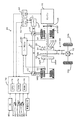
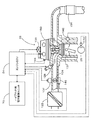
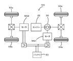
図1は、本発明の一実施例としての動力出力装置を搭載したハイブリッド自動車20の構成の概略を示す構成図であり、図2は、ハイブリッド自動車20に搭載されるエンジン22の構成の概略を示す構成図であり、図3は、ハイブリッド自動車20に搭載されるインバータ41の構成の概略を示す構成図である。実施例のハイブリッド自動車20は、図示するように、エンジン22と、エンジン22の出力軸としてのクランクシャフト26に
ダンパ28を介して接続された3軸式の動力分配統合機構30と、動力分配統合機構30に接続された発電可能なモータMG1と、動力分配統合機構30に接続された駆動軸としてのリングギヤ軸32aに取り付けられた減速ギヤ35と、この減速ギヤ35に接続されたモータMG2と、動力出力装置全体をコントロールするハイブリッド用電子制御ユニット70とを備える。
FIG. 1 is a configuration diagram showing an outline of a configuration of a
エンジン22は、例えばガソリンまたは軽油などの炭化水素系の燃料により動力を出力可能な内燃機関として構成されており、エアクリーナ122により清浄された空気をスロットルバルブ124を介して吸入する共に燃料噴射弁126からガソリンを噴射して吸入された空気とガソリンとを混合し、この混合気を吸気バルブ128を介して燃料室に吸入し、点火プラグ130による電気火花によって爆発燃焼させて、そのエネルギにより押し下げられるピストン132の往復運動をクランクシャフト26の回転運動に変換する。エンジン22からの排気は、一酸化炭素(CO)や炭化水素(HC),窒素酸化物(NOx)の有害成分を浄化する浄化装置(三元触媒)134を介して外気へ排出されるようになっている。
The
エンジン22は、エンジン用電子制御ユニット(以下、エンジンECUという)24により制御されている。エンジンECU24には、エンジン22の状態を検出する種々のセンサからの信号が図示しない入力ポートを介して入力されている。例えば、エンジンECU24には、クランクシャフト26の回転位置を検出するクランクポジションセンサ140からのクランクポジションや、エンジン22の冷却水の温度を検出する水温センサ142からの冷却水温、燃焼室へ吸排気を行なう吸気バルブ128や排気バルブを開閉するカムシャフトの回転位置を検出するカムポジションセンサ144からのカムポジション、スロットルバルブ124のポジションを検出するスロットルバルブポジションセンサ146からのスロットルポジションSPなどが入力ポートを介して入力されている。また、エンジンECU24からは、エンジン22を駆動するための種々の制御信号が図示しない出力ポートを介して出力されている。例えば、エンジンECU24からは、燃料噴射弁126への駆動信号や、スロットルバルブ124のポジションを調節するスロットルモータ136への駆動信号、イグナイタと一体化されたイグニッションコイル138への制御信号、吸気バルブ128の開閉タイミングの変更可能な可変バルブタイミング機構150への制御信号などが出力ポートを介して出力されている。なお、エンジンECU24は、ハイブリッド用電子制御ユニット50と通信しており、ハイブリッド用電子制御ユニット50からの制御信号によりエンジン22を運転制御すると共に必要に応じてエンジン22の運転状態に関するデータを出力する。
The
動力分配統合機構30は、外歯歯車のサンギヤ31と、このサンギヤ31と同心円上に配置された内歯歯車のリングギヤ32と、サンギヤ31に噛合すると共にリングギヤ32に噛合する複数のピニオンギヤ33と、複数のピニオンギヤ33を自転かつ公転自在に保持するキャリア34とを備え、サンギヤ31とリングギヤ32とキャリア34とを回転要素として差動作用を行なう遊星歯車機構として構成されている。動力分配統合機構30は、キャリア34にはエンジン22のクランクシャフト26が、サンギヤ31にはモータMG1が、リングギヤ32にはリングギヤ軸32aを介して減速ギヤ35がそれぞれ連結されており、モータMG1が発電機として機能するときにはキャリア34から入力されるエンジン22からの動力をサンギヤ31側とリングギヤ32側にそのギヤ比に応じて分配し、モータMG1が電動機として機能するときにはキャリア34から入力されるエンジン22からの動力とサンギヤ31から入力されるモータMG1からの動力を統合してリングギヤ32側に出力する。リングギヤ32に出力された動力は、リングギヤ軸32aからギヤ機構60およびデファレンシャルギヤ62を介して、最終的には車両の駆動輪63a,63bに出力される。
The power distribution and
モータMG1およびモータMG2は、いずれも発電機として駆動することができると共に電動機として駆動できる周知の同期発電電動機として構成されており、インバータ41,42を介してバッテリ50と電力のやりとりを行なう。モータMG1,MG2は、いずれもモータ用電子制御ユニット(以下、モータECUという)40により駆動制御されている。モータECU40には、モータMG1,MG2を駆動制御するために必要な信号、例えばモータMG1,MG2の回転子の回転位置を検出する回転位置検出センサ43,44からの信号や図示しない電流センサにより検出されるモータMG1,MG2に印加される相電流iu,ivなどが入力されており、モータECU40からは、インバータ41,42へのスイッチング制御信号が出力されている。モータECU40は、ハイブリッド用電子制御ユニット70と通信しており、ハイブリッド用電子制御ユニット70からの制御信号によってモータMG1,MG2を駆動制御すると共に必要に応じてモータMG1,MG2の運転状態に関するデータをハイブリッド用電子制御ユニット70に出力する。
The motor MG1 and the motor MG2 are both configured as well-known synchronous generator motors that can be driven as generators and can be driven as motors, and exchange power with the
インバータ41,42は、電力ライン54でバッテリ50とを接続されている。電力ライン54は、各インバータ41,42が共用する正極母線および負極母線として構成されており、モータMG1,MG2のいずれかで発電される電力を他のモータで消費することができるようになっている。インバータ41は、モータECU40からの制御信号を受けてスイッチングするトランジスタTr1,Tr2,Tr3,Tr4,Tr5,Tr6と、トランジスタTr1,Tr2,Tr3,Tr4,Tr5,Tr6に並列に接続されたダイオードD1,D2,D3,D4,D5,D6とを備える。インバータ41は、トランジスタTr1,Tr2,Tr3,Tr4,Tr5,Tr6のスイッチングにより、バッテリ50からの直流電流を三相交流電流に変換してモータMG1に供給しモータMG1を駆動したり、モータMG1からの三相交流電流を整流してバッテリ50やインバータ42へ供給したりする。
The
バッテリ50は、バッテリ用電子制御ユニット(以下、バッテリECUという)52によって管理されている。バッテリECU52には、バッテリ50を管理するのに必要な信号、例えば,バッテリ50の端子間に設置された図示しない電圧センサからの端子間電圧,バッテリ50の出力端子に接続された電力ライン54に取り付けられた図示しない電流センサからの充放電電流,バッテリ50に取り付けられた温度センサ51からの電池温度Tbなどが入力されており、必要に応じてバッテリ50の状態に関するデータを通信によりハイブリッド用電子制御ユニット70に出力する。なお、バッテリECU52では、バッテリ50を管理するために電流センサにより検出された充放電電流の積算値に基づいて残容量(SOC)も演算している。
The
ハイブリッド用電子制御ユニット70は、CPU72を中心とするマイクロプロセッサとして構成されており、CPU72の他に処理プログラムを記憶するROM74と、データを一時的に記憶するRAM76と、図示しない入出力ポートおよび通信ポートとを備える。ハイブリッド用電子制御ユニット70には、イグニッションスイッチ80からのイグニッション信号,操作者の操作に基づいてシフトをパーキング,前進走行,後進走行,ニュートラルに操作するシフトレバー81の操作位置を検出するシフトポジションセンサ82からのシフトポジションSP,アクセルペダル83の踏み込み量を検出するアクセルペダルポジションセンサ84からのアクセル開度Acc,ブレーキペダル85の踏み込み量を検出するブレーキペダルポジションセンサ86からのブレーキペダルポジションBP,車速センサ88からの車速Vなどが入力ポートを介して入力されている。ハイブリッド用電子制御ユニット70は、前述したように、エンジンECU24やモータECU40,バッテリECU52と通信ポートを介して接続されており、エンジンECU24やモータECU40,バッテリECU52と各種制御信号やデータのやりとりを行なっている。
The hybrid
こうして構成された実施例のハイブリッド自動車20は、運転者によるアクセルペダル83の踏み込み量に対応するアクセル開度Accと車速Vとに基づいて駆動軸としてのリングギヤ軸32aに出力すべき要求トルクを計算し、この要求トルクに対応する要求動力がリングギヤ軸32aに出力されるように、エンジン22とモータMG1とモータMG2とが運転制御される。エンジン22とモータMG1とモータMG2の運転制御としては、要求動力に見合う動力がエンジン22から出力されるようにエンジン22を運転制御すると共にエンジン22から出力される動力のすべてが動力分配統合機構30とモータMG1とモータMG2とによってトルク変換されてリングギヤ軸32aに出力されるようモータMG1およびモータMG2を駆動制御するトルク変換運転モードや要求動力とバッテリ50の充放電に必要な電力との和に見合う動力がエンジン22から出力されるようにエンジン22を運転制御すると共にバッテリ50の充放電を伴ってエンジン22から出力される動力の全部またはその一部が動力分配統合機構30とモータMG1とモータMG2とによるトルク変換を伴って要求動力がリングギヤ軸32aに出力されるようモータMG1およびモータMG2を駆動制御する充放電運転モード、エンジン22の運転を停止してモータMG2からの要求動力に見合う動力をリングギヤ軸32aに出力するよう運転制御するモータ運転モードなどがある。
The
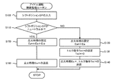
次に、こうして構成された実施例のハイブリッド自動車20の動作、特にエンジン22をアイドル運転する際の動作について説明する。図4は、ハイブリッド用電子制御ユニット70により実行されるアイドル運転制御ルーチンの一例を示すフローチャートである。このルーチンは、エンジン22がアイドル運転している際に所定時間毎(例えば8msec毎)に繰り返し実行される。
Next, the operation of the
アイドル運転制御ルーチンが実行されると、ハイブリッド用電子制御ユニット70のCPU72は、まず、シフトポジションセンサ81からのシフトポジションSPなど必要なデータを入力する処理を実行し(ステップS100)、シフトポジションSPが、ニュートラルであるか否かを判定する(ステップS110)。シフトポジションSPがニュートラルでなければ、通常のアイドル運転が可能であると判断して、エンジン22の点火時期Ea*をエンジン22が最も燃費が良くなる点火時期Eaに設定する(ステップS120)と共にモータMG1のトルク指令Tm1*を値0に設定する(ステップS130)。
When the idle operation control routine is executed, the
こうしてエンジン22の点火時期Ea*やモータMG1のトルク指令Tm1*を設定すると、エンジン22の点火時期Ea*についてはエンジンECU24に、モータMG1のトルク指令Tm1*についてはモータECU40にそれぞれ送信して(ステップS140)、本制御ルーチンを終了する。エンジン22の点火時期Ea*を受信したエンジンECU24は、エンジン22が設定された点火時期Ea*で点火するようクランクポジションセンサ140からのクランクポジション信号などに基づいてイグニッションコイル138への制御信号のタイミングを点火時期Ea*にする点火制御を行う。また、トルク指令Tm1*を受信したモータECU40は、トルク指令Tm1*でモータMG1が駆動されるようインバータ41のトランジスタTr1,Tr2,Tr3,Tr4,Tr5,Tr6のスイッチング制御を行なう。このようにシフトポジションSPがニュートラルではないときには、エンジン22を目標アイドル回転数で安定して運転することができると共にエンジン22の点火時期をエンジン22が効率よく動作できるような点火時期に設定するから燃費の向上を図ることができる。
When the ignition timing Ea * of the
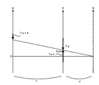
一方、ステップS110でシフトポジションSPがニュートラルであると判定されると、通常のアイドル運転のときよりエンジン22から出力されるトルクが大きくなるようエンジン22の点火時期Ea*を通常のアイドル運転での点火時期EaからEα進角(例えば、5°進角)させた時期に設定する(ステップS150)。ここで、エンジン22の点火時期を進角させる理由について説明する。実施例では、シフトポジションSPがニュー
トラルであるときには、駆動軸としてのリングギヤ軸32aに動力が出力されないようインバータ41への電力供給を遮断する。このため、トランジスタTr1,Tr2,Tr3,Tr4,Tr5,Tr6が遮断状態になりモータMG1を駆動制御することができない。シフトポジションSPがニュートラルであるときの動力分配統合機構30の回転要素における回転数とトルクとの力学的な関係を示す共線図を図5に示す。この場合にはモータMG1の駆動制御ができないから、エンジン22を目標アイドル回転数Nei*で運転させると、エンジン22によりモータMG1が連れ回される。このようにモータMG1が連れ回されるとモータMG1の逆起電力によりエンジン22の出力軸であるキャリア34に負のトルクTαが作用する。このような負のトルクTαがキャリア34に作用するとエンジン22の回転数が低下しエンジン22を目標アイドル回転数Nei*で安定して運転することができない。そこで、エンジン22の点火時期を通常のアイドル運転での点火時期より進角させ通常のアイドル運転のときよりエンジン22から出力されるトルクTe*を大きくすることにより、キャリア34に作用する負のトルクTαをキャンセルすることができる。
On the other hand, if it is determined in step S110 that the shift position SP is neutral, the ignition timing Ea * of the
こうして点火時期Ea*が設定されると、設定された点火時期Ea*をエンジンECU24に送信して(ステップS160)、本制御ルーチンを終了する。このように、シフトポジションSPがニュートラルであるときには、エンジン22の点火時期を進角させエンジン22から出力されるトルクを大きくすることにより、エンジン22で連れ回れるモータMG1の逆起電力によりエンジン22の出力軸であるキャリア34に作用する負のトルクTαをキャンセルすることができる。この結果、エンジン22を目標アイドル回転数Nei*で安定して運転することができる。
When the ignition timing Ea * is set in this way, the set ignition timing Ea * is transmitted to the engine ECU 24 (step S160), and this control routine is ended. Thus, when the shift position SP is neutral, the ignition timing of the
以上説明した実施例のハイブリッド自動車20によれば、エンジン22をアイドル運転している際にシフトポジションSPがニュートラルであるときには、エンジン22の点火時期を進角させエンジン22から出力されるトルクを大きくすることによりエンジン22の出力軸であるキャリア34に作用する負のトルクTαをキャンセルする。この結果、エンジン22を目標アイドル回転数で安定して運転することができる。また、シフトポジションSPがニュートラル以外であるときには、エンジン22を目標アイドル回転数で安定して運転することができると共にエンジン22の点火時期をエンジン22の燃費が最もよくなる点火時期に設定できるので燃費の向上を図ることができる。
According to the
実施例のハイブリッド自動車20では、シフトポジションSPがニュートラルのときには、エンジン22の点火時期を通常のアイドル運転のときより進角側に設定するものとしたが、エンジン22から出力されるトルクが通常のアイドル運転のときより大きくなればどのような制御量を用いてもよく、例えば、通常のアイドル運転のときよりスロットルバルブ120の開度を大きくしてエンジン22の吸入空気量を増加させるものとしてもよい。
In the
実施例のハイブリッド自動車20では、シフトポジションSPがニュートラルのときにエンジン22の点火時期を進角側に設定するものとしたが、インバータ41のトランジスタTr1,Tr2,Tr4,Tr5,Tr6が遮断状態であるときにエンジン22の点火時期を進角側に設定してもよいので、シフトポジションSPがニュートラル以外であるときでもインバータ41のトランジスタTr1,Tr2,Tr4,Tr5,Tr6が遮断状態であればエンジン22の点火時期を進角側に設定してもよい。
In the
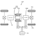
実施例のハイブリッド自動車20では、モータMG2の動力を減速ギヤ35により変速してリングギヤ軸32aに出力するものとしたが、図6の変形例のハイブリッド自動車120に例示するように、モータMG2の動力をリングギヤ軸32aが接続された車軸(駆動輪63a,63bが接続された車軸)とは異なる車軸(図6における車輪64a,64
bに接続された車軸)に接続するものとしてもよい。
In the
It is good also as what connects to the axle connected to b.
実施例のハイブリッド自動車20では、エンジン22の動力を動力分配統合機構30を介して駆動輪63a,63bに接続された駆動軸としてのリングギヤ軸32aに出力するものとしたが、図7の変形例のハイブリッド自動車220に例示するように、エンジン22のクランクシャフト26に接続されたインナーロータ232と駆動輪63a,63bに動力を出力する駆動軸に接続されたアウターロータ234とを有し、エンジン22の動力の一部を駆動軸に伝達すると共に残余の動力を電力に変換する対ロータ電動機230を備えるものとしてもよい。
In the
以上、本発明を実施するための最良の形態について実施例を用いて説明したが、本発明はこうした実施例に何等限定されるものではなく、本発明の要旨を逸脱しない範囲内において、種々なる形態で実施し得ることは勿論である。 The best mode for carrying out the present invention has been described with reference to the embodiments. However, the present invention is not limited to these embodiments, and various modifications can be made without departing from the gist of the present invention. Of course, it can be implemented in the form.
本発明は、自動車産業などに利用可能である。 The present invention is applicable to the automobile industry and the like.
20,120,220 ハイブリッド自動車、22 エンジン、24 エンジン用電子制御ユニット(エンジンECU)、26 クランクシャフト、28 ダンパ、30 動力分配統合機構、31 サンギヤ、32 リングギヤ、32a リングギヤ軸、33 ピニオンギヤ、34 キャリア、35,減速ギヤ、40 モータ用電子制御ユニット(モータECU)、41,42 インバータ、43,44 回転位置検出センサ、50 バッテリ、51 温度センサ、52 バッテリ用電子制御ユニット(バッテリECU)、54 電力ライン、60 ギヤ機構、62 デファレンシャルギヤ、63a,63b,64a,64b 駆動輪、70 ハイブリッド用電子制御ユニット、72 CPU、74 ROM、76 RAM、80 イグニッションスイッチ、81 シフトレバー、82 シフトポジションセンサ、83 アクセルペダル、84 アクセルペダルポジションセンサ、85 ブレーキペダル、86 ブレーキペダルポジションセンサ、88 車速センサ、230 対ロータ電動機、232 インナーロータ 234 アウターロータ、D1,D2,D3,D4,D5,D6 ダイオード、MG1,MG2 モータ、Tr1,Tr2,Tr3,Tr4,Tr5,Tr6 トランジスタ。
20, 120, 220 Hybrid vehicle, 22 engine, 24 engine electronic control unit (engine ECU), 26 crankshaft, 28 damper, 30 power distribution integration mechanism, 31 sun gear, 32 ring gear, 32a ring gear shaft, 33 pinion gear, 34 carrier , 35, reduction gear, 40 motor electronic control unit (motor ECU), 41, 42 inverter, 43, 44 rotational position detection sensor, 50 battery, 51 temperature sensor, 52 battery electronic control unit (battery ECU), 54 electric power Line, 60 gear mechanism, 62 differential gear, 63a, 63b, 64a, 64b driving wheel, 70 hybrid electronic control unit, 72 CPU, 74 ROM, 76 RAM, 80 ignition switch, 8 1 shift lever, 82 shift position sensor, 83 accelerator pedal, 84 accelerator pedal position sensor, 85 brake pedal, 86 brake pedal position sensor, 88 vehicle speed sensor, 230 rotor motor, 232
Claims (9)
内燃機関と、
該内燃機関の出力軸と前記駆動軸とに接続され、回転磁界による電力の入出力を伴って該内燃機関からの動力の少なくとも一部を該駆動軸に出力可能な電力動力入出力手段と、
充放電可能な蓄電手段と、
該蓄電手段と前記電力動力入出力手段とに接続され、スイッチング素子のスイッチングにより該電力動力入出力手段を駆動する駆動回路と、
該駆動回路のスイッチング素子によるスイッチングを伴って前記内燃機関をアイドル回転数で運転するときには第1の制御量により該内燃機関を運転制御し、前記駆動回路のスイッチング素子によるスイッチングの禁止を伴って前記内燃機関をアイドル回転数で運転するときには前記第1の制御量とは異なる第2の制御量により該内燃機関を運転制御するアイドル運転制御手段と、
を備える動力出力装置。 A power output device that outputs power to a drive shaft,
An internal combustion engine;
Power power input / output means connected to the output shaft of the internal combustion engine and the drive shaft, and capable of outputting at least part of the power from the internal combustion engine to the drive shaft with input / output of power by a rotating magnetic field;
Charge / discharge power storage means;
A drive circuit connected to the power storage means and the power power input / output means and driving the power power input / output means by switching of a switching element;
When the internal combustion engine is operated at an idling speed with switching by the switching element of the drive circuit, the internal combustion engine is controlled by a first control amount, and switching is prohibited by the switching element of the drive circuit. Idle operation control means for controlling the operation of the internal combustion engine by a second control amount different from the first control amount when the internal combustion engine is operated at an idle speed;
A power output device comprising:
前記内燃機関の点火時期を調節する点火時期調節手段を備え、
前記アイドル運転制御手段は、前記駆動回路のスイッチング素子によるスイッチングを伴って前記内燃機関をアイドル回転数で運転するときには通常の点火時期で該内燃機関が点火するよう前記点火時期調節手段を制御し、前記駆動回路のスイッチング素子によるスイッチングの禁止を伴って前記内燃機関をアイドル回転数で運転するときには前記通常の点火時期より進角側で該内燃機関が点火されるよう前記点火時期調節手段を制御する手段である
動力出力装置。 The power output device according to claim 2,
Ignition timing adjusting means for adjusting the ignition timing of the internal combustion engine,
The idle operation control means controls the ignition timing adjusting means so that the internal combustion engine is ignited at a normal ignition timing when the internal combustion engine is operated at an idle rotation speed with switching by a switching element of the drive circuit, The ignition timing adjusting means is controlled so that the internal combustion engine is ignited at a more advanced angle than the normal ignition timing when the internal combustion engine is operated at an idle speed with the prohibition of switching by the switching element of the drive circuit. Power output device that is means.
前記内燃機関の吸入空気量を調節する吸入空気量調節手段を備え、
前記アイドル運転制御手段は、前記駆動回路のスイッチング素子によるスイッチングを伴って前記内燃機関をアイドル回転数で運転するときには通常の吸入空気量で該内燃機関が運転されるよう前記吸入空気量調節手段を制御し、前記駆動回路のスイッチング素子によるスイッチングの禁止を伴って前記内燃機関をアイドル回転数で運転するときには前記通常の吸入空気量より多い空気量で該内燃機関が運転されるよう前記吸入空気量調節手段を制御する手段である
動力出力装置。 The power output device according to claim 2 or 3,
An intake air amount adjusting means for adjusting the intake air amount of the internal combustion engine;
The idle operation control means includes the intake air amount adjusting means so that the internal combustion engine is operated with a normal intake air amount when the internal combustion engine is operated at an idle speed with switching by a switching element of the drive circuit. The intake air amount so that the internal combustion engine is operated with an air amount greater than the normal intake air amount when the internal combustion engine is operated at idle speed with the switching prohibited by the switching element of the drive circuit. A power output device which is means for controlling the adjusting means.
操作者の操作に基づいてパーキング,前進走行,後進走行,ニュートラルを含むシフト操作が可能なシフト手段を備え、
前記制御手段は、前記シフト手段が前記ニュートラルに操作されている最中に前記内燃機関をアイドル運転する際に前記駆動回路のスイッチング素子によるスイッチングの禁止を伴って前記内燃機関をアイドル回転数で運転する手段である
自動車。 The automobile according to claim 7,
Shift means capable of shifting operations including parking, forward traveling, reverse traveling, and neutral based on the operation of the operator,
The control means operates the internal combustion engine at an idle speed with a prohibition of switching by a switching element of the drive circuit when the internal combustion engine is idling while the shift means is being operated neutrally. A vehicle that is a means to do.
前記駆動回路のスイッチング素子によるスイッチングを伴って前記内燃機関をアイドル回転数で運転するときには第1の制御量により該内燃機関を運転制御し、前記駆動回路のスイッチング素子によるスイッチングの禁止を伴って前記内燃機関をアイドル回転数で運転するときには前記第1の制御量とは異なる第2の制御量により該内燃機関を運転制御する
動力出力装置の制御方法。 An electric power input / output connected to the internal combustion engine, and an output shaft and a drive shaft of the internal combustion engine, and capable of outputting at least part of the power from the internal combustion engine to the drive shaft with input / output of electric power by a rotating magnetic field Means, chargeable / dischargeable power storage means, and a drive circuit connected to the power storage means and the power motive power input / output means for driving the power motive power input / output means by switching of a switching element. A method for controlling a power output device that outputs power,
When the internal combustion engine is operated at an idle speed with switching by the switching element of the drive circuit, the internal combustion engine is controlled by a first control amount, and the switching is prohibited by the switching element of the drive circuit. A control method for a power output apparatus, wherein when the internal combustion engine is operated at an idle speed, the internal combustion engine is controlled to operate by a second control amount different from the first control amount.
Priority Applications (1)
| Application Number | Priority Date | Filing Date | Title |
|---|---|---|---|
| JP2004119355A JP2005299567A (en) | 2004-04-14 | 2004-04-14 | POWER OUTPUT DEVICE, ITS CONTROL METHOD, AND AUTOMOBILE |
Applications Claiming Priority (1)
| Application Number | Priority Date | Filing Date | Title |
|---|---|---|---|
| JP2004119355A JP2005299567A (en) | 2004-04-14 | 2004-04-14 | POWER OUTPUT DEVICE, ITS CONTROL METHOD, AND AUTOMOBILE |
Publications (1)
| Publication Number | Publication Date |
|---|---|
| JP2005299567A true JP2005299567A (en) | 2005-10-27 |
Family
ID=35331410
Family Applications (1)
| Application Number | Title | Priority Date | Filing Date |
|---|---|---|---|
| JP2004119355A Pending JP2005299567A (en) | 2004-04-14 | 2004-04-14 | POWER OUTPUT DEVICE, ITS CONTROL METHOD, AND AUTOMOBILE |
Country Status (1)
| Country | Link |
|---|---|
| JP (1) | JP2005299567A (en) |
Cited By (2)
| Publication number | Priority date | Publication date | Assignee | Title |
|---|---|---|---|---|
| US7762232B2 (en) * | 2008-11-06 | 2010-07-27 | Ford Global Technologies, Llc | Engine and exhaust heating for hybrid vehicle |
| US8118008B2 (en) | 2008-11-06 | 2012-02-21 | Ford Global Technologies, Llc | Engine and exhaust heating |
-
2004
- 2004-04-14 JP JP2004119355A patent/JP2005299567A/en active Pending
Cited By (5)
| Publication number | Priority date | Publication date | Assignee | Title |
|---|---|---|---|---|
| US7762232B2 (en) * | 2008-11-06 | 2010-07-27 | Ford Global Technologies, Llc | Engine and exhaust heating for hybrid vehicle |
| US7997252B2 (en) | 2008-11-06 | 2011-08-16 | Ford Global Technologies, Llc | Engine and exhaust heating for hybrid vehicle |
| US8118008B2 (en) | 2008-11-06 | 2012-02-21 | Ford Global Technologies, Llc | Engine and exhaust heating |
| US8181629B2 (en) | 2008-11-06 | 2012-05-22 | Ford Global Technologies, Llc | Engine and exhaust heating for hybrid vehicle |
| US8245691B2 (en) | 2008-11-06 | 2012-08-21 | Ford Global Technologies, Llc | Engine and exhaust heating |
Similar Documents
| Publication | Publication Date | Title |
|---|---|---|
| JP4474293B2 (en) | Hybrid vehicle and control method thereof | |
| JP4123254B2 (en) | Internal combustion engine misfire determination device and internal combustion engine misfire determination method | |
| JP4258557B2 (en) | Internal combustion engine device and control method for internal combustion engine device | |
| CN101646587B (en) | Vehicle and control method thereof | |
| JP4850801B2 (en) | INTERNAL COMBUSTION ENGINE DEVICE, VEHICLE MOUNTING THE SAME, AND METHOD FOR CONTROLLING INTERNAL COMBUSTION ENGINE DEVICE | |
| JP4293266B2 (en) | Hybrid car | |
| JP4321520B2 (en) | POWER OUTPUT DEVICE, VEHICLE MOUNTING THE SAME, AND METHOD FOR CONTROLLING POWER OUTPUT DEVICE | |
| JP4259403B2 (en) | POWER OUTPUT DEVICE, HYBRID VEHICLE HAVING THE SAME, AND METHOD FOR CONTROLLING POWER OUTPUT DEVICE | |
| JP4222427B2 (en) | Vehicle and control method thereof | |
| JP4254762B2 (en) | Power output apparatus, automobile equipped with the same, and control method of power output apparatus | |
| JPH10288028A (en) | Operation control device for hybrid vehicle | |
| JP4086010B2 (en) | Power output apparatus, automobile equipped with the same, and control method of power output apparatus | |
| JP2005320911A (en) | Power output device, automobile having the power output device, and method of controlling the power output device | |
| JP2004360672A (en) | Power output device, control method therefor, and vehicle equipped with the same | |
| JP2010083319A (en) | Hybrid vehicle and method for controlling the same | |
| JP2007302185A (en) | POWER OUTPUT DEVICE, ITS CONTROL METHOD, AND VEHICLE | |
| JP2004251178A (en) | Vehicle control device | |
| JP4196960B2 (en) | Power output apparatus, automobile equipped with the same, and control method therefor | |
| JP5246090B2 (en) | Hybrid vehicle and control method thereof | |
| JP4285552B2 (en) | Vehicle and control method thereof | |
| JP2005273490A (en) | STARTING DEVICE AND STARTING METHOD FOR INTERNAL COMBUSTION ENGINE | |
| JP2013067297A (en) | Hybrid vehicle | |
| JP2005299567A (en) | POWER OUTPUT DEVICE, ITS CONTROL METHOD, AND AUTOMOBILE | |
| JP2006347430A (en) | Hybrid vehicle and control method thereof | |
| JP2010024891A (en) | Automobile and its control method |